![Acid Promoted Radical-Chain Difunctionalization of …4 Optimization of reaction conditions[a] Entry Oxidant Equiv. Acid Equiv. Additive T/ C Yield (%)[b] 1 BPO (1.5 equiv.) HCl (aq.,](https://static.fdocuments.in/doc/165x107/5f1cbe1099fd92028a750a29/acid-promoted-radical-chain-difunctionalization-of-4-optimization-of-reaction-conditionsa.jpg)
Ball Equiv Load
2
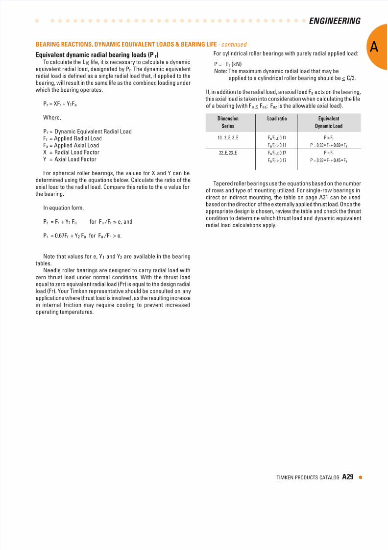
EnginEEring A TIMKEN PRODUCTS CATALOG A BEARING REACTIONS, DyNAMIC EQUIVALENT LOADS & BEARING LIFE - continued Equivalent dnamic radial bearing loads (P r ) T o calculate the L10 lie, it is necessary to calculate a dynamic equivalent radial load, designated by Pr . The dynamic equivalent radial load is defned as a single radial load that, i applied to the bearing, will result in the same lie as the combined loading under which the bearing operates. Pr = XFr + Y1Fa Where, Pr = Dynamic Equivalent Radial Load Fr = Applied Radial Load Fa = Applied Axial Load X = Radial Load Factor Y = Axial Load Factor For spherical roller bearings, the values or X and Y can be determined using the equations below. Calculate the ratio o the axial load to the radial load. Compare this ratio to the e value or the bearing. In equation orm, Pr = Fr + Y2 Fa or Fa / Fr e, and Pr = 0.67Fr + Y2 Fa or Fa / Fr > e. Note that values or e, Y 1 and Y2 are available in the bearing tables. Needle roller bearings are designed to carry radial load with zero thrust load under normal conditions. With the thrust load equal to zero equivale nt radial load (Pr) is equal to the design radial load (Fr). Your Timken representative should be consulted on any applications where thrust load is involved , as the resulting increase in internal riction may require cooling to prevent increased operating temperatures. T apered roller bearings use the equations based on the number o rows and type o mounting utilized. For single-row bearings in direct or indirect mounting, the table on page A31 can be used based on the direction o the e xternally applied thrust load. Once the appropriate design is chosen, review the table and check the thrust condition to determine which thrust load and dynamic equivalent radial load calculations apply. For cylindrical roller bearings with purely radial applied load: P = Fr (kN) Note: The maximum dynamic radial load that may be applied to a cylindrical roller bearing should be < C/3. I, in addition to the radial load, an axial load Fa acts on the bearing, this axial load is taken into consideration when calculating the lie o a bearing (with Fa < Faz; Faz is the allowable axial load). Dimension Load ratio Equivalent Series Dynamic Load 10.. 2..E, 3..E Fa /Fr < 0.11 P = Fr Fa /Fr > 0.11 P = 0.93 • Fr + 0.69 • Fa 22..E, 23..E Fa /Fr < 0.17 P = Fr Fa /Fr > 0.17 P = 0.93 • Fr + 0.45 • Fa
Transcript of Ball Equiv Load
8/6/2019 Ball Equiv Load
http://slidepdf.com/reader/full/ball-equiv-load 1/2
EnginEEring
TIMKEN PRODUCTS CATALOG A
BEARING REACTIONS, DyNAMIC EQUIVALENT LOADS & BEARING LIFE - continued
Equivalent dnamic radial bearing loads (Pr)To calculate the L10 lie, it is necessary to calculate a dynamic
equivalent radial load, designated by Pr. The dynamic equivalentradial load is defned as a single radial load that, i applied to thebearing, will result in the same lie as the combined loading underwhich the bearing operates.
Pr = XFr + Y1Fa
Where,
Pr = Dynamic Equivalent Radial LoadFr = Applied Radial LoadFa = Applied Axial LoadX = Radial Load FactorY = Axial Load Factor
For spherical roller bearings, the values or X and Y can bedetermined using the equations below. Calculate the ratio o theaxial load to the radial load. Compare this ratio to the e value or
the bearing.
In equation orm,
Pr = Fr + Y2 Fa or Fa / Fr e, and
Pr = 0.67Fr + Y2 Fa or Fa / Fr > e.
Note that values or e, Y1 and Y2 are available in the bearing tables.
Needle roller bearings are designed to carry radial load withzero thrust load under normal conditions. With the thrust loadequal to zero equivalent radial load (Pr) is equal to the design radial
load (Fr). Your Timken representative should be consulted on anyapplications where thrust load is involved, as the resulting increasein internal riction may require cooling to prevent increasedoperating temperatures.
Tapered roller bearings use the equations based on the numbe
o rows and type o mounting utilized. For single-row bearings indirect or indirect mounting, the table on page A31 can be usedbased on the direction o the externally applied thrust load. Once theappropriate design is chosen, review the table and check the thruscondition to determine which thrust load and dynamic equivalenradial load calculations apply.
For cylindrical roller bearings with purely radial applied load:
P = Fr (kN)Note: The maximum dynamic radial load that may be
applied to a cylindrical roller bearing should be < C/3.
I, in addition to the radial load, an axial load Fa acts on the bearing
this axial load is taken into consideration when calculating the lieo a bearing (with Fa < Faz; Faz is the allowable axial load).
Dimension Load ratio Equivalent
Series Dynamic Load
10.. 2..E, 3..E Fa /Fr < 0.11 P = Fr
Fa /Fr > 0.11 P = 0.93 • Fr + 0.69 • Fa
22..E, 23..E Fa /Fr < 0.17 P = Fr
Fa /Fr > 0.17 P = 0.93 • Fr + 0.45 • Fa
8/6/2019 Ball Equiv Load
http://slidepdf.com/reader/full/ball-equiv-load 2/2
EnginEEring
A
•A0 TIMKEN PRODUCTS CATALOG
BEARING REACTIONS, DyNAMIC EQUIVALENT LOADS & BEARING LIFE - continued
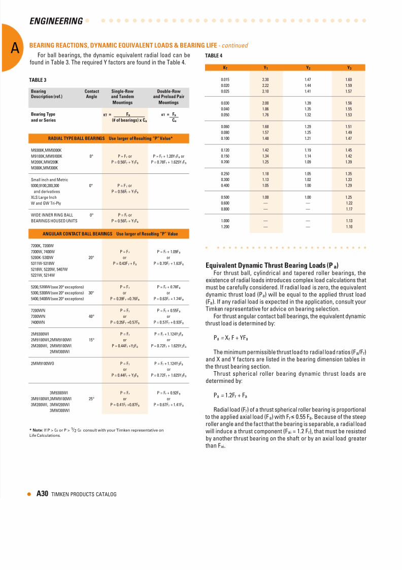
For ball bearings, the dynamic equivalent radial load can beound in Table 3. The required Y actors are ound in the Table 4.
Bearing Contact Single-Row Double-RowDescription (ref.) Angle and Tandem and Preload Pair
Mountings Mountings
Bearing Tpe KT = Fa KT = Fa
and or Series (# of bearings) x Co Co
RADIAL TyPE BALL BEARINGS Use larger of Resulting “P” Value*
M9300K,MM9300K
M9100K,MM9100K 0° P = Fr or P = Fr + 1.20Y1Fa or
M200K,MM200K P = 0.56Fr + Y1Fa P = 0.78Fr + 1.625Y1Fa
M300K,MM300K
Small inch and Metric
9300,9100,200,300 0° P = Fr or
and derivatives P = 0.56Fr + Y1Fa
XLS Large Inch
W and GW Tri-Ply
WIDE INNER RING BALL 0° P = Fr or
BEARINGS HOUSED UNITS P = 0.56Fr + Y1Fa
ANGULAR CONTACT BALL BEARINGS Use larger of Resulting “P” Value
7200K, 7200W
7300W, 7400W P = Fr P = Fr + 1.09Fa
5200K-5300W 20° or or
5311W-5318W P = 0.43Fr + Fa P = 0.70Fr + 1.63Fa
5218W, 5220W, 5407W
5221W, 5214W
5200, 5200W (see 20° exceptions) P = Fr P = Fr + 0.78Fa
5300, 5300W (see 20° exceptions) 30° or or
5400, 5400W (see 20° exceptions) P = 0.39Fr +0.76Fa P = 0.63Fr + 1.24Fa
7200WN P = Fr P = Fr + 0.55Fa
7300WN 40° or or
7400WN P = 0.35Fr +0.57Fa P = 0.57Fr + 0.93Fa
2M9300WI P = Fr P = Fr + 1.124Y2Fa
2M9100WI,2MM9100WI 15° or or
2M200WI, 2MM9100WI P = 0.44Fr +Y2Fa P = 0.72Fr + 1.625Y2Fa
2MM300WI
2MM9100WO P = Fr P = Fr + 1.124Y3Fa
or or
P = 0.44Fr + Y3Fa P = 0.72Fr + 1.625Y3Fa
3M9300WI P = Fr P = Fr + 0.92Fa
3M9100WI,3MM9100WI 25° or or3M200WI, 3MM200WI P = 0.41Fr +0.87Fa P = 0.67Fr + 1.41Fa
3MM300WI
TABLE
KT y y y
0.015 2.30 1.47 1.60
0.020 2.22 1.44 1.59
0.025 2.10 1.41 1.57
0.030 2.00 1.39 1.56
0.040 1.86 1.35 1.55
0.050 1.76 1.32 1.53
0.060 1.68 1.29 1.51
0.080 1.57 1.25 1.49
0.100 1.48 1.21 1.47
0.120 1.42 1.19 1.45
0.150 1.34 1.14 1.42
0.200 1.25 1.09 1.39
0.250 1.18 1.05 1.35
0.300 1.13 1.02 1.33
0.400 1.05 1.00 1.29
0.500 1.00 1.00 1.25
0.600 — — 1.22
0.800 — — 1.17
1.000 — — 1.13
1.200 — — 1.10
Equivalent Dnamic Thrust Bearing Loads (Pa)For thrust ball, cylindrical and tapered roller bearings, the
existence o radial loads introduces complex load calculations thatmust be careully considered. I radial load is zero, the equivalentdynamic thrust load (Pa) will be equal to the applied thrust load
(Fa). I any radial load is expected in the application, consult yourTimken representative or advice on bearing selection.
For thrust angular contact ball bearings, the equivalent dynamic thrust load is determined by:
Pa = Xr F + YFa
The minimum permissible thrust load to radial load ratios (Fa /Fr)and X and Y actors are listed in the bearing dimension tables in
the thrust bearing section.Thrust spherical roller bearing dynamic thrust loads are
determined by:
Pa = 1.2Fr + Fa
Radial load (Fr) o a thrust spherical roller bearing is proportional to the applied axial load (Fa) with Fr 0.55 Fa. Because o the steeproller angle and the act that the bearing is separable, a radial loadwill induce a thrust component (Fai = 1.2 Fr), that must be resistedby another thrust bearing on the shat or by an axial load greater
than Fai.
TABLE
*Note:If P > C0 or P > 1 / 2 CE consult with your Timken representative on
Life Calculations.