Ball-Bearing Products - Punch Tools
16
– Ball-Bearing Products www.anchorlamina.com Check our website for the latest technical information.
Transcript of Ball-Bearing Products - Punch Tools

– Ball-Bearing Products
www.anchorlamina.comCheck our website for the latest technical information.
2
Contents
Ball-Bearing Component Maintenance ................................................ 2Ball-Bearing Operating Data & Design Selection ................................ 3Ball-Bearing Retainers ........................................................................ 4Ball-Bearing Sleeve Bushings – Pressed Fit ....................................... 5Ball-Bearing Bushings – Tap Fit .......................................................... 6Ball-Bearing Guide Posts – Pressed Fit .............................................. 7Ball-Bearing Guide Posts – Tap Fit ...................................................... 8Ball-Bearing Retainers – Metric ........................................................... 9Ball-Bearing Bushings – Sleeve– Metric ........................................... 10Ball-Bearing Bushings – Tap Fit – Metric ............................................11Ball-Bearing Guide Posts – Straight – Metric .................................... 12Ball-Bearing Guide Posts – Tap Fit – Metric ...................................... 13Ball-Bearing Clamps & Screws ......................................................... 14Ball-Bearing Boring Procedures & Dimensions for Precision Dies .... 15Ball-Bearing Component Installation Instructions .............................. 16
Ball-Bearing Components
BALL-LUBE® & BALL-SCRUBB®
PARTNUMBER DESCRIPTION PART
NUMBER DESCRIPTION
ARS016 1 Pint BALL-SCRUBB® Spray ARL016 1 Pint BALL-LUBE® sprayARS384 1 Case (24) 1 Pint BALL-SCRUBB® ARL384 1 Case (24) 1 Pint BALL-LUBE®
ARS128 1 Gallon BALL-SCRUBB® ARL128 1 Gallon BALL-LUBE®
ARS640 5 Gallons BALL-SCRUBB® ARL640 5 Gallons BALL-LUBE®
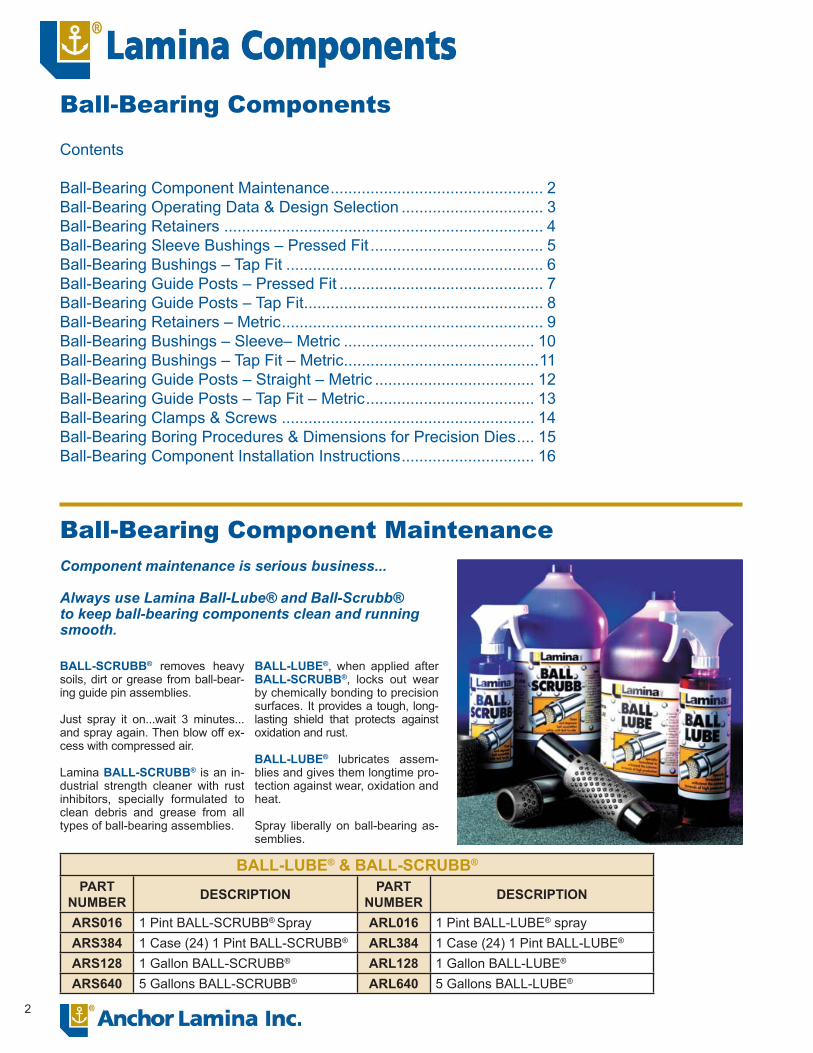
Ball-Bearing Component MaintenanceComponent maintenance is serious business...
Always use Lamina Ball-Lube® and Ball-Scrubb® to keep ball-bearing components clean and running smooth.
BALL-SCRUBB® removes heavy soils, dirt or grease from ball-bear-ing guide pin assemblies.
Just spray it on...wait 3 minutes... and spray again. Then blow off ex-cess with compressed air.
Lamina BALL-SCRUBB® is an in-dustrial strength cleaner with rust inhibitors, specially formulated to clean debris and grease from all types of ball-bearing assemblies.
BALL-LUBE®, when applied after BALL-SCRUBB®, locks out wear by chemically bonding to precision surfaces. It provides a tough, long-lasting shield that protects against oxidation and rust.
BALL-LUBE® lubricates assem-blies and gives them longtime pro-tection against wear, oxidation and heat.
Spray liberally on ball-bearing as-semblies.
3
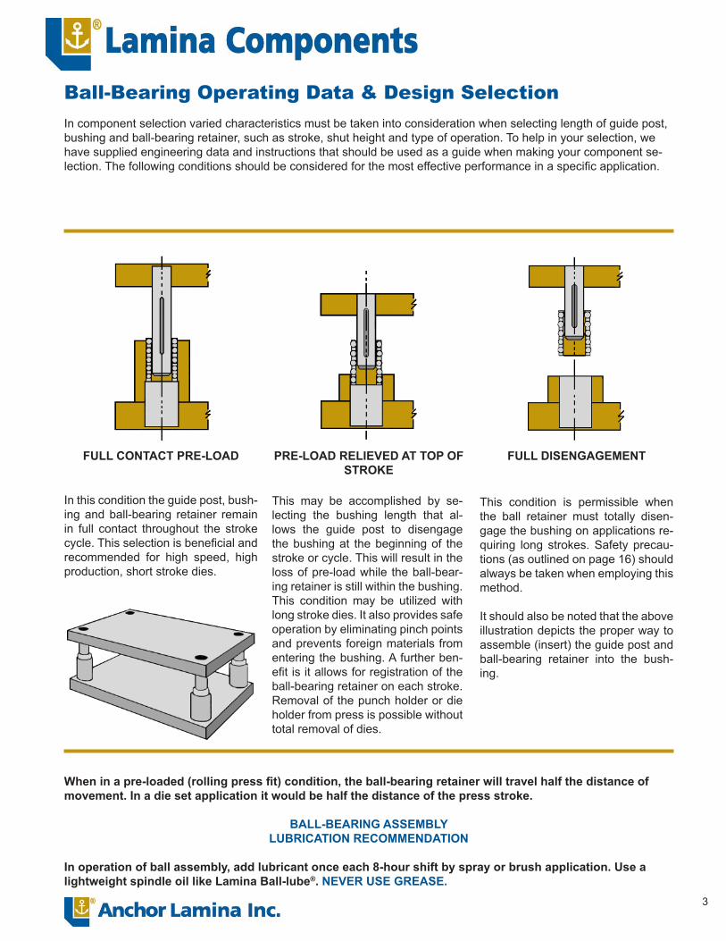
Ball-Bearing Operating Data & Design SelectionIn component selection varied characteristics must be taken into consideration when selecting length of guide post, bushing and ball-bearing retainer, such as stroke, shut height and type of operation. To help in your selection, we have supplied engineering data and instructions that should be used as a guide when making your component se-lection. The following conditions should be considered for the most effective performance in a specifi c application.
FULL CONTACT PRE-LOAD PRE-LOAD RELIEVED AT TOP OF STROKE
FULL DISENGAGEMENT
In this condition the guide post, bush-ing and ball-bearing retainer remain in full contact throughout the stroke cycle. This selection is benefi cial and recommended for high speed, high production, short stroke dies.
This may be accomplished by se-lecting the bushing length that al-lows the guide post to disengage the bushing at the beginning of the stroke or cycle. This will result in the loss of pre-load while the ball-bear-ing retainer is still within the bushing. This condition may be utilized with long stroke dies. It also provides safe operation by eliminating pinch points and prevents foreign materials from entering the bushing. A further ben-efi t is it allows for registration of the ball-bearing retainer on each stroke. Removal of the punch holder or die holder from press is possible without total removal of dies.
This condition is permissible when the ball retainer must totally disen-gage the bushing on applications re-quiring long strokes. Safety precau-tions (as outlined on page 16) should always be taken when employing this method.
It should also be noted that the above illustration depicts the proper way to assemble (insert) the guide post and ball-bearing retainer into the bush-ing.
When in a pre-loaded (rolling press fi t) condition, the ball-bearing retainer will travel half the distance of movement. In a die set application it would be half the distance of the press stroke.
BALL-BEARING ASSEMBLYLUBRICATION RECOMMENDATION
In operation of ball assembly, add lubricant once each 8-hour shift by spray or brush application. Use a lightweight spindle oil like Lamina Ball-lube®. NEVER USE GREASE.

4
Lamina ball-bearing retainers (AR1) are made of a heat-treated aluminum alloy that combines lightness and strength.
Each retainer is quality inspected for dimensional tolerance and all burrs are removed prior to ball insertion.
Ball bearings are of the highest qual-ity AAA1 Grade (25 millionth class), continually inspected to meet our ex-acting tolerance.
After the ball bearings have been inserted into the retainer, they are then staked using Lamina’s unique method that allows free movement with maximum security.
After staking, the retainers are then scrubbed to remove all metal par-
ticles that could cause accelerated tracking and grooving in the post and bushing.
Ball bearings are placed in retainers in an off-line radial pattern that offers optimum life in high or low speed presses.
Ball-bearing retainers are fastened to the guide post by means of a set screw and slot in guide post and are interchangeable with other manufac-turers using this method.
BALL-BEARING RETAINER(STANDARD)
PARTNUMBER D1 L1
AR1-0606
3/4”
1.50AR1-0607 1.75AR1-0608 2.00AR1-0609 2.25AR1-0610 2.50AR1-0806
1”
1.50AR1-0807 1.75AR1-0808 2.00AR1-0809 2.25AR1-0810 2.50AR1-1008
1-1/4”
2.00AR1-1009 2.25AR1-1010 2.50AR1-1011 2.75AR1-1012 3.00AR1-1013 3.25AR1-1210
1-1/2”
2.50A41-1211 2.75AR1-1212 3.00AR1-1213 3.25AR1-1214 3.50AR1-1215 3.75AR1-1411
1-3/4”
2.75AR1-1412 3.00AR1-1413 3.25AR1-1414 3.50AR1-1415 3.75AR1-1416 4.00AR1-1417 4.25AR1-1613
2”
3.25AR1-1614 3.50AR1-1615 3.75AR1-1616 4.00AR1-1617 4.25AR1-1618 4.50AR1-1622 5.50AR1-2018
2-1/2”
4.50AR1-2020 5.00AR1-2022 5.50AR1-2024 6.00AR1-2025 6.25AR1-2026 6.50AR1-2028 7.00AR1-2420
3”5.00
AR1-2424 6.00AR1-2428 7.00
Part numbers highlighted in blue desig-nate that the retainer length is recom-mended for general die set applications. Lengths not highlighted are for limited space use and special applications.
Ball-Bearing – Retainers
Radial placement reduces wear and tracking

5
BALL-BEARING BUSHINGS – STRAIGHT SLEEVEPART
NUMBERNOM PIN DIA
D1 D2 L1 PARTNUMBER
NOMPINDIA
D1 D2 L1 PART NUMBER
NOM PIN DIA
D1 D2 L1
AB1-0607
3/4” 1.12691.1266
1.38721.3867
1.625 AB1-1214
1-1/2” 1.87661.8763
2.43722.4367
3.375 AB1-1619
2” 2.50162.5013
3.16223.1617
4.625AB1-0608 1.875 AB1-1215 3.625 AB1-1620 4.875AB1-0609 2.125 AB1-1216 3.875 AB1-1621 5.125AB1-0610 2.375 AB1-1217 4.125 AB1-1622 5.375AB1-0611 2.625 AB1-1218 4.375 AB1-1624 5.875AB1-0612 2.875 AB1-1219 4.625 AB1-1626 6.375AB1-0613 3.125 AB1-1220 4.875 AB1-1628 6.875AB1-0614 3.375 AB1-1221 5.125 AB1-1630 7.375AB1-0615 3.625 AB1-1222 5.375 AB1-1632 7.875AB1-0616 3.875 AB1-1224 5.875 AB1-1634 8.375AB1-0618 4.375 AB1-1226 6.375 AB1-1636 8.875AB1-0620 4.875 AB1-1228 6.875 AB1-1638 9.375AB1-0624 5.875 AB1-1230 7.375 AB1-1640 9.875AB1-0808
1” 1.37691.3766
1.71721.7167
1.875 AB1-1232 7.875 AB1-1642 10.375AB1-0809 2.125 AB1-1234 8.375 AB1-1644 10.875AB1-0810 2.375 AB1-1236 8.875 AB1-1648 11.875AB1-0811 2.625 AB1-1240 9.875 AB1-1652 12.875AB1-0812 2.875 AB1-1242 10.375 AB1-1656 13.875AB1-0813 3.125 AB1-1244 10.875 AB1-2022
2-1/2” 3.00163.0013
3.68223.6817
5.375AB1-0814 3.375 AB1-1248 11.875 AB1-2024 5.875AB1-0815 3.625 AB1-1412
1-3/4” 2.12662.1263
2.74722.7467
2.875 AB1-2026 6.375AB1-0816 3.875 AB1-1414 3.375 AB1-2028 6.875AB1-0817 4.125 AB1-1415 3.625 AB1-2030 7.375AB1-0818 4.375 AB1-1416 3.875 AB1-2032 7.875AB1-0819 4.625 AB1-1417 4.125 AB1-2034 8.375AB1-0820 4.875 AB1-1418 4.375 AB1-2036 8.875AB1-0822 5.375 AB1-1419 4.625 AB1-2038 9.375AB1-0824 5.875 AB1-1420 4.875 AB1-2040 9.875AB1-0826 6.375 AB1-1421 5.125 AB1-2042 10.375AB1-0828 6.875 AB1-1422 5.375 AB1-2044 10.875AB1-1010
1-1/4” 1.62661.6263
2.10722.1067
2.375 AB1-1424 5.875 AB1-2048 11.875AB1-1011 2.625 AB1-1426 6.375 AB1-2052 12.875AB1-1012 2.875 AB1-1428 6.875 AB1-2056 13.875AB1-1013 3.125 AB1-1430 7.375 AB1-2424
3” 3.50163.5013
4.18224.1817
5.875AB1-1014 3.375 AB1-1432 7.875 AB1-2426 6.375AB1-1015 3.625 AB1-1434 8.375 AB1-2428 6.875AB1-1016 3.875 AB1-1436 8.875 AB1-2430 7.375AB1-1017 4.125 AB1-1438 9.375 AB1-2432 7.875AB1-1018 4.375 AB1-1440 9.875 AB1-2434 8.375AB1-1019 4.625 AB1-1442 10.375 AB1-2436 8.875AB1-1020 4.875 AB1-1444 10.875 AB1-2438 9.375AB1-1022 5.375 AB1-1448 11.875 AB1-2440 9.875AB1-1024 5.875 AB1-1452 12.875 AB1-2442 10.375AB1-1026 6.375 AB1-1612
2” 2.50162.5013
3.16223.1617
2.875 AB1-2444 10.875AB1-1028 6.875 AB1-1614 3.375 AB1-2448 11.875AB1-1032 7.875 AB1-1615 3.625 AB1-2452 12.875AB1-1036 8.875 AB1-1616 3.875 AB1-2456 13.875AB1-1212 1-1/2” 1.8766
1.87632.43722.4367
2.875 AB1-1617 4.125 See page 15 for bore size information.AB1-1213 3.125 AB1-1618 4.375
Ball-Bearing Sleeve Bushings – Pressed Fit
Lamina’s Ball-Bearing Guide Assembly Bushings (AB1) are made from vacuum degassed chrome alloy steel, hardened to precise Rockwell limits to give minimum tracking, grooving and downtime.
Lamina’s ball-bearing bushings are ground and honed to exacting tolerance limits. Using electronic and air checking instruments on the I.D. and O.D. make them interchangeable and do not require select fi tting.
The top is chamferred on the I.D. to minimize wear and aid align-ment when disengagement is required.
To minimize bushing close-in which is a result of press fi t and to eliminate any additional grinding or honing, boring instructions are provided in this catalog.

6
BALL-BEARING BUSHINGS – DEMOUNTABLEPART
NUMBERNOMPINDIA
D1 D2 D3 D4 D5 L1 L3 L4
ABG0808ABG0809ABG0811ABG0812ABG0813ABG0814ABG0815
1” 1.37691.3766
1.71631.7160 1.920 1.995 1.775
1.8752.1252.6252.8753.1253.3753.625
1.000
0.8751.1251.6251.8752.1252.3752.625
ABG1010ABG1011ABG1012ABG1013ABG1014ABG1015ABG1016ABG1017ABG1018ABG1020ABG1022ABG1024
1-1/4” 1.62661.6263
2.10632.1060 2.280 2.355 2.125
2.3752.6252.8753.1253.3753.6253.8754.1254.3754.8755.3755.875
1.000
1.3751.6251.8752.1252.3752.6252.8753.1253.3753.8754.3754.875
ABG1212ABG1213ABG1214ABG1215ABG1216ABG1217ABG1218ABG1219ABG1220ABG1222ABG1224
1-1/2” 1.87661.8763
2.43632.4360 2.600 2.675 2.425
2.8753.1253.3753.6253.8754.1254.3754.6254.8755.3755.875
1.250
1.6251.8752.1252.3752.6252.8753.1253.3753.6254.1254.625
ABG1412ABG1414ABG1416ABG1417ABG1418ABG1419ABG1420ABG1421ABG1422ABG1424ABG1426ABG1428ABG1430
1-3/4” 2.12662.1263
2.74632.7460 2.920 2.995 2.755
2.8753.3753.8754.1254.3754.6254.8755.1255.3755.8756.3756.8757.375
1.250
1.6252.1252.6252.8753.1253.3753.6253.8754.1254.6255.1255.6256.125
ABG1612ABG1614ABG1615ABG1616ABG1617ABG1618ABG1619ABG1620ABG1621ABG1622ABG1624ABG1626ABG1628ABG1630
2” 2.50162.5013
3.16133.1610 3.500 3.565 3.295
2.8753.3753.6253.8754.1254.3754.6254.8755.1255.3755.8756.3756.8757.375
1.250
1.6252.1252.3752.6252.8753.1253.3753.6253.8754.1254.6255.1255.6256.125
ABG2020ABG2022ABG2024ABG2026ABG2028ABG2030
2-1/2” 3.00163.0013
3.68133.6810 4.000 4.075 3.765
4.8755.3755.8756.3756.8757.375
1.250
3.6254.1254.6255.1255.6256.125
ABG2420ABG2422ABG2424ABG2426ABG2428ABG2430
3” 3.50163.5013
4.18134.1810 4.500 4.575 4.275
4.8755.3755.8756.3756.8757.375
1.250
3.6254.1254.6255.1255.6256.125
Ball-Bearing – Bushings –Tap Fit
Demountable shoulder bushings offer all the advantages of straight sleeve bush-ings and combine them with the conve-nience of easy assembly and disassembly.
These clamp type bushings are meant to be wring fi t into the die shoe and should never be forced or inserted by hammer-ing.
X-40-Clamps and socket head screws are provided to hold the bushings in place.
Unground demountable bushings are available by special order only.
Clamping information is on page 14.See page 15 for bore size information.
D4D2
.187L4
L1
5/16-18 S.H.C.S.
L3
D3D5D1

7
BALL-BEARING GUIDE POSTS – STRAIGHTPART
NUMBERNOMPINDIA
D1 L1 L2 L3 PARTNUMBER
NOM PIN DIA D1 L1 L2 L3
AP1-0612
3/4” .7530.7527
2.875 0.625 0.813 AP1-1422
1-3/4” 1.75301.7525
5.375 1.313 1.313AP1-0613 3.125 0.625 0.813 AP1-1423 5.625 1.500 1.500AP1-0614 3.375 0.625 0.813 AP1-1424 5.875 1.500 1.500AP1-0615 3.625 0.625 0.813 AP1-1425 6.125 1.500 1.500AP1-0616 3.875 0.625 0.813 AP1-1426 6.375 1.625 1.750AP1-0617 4.125 0.625 0.813 AP1-1428 6.875 1.625 1.750AP1-0618 4.375 0.625 0.813 AP1-1430 7.375 1.625 1.750AP1-0619 4.625 0.875 1.000 AP1-1432 7.875 1.625 1.750AP1-0620 4.875 0.875 1.000 AP1-1434 8.375 1.625 1.750AP1-0622 5.375 0.875 1.000 AP1-1436 8.875 1.625 2.250AP1-0624 5.875 0.875 1.000 AP1-1438 9.375 1.625 2.250AP1-0815
1” 1.00301.0027
3.625 0.875 1.000 AP1-1440 9.875 1.625 2.250AP1-0816 3.875 0.875 1.000 AP1-1442 10.375 1.625 2.250AP1-0817 4.125 0.875 1.000 AP1-1444 10.875 1.625 2.250AP1-0818 4.375 0.875 1.000 AP1-1446 11.375 1.625 2.250AP1-0819 4.625 0.875 1.250 AP1-1448 11.875 1.625 2.250AP1-0820 4.875 0.875 1.250 AP1-1450 12.375 1.625 2.875AP1-0821 5.125 0.875 1.250 AP1-1452 12.875 1.625 2.875AP1-0822 5.375 0.875 1.250 AP1-1456 13.875 1.625 2.875AP1-0823 5.625 0.875 1.250 AP1-1460 14.875 1.625 2.875AP1-0824 5.875 0.875 1.250 AP1-1468 16.875 1.625 2.875AP1-0826 6.375 0.875 1.500 AP1-1622
2” 2.00312.0026
5.375 1.375 1.500AP1-0828 6.875 0.875 1.500 AP1-1623 5.625 1.375 1.500AP1-0830 7.375 0.875 1.500 AP1-1624 5.875 1.375 1.500AP1-0832 7.875 0.875 1.500 AP1-1625 6.125 1.375 1.500AP1-0834 8.375 0.875 2.000 AP1-1626 6.375 1.750 1.875AP1-0836 8.875 0.875 2.000 AP1-1627 6.625 1.750 1.875AP1-1018
1-1/4” 1.25301.2526
4.375 1.000 1.375 AP1-1628 6.875 1.750 1.875AP1-1019 4.625 1.000 1.375 AP1-1629 7.125 1.750 1.875AP1-1020 4.875 1.000 1.375 AP1-1630 7.375 1.750 1.875AP1-1021 5.125 1.000 1.375 AP1-1631 7.625 1.750 1.875AP1-1022 5.375 1.000 1.375 AP1-1632 7.875 1.750 1.875AP1-1023 5.625 1.000 1.375 AP1-1634 8.375 1.875 2.250AP1-1024 5.875 1.000 1.375 AP1-1636 8.875 1.875 2.250AP1-1026 6.375 1.125 1.750 AP1-1638 9.375 1.875 2.250AP1-1028 6.875 1.125 1.750 AP1-1640 9.875 1.875 2.250AP1-1030 7.375 1.125 1.750 AP1-1642 10.375 1.875 2.250AP1-1032 7.875 1.125 1.750 AP1-1644 10.875 1.875 2.250AP1-1034 8.375 1.125 1.750 AP1-1646 11.375 1.875 3.000AP1-1036 8.875 1.125 1.750 AP1-1648 11.875 1.875 3.000AP1-1040 9.875 1.125 2.250 AP1-1650 12.375 1.875 3.000AP1-1044 10.875 1.125 2.250 AP1-1652 12.875 1.875 3.000AP1-1048 11.875 1.875 2.250 AP1-1656 13.875 2.375 3.000AP1-1218
1-1/2” 1.50301.5026
4.375 1.375 1.313 AP1-1660 14.875 1.875 3.000AP1-1219 4.625 1.375 1.313 AP1-1664 15.875 1.875 3.000AP1-1220 4.875 1.375 1.313 AP1-1668 16.875 1.875 3.000AP1-1221 5.125 1.375 1.313 AP1-1672 17.875 1.875 3.000AP1-1222 5.375 1.375 1.313 AP1-2032
2-1/2” 2.50312.5026
7.875 1.625 2.500AP1-1223 5.625 1.250 1.563 AP1-2034 8.375 1.625 2.500AP1-1224 5.875 1.250 1.563 AP1-2036 8.875 2.375 2.750AP1-1226 6.375 1.250 1.563 AP1-2040 9.875 2.375 3.000AP1-1228 6.875 1.375 2.000 AP1-2044 10.875 2.375 3.000AP1-1230 7.375 1.375 2.000 AP1-2048 11.875 2.375 3.000AP1-1232 7.875 1.375 2.000 AP1-2052 12.875 2.375 3.000AP1-1234 8.375 1.375 2.000 AP1-2056 13.875 2.375 3.000AP1-1236 8.875 1.625 2.500 AP1-2068 16.875 2.625 4.000AP1-1238 9.375 1.625 2.500 AP1-2080 19.875 2.625 4.000AP1-1240 9.875 1.625 2.500 AP1-2432
3” 3.00313.0025
7.875 2.000 2.375AP1-1242 10.375 1.625 2.500 AP1-2434 8.375 1.875 2.500AP1-1244 10.875 1.625 2.500 AP1-2436 8.875 1.875 2.500AP1-1246 11.375 1.625 2.500 AP1-2440 9.875 2.875 3.000AP1-1248 11.875 1.625 2.500 AP1-2444 10.875 2.875 3.000AP1-1250 12.375 1.625 2.500 AP1-2448 11.875 2.875 3.000AP1-1252 12.875 1.625 2.500 AP1-2452 12.875 2.875 3.000AP1-1256 13.875 1.625 2.500 AP1-2456 13.875 2.875 3.000AP1-1420 1-3/4” 1.7530
1.75254.875 1.313 1.313 AP1-2468 16.875 2.875 4.000
AP1-1421 5.125 1.313 1.313 AP1-2480 19.875 2.875 4.000
Lamina’s Precision Guide Post (AP1) for ball-bearing assemblies are made from chrome alloy steel, hardened to provide maximum protection against tracking and accelerated wear.
Ground to a high degree of tolerance accuracy that also provides a smooth hard wearing surface to assure free rolling of balls to maintain constant, predictable preload and complete in-terchangeability, not only with our own but other manufacturers’ also.
Ball-Bearing Guide Posts – Pressed Fit
L3
L2
L1
D1

8
BALL-BEARING GUIDE POSTS – DEMOUNTABLEPART
NUMBERNOMPINDIA
D1 D2 D3 L1 L2 L3 L5 PARTNUMBER
NOMPINDIA
D1 D2 D3 L1 L2 L3 L5
APG0815
1” 1.00301.0027
1.00111.0006 1.312
3.625
0.875 1.188
2.437 APG1626
2” 2.00312.0026
2.00112.0006 2.500
6.375 1.375
1.938
4.437APG0819 4.625 3.437 APG1627 6.625 1.375 4.687APG0820 4.875 3.687 APG1628 6.875 1.625 4.937APG0821 5.125 3.937 APG1629 7.125 1.625 5.187APG0824 5.875 4.687 APG1630 7.375 1.625 5.437APG0826 6.375 5.187 APG1632 7.875 1.625 5.937APG0828 6.875 5.687 APG1634 8.375 1.625 6.437APG0830 7.375 6.187 APG1636 8.875 1.625 6.937APG0836 8.875 7.687 APG1638 9.375 1.875 7.437APG1021
1-1/4” 1.25301.2526
1.25111.2506 1.562
5.125 0.875
1.188
3.937 APG1640 9.875 1.875 7.937APG1022 5.375 0.875 4.187 APG1642 10.375 1.875 8.437APG1023 5.625 0.875 4.437 APG1644 10.875 1.875 8.937APG1026 6.375 0.875 5.187 APG1648 11.875 1.875 9.937APG1028 6.875 0.875 5.687 APG1650 11.375 1.875 10.437APG1030 7.375 0.875 6.187 APG1652 12.875 1.875 10.937APG1032 7.875 1.125 6.687 APG1656 13.875 1.875 11.937APG1034 8.375 1.125 7.187 APG1660 14.875 1.875 12.937APG1036 8.875 1.125 7.687 APG1664 15.875 1.875 13.937APG1218
1-1/2” 1.50301.5026
1.50111.5006 1.875
4.375 1.125
1.438
2.937 APG1668 16.875 1.875 14.937APG1222 5.375 1.125 3.937 APG1672 17.875 1.875 15.937APG1223 5.625 1.125 4.187 APG2032
2-1/2” 2.50312.5026
2.50112.5006 3.000
7.875 2.375
1.938
5.937APG1224 5.875 1.125 4.437 APG2034 8.375 2.375 6.437APG1226 6.375 1.125 4.937 APG2036 8.875 2.375 6.937APG1228 6.875 1.375 5.437 APG2040 9.875 2.375 7.937APG1230 7.375 1.375 5.937 APG2044 10.875 2.375 8.937APG1234 8.375 1.375 6.937 APG2048 11.875 2.375 9.937APG1236 8.875 1.375 7.437 APG2052 12.875 2.375 10.937APG1238 9.375 1.375 7.937 APG2056 13.875 2.375 11.937APG1242 10.375 1.375 8.937 APG2068 16.875 2.375 14.937APG1424
1-3/4” 1.75301.7525
1.75111.7506 2.250
5.875 1.375
1.688
4.187 APG2080 19.875 2.375 17.937APG1428 6.875 1.375 5.187 APG2432
3” 3.00313.0025
3.00113.0006 3.500
7.875 1.875
2.438
5.437APG1430 7.375 1.375 5.687 APG2434 8.375 1.875 5.937APG1432 7.875 1.375 6.187 APG2436 8.875 1.875 6.437APG1434 8.375 1.375 6.687 APG2440 9.875 2.375 7.437APG1436 8.875 1.625 7.187 APG2444 10.875 2.375 8.437APG1438 9.375 1.625 7.687 APG2448 11.875 2.375 9.437APG1440 9.875 1.625 8.187 APG2452 12.875 2.875 10.437APG1442 10.375 1.625 8.687 APG2456 13.875 2.875 11.437APG1448 11.875 1.625 10.187 APG2468 16.875 2.875 14.437
See page 14 for toe clamp placement instructions. APG2472 19.875 2.875 17.437
Ball-Bearing Guide Posts – Tap FitDesigned to expedite die repair, these Ball-Bearing fl anged guide posts offer:
Large savings in maintenance, repair costs and downtime
Wide variety of sizesLong, trouble-free production runsHighest quality workmanship and materials“D2” dimension is fi nished ground
■
■■■■
Clamps & Screws included
Pins with unground D2 dimensions are available as specials.
5/16-18x3/4S.H.C.S.
Heavy Duty Clamp #X-40
D3D2
L3
L1
L5
L2
D1
.187.25

9
BALL-BEARING RETAINERS – METRICPART
NUMBERD1
Nom Pin DiaL1
LengthARM032058ARM032070ARM032083
32587083
ARM040065ARM040077ARM040096
40657796
ARM050083ARM050102ARM050114
5083
102114
ARM063178 63 178ARM080178 80 178
Ball-Bearing Retainers – MetricHeat-Treated AluminumAAA1 Grade Ball BearingsOff-line radial patternSet-screw and slot fastening
■■■■
Lamina offers a generous range of Metric Ball-Bearing Components to suit your needs.
RetainersSleeve BushingsTap-Fit Bushings (Demountable)Straight PinsTap-Fit Pins (Demountable)
■■■■■
Specials are available.
Lamina ball-bearing retainers (ARM) are made of a heat-treated aluminum alloy that combines lightness and strength.
Each retainer is quality inspected for dimensional tolerance and all burrs are removed prior to ball insertion.
Ball bearings are of the highest qual-ity AAA1 Grade (25 millionth class), continually inspected to meet our ex-acting tolerance.
After the ball bearings have been in-serted into the retainer, they are then staked using Lamina’s unique meth-od that allows free movement with maximum security.
After staking, the retainers are then scrubbed to remove all metal par-ticles that could cause accelerated tracking and grooving in the post and bushing.
Ball bearings are placed in retainers in an off-line radial pattern that of-fers optimum life in high or low speed presses.
Ball-bearing retainers are fastened to the guide post by means of a set screw and slot in guide post and are interchangeable with other manufac-turers using this method.

10
BALL-BEARING SLEEVE BUSHINGS – METRICPART
NUMBERNOM PIN
DIA D1 D2 L1 PARTNUMBER
NOM PIN DIA D1 D2 L1
ABM032075
32 41.97741.969
54.00553.995
75 ABM050175
50 63.97563.967
81.00580.995
175ABM032080 80 ABM050190 190ABM032090 90 ABM050200 200ABM032095 95 ABM050215 215ABM032100 100 ABM050230 230ABM032105 105 ABM050250 250ABM032115 115 ABM050280 280ABM032125 125 ABM050300 300ABM032140 140 ABM050330 330ABM032150 150 ABM050350 350ABM032165 165 ABM063150
63 76.97576.967
95.00594.995
150ABM032175 175 ABM063165 165ABM032200 220 ABM063175 175ABM032230 230 ABM063190 190ABM040100
40 49.97749.969
65.00564.995
100 ABM063200 200ABM040105 105 ABM063215 215ABM040115 115 ABM063230 230ABM040120 120 ABM063250 250ABM040125 125 ABM063280 280ABM040135 135 ABM063300 300ABM040140 140 ABM063330 330ABM040150 150 ABM063350 350ABM040165 165 ABM080150
80 93.97593.967
112.005111.995
150ABM040175 175 ABM080165 165ABM040190 190 ABM080175 175ABM040200 200 ABM080190 190ABM040215 215 ABM080200 200ABM040230 230 ABM080215 215ABM040250 250 ABM080230 230ABM040280 280 ABM080250 250ABM040300 300 ABM080280 280ABM050125
50 63.97563.967
81.00580.995
125 ABM080300 300ABM050135 135 ABM080330 330ABM050140 140 ABM080350 350ABM050150 150 ABM080500 500ABM050165 165
Ball-Bearing Sleeve Bushings – Metric
Vacuum degassed chrome alloy steelGround & honed to exact tolerance limitsTop chamfered on I.D. to aid in alignment
■■■
Lengths up to 300mm – centerless groundLengths over 300mm – ground on centers

11
BALL-BEARING BUSHINGS – DEMOUNTABLE – METRICPART
NUMBERNOMPINDIA
D1 D2 D3 D4 D5 L1 L3 L4 PARTNUMBER
NOMPINDIA
D1 D2 D3 D4 D5 L1 L3 L4
ABGM032065
32 41.97741.969
53.95953.951 61 61 54.10
65
30
35 ABGM050075
50 63.97563.967
80.95980.951 91 91 84.15
75
35
40ABGM032070 70 40 ABGM050090 90 55ABGM032075 75 45 ABGM050095 95 60ABGM032080 80 50 ABGM050100 100 65ABGM032085 85 55 ABGM050110 110 75ABGM032090 90 60 ABGM050115 115 80ABGM032095 95 65 ABGM050125 125 90ABGM032105 105 75 ABGM050135 135 100ABGM032110 110 80 ABGM050140 140 105ABGM032115 115 85 ABGM050155 155 120ABGM032130 130 100 ABGM050165 165 130ABGM032140 140 110 ABGM050180 180 145ABGM032155 155 125 ABGM050190 190 155ABGM040075
40 49.97749.969
64.96064.952 72 72 65.10
75
35
40 ABGM063125
63 76.97576.967
94.96094.952 105 105 98.43
125
35
90ABGM040080 80 45 ABGM063140 140 105ABGM040085 85 50 ABGM063155 155 120ABGM040090 90 55 ABGM063165 165 130ABGM040095 95 60 ABGM063180 180 145ABGM040100 100 65 ABGM063190 190 155ABGM040110 110 75 ABGM080125
80 93.97593.967
111.960111.952 122 122 115.90
125
35
90ABGM040115 115 80 ABGM080140 140 105ABGM040120 120 85 ABGM080155 155 120ABGM040125 125 90 ABGM080165 165 130ABGM040135 135 100 ABGM080180 180 145ABGM040140 140 105 ABGM080190 190 155ABGM040155 155 120
Ball-Bearing Bushings – Tap Fit – Metric
Demountable shoulder bushings offer all the advantages of straight sleeve bushings and combine them with the convenience of easy assembly and disassembly.
These clamp type bushings are meant to be wring fi t into the die shoe and should never be forced or insert-ed by hammering.
X-40-Clamps and socket head screws are provided to hold the bushings in place.
M8 x 1.25-20
D3D5D1
D2D4
5
L3
L1
L4
12
BALL-BEARING GUIDE POSTS – METRICPART
NUMBERNOMPINDIA
D1 L1 L2 L3 # ofSlots
PARTNUMBER
NOMPINDIA
D1 L1 L2 L3 # ofSlots
APM032125
32 32.00832.000
125 25.4 34.9
1
APM050215
50 50.00850.000
215 47.6 57.2
2
APM032135 135 25.4 34.9 APM050230 230 47.6 57.2APM032140 140 25.4 34.9 APM050240 240 47.6 57.2APM032145 145 25.4 34.9 APM050250 250 47.6 57.2APM032150 150 28.6 44.5 APM050265 265 47.6 57.2APM032165 165 28.6 44.5 APM050280 280 47.6 76.2APM032175 175 28.6 44.5 APM050290 290 47.6 76.2APM032190 190 28.6 44.5 APM050300 300 47.6 76.2APM032200 200 28.6 44.5 APM050315 315 47.6 76.2APM032215 215 28.6 44.5 APM050330 330 47.6 76.2APM032230 230 28.6 44.5 APM050360 360 47.6 76.2APM032250 250 28.6 57.2 APM050380 380 47.6 76.2APM032260 260 28.6 57.2 APM050400 400 47.6 76.2APM032280 280 28.6 57.2 APM050430 430 47.6 76.2APM032300 300 28.6 57.2 APM050460 460 47.6 76.2APM040125
40 40.00840.000
125 34.9 33.3
1
APM063200
63 63.00863.000
200 41.3 63.5
2
APM040135 135 34.9 33.3 APM063215 215 41.3 63.5APM040140 140 34.9 33.3 APM063230 230 41.3 63.5APM040145 145 31.8 39.7 APM063240 240 60.3 76.2APM040150 150 31.8 39.7 APM063250 250 60.3 76.2APM040165 165 34.9 39.7 APM063265 265 60.3 76.2APM040175 175 34.9 50.8 APM063280 280 60.3 76.2APM040190 190 34.9 50.8 APM063300 300 60.3 76.2APM040200 200 34.9 50.8 APM063315 315 60.3 76.2APM040215 215 34.9 50.8 APM063330 330 60.3 76.2APM040230 230 41.3 63.5 APM063360 360 60.3 76.2APM040240 240 41.3 63.5 APM063380 380 60.3 76.2APM040250 250 41.3 63.5 APM063430 430 66.7 101.6APM040265 265 41.3 63.5 APM063500 500 66.7 101.6APM040280 280 41.3 63.5 APM080200
80 80.00880.000
200 47.6 63.5
2
APM040290 290 41.3 63.5 APM080215 215 47.6 63.5APM040300 300 41.3 63.5 APM080230 230 47.6 63.5APM040315 315 41.3 63.5 APM080250 250 73.0 76.2APM040330 330 41.3 63.5 APM080280 280 73.0 76.2APM040360 360 41.3 63.5 APM080300 300 73.0 76.2APM050150
50 50.00850.000
150 34.9 38.1
2
APM080330 330 73.0 76.2APM050165 165 44.5 47.6 APM080360 360 73.0 76.2APM050175 175 44.5 47.6 APM080430 430 73.0 101.6APM050190 190 44.5 47.6 APM080500 500 73.0 101.6APM050200 200 44.5 47.6
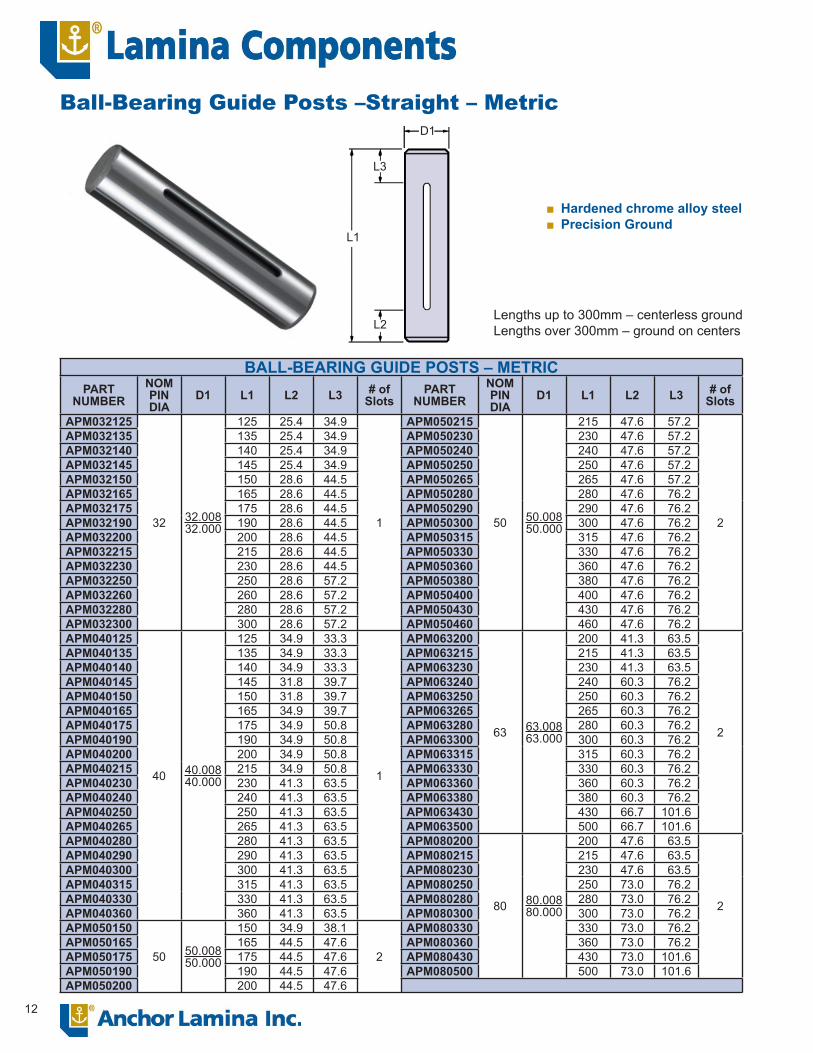
Ball-Bearing Guide Posts –Straight – Metric
Hardened chrome alloy steelPrecision Ground
■■
Lengths up to 300mm – centerless groundLengths over 300mm – ground on centers
D1
L1
L3
L2

13
BALL-BEARING GUIDE POSTS – METRIC – Tap FitPART
NUMBERNOMPINDIA
D1 D2 D3 L1 L3 L5 PARTNUMBER
NOMPINDIA
D1 D2 D3 L1 L3 L5
APGM032115
32 32.00832.000 32 40
115
30
85 APGM050165
50 50.00850.000 50 63
165
49
116APGM032120 120 90 APGM050170 170 121APGM032125 125 95 APGM050175 175 126APGM032135 135 105 APGM050180 180 131APGM032140 140 110 APGM050190 190 141APGM032145 145 115 APGM050195 195 146APGM032150 150 120 APGM050200 200 151APGM032165 165 135 APGM050215 215 166APGM032175 175 145 APGM050230 230 181APGM032190 190 160 APGM050240 240 191APGM032200 200 170 APGM050250 250 201APGM032215 215 185 APGM050260 260 211APGM032230 230 200 APGM050280 280 231APGM032250 250 220 APGM050290 290 241APGM032280 280 250 APGM050300 300 251APGM032300 300 270 APGM050315 315 266APGM040115
40 40.00840.000 40 48
115
36
79 APGM050330 330 281APGM040120 120 84 APGM050360 360 311APGM040125 125 89 APGM050380 380 331APGM040135 135 99 APGM050400 400 351APGM040140 140 104 APGM050430 430 381APGM040145 145 109 APGM050460 460 411APGM040150 150 114 APGM063200
63 63.00863.000 63 76
200
49
151APGM040165 165 129 APGM063215 215 166APGM040175 175 139 APGM063230 230 181APGM040190 190 154 APGM063250 250 201APGM040200 200 164 APGM063280 280 231APGM040215 215 179 APGM063300 300 251APGM040230 230 194 APGM063330 330 281APGM040240 240 204 APGM063360 360 311APGM040250 250 214 APGM063430 430 381APGM040260 260 224 APGM063500 500 451APGM040280 280 244 APGM080200
80 80.00880.000 80 93
200
62
138APGM040290 290 254 APGM080215 215 153APGM040300 300 264 APGM080230 230 168APGM040315 315 279 APGM080250 250 188APGM040330 330 294 APGM080280 280 218APGM040360 360 324 APGM080300 300 238APGM050140
50 50.00850.000 50 63
140
49
91 APGM080330 330 268APGM050145 145 96 APGM080360 360 298APGM050150 150 101 APGM080430 430 368APGM050155 155 106 APGM080500 500 438
Ball-Bearing Guide Posts – Tap Fit – Metric
D3D2
M8 x 1.25-20
Heavy-DutyClamp # X-40
L1
L3
L5
L2
D1
Large savings in maintenance, repair costs and downtime
Wide variety of sizesLong, trouble-free production runsHighest quality workmanship and materials“D2” dimension is fi nished ground
■
■■■■
6.35
4.75
14
FEED
FEED
FEED
FEED
FEED
FEED
FEED
120°
120°120°
90°
90°
45°
45°
45°
55°
35° 35°
35°
35°
10°70°
50°
40°
40°
40° 40° 5° 80°
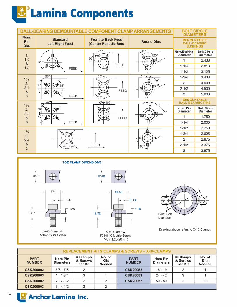
BALL-BEARING DEMOUNTABLE COMPONENT CLAMP ARRANGEMENTSNom.PinDia.
StandardLeft-Right Feed
Front to Back Feed(Center Post die Sets Round Dies
1,1¼&
1½
1¾,2,
2½&3
1¾,2,
2½&3
1¾,2,
2½&3
BOLT CIRCLEDIAMETERSDEMOUNTABLE BALL-BEARING
BUSHINGSNom. Bushing
DiameterBolt Circle Diameter
1 2.4381-1/4 2.8131-1/2 3.1251-3/4 3.438
2 4.0002-1/2 4.500
3 5.000DEMOUNTABLE
BALL-BEARING PINSNom. PinDiameter
Bolt Circle Diameter
1 1.7501-1/4 2.0001-1/2 2.2501-3/4 2.625
2 2.8752-1/2 3.375
3 3.875
REPLACEMENT KITS CLAMPS & SCREWS – X40-CLAMPS
PARTNUMBER
Nom PinDiameters
# Clamps& Screws
per Kit
No. of Kits
NeededPART
NUMBERNom Pin
Diameters# Clamps& Screws
per Kit
No. ofKits
NeededCSK200002 5/8 - 7/8 2 1 CSK20052 18 - 19 2 1CSK200003 1 - 1-3/4 3 1 CSK20053 24 - 42 3 1CSK200002 2 - 2-1/2 2 2 CSK20052 50 - 80 2 2CSK200003 3 - 4-1/2 3 2
TOE CLAMP DIMENSIONS
x-40-Clamp &5/16-18x3/4 Screw
X-40-Clamp &F010810 Metric Screw
(M8 x 1.25-20mm)
.688
.771
.320
.188.367
17.48
19.58
8.13
9.324.78
Bolt Circle Diameter
Drawing above refers to X-40 Clamps
15
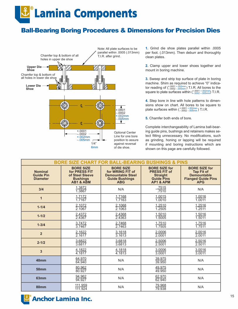
Ball-Bearing Boring Procedures & Dimensions for Precision Dies
Note: All plate surfaces to be parallel within .0005 (.013mm)T.I.R. after grind.Chamfer top & bottom of all
holes in upper die shoe
Upper Die Shoe
Chamfer top & bottom of all holes in lower die shoe
Lower Die Shoe
+.0001–.0002+.002mm–.005mm
+.0001–.0002+.002mm–.005mm
1/4”6mm
Optional Center Line for one bore position to assure against reversal of die shoe.
1. Grind die shoe plates parallel within .0005 per foot. (.013mm). Then deburr and thoroughly clean plates.
2. Clamp upper and lower shoes together and mount in boring machine.
3. Sweep and strip top surface of plate in boring machine. Shim as required to achieve “0” indica-tor reading of ( ) T.I.R. All bores to the square to plate surfaces within ( ) T.I.R.
4. Step bore in line with hole patterns to dimen-sions show on chart. All bores to be square to plate surfaces within ( ) T.I.R.
5. Chamfer both ends of bore.
Complete interchangeability of Lamina ball-bear-ing guide pins, bushings and retainers makes se-lect fi tting unnecessary. No modifi cations, such as grinding, honing or lapping will be required if mounting and boring instructions which are shown on this page are carefully followed.
+.0001 +.002mm–.0002 –.005mm
+.0001 +.002mm–.0002 –.005mm
+.0001 +.002mm–.0002 –.005mm
BORE SIZE CHART FOR BALL-BEARING BUSHINGS & PINS
NominalGuide PinDiameter
BORE SIZEfor PRESS FITof Steel Sleeve
BushingsAB1 & ABM
BORE SIZE for WRING FIT of
Demountable SteelGuide Bushings
ABG
BORE SIZE for PRESS FIT of
Straight Guide PinsAP1 & APM
BORE SIZE forTap Fit of
DemountableFlanged Guide Pins
APG
3/4 1.38721.3867 N/A .7515
.7510 N/A
1 1.71721.7167
1.71681.7163
1.00151.0010
1.00161.0011
1-1/4 2.10722.1067
2.10682.1063
1.25101.2505
1.25161.2511
1-1/2 2.43722.4367
2.43682.4363
1.50101.5005
1.50161.5011
1-3/4 3.74723.7467
2.74682.7463
1.75101.7505
1.75161.7511
2 2.16222.1617
3.16183.1613
2.00062.0001
2.00162.0011
2-1/2 3.68223.6817
3.68183.6813
2.50062.5001
2.50162.5011
3 4.18224.1817
4.18184.1813
3.00063.0001
3.00163.0011
40mm 64.97064.940 N/A 39.975
39.950 N/A
50mm 80.96280.927 N/A 49.975
49.950 N/A
63mm 94.96294.927 N/A 62.970
62.940 N/A
80mm 111.959111.924 N/A 79.968
79.938 N/A

Lamina Components38505 Country Club Drive, Suite 100
Farmington Hills, Michigan 48331 USATel: 248-489-9122, 800-652-6462Fax: 248-553-6842, 800-406-4410
E-mail: [email protected]
002-0605-5m
Minimum Shut Height
Maximum Post Length
Ball-Bearing Component Installation InstructionsFigure 1
Punch Holder in contact with Bushing Punch and die life depleted
Figure 1 (Minimum Shut Height) deter-mines maximum guide post length and maximum bushing height. This will pre-vent post bottoming on bolster at mini-mum shut height if nominal post length is same as minimum shut height.
Figure 2
MaximumShut Height
New Punch and Die
The maximum shut height added to the stroke equals the maximum open height (Figure 3 ) indicating the minimum en-gagement for the guide post in the required bushing. It is considered ideal for the min-imum engagement to be at least 3/4”. If it is less than 3/4”, however, the arrange-ment shown in Figure 4 is recommended.
Figure 3
Stroke
Maximum Open Height
Minimum Engagement
3/4”
When required strokes are longer than normal, guide post and retainer, if nec-essary, may be totally disengaged from bushing on the upward travel, provided (A) operation is vertical, (B) operation is limited to no more than 150 strokes per minute, (C) the ram and gib alignment of the press are accurate.
Figure 4
The bushing must always be engaged by the guide post minimum of 3/4” if the operation is included or if speed surpasses 150 strokes per minute. The guide post bushing must engage the retainer during the entire operation, or what is known as full contact pre-load operation.
GENERAL INFORMATION SPECIFICATIONS
1. The ball-bearing retainer travels half the distance the pin travels or one-half the stroke length.
2. The maximum post length equals(=) minimum shut height minus (-) 1/4” Fig-ure 1. If post length should be greater than minimum shut height it will be nec-essary to provide clearance for projecting post when press is at bottom of stroke.
3. Maximum straight sleeve length Figure 1 equals (=) minimum shut height minus (-) punch holder thickness minus (-) 1/4”. Select nearest standard length.
4. Maximum retainer length equals (=) bushing length minus (-) 1/2”.
Post slot lengths available upon request.
Keeping in mind that only a small part of the stroke on most dies actually does the work, when conditions shown in Figure 4 are acceptable, together with conditions shown in Figures 1 and 2, there is no need to be concerned with the full length of the stroke and maximum open height.
D
1/4”
L