Bale Processor Operator's & Parts Manual · Implement Tongue ... The telescoping tubes must overlap...
74
BALE KING 5100/5100TR Bale Processor Operator's & Parts Manual Last Updated: August 11, 2015 Bridgeview Manufacturing Inc. P.O. Box 4 Gerald, Saskatchewan, Canada S0A 1B0 Phone: 1-306-745-2711 Fax: 1-306-745-3364 Email: [email protected] www.bridgeviewmanufacturing.com
Transcript of Bale Processor Operator's & Parts Manual · Implement Tongue ... The telescoping tubes must overlap...

BALE KING 5100/5100TR Bale Processor
Operator's & Parts Manual
Last Updated: August 11, 2015
Bridgeview Manufacturing Inc. P.O. Box 4
Gerald, Saskatchewan, Canada S0A 1B0
Phone: 1-306-745-2711 Fax: 1-306-745-3364
Email: [email protected] www.bridgeviewmanufacturing.com
Bridgeview Manufacturing Inc. ii
The Serial Number is located the front tub panel, next to the operator manual box.
Your Authorized Dealer
Your Serial Number
Bridgeview Manufacturing Inc. iii
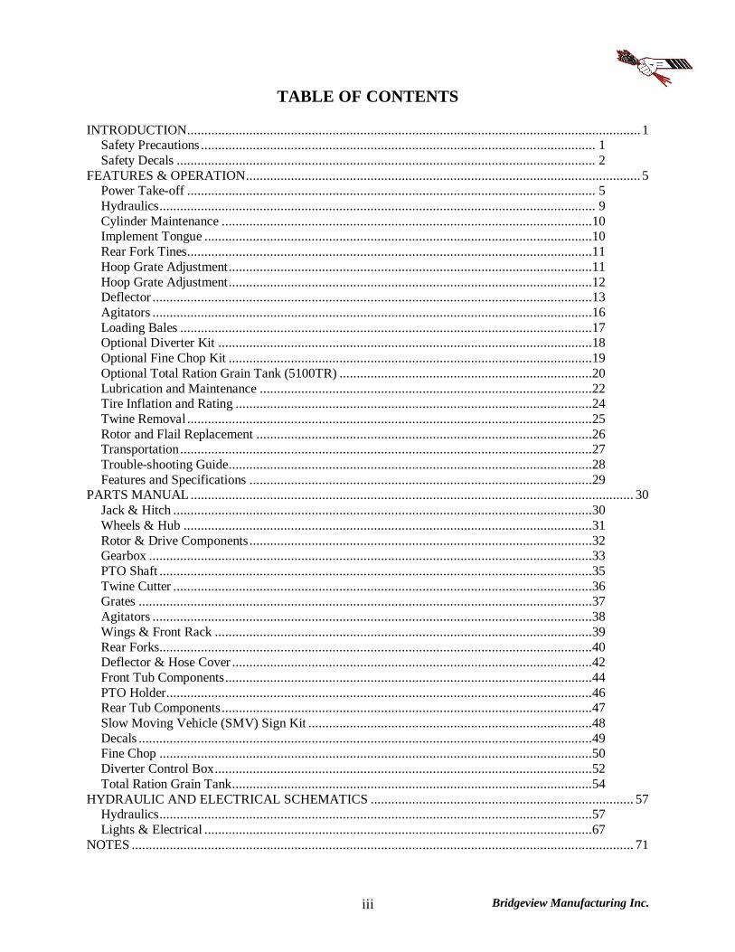
TABLE OF CONTENTS INTRODUCTION................................................................................................................................... 1
Safety Precautions .................................................................................................................. 1 Safety Decals ......................................................................................................................... 2
FEATURES & OPERATION.................................................................................................................. 5 Power Take-off ...................................................................................................................... 5 Hydraulics.............................................................................................................................. 9 Cylinder Maintenance ...........................................................................................................10 Implement Tongue ................................................................................................................10 Rear Fork Tines.....................................................................................................................11 Hoop Grate Adjustment.........................................................................................................11 Hoop Grate Adjustment.........................................................................................................12 Deflector ...............................................................................................................................13 Agitators ...............................................................................................................................16 Loading Bales .......................................................................................................................17 Optional Diverter Kit ............................................................................................................18 Optional Fine Chop Kit .........................................................................................................19 Optional Total Ration Grain Tank (5100TR) .........................................................................20 Lubrication and Maintenance ................................................................................................22 Tire Inflation and Rating .......................................................................................................24 Twine Removal.....................................................................................................................25 Rotor and Flail Replacement .................................................................................................26 Transportation.......................................................................................................................27 Trouble-shooting Guide.........................................................................................................28 Features and Specifications ...................................................................................................29
PARTS MANUAL ................................................................................................................................ 30 Jack & Hitch .........................................................................................................................30 Wheels & Hub ......................................................................................................................31 Rotor & Drive Components...................................................................................................32 Gearbox ................................................................................................................................33 PTO Shaft .............................................................................................................................35 Twine Cutter .........................................................................................................................36 Grates ...................................................................................................................................37 Agitators ...............................................................................................................................38 Wings & Front Rack .............................................................................................................39 Rear Forks.............................................................................................................................40 Deflector & Hose Cover ........................................................................................................42 Front Tub Components..........................................................................................................44 PTO Holder...........................................................................................................................46 Rear Tub Components...........................................................................................................47 Slow Moving Vehicle (SMV) Sign Kit ..................................................................................48 Decals ...................................................................................................................................49 Fine Chop .............................................................................................................................50 Diverter Control Box.............................................................................................................52 Total Ration Grain Tank........................................................................................................54
HYDRAULIC AND ELECTRICAL SCHEMATICS ............................................................................ 57 Hydraulics.............................................................................................................................57 Lights & Electrical ................................................................................................................67
NOTES ................................................................................................................................................. 71
Bridgeview Manufacturing Inc. 1
INTRODUCTION Thank you for purchasing a Bale King bale processor. With the proper operation and service as
outlined in this manual, the Bale King will provide you with years of trouble free operation.
This is a complete safety, operation and parts manual for the Bale King 5100. The
manual covers in detail how to safely and effectively use your new processor. The procedures
outlined in this manual should be followed to ensure safe operation and longevity of your
machine. The parts manual covers all parts you may need to order in case of accident or
breakdown. Please read completely through this manual before beginning operation of your new
machine.
Safety Precautions The following safety precautions MUST be followed to ensure safe operation of the Bale King Bale processor.
ALWAYS turn OFF the tractor when leaving the operating platform.
DO NOT stand in front of the discharge chute while the machine is running.
DO NOT walk or move under the bale forks when they are in the upward position,
unless the cylinder safety lock is in place.
DO NOT enter the machine while in operation.
DO NOT clean machine while in operation.
DO NOT stick any device into the machine to clear debris while the machine is in operation.
ALWAYS turn off the machine when cleaning the machine, removing twine, or
hooking/unhooking the machine
ALWAYS use safety chain when towing the machine on the highway.
DO NOT operate if any part of the PTO safety shielding is missing or is not secured.
Bridgeview Manufacturing Inc. 2
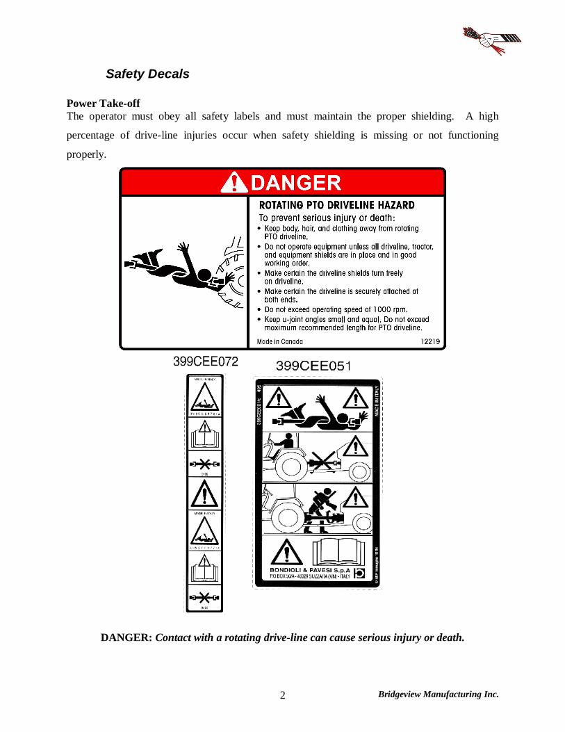
Safety Decals Power Take-off The operator must obey all safety labels and must maintain the proper shielding. A high
percentage of drive-line injuries occur when safety shielding is missing or not functioning
properly.
DANGER: Contact with a rotating drive-line can cause serious injury or death.
Bridgeview Manufacturing Inc. 3
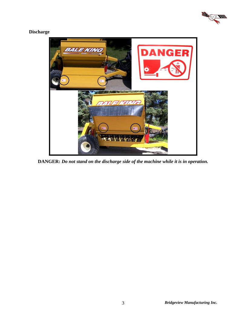
Discharge
DANGER: Do not stand on the discharge side of the machine while it is in operation.
Bridgeview Manufacturing Inc. 4
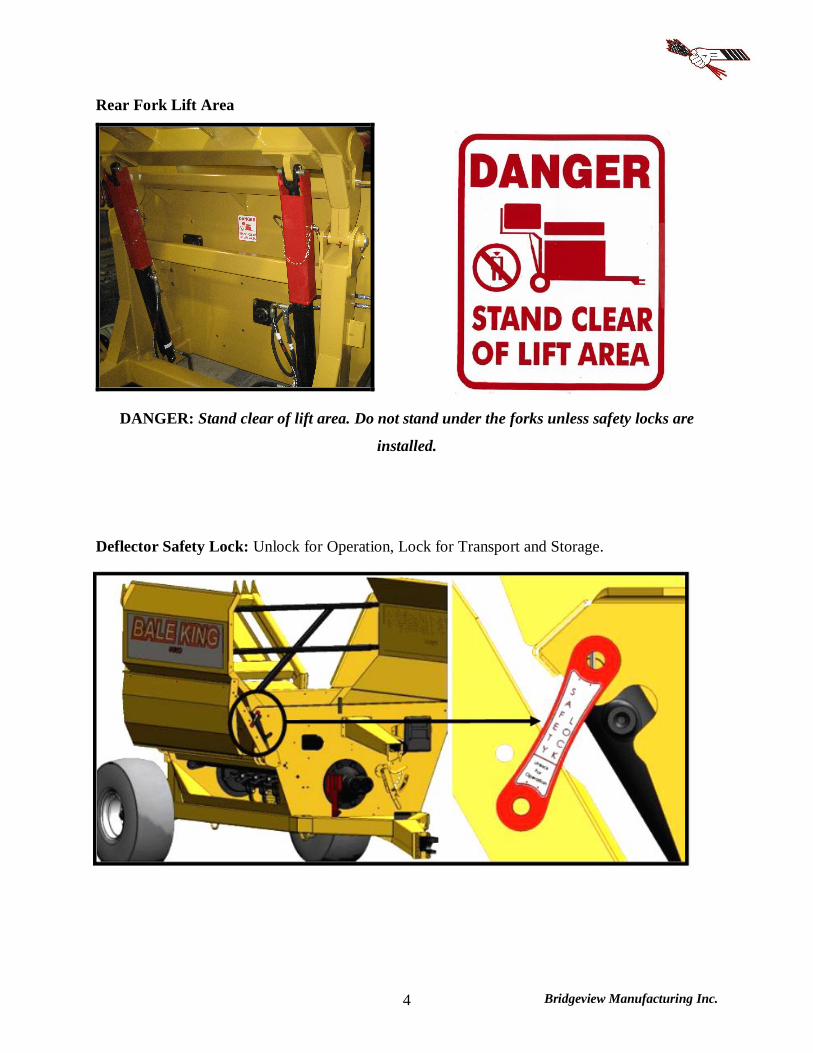
Rear Fork Lift Area
DANGER: Stand clear of lift area. Do not stand under the forks unless safety locks are
installed.
Deflector Safety Lock: Unlock for Operation, Lock for Transport and Storage.

Bridgeview Manufacturing Inc. 5
FEATURES & OPERATION
Power Take-off The Bale King bale processor has a PTO shaft which is splined on both ends. The
implement end uses a 1-3/4"-20 spline with wedge lock bolts. Install onto the gearbox and
tighten the wedge bolts. The bolts should be torqued to 160 ft-lb and re-torqued after 8 hrs of
use.
The tractor end comes standard with a 1-3/8"-21 spline quick detach constant velocity
joint. An optional 1-3/4"-20 spline yoke is available through your Bale King dealer.
The Bale King processor is designed to use a minimum of 75 HP. The drive shaft is
shear-bolt protected. The machine must be operated at 1000 PTO RPM.
NOTE: Spread yokes and twisted drive shafts are signs of OVERLOAD, not a manufacturer’s defect and therefore not covered by warranty.
DO NOT operate the machine using a spline adaptor. Use of adaptors will void warranty due to damage caused to the tractor PTO, PTO driveshaft, or implement.
DO NOT operate at 540 rpm, or use any kind of adaptor to connect to a 540 rpm spline.
Always ensure that the PTO shaft is attached securely to the tractor. When the processor
is not hooked to the tractor, store the shaft on the PTO holder.
DO NOT transport the processor without securing the PTO shaft. It may bounce off the holder and be damaged.
Always ensure that the drawbar is adjusted to 16” from the end of the tractor PTO shaft
to the center of the hole in the drawbar.
Operation
To engage the rotor for processing a bale, be sure the PTO shaft is properly connected to the
tractor. Engage the PTO at idle. After the PTO is fully engaged, increase PTO speed until it
reaches 1000 RPM.
The processor must not run at any speed less than 1000 PTO RPM as it may result in the
flails springing back against the rotor after they come in contact with the bale. This “backslap”
Bridgeview Manufacturing Inc. 6
may cause flails to fatigue and excessive vibration which may cause the bearings to fail. Bales
may be dumped into the tub while the rotor is stopped or while it is running.
Shear Bolt
All new Bale King processors are equipped with a shear bolt clutch located at the implement
end of the PTO shaft. The correct size shear bolt is 3/8 x 2” Grade 5. Any other size or grade
will damage the shear assembly. Spare shear bolts are shipped with each new machine and are
stored along the front top lip of the tub.
If your shear bolt is shearing excessively you may be over-loading the machine. If this
occurs raise the grate assembly to make the machine less aggressive, or roll the bale more
slowly. Always ensure that your machine is running at 1000 PTO RPM.
NOTE: Please consult your local dealer to help pinpoint any problems.
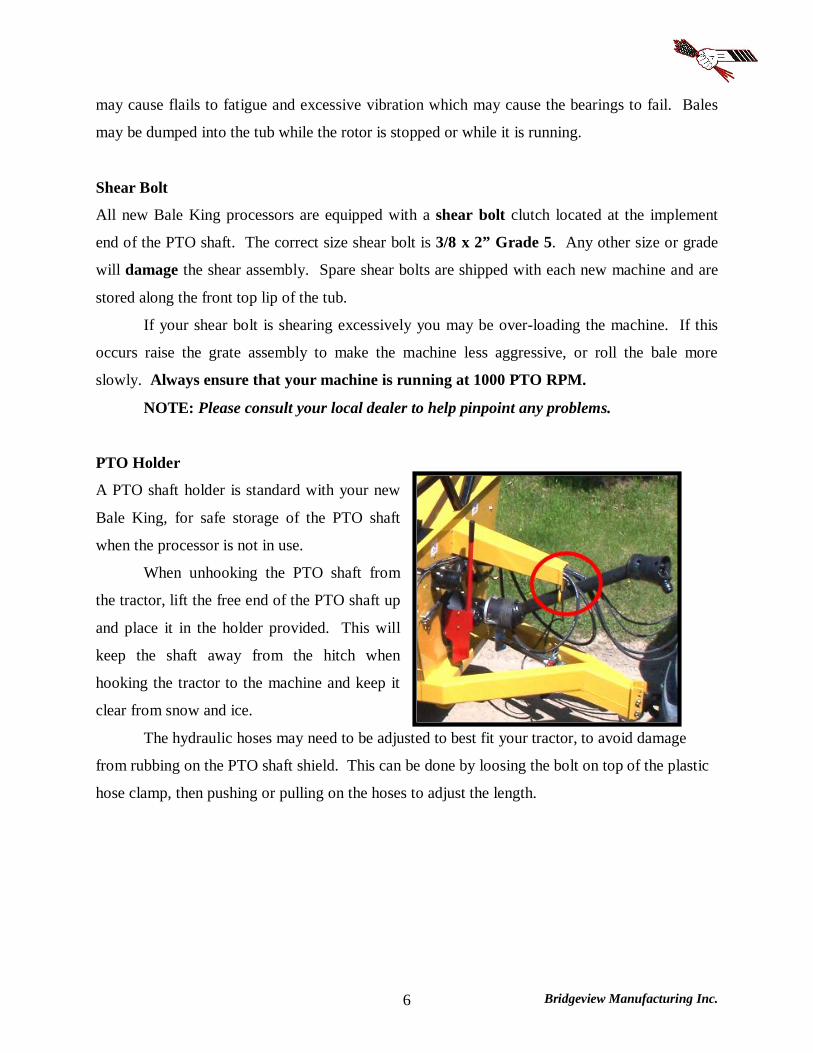
PTO Holder
A PTO shaft holder is standard with your new
Bale King, for safe storage of the PTO shaft
when the processor is not in use.
When unhooking the PTO shaft from
the tractor, lift the free end of the PTO shaft up
and place it in the holder provided. This will
keep the shaft away from the hitch when
hooking the tractor to the machine and keep it
clear from snow and ice.
The hydraulic hoses may need to be adjusted to best fit your tractor, to avoid damage
from rubbing on the PTO shaft shield. This can be done by loosing the bolt on top of the plastic
hose clamp, then pushing or pulling on the hoses to adjust the length.
Bridgeview Manufacturing Inc. 7
PTO Use and Maintenance
Shut OFF the tractor engine and remove the key before doing any maintenance on the machine.
Use ONLY genuine Weasler parts when replacing any worn or damaged PTO components.
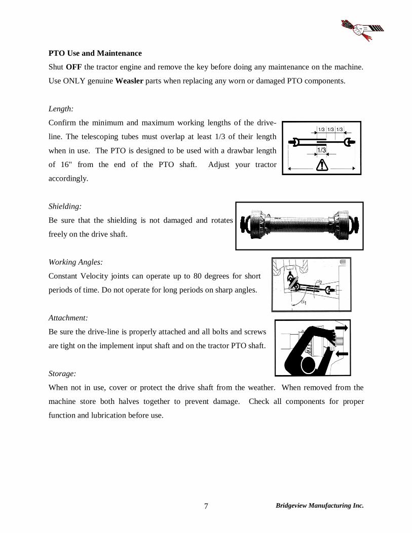
Length:
Confirm the minimum and maximum working lengths of the drive-
line. The telescoping tubes must overlap at least 1/3 of their length
when in use. The PTO is designed to be used with a drawbar length
of 16" from the end of the PTO shaft. Adjust your tractor
accordingly.
Shielding:
Be sure that the shielding is not damaged and rotates
freely on the drive shaft.
Working Angles:
Constant Velocity joints can operate up to 80 degrees for short
periods of time. Do not operate for long periods on sharp angles.
Attachment:
Be sure the drive-line is properly attached and all bolts and screws
are tight on the implement input shaft and on the tractor PTO shaft.
Storage:
When not in use, cover or protect the drive shaft from the weather. When removed from the
machine store both halves together to prevent damage. Check all components for proper
function and lubrication before use.

Bridgeview Manufacturing Inc. 8
BEFORE ATTEMPTING ANY REPAIR PROCEDURES, ALWAYS USE APPROPRIATE EQUIPMENT SUCH AS
SAFETY GLASSES, SAFETY SHOES, AND GLOVES
Shield Removal:
To remove the shield, pop out the red snap, then rotate
the guard on the bearing to line up the three tabs with
the openings and pull it off away from the knuckle
joint.
Remove the nylon bearing from the shaft by spreading
it open.
Shield Assembly:
Be sure to lubricate the groove in the inner yokes where the shield
bearing rides. Reinstall shields in the reverse order that they were
removed.

Bridgeview Manufacturing Inc. 9
Hydraulics WARNING: Pressurized hydraulic fluid can
cause serious injury.
When working with hydraulic equipment,
eye and hand protection should be worn.
Do not test for leaks with bare hands.
Relieve any pressure before removing a
hose or fitting.
Never work under components raised by hydraulic equipment unless supported externally.
There are three sets of hydraulic hoses to connect to the tractor. Each hose has a coloured marker
to identify its function. They should be connected at best convenience for the tractor's controls.
Note that the hoses are paired by colour and the following tables show the operation when
pushing oil into the hose with the longer marker.
5100 - 3 Remotes
Hose Marker Function
Long Red Turn agitators clockwise
Long Blue Lift rear fork
Long Yellow Lift discharge deflector
An optional diverter kit (BMI # 25091) is available to allow the Bale King 5100 to run using
only two sets of hoses. The function is then determined by a control box, mounted in the cab of
the tractor.
5100 - 2 Remotes
Hose Marker Function
Long Red Turn agitators clockwise
Long Blue Lift rear fork or deflector
Always set the tractor's hydraulic flow at a lower rate and adjust it upward until the desired speed
is reached. Excessive oil flow may damage the flow divider cartridge.

Bridgeview Manufacturing Inc. 10
Cylinder Maintenance The hydraulic cylinders are easily removed for repair or maintenance
simply by:
Lowering the fork (or deflector) to the down position and
unhooking the hydraulic lines. Be sure there is no pressure on
the lines and mark the line locations so there is no confusion
when reinstalling the cylinders. Check hydraulic schematics.
Removing the cotter pin closest to the frame of the machine and
sliding the cylinder pins out
To reinstall, reverse the removal procedure
NOTE: Always cover exposed cylinder shafts with grease to avoid rusting of shafts if the unit
is not used for extended periods of time. Rusted cylinder shafts are NOT covered by warranty
NOTE: Check all hoses and fittings periodically for leaks. Tighten or replace any dripping
components or any worn out hoses.
Implement Tongue The adjustable hitch on the Bale King features a cast single
tongue with hammer strap insert. This allows for use with
tractors equipped with a hammer strap or with a single
drawbar. It also allows the machine to move independently
over rough terrain without bending the draw pin.
Make sure that the drawbar is set to 16 inches behind
the PTO shaft for proper PTO length.
Adjust the hitch height to match the drawbar height and allow the machine to sit level.
DO NOT install the insert if using a tractor with a hammer strap as this will bend the
hitch pin
NOTE: Make sure that the jack in on the outside stub for lifting, and the inside stub during
transport. DO NOT lift the machine with the jack on the inside stub.
Bridgeview Manufacturing Inc. 11
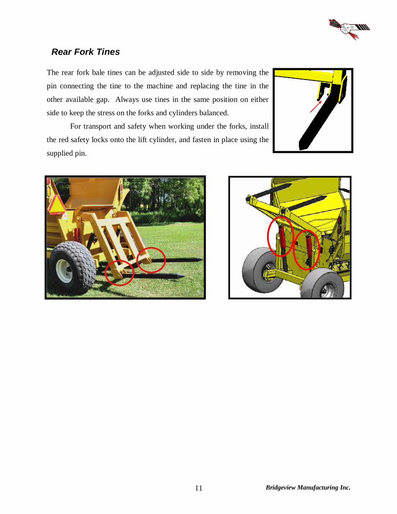
Rear Fork Tines The rear fork bale tines can be adjusted side to side by removing the
pin connecting the tine to the machine and replacing the tine in the
other available gap. Always use tines in the same position on either
side to keep the stress on the forks and cylinders balanced.
For transport and safety when working under the forks, install
the red safety locks onto the lift cylinder, and fasten in place using the
supplied pin.
Bridgeview Manufacturing Inc. 12
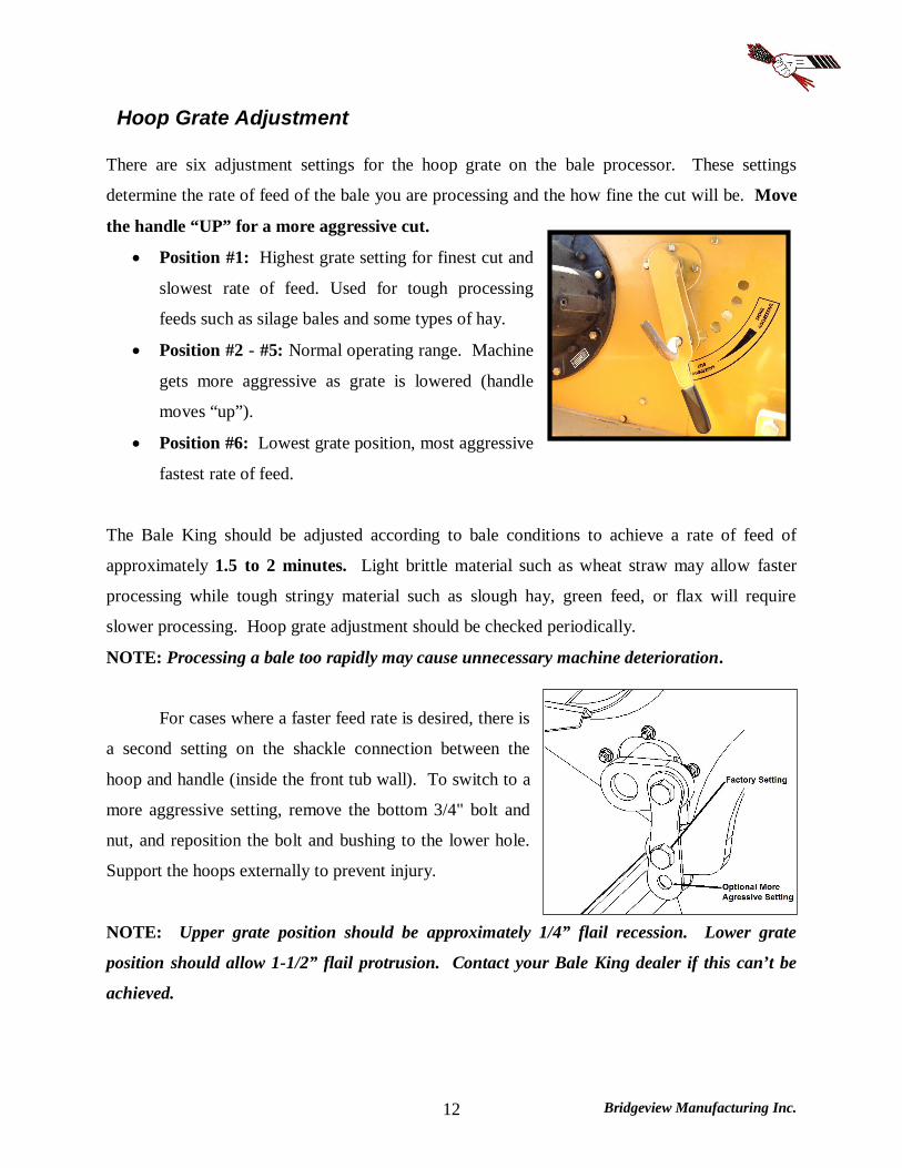
Hoop Grate Adjustment There are six adjustment settings for the hoop grate on the bale processor. These settings
determine the rate of feed of the bale you are processing and the how fine the cut will be. Move
the handle “UP” for a more aggressive cut.
Position #1: Highest grate setting for finest cut and
slowest rate of feed. Used for tough processing
feeds such as silage bales and some types of hay.
Position #2 - #5: Normal operating range. Machine
gets more aggressive as grate is lowered (handle
moves “up”).
Position #6: Lowest grate position, most aggressive
fastest rate of feed.
The Bale King should be adjusted according to bale conditions to achieve a rate of feed of
approximately 1.5 to 2 minutes. Light brittle material such as wheat straw may allow faster
processing while tough stringy material such as slough hay, green feed, or flax will require
slower processing. Hoop grate adjustment should be checked periodically.
NOTE: Processing a bale too rapidly may cause unnecessary machine deterioration.
For cases where a faster feed rate is desired, there is
a second setting on the shackle connection between the
hoop and handle (inside the front tub wall). To switch to a
more aggressive setting, remove the bottom 3/4" bolt and
nut, and reposition the bolt and bushing to the lower hole.
Support the hoops externally to prevent injury.
NOTE: Upper grate position should be approximately 1/4” flail recession. Lower grate
position should allow 1-1/2” flail protrusion. Contact your Bale King dealer if this can’t be
achieved.

Bridgeview Manufacturing Inc. 13
Deflector The Bale King 5100 is equipped with a hydraulic side deflector to change the discharge distance
and distribution. It also comes with a flipping rubber flap for superior control of the spread
pattern.
Moving the deflector to the down position and flipping the rubber down (above left) will allow
the hay to be laid in a windrow, or bunk feeder. Swinging the deflector up will allow you to
spread straw out over a large area. If you also flip the rubber up (above right), you will be able
to "fine tune" the discharge, to control the height and distance.
To flip the rubber, simply pull on the handle and swing into position. Then push the
handle so that the tabs catch in the notches and lock into place.

Bridgeview Manufacturing Inc. 14
The Bale King 5100 deflector comes with the additional feature of adjustable width:
First move the deflector to its lowest position.
Remove the seven bolts (2 front, 3 top, 2 rear) connecting the inner and outer deflector
pieces.
Slide the outer deflector to the desired width and replace the bolts.
There are three different deflector length settings to accommodate your desired width:
Bunk Feeding Width (Distance from Tire)
Transport Width Total (RHS, LHS)
Folded N/A 8'-6" (4'-3", 4'-3") Short 28 Inches 9'-4" (5'-1", 4'-3") Medium 32 Inches 9'-8" (5'-5", 4'-3") Long 35 Inches 9'-10" (5'-7", 4'-3")
NOTE: Use only the medium and short settings unless required due to tractor width.
For transport and storage, the deflector lock should be put in place by swinging the lock as
shown and fastening with a lynch pin.
Bridgeview Manufacturing Inc. 15
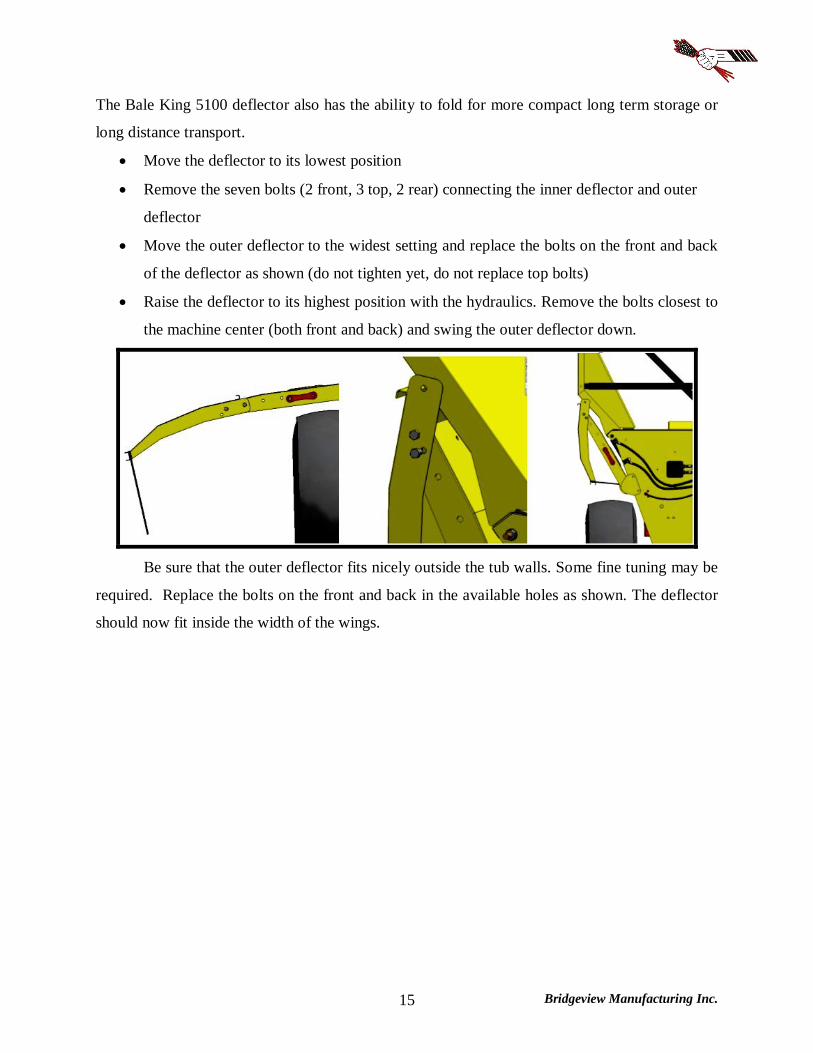
The Bale King 5100 deflector also has the ability to fold for more compact long term storage or
long distance transport.
Move the deflector to its lowest position
Remove the seven bolts (2 front, 3 top, 2 rear) connecting the inner deflector and outer
deflector
Move the outer deflector to the widest setting and replace the bolts on the front and back
of the deflector as shown (do not tighten yet, do not replace top bolts)
Raise the deflector to its highest position with the hydraulics. Remove the bolts closest to
the machine center (both front and back) and swing the outer deflector down.
Be sure that the outer deflector fits nicely outside the tub walls. Some fine tuning may be
required. Replace the bolts on the front and back in the available holes as shown. The deflector
should now fit inside the width of the wings.
Bridgeview Manufacturing Inc. 16
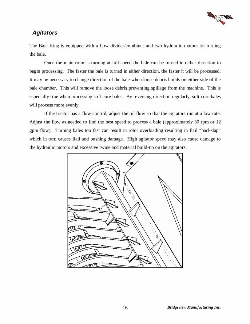
Agitators The Bale King is equipped with a flow divider/combiner and two hydraulic motors for turning
the bale.
Once the main rotor is turning at full speed the bale can be turned in either direction to
begin processing. The faster the bale is turned in either direction, the faster it will be processed.
It may be necessary to change direction of the bale when loose debris builds on either side of the
bale chamber. This will remove the loose debris preventing spillage from the machine. This is
especially true when processing soft core bales. By reversing direction regularly, soft core bales
will process more evenly.
If the tractor has a flow control, adjust the oil flow so that the agitators run at a low rate.
Adjust the flow as needed to find the best speed to process a bale (approximately 30 rpm or 12
gpm flow). Turning bales too fast can result in rotor overloading resulting in flail “backslap”
which in turn causes flail and bushing damage. High agitator speed may also cause damage to
the hydraulic motors and excessive twine and material build-up on the agitators.

Bridgeview Manufacturing Inc. 17
Loading Bales
When loading Bales into your Bale King bale processor, the following procedure should be
followed:
Position the tractor and the Bale King so as to be lined up to back straight into the row of
bales.
When close to the bale, lower the forks completely (you will feel a light vibration as the
forks bottom out against the frame.)
Back completely under the first bale.
Allow the tractor to move forward while lifting the bale, because the bale fork moves
away from the machine while loading.
If you are loading from the same row you can dump the bale into the machine and back
straight into the second bale. If you are going to a different stack for the second bale only
raise the first bale enough to clear the ground. Move to the next row and align the
machine to the bale before dumping the bale into the tub. This gives you good visibility
to line up to the second bale.
Once you have the first bale in the tub and the second bale on the forks, raise the bale
fork about 1/4 of the way up. You can now transport to your feeding or bedding area to
begin processing.
Note: Carry the bale as low as possible to lessen the stress on the cylinder shafts. Carrying
the bale too high may bend hydraulic cylinder shafts.
When the first bale has been processed, it is common practice to leave the rotor running
at full speed when loading the second bale into the bale chamber from the rear forks.

Bridgeview Manufacturing Inc. 18
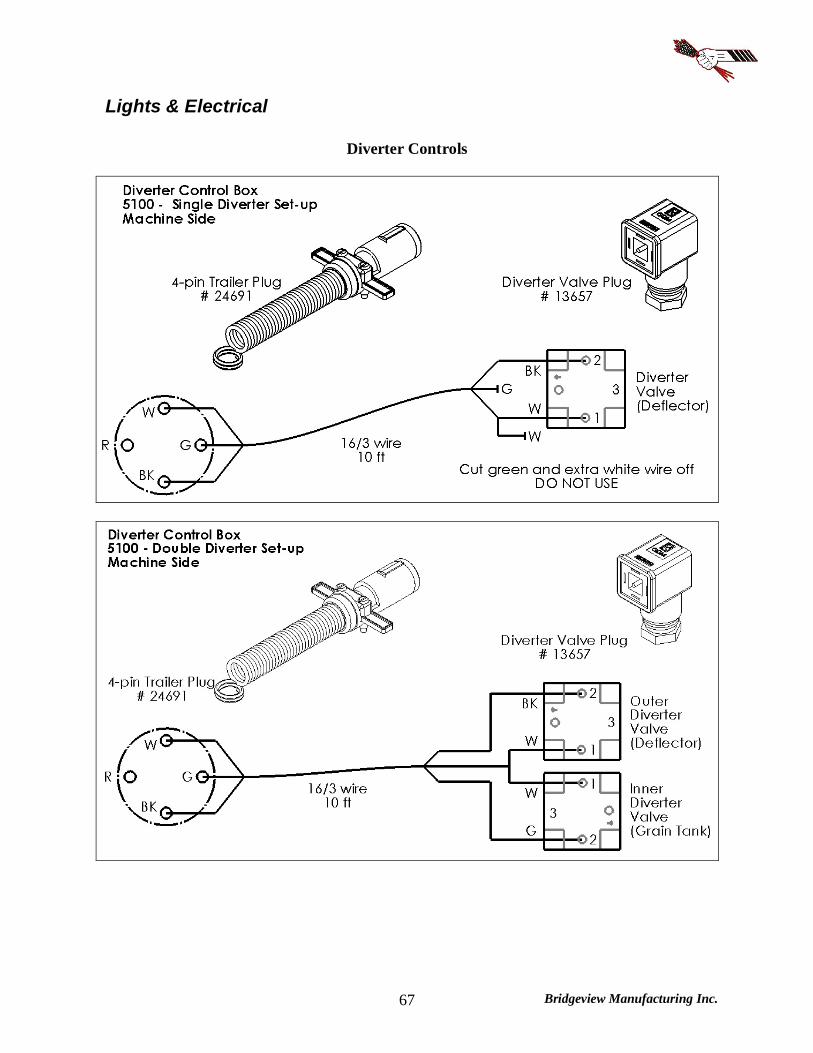
Optional Diverter Kit The Bale King 5100 processor has an optional diverter kit (BMI # 25091) which allows it to
operate using only 2 hydraulic remotes. The fork and deflector functions are then controlled by a
cab-mounted switch box. This box must be wired up to the tractor's electrical system.
The diverter kit also features a pilot operated check valve to ensure that the deflector will not fall
down due to leaking across the valve.
A 4-pin plug is used to power the diverter valve on the processor. If no power is supplied, the
hydraulics will still control the rear forks, but the deflector will not be functional. If the switch
in the tractor is activated, the deflector can be controlled. On 5100TR machines, this box can
also control grain flow ("Feed").

Bridgeview Manufacturing Inc. 19
Optional Fine Chop Kit
The Bale King 5100 processor has an optional fine chop knife kit (BMI # 22139) available to go
into the lower tub area. This option is available if you require a finer cut on the material which
you are processing such as slough hay and silage bales.
It is recommended that the knives be lowered when bedding straw as it will affect your
spread pattern. Adjust the machine as needed.
There are two settings for the fine chop, depending on how fine you wish to cut the
material. These settings achieved by pulling on the handle (towards the back of the machine),
then selecting the desired hole.

Bridgeview Manufacturing Inc. 20
Optional Total Ration Grain Tank (5100TR)
The Bale King 5100 has an available 40 bushel grain tank, which allows grain to be discharged
on top of a windrow of processed hay, or independently out the right side of the machine. This
bolt-on kit changes the processor to a 5100TR (Total Ration).
The tank is located on the left side of the machine and features a large opening, 5 ft off
the ground for easy filling. A flow control valve allows you to adjust the speed of the augers so
that you can meter the grain flow for different situations. It is recommended to determine your
desired rate based on driving speed and the flow rate of the tractor. Setting the valve to "0" will
give no grain, while setting it to "10" will be full speed.
The grain tank has the option of running using two, three, or four sets of hoses. Each
hose has a coloured marker to identify its function. They should be connected at best
convenience for the tractor's controls. Note that the hoses are paired by colour and the following
tables show the operation when pushing oil into the hose with the longer marker.

Bridgeview Manufacturing Inc. 21
5100TR - 4 Remotes Set-up
Hose Marker Function
Long Red Turn agitators clockwise
Long Blue Lift rear fork
Long Yellow Lift discharge deflector
Long Green Discharge grain
5100TR - 3 Remote Set-up
Hose Marker Function
Long Red Turn agitators clockwise
Long Blue Lift rear fork or deflector
Long Green Discharge grain
5100TR - 2 Remote Set-up
Hose Marker Function
Long Red Turn agitators clockwise
Long Blue Lift rear fork or deflector, or discharge grain
If a Total Ration grain tank is installed with a fine chop kit, an adaptor (BMI # 22042) is
available to move the handle to the front of the tub.
Cleanout doors are located at the bottom end of both the cross-auger, and the grain tank. It is
recommended that both be cleaned out at the end of every season.
Bridgeview Manufacturing Inc. 22
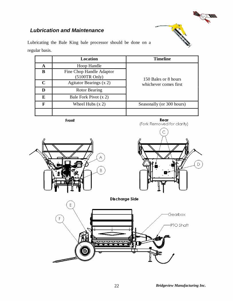
Lubrication and Maintenance Lubricating the Bale King bale processor should be done on a
regular basis.
Location Timeline A Hoop Handle B Fine Chop Handle Adaptor
(5100TR Only) C Agitator Bearings (x 2) D Rotor Bearing E Bale Fork Pivot (x 2)
150 Bales or 8 hours whichever comes first
F Wheel Hubs (x 2) Seasonally (or 300 hours)
Bridgeview Manufacturing Inc. 23
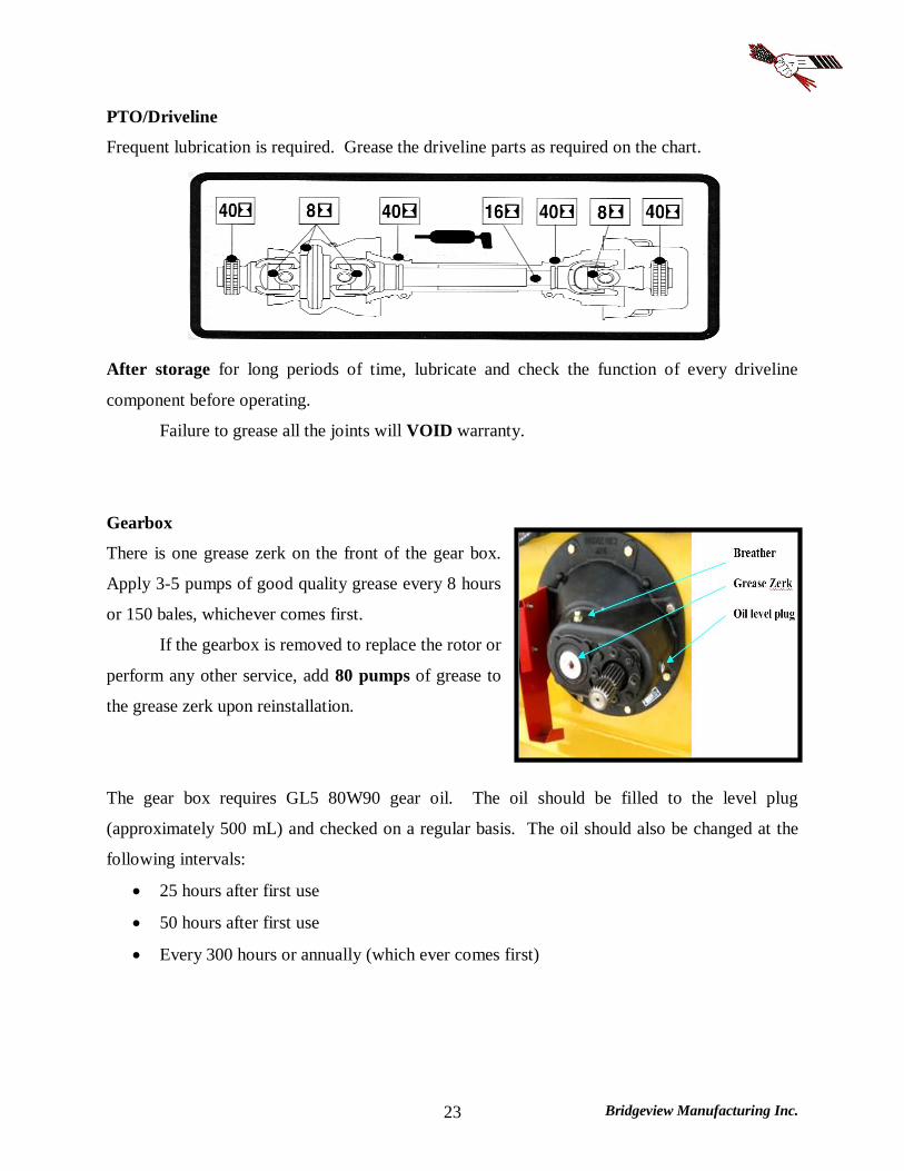
PTO/Driveline
Frequent lubrication is required. Grease the driveline parts as required on the chart.
After storage for long periods of time, lubricate and check the function of every driveline
component before operating.
Failure to grease all the joints will VOID warranty.
Gearbox
There is one grease zerk on the front of the gear box.
Apply 3-5 pumps of good quality grease every 8 hours
or 150 bales, whichever comes first.
If the gearbox is removed to replace the rotor or
perform any other service, add 80 pumps of grease to
the grease zerk upon reinstallation.
The gear box requires GL5 80W90 gear oil. The oil should be filled to the level plug
(approximately 500 mL) and checked on a regular basis. The oil should also be changed at the
following intervals:
25 hours after first use
50 hours after first use
Every 300 hours or annually (which ever comes first)
Bridgeview Manufacturing Inc. 24
Tire Inflation and Rating Wheel bearings should be inspected annually for adjustment and lubricated annually. Inspect
more often for extensive traveling.
To tighten the wheel bearings, lift up each wheel (one at a time) until the wheel spins
freely.
Remove dust cap and the cotter pin which retains the castle nut.
Tighten the nut until the wheel will rotate approximately two turns when given a firm
spin.
Align castle nut to closest hole and insert the cotter pin.
Pack hub full of grease and reinstall the dust cap.
Proper tire inflation will help to alleviate puncture problems when towing and operating on
rough terrain.
Check for proper tire inflation 24 psi
Replace any damaged or worn tires 16Lx16.1 6-ply
Check and tighten wheel bolts on a regular basis 125 ft.lb
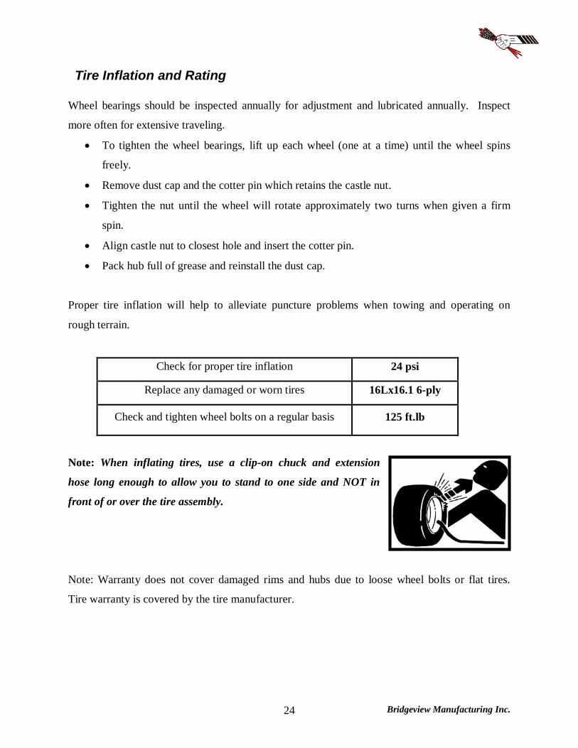
Note: When inflating tires, use a clip-on chuck and extension
hose long enough to allow you to stand to one side and NOT in
front of or over the tire assembly.
Note: Warranty does not cover damaged rims and hubs due to loose wheel bolts or flat tires.
Tire warranty is covered by the tire manufacturer.
Bridgeview Manufacturing Inc. 25
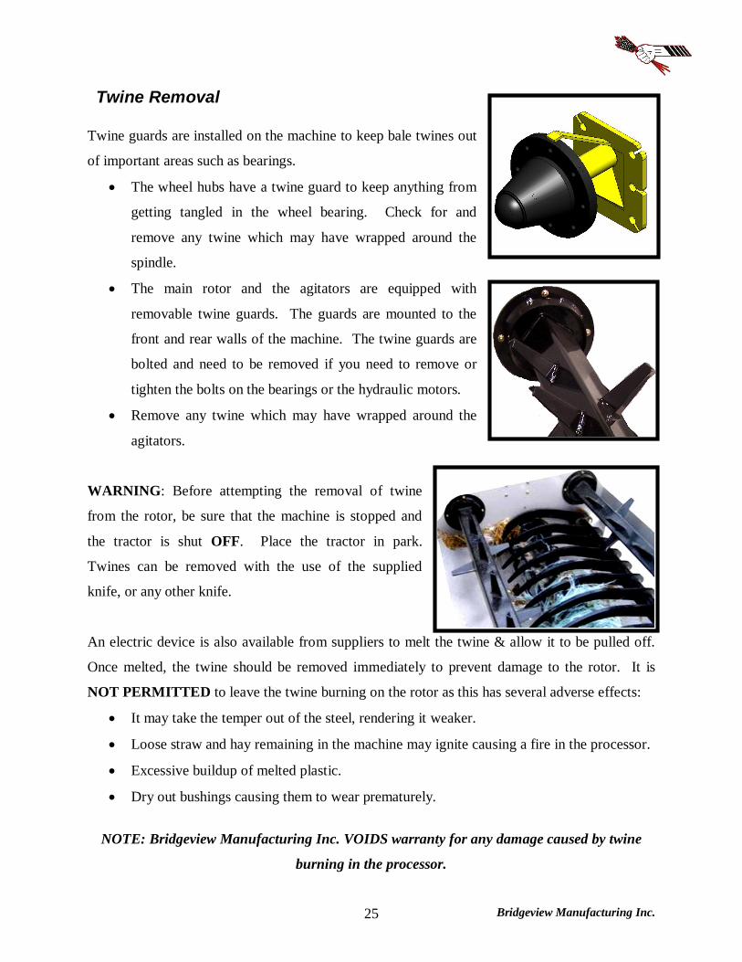
Twine Removal Twine guards are installed on the machine to keep bale twines out
of important areas such as bearings.
The wheel hubs have a twine guard to keep anything from
getting tangled in the wheel bearing. Check for and
remove any twine which may have wrapped around the
spindle.
The main rotor and the agitators are equipped with
removable twine guards. The guards are mounted to the
front and rear walls of the machine. The twine guards are
bolted and need to be removed if you need to remove or
tighten the bolts on the bearings or the hydraulic motors.
Remove any twine which may have wrapped around the
agitators.
WARNING: Before attempting the removal of twine
from the rotor, be sure that the machine is stopped and
the tractor is shut OFF. Place the tractor in park.
Twines can be removed with the use of the supplied
knife, or any other knife.
An electric device is also available from suppliers to melt the twine & allow it to be pulled off.
Once melted, the twine should be removed immediately to prevent damage to the rotor. It is
NOT PERMITTED to leave the twine burning on the rotor as this has several adverse effects:
It may take the temper out of the steel, rendering it weaker.
Loose straw and hay remaining in the machine may ignite causing a fire in the processor.
Excessive buildup of melted plastic.
Dry out bushings causing them to wear prematurely.
NOTE: Bridgeview Manufacturing Inc. VOIDS warranty for any damage caused by twine
burning in the processor.
Bridgeview Manufacturing Inc. 26
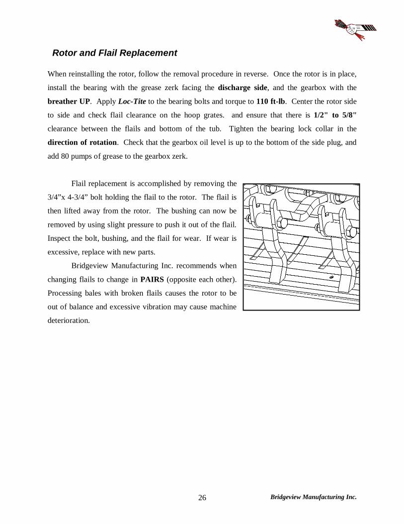
Rotor and Flail Replacement When reinstalling the rotor, follow the removal procedure in reverse. Once the rotor is in place,
install the bearing with the grease zerk facing the discharge side, and the gearbox with the
breather UP. Apply Loc-Tite to the bearing bolts and torque to 110 ft-lb. Center the rotor side
to side and check flail clearance on the hoop grates. and ensure that there is 1/2" to 5/8"
clearance between the flails and bottom of the tub. Tighten the bearing lock collar in the
direction of rotation. Check that the gearbox oil level is up to the bottom of the side plug, and
add 80 pumps of grease to the gearbox zerk.
Flail replacement is accomplished by removing the
3/4”x 4-3/4” bolt holding the flail to the rotor. The flail is
then lifted away from the rotor. The bushing can now be
removed by using slight pressure to push it out of the flail.
Inspect the bolt, bushing, and the flail for wear. If wear is
excessive, replace with new parts.
Bridgeview Manufacturing Inc. recommends when
changing flails to change in PAIRS (opposite each other).
Processing bales with broken flails causes the rotor to be
out of balance and excessive vibration may cause machine
deterioration.

Bridgeview Manufacturing Inc. 27
Transportation The Bale King 5100 can be safely towed on public roads, provided the following precautions are
met:
Tow vehicle and hitch must be rated at least 5300 lb gross, and 1600 lb tongue.
NEVER exceed 40 km/h (25 mph).
ALWAYS ensure that the safety chain is properly installed
Tow vehicle must have a 7 pin round trailer plug (or adaptor)
Plug in lights and check for proper function (flashing amber lights, red tail lights)
Ensure that the supplied SMV (Slow Moving Vehicle) sign is clearly visible from the rear
Lift the forks all the way up and install the safety locks
If possible, the deflector should be in the folded position
Ensure that the deflector safety lock is installed
Ensure that the PTO and hydraulic hoses are properly secured
NOTE: With the deflector folded and no grain tank, the overall width of the processor is 8'-6".
Check with local authorities regarding transport on public roads. Follow all applicable laws
and regulations.
Bridgeview Manufacturing Inc. 28
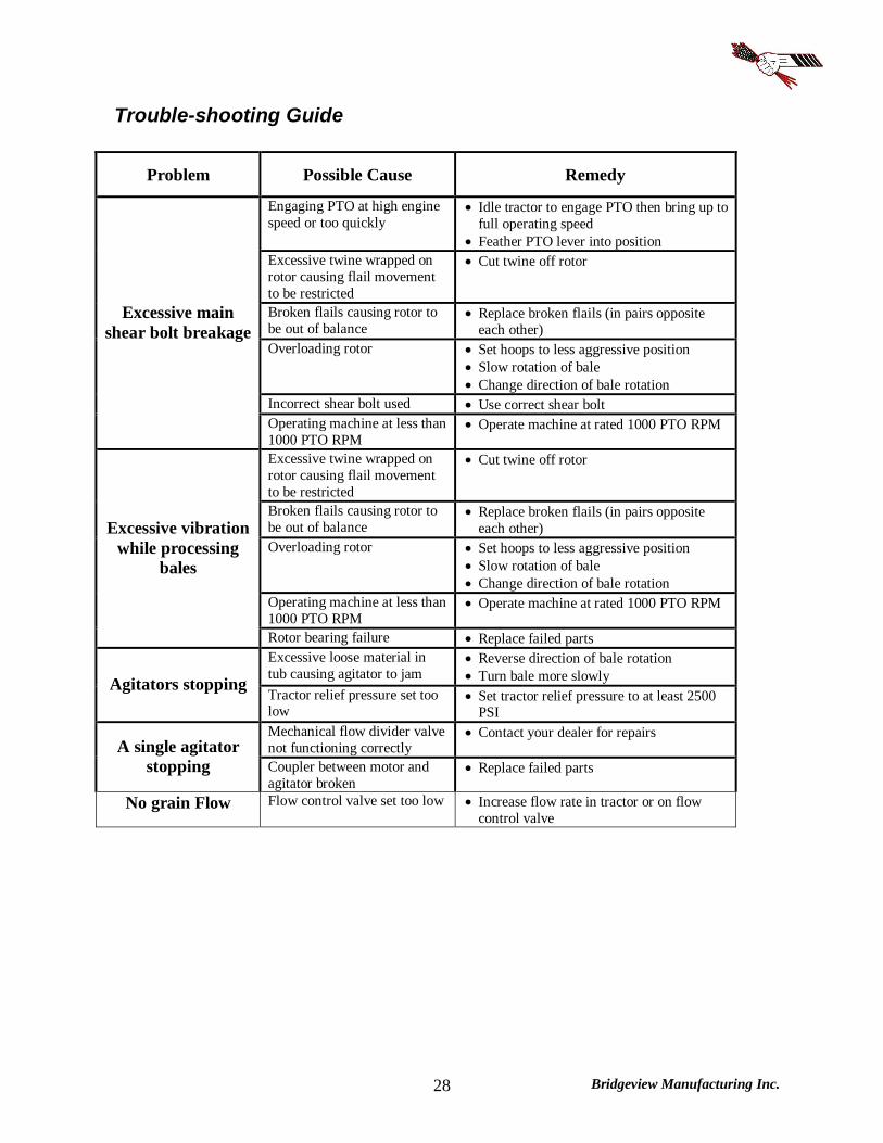
Trouble-shooting Guide
Problem Possible Cause Remedy
Engaging PTO at high engine speed or too quickly
Idle tractor to engage PTO then bring up to full operating speed
Feather PTO lever into position Excessive twine wrapped on rotor causing flail movement to be restricted
Cut twine off rotor
Broken flails causing rotor to be out of balance
Replace broken flails (in pairs opposite each other)
Overloading rotor Set hoops to less aggressive position Slow rotation of bale Change direction of bale rotation
Incorrect shear bolt used Use correct shear bolt
Excessive main shear bolt breakage
Operating machine at less than 1000 PTO RPM
Operate machine at rated 1000 PTO RPM
Excessive twine wrapped on rotor causing flail movement to be restricted
Cut twine off rotor
Broken flails causing rotor to be out of balance
Replace broken flails (in pairs opposite each other)
Overloading rotor Set hoops to less aggressive position Slow rotation of bale Change direction of bale rotation
Operating machine at less than 1000 PTO RPM
Operate machine at rated 1000 PTO RPM
Excessive vibration while processing
bales
Rotor bearing failure Replace failed parts Excessive loose material in tub causing agitator to jam
Reverse direction of bale rotation Turn bale more slowly Agitators stopping
Tractor relief pressure set too low
Set tractor relief pressure to at least 2500 PSI
Mechanical flow divider valve not functioning correctly
Contact your dealer for repairs A single agitator
stopping Coupler between motor and agitator broken
Replace failed parts
No grain Flow Flow control valve set too low Increase flow rate in tractor or on flow control valve

Bridgeview Manufacturing Inc. 29
Features and Specifications Dimensions: 5100 5100TR Overall Weight 4400 lb 5240 lb Drawbar Weight 1250 lb 1600 lb Overall Height 105 in. 105 in. Overall Length (Forks Up) 187 in. 187 in. Overall Length (Forks Down) 217 in. 217 in. Overall Width (Deflector Folded) 102 in. 125 in. Overall Width (Deflector Up) 112 in. 125 in. Overall Width (Deflector Down) 135 in. 145 in. Tread Width (on centers) 78 in. 86 in. Grain Tank Capacity 40 bushels Tub Opening 80 x 91 in. Rotor Extended Tip Diameter 27 in. Discharge Opening 12 x 80 in. Heavy Duty Reinforced Frame and Axle Assembly: Main Frame 4 x 6 in. Tubing Frame Width 52 in. Heavy Duty Square Jack Mounted on Frame Heavy Duty Bale Fork Frame 3 x 6 in. Tubing Adjustable Bale Fork Width (on centers) 48 in. or 40.5 in. Adjustable Hitch Height 4 settings at 1.5 in. intervals Spring Lock Lever on Grate and Fine Chop Adjusters Dual Hydraulic Lift Cylinders 3” x 18” x 1-1/2" Rod Single Hydraulic Deflector Cylinder 1-1/2" x 6" x 3/4" Rod Tire Size 16L x 16.1 6 Ply Tire Inflation 24 psi Wheel Nut Torque 125 ft-lb Minimum Horse Power Requirements 75 HP Required Number of Hydraulic Remotes 2 or 3 (5100) 2, 3 or 4 (5100TR) Rated PTO RPM 1000 RPM Flail Tip Speed at 1000 RPM 7000 FPM Number of Flails 28 Flail Size 3/4 x 1-½ x 7 in. Oil Impregnated Bushing in Flails Rotor Shaft 1-15/16” Bearing Agitator Shaft 1-3/4” Bearings Disc Type Twine Guard PTO Shaft Weasler: Cat. 6 80 deg. C.V. Shear Bolt 3/8 x 2” Gr. 5 Gearbox Oil GL5 80W90 Gearbox Oil Capacity 500 mL
Bridgeview Manufacturing Inc. 30
PARTS MANUAL
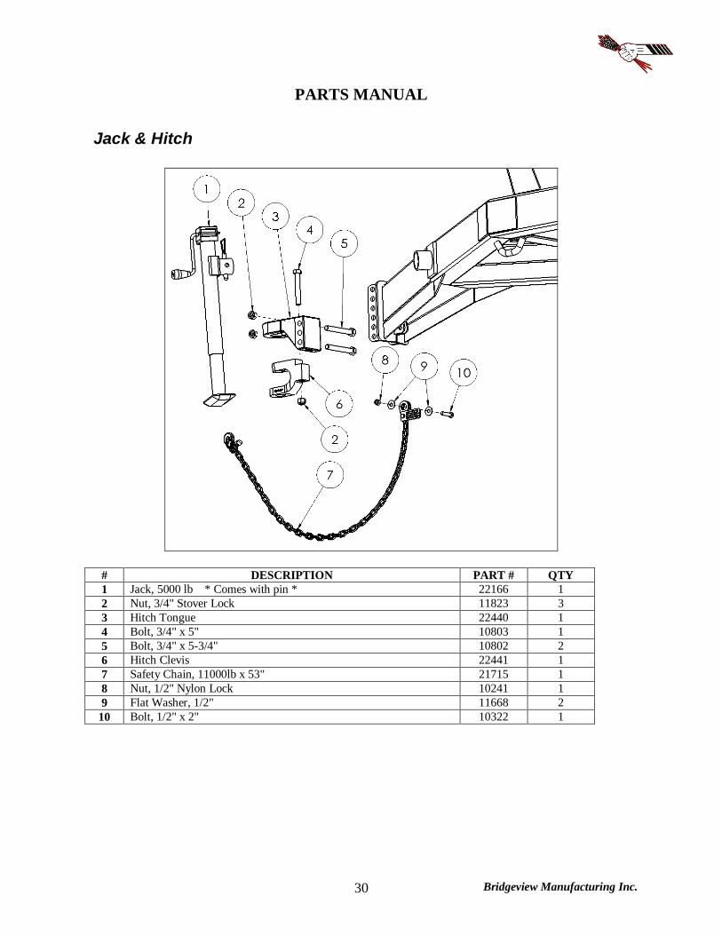
Jack & Hitch
# DESCRIPTION PART # QTY 1 Jack, 5000 lb * Comes with pin * 22166 1 2 Nut, 3/4" Stover Lock 11823 3 3 Hitch Tongue 22440 1 4 Bolt, 3/4" x 5" 10803 1 5 Bolt, 3/4" x 5-3/4" 10802 2 6 Hitch Clevis 22441 1 7 Safety Chain, 11000lb x 53" 21715 1 8 Nut, 1/2" Nylon Lock 10241 1 9 Flat Washer, 1/2" 11668 2
10 Bolt, 1/2" x 2" 10322 1
Bridgeview Manufacturing Inc. 31
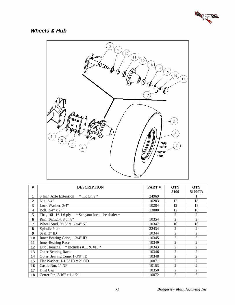
Wheels & Hub
# DESCRIPTION PART # QTY 5100
QTY 5100TR
1 8 Inch Axle Extension * TR Only * 24969 1 2 Nut, 3/4" 10283 12 18 3 Lock Washer, 3/4" 10284 12 18 4 Bolt, 3/4" x 2" 13800 12 18 5 Tire, 16L-16.1 6 ply * See your local tire dealer * - 2 2 6 Rim, 16.1x14, 8 on 8" 10354 2 2 7 Wheel Stud, 9/16" x 1-3/4" NF 10347 16 16 8 Spindle Plate 22434 2 2 9 Seal, 2" ID 10344 2 2
10 Inner Bearing Cone, 1-3/4" ID 10345 2 2 11 Inner Bearing Race 10349 2 2 12 Hub Housing * Includes #11 & #13 * 10343 2 2 13 Outer Bearing Race 10346 2 2 14 Outer Bearing Cone, 1-3/8" ID 10348 2 2 15 Flat Washer, 1-1/6" ID x 2" OD 10071 2 2 16 Castle Nut, 1" NF 10153 2 2 17 Dust Cap 10350 2 2 18 Cotter Pin, 3/16" x 1-1/2" 10072 2 2
Bridgeview Manufacturing Inc. 32
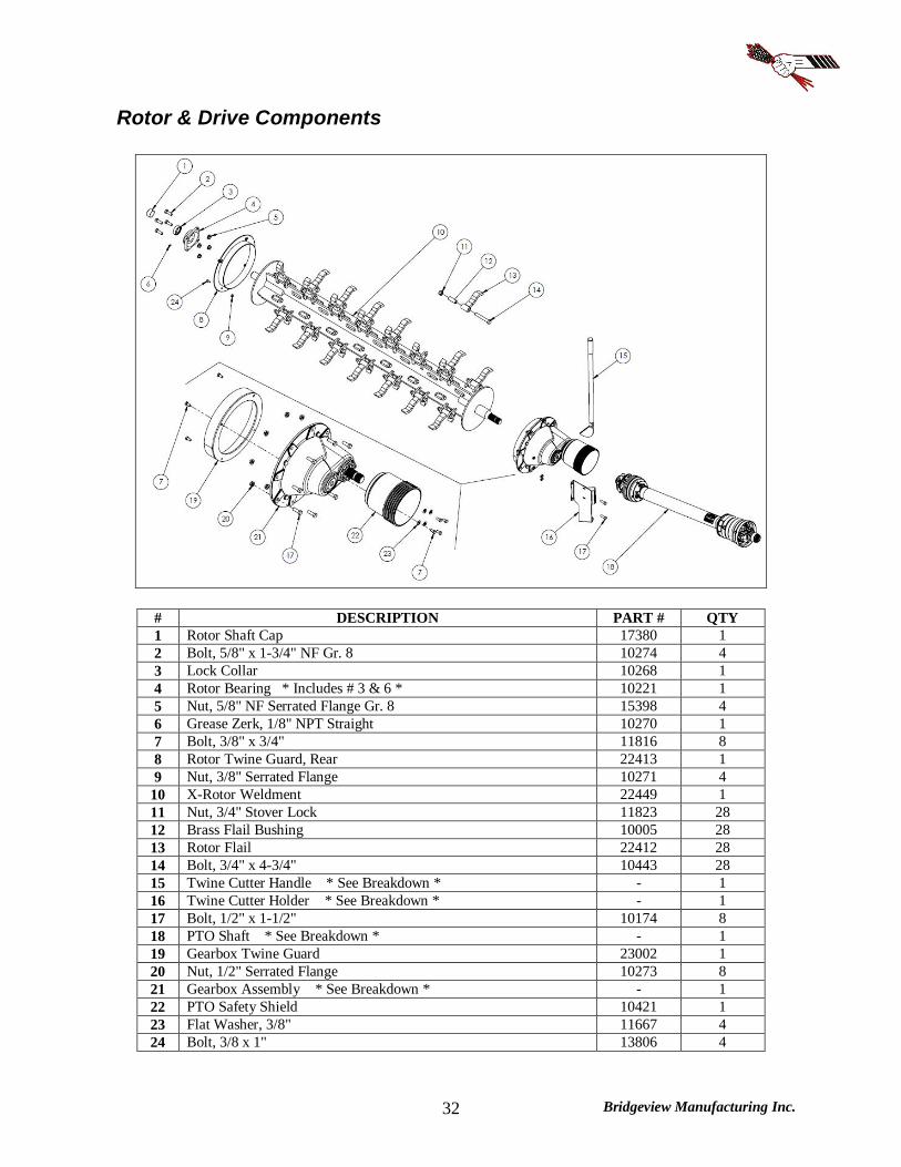
Rotor & Drive Components
# DESCRIPTION PART # QTY 1 Rotor Shaft Cap 17380 1 2 Bolt, 5/8" x 1-3/4" NF Gr. 8 10274 4 3 Lock Collar 10268 1 4 Rotor Bearing * Includes # 3 & 6 * 10221 1 5 Nut, 5/8" NF Serrated Flange Gr. 8 15398 4 6 Grease Zerk, 1/8" NPT Straight 10270 1 7 Bolt, 3/8" x 3/4" 11816 8 8 Rotor Twine Guard, Rear 22413 1 9 Nut, 3/8" Serrated Flange 10271 4
10 X-Rotor Weldment 22449 1 11 Nut, 3/4" Stover Lock 11823 28 12 Brass Flail Bushing 10005 28 13 Rotor Flail 22412 28 14 Bolt, 3/4" x 4-3/4" 10443 28 15 Twine Cutter Handle * See Breakdown * - 1 16 Twine Cutter Holder * See Breakdown * - 1 17 Bolt, 1/2" x 1-1/2" 10174 8 18 PTO Shaft * See Breakdown * - 1 19 Gearbox Twine Guard 23002 1 20 Nut, 1/2" Serrated Flange 10273 8 21 Gearbox Assembly * See Breakdown * - 1 22 PTO Safety Shield 10421 1 23 Flat Washer, 3/8" 11667 4 24 Bolt, 3/8 x 1" 13806 4
Bridgeview Manufacturing Inc. 33
Gearbox
Bridgeview Manufacturing Inc. 34
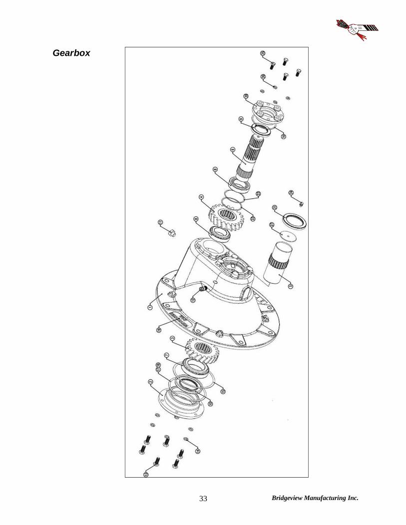
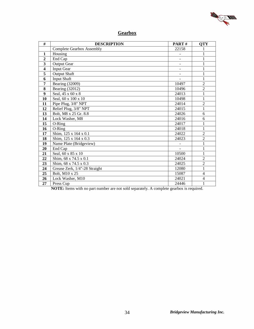
Gearbox
# DESCRIPTION PART # QTY Complete Gearbox Assembly 22158 1 1 Housing - 1 2 End Cap - 1 3 Output Gear - 1 4 Input Gear - 1 5 Output Shaft - 1 6 Input Shaft - 1 7 Bearing (32009) 10497 2 8 Bearing (32012) 10496 2 9 Seal, 45 x 60 x 8 24013 1
10 Seal, 60 x 100 x 10 10498 1 11 Pipe Plug, 3/8" NPT 24014 2 12 Relief Plug, 3/8" NPT 24015 1 13 Bolt, M8 x 25 Gr. 8.8 24026 6 14 Lock Washer, M8 24016 6 15 O-Ring 24017 1 16 O-Ring 24018 1 17 Shim, 125 x 164 x 0.1 24022 2 18 Shim, 125 x 164 x 0.3 24023 2 19 Name Plate (Bridgeview) - 1 20 End Cap - 1 21 Seal, 60 x 85 x 10 10500 1 22 Shim, 68 x 74.5 x 0.1 24024 2 23 Shim, 68 x 74.5 x 0.3 24025 2 24 Grease Zerk, 1/4"-28 Straight 12080 1 25 Bolt, M10 x 25 15087 4 26 Lock Washer, M10 24021 4 27 Press Cup 24446 1
NOTE: Items with no part number are not sold separately. A complete gearbox is required.

Bridgeview Manufacturing Inc. 35
PTO Shaft
# DESCRIPTION PART # QTY Complete PTO Shaft Assembly (1-3/8") 20546 1
1a 1b
Safety Slide Lock Repair Kit (1-3/8"-21 Spline) Safety Slide Lock Repair Kit (1-3/4"-20 Spline)
17567 24981
(1) (1)
2 WWCV Auto-Lok Yoke Assembly (1-3/8"-21 Spline) 20549 (1) 3 WWCV Auto-Lok Yoke Assembly (1-3/4"-20 Spline) 20556 (1) 4 CV Cross and Bearing Kit (Equal Length) 20550 2 5 CV Center Housing 20551 1 6 Yoke & Shaft Assembly Tractor Side 20552 1 7 Guard Repair Kit Tractor Side 20553 1 8 Guard Assembly Tractor Side 17583 1 9 Guard Assembly Implement Side 17585 1
10 Guard Repair Kit Implement Side 17572 1 11 Yoke & Tube Assembly Implement Side 17584 1 12 U-joint Cross & Bearing Kit 17573 1 13 Shear Assembly * Does not come with bolts 14 or 16 * 17581 1 14 Shear Bolt, 3/8" x 2" 11817 1 15 Nut, 3/8" Stover Lock 17586 1 16 Nut, 5/8" Stover Lock 24982 2 17 Bolt, 5/8" x 3-1/2" 24983 2
NOTE: Ensure that the PTO shaft on the machine is correct to the drawings below. Equal length CV cross (4.19") with bearing cup diameter 1.38". If the damaged PTO has different dimensions, consult the Bridgeview Manufacturing website.

Bridgeview Manufacturing Inc. 36
Twine Cutter
# DESCRIPTION PART # QTY 1 Twine Cutter Handle Kit - 1 2 Twine Cutter Holder Kit 21549 1 3 Rubber Handle Cap 17587 1 4 Twine Cutter Handle 20862 1 5 Bolt, 1/4" x 3/4" Truss Head 17638 4 6 Nut, 1/4" Serrated Flange 11812 4 7 Twine Cutter Blade 17438 1 8 Twine Cutter Holder Inside Bracket 17690 1 9 Twine Cutter Holder Outside Bracket 17691 1
10 Flat Washer, 1/4" 11666 2
Bridgeview Manufacturing Inc. 37
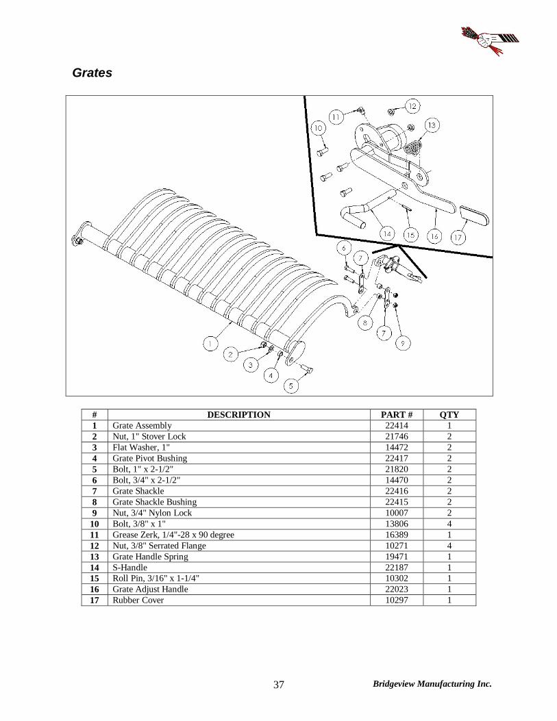
Grates
# DESCRIPTION PART # QTY 1 Grate Assembly 22414 1 2 Nut, 1" Stover Lock 21746 2 3 Flat Washer, 1" 14472 2 4 Grate Pivot Bushing 22417 2 5 Bolt, 1" x 2-1/2" 21820 2 6 Bolt, 3/4" x 2-1/2" 14470 2 7 Grate Shackle 22416 2 8 Grate Shackle Bushing 22415 2 9 Nut, 3/4" Nylon Lock 10007 2
10 Bolt, 3/8" x 1" 13806 4 11 Grease Zerk, 1/4"-28 x 90 degree 16389 1 12 Nut, 3/8" Serrated Flange 10271 4 13 Grate Handle Spring 19471 1 14 S-Handle 22187 1 15 Roll Pin, 3/16" x 1-1/4" 10302 1 16 Grate Adjust Handle 22023 1 17 Rubber Cover 10297 1

Bridgeview Manufacturing Inc. 38
Agitators
# DESCRIPTION PART # QTY 5100
QTY 5100TR
1 Agitator Shaft Cap 17381 2 2 2 Bolt, 1/2" x 1-1/2" 10174 8 8 3 Lock Collar 10040 2 2 4a Grease Zerk, 1/8" NPT Straight 10270 2 1 4b Grease Zerk, 1/8" NPT 45 degree * TR Only * 15640 1 5 Agitator Bearing * Includes # 3 & 4a * 10038 2 2 6 Nut, 1/2" Serrated Flange 10273 8 8 7 Agitator 22418 2 2 8 Nut, 3/8" Serrated Flange 10271 16 16 9 Agitator Twine Guard 22419 4 4 10 Bolt, 3/8" x 3/4" 11816 16 16 11 Agitator Insert 22084 2 2 12 Agitator Motor, 8" Long (S/N BK6416 & up)
* Seal Kit Agitator Motor, 6-1/2" Long (S/N BK6415 & below) # * Seal Kit
25872 25891 21720 22820
2 2
13 Lock Washer, 1/2" 14447 8 8 14 Socket Head Bolt, 1/2" x 3" (S/N BK6416 & up)
Socket Head Bolt, 1/2" x 2-1/2" (S/N BK6415 & below) 25952 16863
8 8
NOTE: Check the serial number (S/N) of your machine before ordering.
Bridgeview Manufacturing Inc. 39
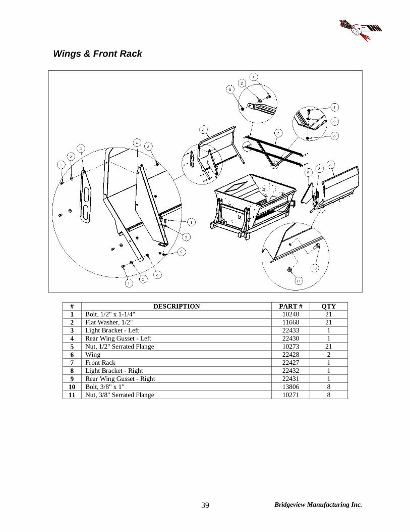
Wings & Front Rack
# DESCRIPTION PART # QTY 1 Bolt, 1/2" x 1-1/4" 10240 21 2 Flat Washer, 1/2" 11668 21 3 Light Bracket - Left 22433 1 4 Rear Wing Gusset - Left 22430 1 5 Nut, 1/2" Serrated Flange 10273 21 6 Wing 22428 2 7 Front Rack 22427 1 8 Light Bracket - Right 22432 1 9 Rear Wing Gusset - Right 22431 1
10 Bolt, 3/8" x 1" 13806 8 11 Nut, 3/8" Serrated Flange 10271 8
Bridgeview Manufacturing Inc. 40
Rear Forks
Bridgeview Manufacturing Inc. 41
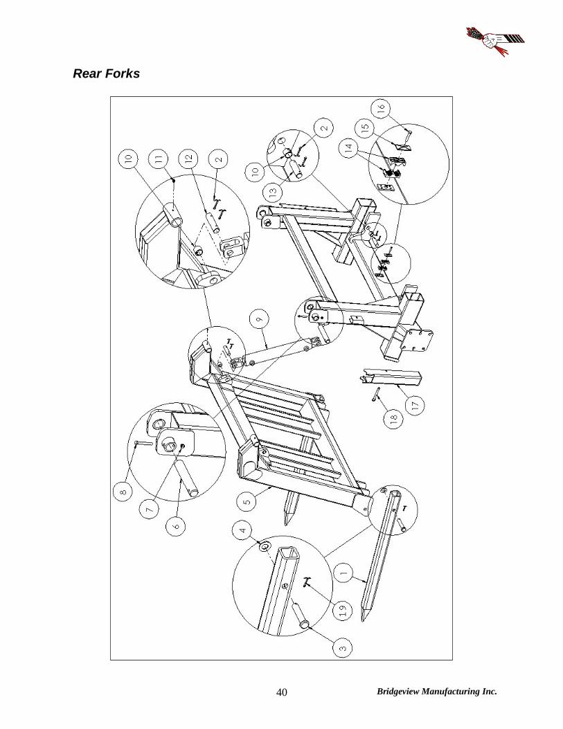
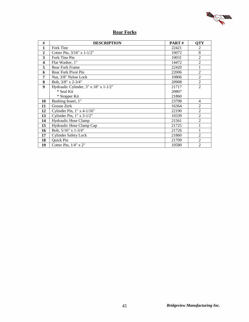
Rear Forks
# DESCRIPTION PART # QTY 1 Fork Tine 22421 2 2 Cotter Pin, 3/16" x 1-1/2" 10072 8 3 Fork Tine Pin 10031 2 4 Flat Washer, 1" 14472 2 5 Rear Fork Frame 22420 1 6 Rear Fork Pivot Pin 22006 2 7 Nut, 3/8" Nylon Lock 10806 2 8 Bolt, 3/8" x 2-3/4" 20908 2 9 Hydraulic Cylinder, 3" x 18" x 1-1/2"
* Seal Kit * Stopper Kit
21717 20807 21860
2
10 Bushing Insert, 1" 23708 4 11 Grease Zerk 16364 2 12 Cylinder Pin, 1" x 4-1/16" 22190 2 13 Cylinder Pin, 1" x 3-1/2" 10339 2 14 Hydraulic Hose Clamp 21561 2 15 Hydraulic Hose Clamp Cap 21725 1 16 Bolt, 5/16" x 1-3/4" 21726 1 17 Cylinder Safety Lock 21860 2 18 Quick Pin 21709 2 19 Cotter Pin, 1/4" x 2" 10580 2

Bridgeview Manufacturing Inc. 42
Deflector & Hose Cover

Bridgeview Manufacturing Inc. 43
Deflector & Hose Cover
# DESCRIPTION PART # QTY 1 Bolt, 3/8" x 1" 13806 8 2 Deflector Rubber Channel 22423 1 3 Deflector Rubber 10477 1 4 Nut, 3/8" Nylon Lock 10806 8 5 Carriage Bolt, 3/8" x 3/4" 14072 7 6 Deflector Flipper Pin 24464 1 7 Nut, 3/8" Serrated Flange 10271 20 8 Compression Spring 24461 1 9 Roll Pin, 3/16" x 1-1/4" 10302 1
10 Deflector Pivot 22426 2 11 Inner Deflector 22425 1 12 Bolt, 3/8" x 3/4" 11816 13 13 Hose Cover 22436 1 14 Cotter Pin, 3/16" x 1-1/4" 11669 4 15 Cylinder Pin, 3/4" x 3" Usable 22007 1 16 Hydraulic Cylinder, 1-1/2" x 6" x 3/4"
* Seal Kit 21711 23738
1
17 Cylinder Pin, 3/4" x 3" Usable 22007 1 18 Deflector Rubber Flipper 24463 1 19 Outer Deflector - Flip-Style
Outer Deflector - Rigid # 24462 25078
1
20 Nut, 1/2" Serrated Flange 10273 12 21 Bolt, 1/2" x 1" 10824 8 22 Bolt, 1/2" x 2" 10322 1 23 Deflector Lock 22422 1 24 Pin Stud 13231 1 25 Lynch Pin 13233 1 26 Hose Cover Front @ 22945 1 27 Flat Washer, 3/8" 11667 10
# NOTE: For machines with a rigid rubber deflector, order kit #25078 to upgrade to a flip-style deflector. @ NOTE: For machines without a front cover, order kit #23220
Bridgeview Manufacturing Inc. 44
Front Tub Components
Bridgeview Manufacturing Inc. 45
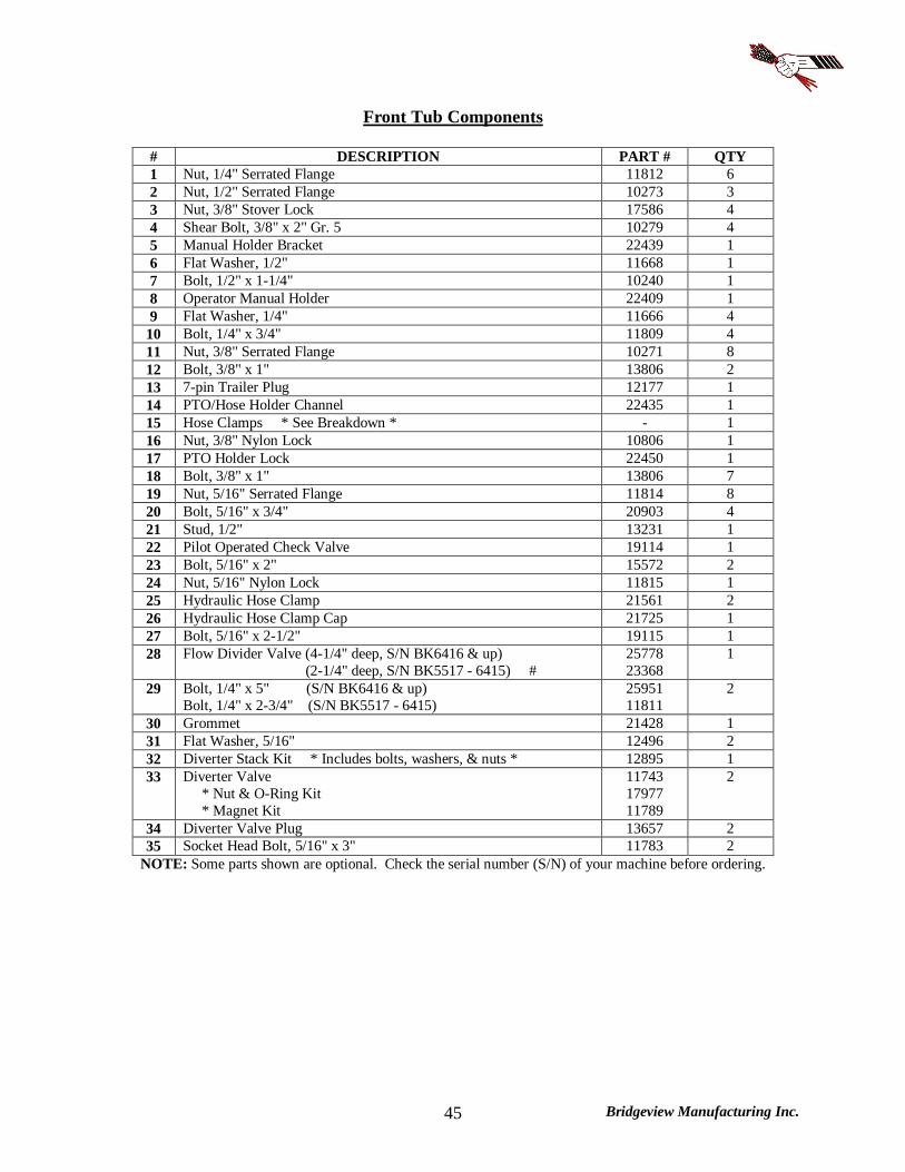
Front Tub Components
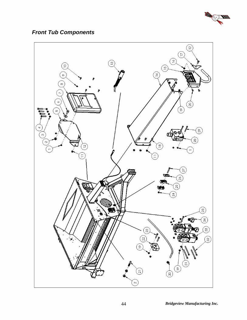
# DESCRIPTION PART # QTY 1 Nut, 1/4" Serrated Flange 11812 6 2 Nut, 1/2" Serrated Flange 10273 3 3 Nut, 3/8" Stover Lock 17586 4 4 Shear Bolt, 3/8" x 2" Gr. 5 10279 4 5 Manual Holder Bracket 22439 1 6 Flat Washer, 1/2" 11668 1 7 Bolt, 1/2" x 1-1/4" 10240 1 8 Operator Manual Holder 22409 1 9 Flat Washer, 1/4" 11666 4
10 Bolt, 1/4" x 3/4" 11809 4 11 Nut, 3/8" Serrated Flange 10271 8 12 Bolt, 3/8" x 1" 13806 2 13 7-pin Trailer Plug 12177 1 14 PTO/Hose Holder Channel 22435 1 15 Hose Clamps * See Breakdown * - 1 16 Nut, 3/8" Nylon Lock 10806 1 17 PTO Holder Lock 22450 1 18 Bolt, 3/8" x 1" 13806 7 19 Nut, 5/16" Serrated Flange 11814 8 20 Bolt, 5/16" x 3/4" 20903 4 21 Stud, 1/2" 13231 1 22 Pilot Operated Check Valve 19114 1 23 Bolt, 5/16" x 2" 15572 2 24 Nut, 5/16" Nylon Lock 11815 1 25 Hydraulic Hose Clamp 21561 2 26 Hydraulic Hose Clamp Cap 21725 1 27 Bolt, 5/16" x 2-1/2" 19115 1 28 Flow Divider Valve (4-1/4" deep, S/N BK6416 & up)
(2-1/4" deep, S/N BK5517 - 6415) # 25778 23368
1
29 Bolt, 1/4" x 5" (S/N BK6416 & up) Bolt, 1/4" x 2-3/4" (S/N BK5517 - 6415)
25951 11811
2
30 Grommet 21428 1 31 Flat Washer, 5/16" 12496 2 32 Diverter Stack Kit * Includes bolts, washers, & nuts * 12895 1 33 Diverter Valve
* Nut & O-Ring Kit * Magnet Kit
11743 17977 11789
2
34 Diverter Valve Plug 13657 2 35 Socket Head Bolt, 5/16" x 3" 11783 2
NOTE: Some parts shown are optional. Check the serial number (S/N) of your machine before ordering.

Bridgeview Manufacturing Inc. 46
PTO Holder
# DESCRIPTION PART # 1 PTO/Hose Holder Front Plate 22838 2 Hydraulic Hose Clamp, 1/2" 21561 3 Hydraulic Hose Clamp, 3/8" 22180 4 Hydraulic Hose Clamp, 1/4" 22181 5 Hydraulic Hose Clamp Cap, Large 21725 6 Hydraulic Hose Clamp Cap, Small 22182 7 Bolt, 5/16" x 3-1/2" 13765 8 Bolt, 5/16" x 3" 22844 9 Bolt, 5/16" x 1-3/4" 21726
10 Bolt, 5/16" x 1-3/8" 22183 11 Wiring Clamp 13629
NOTE: Quantities are as required
Bridgeview Manufacturing Inc. 47
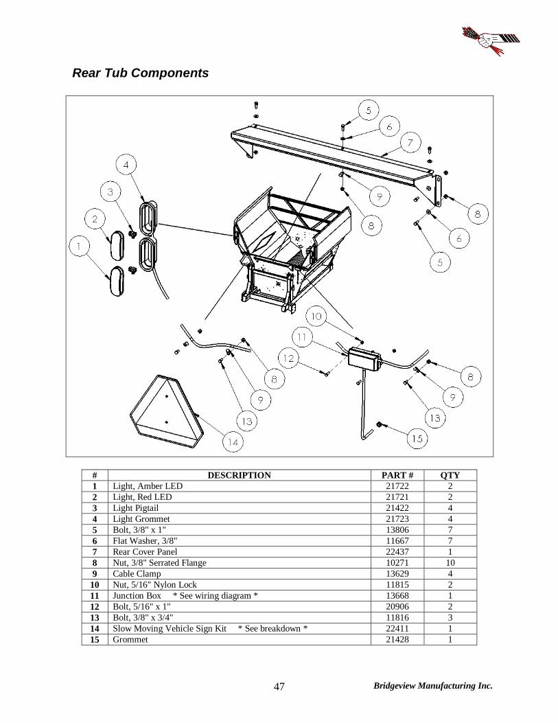
Rear Tub Components
# DESCRIPTION PART # QTY 1 Light, Amber LED 21722 2 2 Light, Red LED 21721 2 3 Light Pigtail 21422 4 4 Light Grommet 21723 4 5 Bolt, 3/8" x 1" 13806 7 6 Flat Washer, 3/8" 11667 7 7 Rear Cover Panel 22437 1 8 Nut, 3/8" Serrated Flange 10271 10 9 Cable Clamp 13629 4
10 Nut, 5/16" Nylon Lock 11815 2 11 Junction Box * See wiring diagram * 13668 1 12 Bolt, 5/16" x 1" 20906 2 13 Bolt, 3/8" x 3/4" 11816 3 14 Slow Moving Vehicle Sign Kit * See breakdown * 22411 1 15 Grommet 21428 1
Bridgeview Manufacturing Inc. 48
Slow Moving Vehicle (SMV) Sign Kit
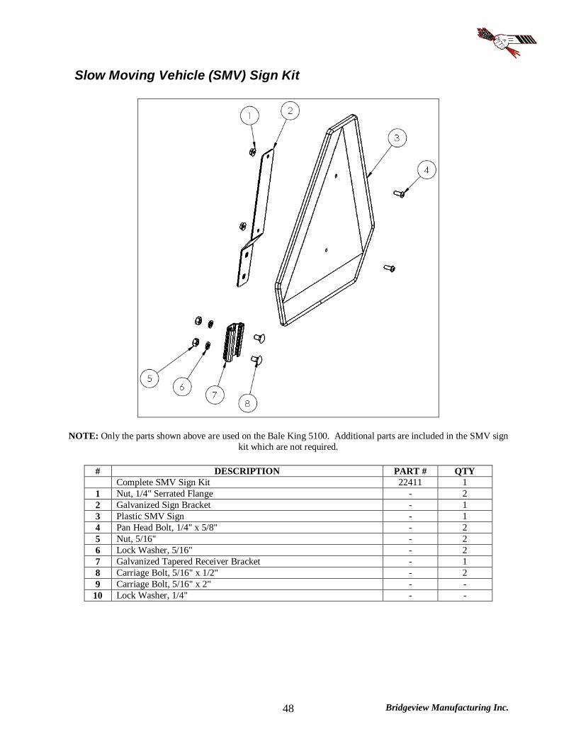
NOTE: Only the parts shown above are used on the Bale King 5100. Additional parts are included in the SMV sign kit which are not required.
# DESCRIPTION PART # QTY Complete SMV Sign Kit 22411 1 1 Nut, 1/4" Serrated Flange - 2 2 Galvanized Sign Bracket - 1 3 Plastic SMV Sign - 1 4 Pan Head Bolt, 1/4" x 5/8" - 2 5 Nut, 5/16" - 2 6 Lock Washer, 5/16" - 2 7 Galvanized Tapered Receiver Bracket - 1 8 Carriage Bolt, 5/16" x 1/2" - 2 9 Carriage Bolt, 5/16" x 2" - -
10 Lock Washer, 1/4" - -
Bridgeview Manufacturing Inc. 49
Decals
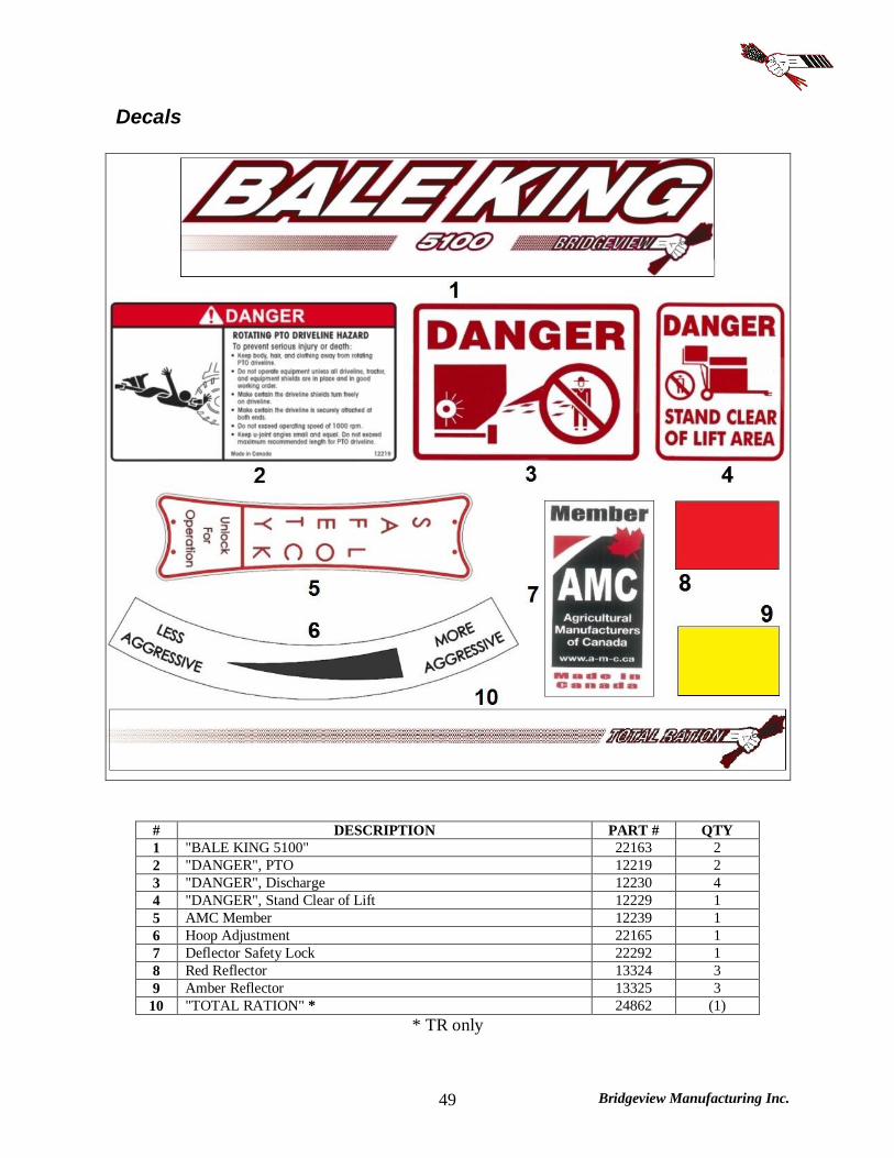
# DESCRIPTION PART # QTY 1 "BALE KING 5100" 22163 2 2 "DANGER", PTO 12219 2 3 "DANGER", Discharge 12230 4 4 "DANGER", Stand Clear of Lift 12229 1 5 AMC Member 12239 1 6 Hoop Adjustment 22165 1 7 Deflector Safety Lock 22292 1 8 Red Reflector 13324 3 9 Amber Reflector 13325 3
10 "TOTAL RATION" * 24862 (1) * TR only

Bridgeview Manufacturing Inc. 50
Fine Chop

Bridgeview Manufacturing Inc. 51
Fine Chop
# DESCRIPTION PART # QTY 1 Fin Bolt, 3/8" x 3/4" 10807 8 2 Nut, 3/8" Serrated Flange 10271 8 3 Fine Chop Cover Plate 22438 1 Fine Chop Kit * Optional * 22139 1 4 Bolt, 3/8" x 1" 13806 6 5 Fine Chop Pivot Front 22443 1 6 Nut, 3/8" Serrated Flange 10271 6 7 Rubber Handle 10297 1 8 Fine Chop Handle 22446 1 9 Bolt, 1/2" x 2-1/2" 10804 1
10 Fine Chop Handle Mount 22445 1 11 Flat Washer, 1/2" 11668 1 12 Compression Spring 21713 1 13 Nut, 1/2" Nylon Lock 10241 1 14 Nut, 1/4" Serrated Flange 11812 26 15 Fine Chop Blade 10404 13 16 Bolt, 1/4" x 3/4" 11809 26 17 Fine Chop Bar
*NOTE: On newer kits, handle mount (#10) is part of this piece 22442 1
18 Fine Chop Pivot Rear 22444 1 19 Split Collar 12792 1
Fine Chop Adaptor Kit * TR Only * 22042 1
20 Carriage Bolt, 3/8" x 1" 15718 2 21 Fine Chop Adaptor Pivot 25051 1 22 Nut, 3/8" Serrated Flange 10271 2 23 Grease Zerk 16374 1 24 Bolt, 1/2" x 1-1/4" 10240 2 25 Fine Chop Adaptor Linkage 25048 1 26 Nut, 1/2" Nylon Lock 10241 2
Bridgeview Manufacturing Inc. 52
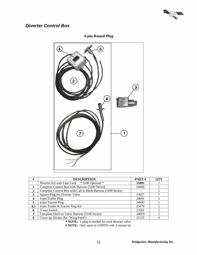
Diverter Control Box
4-pin Round Plug
# DESCRIPTION PART # QTY Diverter Kit with Line Lock * 5100 Optional * 25091 1 1 Complete Control Box with Harness (5100 Series) 24466 1 2 Complete Control Box with Cab to Hitch Harness (5100 Series) - 1 3 Square Plug for Diverter Valve 13657 * 4 4-pin Trailer Plug 24691 1 5 4-pin Tractor Plug 24690 1
4,5 4-pin Trailer & Tractor Plug Kit 25079 1 6 3-way Switch 13561 1 7 Complete Hitch to Valve Harness (5100 Series) 24693 1 8 Cover-up Sticker (for "Wing/Feed") 25125 #
* NOTE: 1 plug is needed for each diverter valve. # NOTE: Only used on 5100TR with 3 remote kit.
Bridgeview Manufacturing Inc. 53
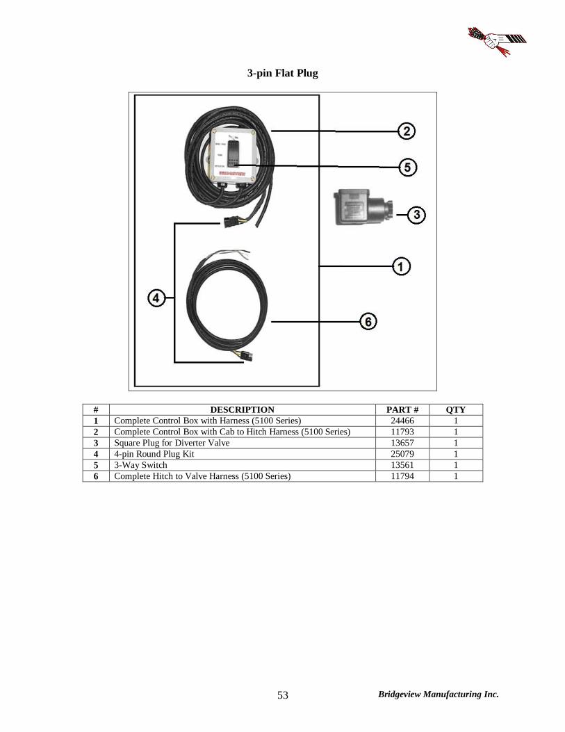
3-pin Flat Plug
# DESCRIPTION PART # QTY 1 Complete Control Box with Harness (5100 Series) 24466 1 2 Complete Control Box with Cab to Hitch Harness (5100 Series) 11793 1 3 Square Plug for Diverter Valve 13657 1 4 4-pin Round Plug Kit 25079 1 5 3-Way Switch 13561 1 6 Complete Hitch to Valve Harness (5100 Series) 11794 1
Bridgeview Manufacturing Inc. 54
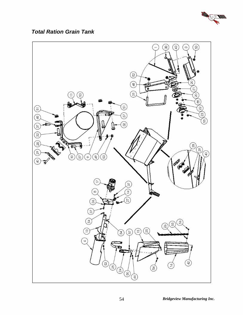
Total Ration Grain Tank
Bridgeview Manufacturing Inc. 55

Bridgeview Manufacturing Inc. 56
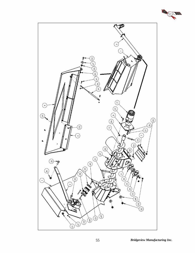
Total Ration Grain Tank (S/N 25580 & up) NOTE: For tanks with S/N below 25579, contact Bridgeview for parts.
# DESCRIPTION PART # QTY Total Ration Grain Tank Kit
2 Remote Kit * CHOOSE ONE * 3 Remote Kit * CHOOSE ONE * 4 Remote Kit * CHOOSE ONE * Fine Chop Adaptor Kit * REQ'D FOR FINE CHOP ONLY*
22040 22045 22044 22043 22042
1 (1) (1) (1)
OPTIONAL 1 Total Ration Grain Tank 25084 1 2 Grain Tank Top Connector 25093 2 3 Grain Tank Cleanout Door 25096 1 4 Grain Tank Lid 25085 1 5 Grain Tank Lid Baffle 25092 3 6 Cross Auger Pipe 25820 1 7 Cross Auger Cleanout Door 25095 1 8 Auger Motor Mount 25826 2 9 Cross Auger Support - Base 25088 1
10 Cross Auger Support - Upper 25089 1 11 Cross Auger Support - Clamp 25094 1 12 Grain Tank Auger 25041 1 13 Cross Auger 25042 1 14 Auger Spout Chain Catch 25097 1 15 Auger Spout - Top 25123 1 16 Auger Spout - Bottom 25124 1 17 Hydraulic Motor
* Seal Kit 25810 25827
2
18 Flow Control Valve 10455 1 19 Gas Shock 16808 1 20 Bearing, 3-Bolt Pressed Flange Housing 10368 4 21 Bearing, 3/4" * Includes # 22 * 10366 2 22 Bearing Lock Collar 10367 2 23 Bearing Cover 25117 1 24 Strap w/ Buckle 25 Strap w/o Buckle 25122 1
26 Chain, 3/16" x 20 links 25121 1 27 Lock Pin, 1/4" x 1-1/4" 13951 1 28 Hydraulic Hose Clamp, 1/2" 21561 6 29 Hydraulic Hose Clamp Cap, Large 21715 3 30 Bushing, 1/2" ID x 1-1/4" OD 10239 2 31 Square U-bolt, 1/2" x 6" x 5-1/2" 25056 2 32 Bolt, 1/2" x 1-1/2" 10174 7 33 Bolt, 1/2" x 1" 10824 2 34 Bolt, 3/8" x 2" 10279 2 35 Bolt, 3/8" x 1-1/2" 11660 1 36 Lock Washer, 3/8" 13971 8 37 Bolt, 3/8" x 1" 13806 26 38 Bolt, 3/8" x 3/4" 11816 8 39 Fin Bolt, 3/8" x 3/4" 10807 9 40 Bolt, 5/16" x 1-3/4" 21726 3 41 Bolt, 5/16" x 1-1/4" 24418 2 42 Bolt, 5/16" x 1" 20906 1 43 Carriage Bolt, 5/16" x 1" 17884 3 44 Carriage Bolt, 5/16" x 3/4" 11662 3 45 Bolt, 1/4" x 2-1/2" 11811 2 46 Truss Head Bolt, 1/4" x 1/2" 22619 2 47 Fender Washer, 1/2" 10238 2 48 Flat Washer, 1/2" 11668 4 49 Flat Washer, 3/8" 11667 8 50 Flat Washer, 1/4" 11666 2 51 Nut, 1/2" Serrated Flange 10273 2 52 Nut, 1/2" Nylon Lock 10241 6 53 Nut, 3/8" Serrated Flange 10271 35 54 Nut, 3/8" Nylon Lock 10806 3 55 Nut, 5/16" Serrated Flange 11814 10 56 Nut, 5/16" Nylon Lock 11815 3 57 Nut, 1/4" Serrated Flange 11813 4
Bridgeview Manufacturing Inc. 57
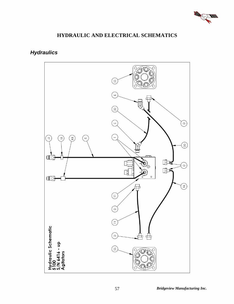
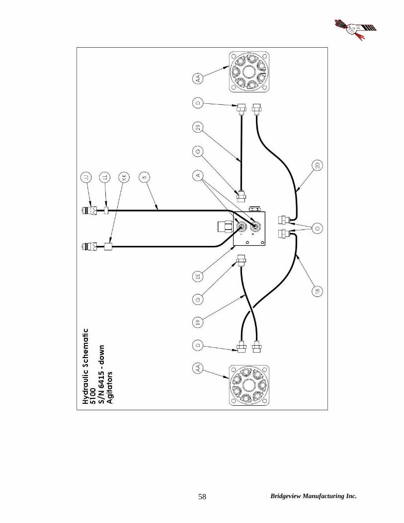
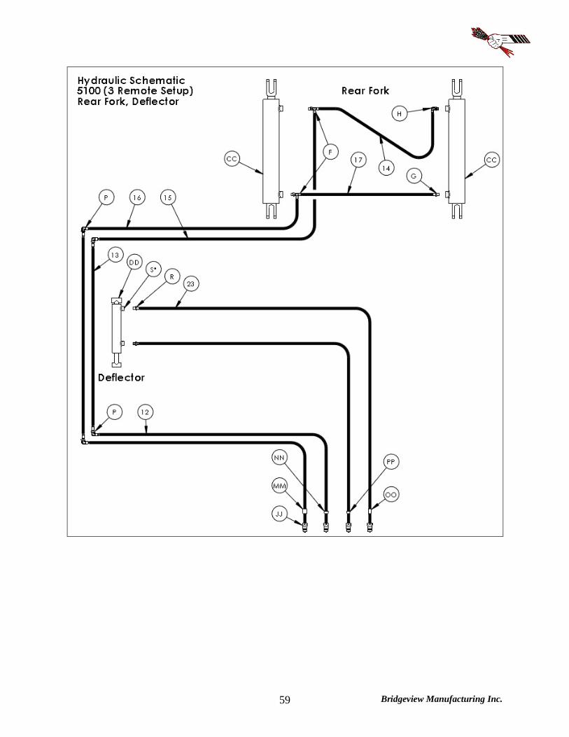
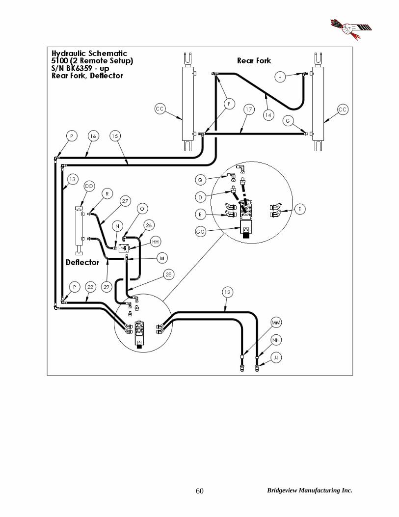
HYDRAULIC AND ELECTRICAL SCHEMATICS
Hydraulics
Bridgeview Manufacturing Inc. 58
Bridgeview Manufacturing Inc. 59
Bridgeview Manufacturing Inc. 60

Bridgeview Manufacturing Inc. 61

Bridgeview Manufacturing Inc. 62

Bridgeview Manufacturing Inc. 63

Bridgeview Manufacturing Inc. 64
Bridgeview Manufacturing Inc. 65
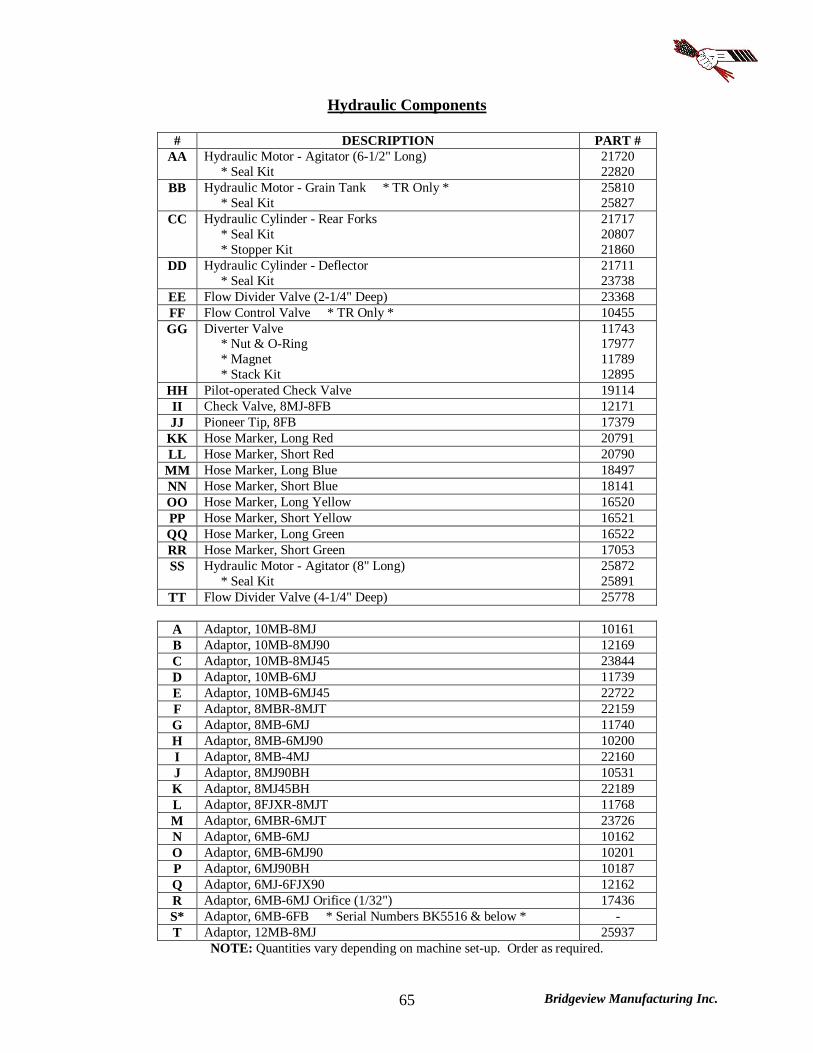
Hydraulic Components
# DESCRIPTION PART # AA Hydraulic Motor - Agitator (6-1/2" Long)
* Seal Kit 21720 22820
BB Hydraulic Motor - Grain Tank * TR Only * * Seal Kit
25810 25827
CC Hydraulic Cylinder - Rear Forks * Seal Kit * Stopper Kit
21717 20807 21860
DD Hydraulic Cylinder - Deflector * Seal Kit
21711 23738
EE Flow Divider Valve (2-1/4" Deep) 23368 FF Flow Control Valve * TR Only * 10455 GG Diverter Valve
* Nut & O-Ring * Magnet * Stack Kit
11743 17977 11789 12895
HH Pilot-operated Check Valve 19114 II Check Valve, 8MJ-8FB 12171 JJ Pioneer Tip, 8FB 17379
KK Hose Marker, Long Red 20791 LL Hose Marker, Short Red 20790
MM Hose Marker, Long Blue 18497 NN Hose Marker, Short Blue 18141 OO Hose Marker, Long Yellow 16520 PP Hose Marker, Short Yellow 16521 QQ Hose Marker, Long Green 16522 RR Hose Marker, Short Green 17053 SS Hydraulic Motor - Agitator (8" Long)
* Seal Kit 25872 25891
TT Flow Divider Valve (4-1/4" Deep) 25778
A Adaptor, 10MB-8MJ 10161 B Adaptor, 10MB-8MJ90 12169 C Adaptor, 10MB-8MJ45 23844 D Adaptor, 10MB-6MJ 11739 E Adaptor, 10MB-6MJ45 22722 F Adaptor, 8MBR-8MJT 22159 G Adaptor, 8MB-6MJ 11740 H Adaptor, 8MB-6MJ90 10200 I Adaptor, 8MB-4MJ 22160 J Adaptor, 8MJ90BH 10531 K Adaptor, 8MJ45BH 22189 L Adaptor, 8FJXR-8MJT 11768 M Adaptor, 6MBR-6MJT 23726 N Adaptor, 6MB-6MJ 10162 O Adaptor, 6MB-6MJ90 10201 P Adaptor, 6MJ90BH 10187 Q Adaptor, 6MJ-6FJX90 12162 R Adaptor, 6MB-6MJ Orifice (1/32") 17436 S* Adaptor, 6MB-6FB * Serial Numbers BK5516 & below * - T Adaptor, 12MB-8MJ 25937
NOTE: Quantities vary depending on machine set-up. Order as required.
Bridgeview Manufacturing Inc. 66
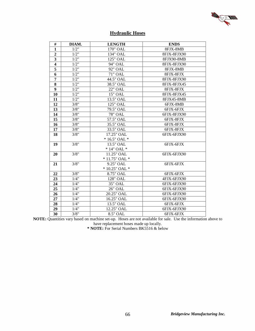
Hydraulic Hoses
# DIAM. LENGTH ENDS 1 1/2" 170" OAL 8FJX-8MB 2 1/2" 134" OAL 8FJX-8FJX90 3 1/2" 125" OAL 8FJX90-8MB 4 1/2" 94" OAL 8FJX-8FJX90 5 1/2" 92" OAL 8FJX-8MB 6 1/2" 71" OAL 8FJX-8FJX 7 1/2" 44.5" OAL 8FJX-8FJX90 8 1/2" 38.5" OAL 8FJX-8FJX45 9 1/2" 22" OAL 8FJX-8FJX 10 1/2" 15" OAL 8FJX-8FJX45 11 1/2" 13.5" OAL 8FJX45-8MB 12 3/8" 125" OAL 6FJX-8MB 13 3/8" 79.5" OAL 6FJX-6FJX 14 3/8" 78" OAL 6FJX-8FJX90 15 3/8" 57.5" OAL 6FJX-8FJX 16 3/8" 35.5" OAL 6FJX-8FJX 17 3/8" 33.5" OAL 6FJX-8FJX 18 3/8" 17.25" OAL
* 16.5" OAL * 6FJX-6FJX90
19 3/8" 13.5" OAL * 14" OAL *
6FJX-6FJX
20 3/8" 11.25" OAL * 11.75" OAL *
6FJX-6FJX90
21 3/8" 9.25" OAL * 10.25" OAL *
6FJX-6FJX
22 3/8" 8.75" OAL 6FJX-6FJX 23 1/4" 128" OAL 4FJX-6FJX90 24 1/4" 35" OAL 6FJX-6FJX90 25 1/4" 26" OAL 6FJX-6FJX90 26 1/4" 20.25" OAL 6FJX-6FJX90 27 1/4" 16.25" OAL 6FJX-6FJX90 28 1/4" 13.5" OAL 6FJX-6FJX 29 1/4" 12.25" OAL 6FJX-6FJX90 30 3/8" 8.5" OAL 6FJX-6FJX
NOTE: Quantities vary based on machine set-up. Hoses are not available for sale. Use the information above to have replacement hoses made up locally.
* NOTE: For Serial Numbers BK5516 & below
Bridgeview Manufacturing Inc. 67
Lights & Electrical
Diverter Controls

Bridgeview Manufacturing Inc. 68
Lights

Bridgeview Manufacturing Inc. 69
Junction Box: S/N BK6359 - up

Bridgeview Manufacturing Inc. 70
Junction Box: S/N BK5426 - 6358

Bridgeview Manufacturing Inc. 71
NOTES
---------------------------------------------------------------------------------------------------------------------------------------------------------------------------------------------------------------------------------------------------------------------------------------------------------------------------------------------------------------------------------------------------------------------------------------------------------------------------------------------------------------------------------------------------------------------------------------------------------------------------------------------------------------------------------------------------------------------------------------------------------------------------------------------------------------------------------------------------------------------------------------------------------------------------------------------------------------------------------------------------------------------------------------------------------------------------------------------------------------------------------------------------------------------------------------------------------------------------------------------------------------------------------------------------------------------------------------------------------------------------------------------------------------------------------------------------------------------------------------------------------------------------------------------------------------------------------------------------------------------------------------------------------------------------------------------------------------------------------------------------------------------------------------------------------------------------------------------------------------------------------------------------------------------------------------------------------------------------------------------------------------------------------------------------------------------------------------------------------------------------------------------------------------------------------------------------------------------------------------------------------------------------------------------------------------------------------------------------------------------------------------------------------------------------------------------------------------------------------------------------------------------------------------------------------------------------------------------------------------------------------------------------------------------------------------------------------------------------------------------------------------------------------------------------------------------------------------------------------------------------------------------------------------------------------------------------------------------------------------------------------------------------------------------------------------------------------------------------------------------------------------------------------------------------------------------------------------------------------------------------------------------------------------------------------------------------------------------------------------------------------------------------------------------------------------------------------------------------------------------------------------------------------------------------------------------------------------------------------------------------------------------------------------------------------------------------------------------------------------------------------------------------------------------------------------------------------------------------------------------------------------------------------------------------------------------------------------------------------------------------------------------------------------------------------------------------------------------------------------------------------------------------------------------------------------------------------------------------------------------------------------------------------------------------------------------------------------------------------------------------------------------------------------------------------------------------------------------------------------------------------------------------------------------------------------------------------------------------------------------------------------------------------------------------------------------------------------------------------------------------------------------------------------------------------------------------------------------------------------------------------------------------------------------------------------------------------------------------------------------