Balancing System Details for Open Pocket Rigid and Hydro ... · ALL WATER BALANCED OPEN POCKET...
17
MSSMA401AE/9909AV (1 of 17) È BALANCING SYSTEM DETAILS FOR ALL WATER BALANCED OPEN POCKET RIGID AND HYDRO-CUSHION WASHER-EXTRACTORS • Basic concept • Balancing System Safety Features for Both Rigid and HYDRO-CUSHION Machines • Monitoring the Balancing System • Balancing System Adjustments and Maintenance Ê Basic Concept The water balancing system consists of means to sense the location and magnitude of the imbalance in the cylinder and to inject water into the cylinder rib or ribs opposite the imbalance, thus re-balancing the cylinder. The basic components of the system include (1) the BALANCE SENSING SWITCH which senses when, where, and how much imbalance exists, (2) the COMMUTATOR which sends the BALANCE SENSING SWITCH signals to the correct water valves, and (3) the three BALANCING WATER VALVES each of which adds water to its cylinder rib via three individual pickup rings located on the back of the rotating cylinder. Ë Why the Balancing System Works (FIGURES 1A & 1B)—In a rigid washer-extractor, an unbal- anced cylinder will rotate about a center 180 o away from the unbalance - thus “heavy side out” as depicted in FIGURE 1A. In a flexibly supported (HYDRO-CUSHION) washer-extractor, after the initial excursion at the onset of ex- traction, the unbalanced cylinder will rotate about a center near the site of the unbalance, with the “ light side out” and the “heavy side in”, as shown in FIGURE 1B. The balancing system uses these phenomena to know where (and how much) counterbalancing water to add. Ë Balance Sensing Switch (SMEBS)—SMEBS is attached to a rigid and non-rotating part of the machine which does not itself move in response to an imbalance in the cylinder during extraction. In a rigidly supported machine, the centrifugal force generated by the imbalance will actually bend the ma- chine frame sufficiently to actuate SMEBS each time the cylinder rotates, while in a flexibly mounted machine, the outer shell of the machine will move outwardly sufficiently to operate SMEBS each time the cylinder rotates. Hence SMEBS closes momentarily with each revolution, producing a pulsing signal timed exactly to the location of the imbalance. A large imbalance will cause the pulsing signal to be almost a half revolution long starting when the imbalance passes bottom dead center, and extinguishing when the imbalance approaches top dead center. Smaller imbalances will cause shorter pulsing signals, but the center of the signal always points to the center of the imbalance. Because SMEBS pulses, it is normal for the balance valves to make a repeated clicking sound, especially at lower speeds, but the water is actually delivered to the ribs in a steady stream at all but the lowest cylinder speeds.
-
Upload
nguyenduong -
Category
Documents
-
view
217 -
download
0
Transcript of Balancing System Details for Open Pocket Rigid and Hydro ... · ALL WATER BALANCED OPEN POCKET...
MSSMA401AE/9909AV (1 of 17)
ÈBALANCING SYSTEM DETAILS FOR ALL WATER BALANCED OPEN POCKET RIGID AND HYDRO-CUSHION WASHER-EXTRACTORS
• Basic concept• Balancing System Safety Features for Both Rigid and HYDRO-CUSHION Machines• Monitoring the Balancing System• Balancing System Adjustments and Maintenance
ÊBasic Concept
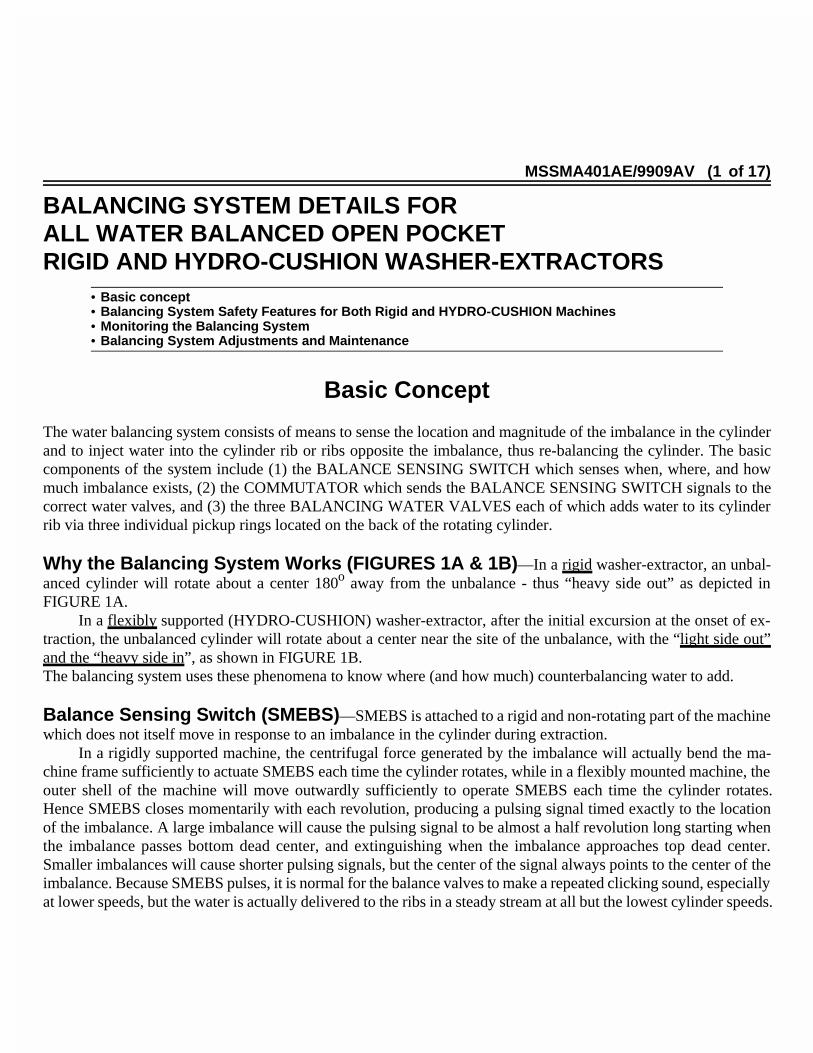
The water balancing system consists of means to sense the location and magnitude of the imbalance in the cylinderand to inject water into the cylinder rib or ribs opposite the imbalance, thus re-balancing the cylinder. The basiccomponents of the system include (1) the BALANCE SENSING SWITCH which senses when, where, and howmuch imbalance exists, (2) the COMMUTATOR which sends the BALANCE SENSING SWITCH signals to thecorrect water valves, and (3) the three BALANCING WATER VALVES each of which adds water to its cylinderrib via three individual pickup rings located on the back of the rotating cylinder.
ËWhy the Balancing System Works (FIGURES 1A & 1B) —In a rigid washer-extractor, an unbal-anced cylinder will rotate about a center 180o away from the unbalance - thus “heavy side out” as depicted inFIGURE 1A.
In a flexibly supported (HYDRO-CUSHION) washer-extractor, after the initial excursion at the onset of ex-traction, the unbalanced cylinder will rotate about a center near the site of the unbalance, with the “light side out”and the “heavy side in”, as shown in FIGURE 1B.The balancing system uses these phenomena to know where (and how much) counterbalancing water to add.
ËBalance Sensing Switch (SMEBS) —SMEBS is attached to a rigid and non-rotating part of the machinewhich does not itself move in response to an imbalance in the cylinder during extraction.
In a rigidly supported machine, the centrifugal force generated by the imbalance will actually bend the ma-chine frame sufficiently to actuate SMEBS each time the cylinder rotates, while in a flexibly mounted machine, theouter shell of the machine will move outwardly sufficiently to operate SMEBS each time the cylinder rotates.Hence SMEBS closes momentarily with each revolution, producing a pulsing signal timed exactly to the locationof the imbalance. A large imbalance will cause the pulsing signal to be almost a half revolution long starting whenthe imbalance passes bottom dead center, and extinguishing when the imbalance approaches top dead center.Smaller imbalances will cause shorter pulsing signals, but the center of the signal always points to the center of theimbalance. Because SMEBS pulses, it is normal for the balance valves to make a repeated clicking sound, especiallyat lower speeds, but the water is actually delivered to the ribs in a steady stream at all but the lowest cylinder speeds.
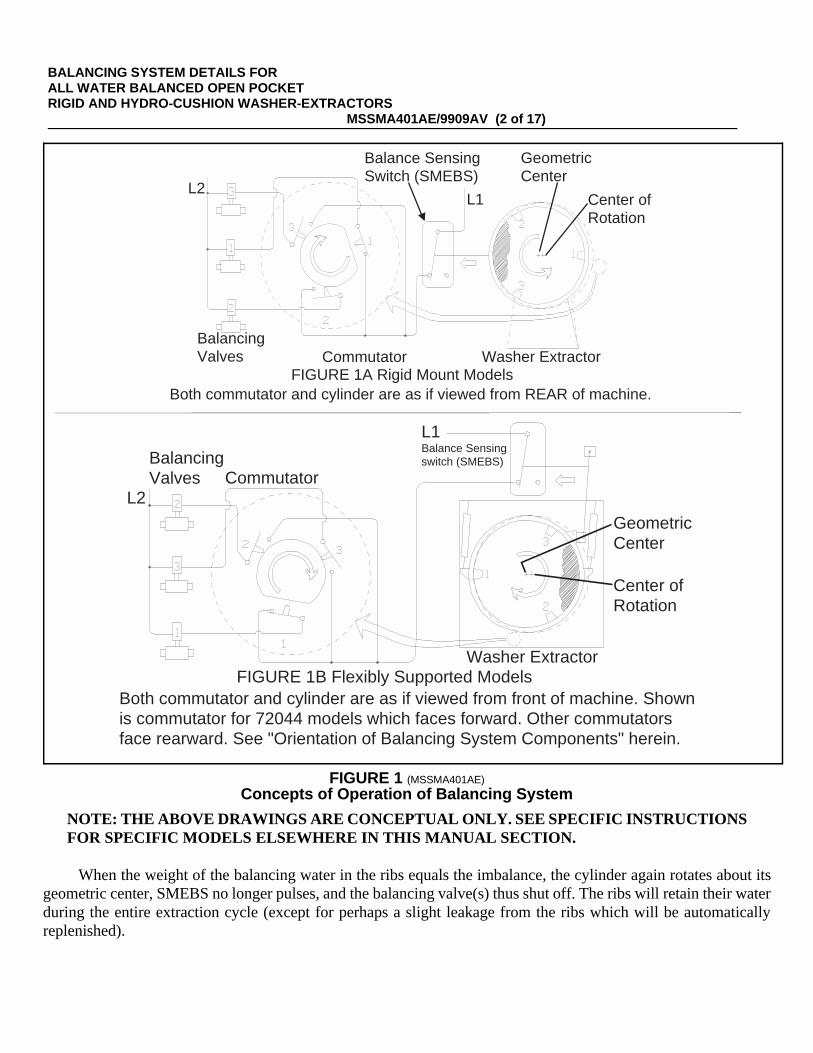
NOTE: THE ABOVE DRAWINGS ARE CONCEPTUAL ONLY. SEE SPECIFIC INSTRUCTIONSFOR SPECIFIC MODELS ELSEWHERE IN THIS MANUAL SECTION.
When the weight of the balancing water in the ribs equals the imbalance, the cylinder again rotates about itsgeometric center, SMEBS no longer pulses, and the balancing valve(s) thus shut off. The ribs will retain their waterduring the entire extraction cycle (except for perhaps a slight leakage from the ribs which will be automaticallyreplenished).
L2L1
Balance SensingSwitch (SMEBS)
GeometricCenter
Center ofRotation
Washer ExtractorBalancingValves Commutator
FIGURE 1A Rigid Mount ModelsBoth commutator and cylinder are as if viewed from REAR of machine.
BalancingValves Commutator
L1Balance Sensingswitch (SMEBS)
GeometricCenter
Center ofRotation
Washer ExtractorFIGURE 1B Flexibly Supported Models
Both commutator and cylinder are as if viewed from front of machine. Shownis commutator for 72044 models which faces forward. Other commutatorsface rearward. See "Orientation of Balancing System Components" herein.
L2
ÎFIGURE 1 (MSSMA401AE)
ÎConcepts of Operation of Balancing System
BALANCING SYSTEM DETAILS FOR ALL WATER BALANCED OPEN POCKET RIGID AND HYDRO-CUSHION WASHER-EXTRACTORS
MSSMA401AE/9909AV (2 of 17)

ËWhat the Commutator Does (FIGURE 2) —The pulsing SMEBS signal is sent through a “commuta-tor” (shown in FIGURE 1) which has a separate cam operated switch for each of the three balancing water valves.Each valve can add water to one of the three cylinder ribs. The cam turns at the same speed and direction as thewasher cylinder and thus always sends the SMEBS signal to the correct valve(s).
FIGURES 1A and 1B depict the imbalance exactly opposite rib #1 so the nearly half- revolution SMEBSsignal persists only while commutator switch #1 is closed - thus sending balancing water only to rib #1. If theimbalance falls closer to one rib, (for example, closer to rib #1 as depicted in FIGURE 2) at first both ribs #2 and#3 will receive water at the same rate. However, the added water in the rib nearest the imbalance, together with theoriginal imbalance itself, will cause the resultant center of mass of the imbalance to shift opposite rib #2 - shuttingoff the water to rib #3 valve first, and permitting additional water to be added only into the farthest rib (rib #2 inFIGURE 2) until complete balance is achieved.
ËHow the Water Enters the Ribs —The water from each balancing valve enters its respective rib via aninjection nozzle which is aimed into its respective pickup ring on the back of the cylinder. See FIGURE 12, “Ori-entation of Balance System Components” and FIGURE 13, “Aiming the Balancing Nozzles” elsewhere herein forfurther information.
Desired counterbalancebetween ribs 2 and 3but closer to rib 2
Fills
Fills
Desired counterbalancecentered on rib 2
Imbalance mass pluswater in nearest ribcausing resultantimbalance to beexactly oppositethe farthest rib
StopsFilling
ContinuesFilling
Out of balancenext to Rib 1
Out of balanceshifts toward Rib 3
ÎFIGURE 2 (MSSMA401AE)
ÎHow Water is Used to Counter an Imbalance
BALANCING SYSTEM DETAILS FOR ALL WATER BALANCED OPEN POCKET RIGID AND HYDRO-CUSHION WASHER-EXTRACTORS
MSSMA401AE/9909AV (3 of 17)

ËAiming the Balancing Water Nozzles (FIGURE 13) —When properly aimed and adjusted, thewater nozzles correctly deliver the balancing water from each balancing water valve to its respective pickup ringwhich admits the water to the appropriate rib. If not aimed and adjusted correctly, the water may splash (or fall) intothe wrong pickup ring and thus enter the wrong rib, rendering the system unworkable. See FIGURE 13 for how thenozzles should be aimed and adjusted in each model.
ËHow the Balance Sensing Device Works (FIGURES 3 & 8) —The Balance Sensing Switch(SMEBS) is not actually actuated directly by the shell of the washer-extractor as depicted in diagrammatic FIG-URES 1A and 1B. Instead, a Balance Sensing Device (FIGURES 3 & 8) is interposed between the shell andSMEBS. Its purpose is to amplify the extraction deflections or excursions caused by an imbalance. The BalanceSensing Device also actuates a second switch which is called a Coast Sensing Switch (SMERC) in rigid machinesand a Coarse Balance Switch (SMERC) in flexibly supported (HYDRO-CUSHION) machines.
The Balance Sensing Device also has an adjustablebypass needle valve which permits the oil betweenthe diaphragms to flow back and forth from the oilreservoir when the driving diaphragm is movedslowly, as under the influence of temperature-causeddimension changes, while the spring-biased drivendiaphragm remains stationary against its stop. Thusthe switches are not actuated by small, or slow,movements. The sensitivity of the Balance SensingDevice is affected by 1)the viscosity of the oil and 2)how much the bypass valve is open.
ÎFIGURE 3 (MSSMA401AE)
ÎChecking Balance Sensing Device Oil Levels
BALANCING SYSTEM DETAILS FOR ALL WATER BALANCED OPEN POCKET RIGID AND HYDRO-CUSHION WASHER-EXTRACTORS
MSSMA401AE/9909AV (4 of 17)

ÊBalancing System Safety Featuresfor Both Rigid and HYDRO-CUSHION Machines
Various safety features are incorporated into the balancing system to protect against damage and unsafe op-eration resulting from severe out of balance loads.
ËFor Rigid Models 30016 & 36021 OnlyCoast Safety Switch (FIGURE 8)—If the imbalance is more than the balance system can counteract, this
coarser set switch will be actuated as the cylinder accelerates. Each time it is actuated, the cylinder will coast for 7.5seconds - thus reducing the maximum extraction speed commensurate with a safe unbalance force. (The entireextraction may thus continue at a lower speed if the balancing system never catches up with the imbalance.)
ËFor Microprocessor HYDRO-CUSHION Models 48032, 64042, and 72044 OnlyRecycle Circuit—The recycle circuit automatically redistributes an excessively out of balance load. It be-
comes operational when extract commences and may be actuated by the Excursion Switch (SMERB, FIGURE 4)or the Coarse Balance Switch (SMERC, see FIGURE 8). Although the Excursion Switch will initiate recycle anytime it is actuated during extraction, the primary purpose of this switch is to sense an excessive imbalance duringthe onset of extraction. The Coarse Switch initiates recycle only if an imbalance exceeds a certain permissible levela few seconds after the onset of high extract speed.
The Excursion switch actuator, FIGURE 4, must be exactly in the center of the slotted hole - bothwhen the machine is pushed down and when it is hanging free. If not, the switch will actuateprematurely, during the initial excursion, at the onset of extraction, causing unnecessary recy-cles. See “HOW THE EXCURSION SWITCH WORKS” elsewhere.
When recycle is initiated, the cylinder comes to a full stop,it then rotates 16 seconds CCW in wash speed, 7.5 secondsin CW wash speed, 7.5 seconds in drain speed, and thenre-enters extract. During recycle, program timing stops,and starts again 7.5 seconds after high extract has againbeen allowed. Microprocessor controlled models will re-cycle 5 times, then repeat the final bath (without chemi-cals) and re-enter extraction.
ËFor MARK 4 MILTROL HYDRO-CUSHIONModel 72044 Only
Recycle Circuit—The recycle circuit automaticallyredistributes an excessively out of balance load. It be-comes operational when extract commences and may beactuated by the Excursion Switch (SMERB). Although theExcursion Switch will initiate recycle any time it is actu-ated during extraction, the primary purpose of this switchis to sense an excessive imbalance during the onset of ex-
ÎFIGURE 4 (MSSMA401AE)
ÎExcursion Switch
BALANCING SYSTEM DETAILS FOR ALL WATER BALANCED OPEN POCKET RIGID AND HYDRO-CUSHION WASHER-EXTRACTORS
MSSMA401AE/9909AV (5 of 17)

traction. When recycle is initiated, the cylinder comes to a full stop, it thenrotates 16 seconds CCW in wash speed, 7.5 seconds in CW wash speed, 7.5seconds in drain speed, and then re-enters extract. During recycle, programtiming stops, and starts again 7.5 seconds after high extract has again beenallowed.
In these MILTROL controlled models, the machine will stop (3-wirerelay is disabled) should the Coarse Balance Switch be actuated after E2(high extract speed) has commenced.
ËFor Both Rigid and HYDRO-CUSHION ModelsVibration Circuit —The Vibration Safety Switch (FIGURE 5) reacts
to excessive vibration which is not contained by the balancing system, ac-tuating a switch which de-energizes the 3 wire relay, shutting off power tothe machine. When this occurs, the cause of the vibration should be deter-mined and corrected. The start switch must be depressed to resume opera-tion. See “VIBRATION SAFETY SWITCH ADJUSTMENTS”elsewhere.
ÎFIGURE 5 (MSSMA401AE)
ÎVibration Safety Switch
BALANCING SYSTEM DETAILS FOR ALL WATER BALANCED OPEN POCKET RIGID AND HYDRO-CUSHION WASHER-EXTRACTORS
MSSMA401AE/9909AV (6 of 17)
ÊMonitoring the Balancing SystemA panel of status lights is provided to monitor the functioning of the balancing system. This light panel is
located on the front of HYDRO-CUSHION models and on a junction box on the rear or side of rigid mount models.
ËBalance Sensing Switch Light —Remains ON so long as the Balance Sensing Switch is not actuated andshould never stay OFF while the machine is extracting. This light will normally flicker during extraction, bothbefore and after balancing is achieved.
A continuous flashing during an occasional extraction indicates that the imbalance exceeds the machine’scounter-balancing capacity.
A continuous flashing over repeated extractions may indicate 1) inadequate water supply or 2) need to servicethe balancing system.
ËBalancing Valve Lights —These three lights go ON and OFF with their respective balancing valves. Lightsshould be OFF once balancing is completed, except for intermittent valve operation as the balancing system com-pensates for changing imbalance (caused by varying load thicknesses, different absorption rates, etc.). A continuousflashing over repeated extractions may indicate 1) inadequate water supply or 2) need to service the balancingsystem. If water is required in two of the three ribs, two of these lights may flash sequentially, but never in unison(i.e., the lights must always turn on or off one after the other, and must never turn on or off simultaneously).Moreover, all three lights must never flash either sequentially or in unison, except for a brief moment at the onsetof low speed extraction, and again at the onset of high speed extraction. At all other times, only one or two of thethree lights should flash until balance is achieved, never all three.
ËBalance Excursion Light ( Microprocessor, Rigid Mount Models Only) andExtract Motor Light ( MILTROL, Rigid Mount Models Only) —This light goes ON and OFF withthe extract motor and is used to monitor the Coast circuit. Up to six coasts are normal at the beginning of an extract,but ordinarily, the machine should not coast after it has been extracting for two minutes unless the imbalanceexceeds the machine’s counter-balancing capacity. In this event, the machine will coast throughout the entire ex-traction. Frequent or repetitive coasting throughout most extractions may indicate inadequate water supply or needto service the balancing system.
ËBalance Excursion Light ( Microprocessor, HYDRO-CUSHION Models Only) — T h i slight is located on the balance sensing device (and thus not visible on the machine exterior). It illuminates whenextract is desired and extinguishes whenever the Coarse Balance Switch actuates. Actuation of the Coarse BalanceSwitch will cause a recycle if it occurs within 8 seconds after high extract is called for or between 16 seconds and2 minutes after high extract is called for.
ËHigh Speed Extract Light (MILTROL, HYDRO-CUSHION Models Only) —Illuminates atthe end of low speed extract, indicating that high extract is desired. The light will flash if an imbalance exceeds themachine counter-balancing capacity and extinguish while recycle is in progress. If the light remains steady ONindicating that high extract is allowed, the machine will begin to accelerate to high extract speed approximately 8.5seconds after the light illuminates steadily.
BALANCING SYSTEM DETAILS FOR ALL WATER BALANCED OPEN POCKET RIGID AND HYDRO-CUSHION WASHER-EXTRACTORS
MSSMA401AE/9909AV (7 of 17)

ÊBalancing System Adjustments and MaintenanceAll components of the balancing system are properly set and tested at the factory and should not need read-
justment when the equipment is installed. If however, as a result of improper handling in shipment or installationand when as a normal consequence of use it becomes necessary to readjust this system, the following proceduresshould be observed. Before proceeding, review the published safety precautions for this machine. The followingprocedures apply to all machine models except where noted otherwise.
ELECTRIC SHOCK HAZARD—Except where noted otherwise, the following adjustments shouldbe done with power locked OFF and tagged out at the machine disconnect switch (on the wall).
ËBalance Sensing Device Oil Level (FIGURE 3) —The oil level in this device should be visuallychecked daily and replenished if it drops below the recommended level. The Balance Mechanism will not functionif the oil level drops where air enters the fluid housing. If this is suspected, proceed as follows:
1. To check for air in the fluid housing, remove the plug on top of the housing. Oil should immediately beginflowing out of the hole if there is no trapped air in the unit. If oil does not flow out, make sure the bypassvalve is open, and then add oil through the oil reservoir until it does flow out. Quickly replace the plug onceoil begins to flow out.
2. The reservoir should be filled approximately half full. Use a good grade of 15W-40 motor oil. Note that 1) oilmust always be added to the reservoir, never directly through the plug on top of the mechanism housing, 2)the reservoir must not be filled completely, to allow space for oil flowing out of the fluid housing duringslow movement of the driving diaphragm, 3) the oil reservoir plug must be a vented plug and the plug onthe mechanism housing must be non-vented, and 4) there must be no entrapped air in between the two dia-phragms.
3. Check the needle valve setting per Table A below. The more it is open, the less sensitive the unit will be. It ispossible to open the needle valve so wide as to render the unit completely insensitive to vibration. Theplunger attached to the driven (small) diaphragm should not move while the machine is operating at wash ordrain speed, but a rise and fall of the oil in the gauge during washing and draining may be observed.
ÏTABLE ABypass Needle Valve Settings by Model Number
30016 36021 48032 64042 72044
1-1/2 1-1/2 1-1/2 1-1/2 4Data shown is number of turns open
BALANCING SYSTEM DETAILS FOR ALL WATER BALANCED OPEN POCKET RIGID AND HYDRO-CUSHION WASHER-EXTRACTORS
MSSMA401AE/9909AV (8 of 17)

ELECTRIC SHOCK HAZARD—When the machine power is on, the exposed terminals on theswitches in the Balance Sensing Device may be energized up to 250 VAC. You can be killed orseverely injured by contact with these energized conductors.
☞ Make certain power is locked OFF and tagged out at the external disconnect switch (onthe wall) before servicing the Balancing Sensing Device.
☞ Do not touch the switch terminals or the wires going to them when servicing the BalanceSensing Device.
☞ When adjusting the Balancing Sensing Device on a HYDRO-CUSHION Machine, it isimportant to have machine power off because the cylinder must be hanging free, notpushed down.
ËOuter (Driving) Diaphragm Adjustment (FIGURE 6) —This diaphragm must be centered as shownin FIGURE 6A. Note that the total length of travel of the input shaft is approximately 1/32" (0.8mm) in rigid modelsand about 1/8" (3.2mm) in HYDRO-CUSHION models. If adjustment is necessary, loosen the nuts on each side ofthe arm to which the shaft is attached and extend or retract the shaft as required to reposition it at the center of travel.There must never be a ripple or wavy condition in the driving diaphragm as this will seriously lessen the sensitivityof the unit.
On HYDRO-CUSHION models, the conditions shown in FIGURE 6B and 6C are prevented by prop-erly aligning the Balance Sensing Device actuator bar and properly setting the bar springs. See instructionsand Caution on next page.
FIGURE 6A - CORRECT FIGURE 6B - INCORRECT FIGURE 6C - INCORRECT
ÎFIGURE 6 (MSSMA401AE)
ÎDriving Diaphragm Alignment
BALANCING SYSTEM DETAILS FOR ALL WATER BALANCED OPEN POCKET RIGID AND HYDRO-CUSHION WASHER-EXTRACTORS
MSSMA401AE/9909AV (9 of 17)

Ë(FOR HYDRO-CUSHION Models Only) Aligning the Balance Sensing DeviceActuator Bars and Setting the Horizontal Bar Springs (FIGURE 7)
1. Align vertical bar perpendicular to Sensing Device.
2. Align vertical bar lower ball joint, apply Loctite andtighten.
3. Set horizontal bar springs as per Table B below.
With the machine hanging free, the compressedheight of both springs must be equal and the dia-phragm must be centered as depicted in FIGURE6A, not pulled to one side as in FIGURE 6B or 6C.
ÏTABLE BHorizontal Bar Springs Setting
30016 36021 48032 64042 72044
N/A N/A 15/16"(24mm)
2"(51mm)
3-7/8"(98mm)
ËInner (Drive) Diaphragm Replacement —Although the driven diaphragm is available as a repair part,its installation is not very simple because there must never be a ripple or wavy condition in the driving diaphragmas this will seriously lessen the sensitivity of the unit. The mating dished surfaces of the plunger and the washerserve to stretch the diaphragm for this purpose. Should a new driven diaphragm be field-installed, be sure that thiscondition does not occur. (Since the driven diaphragm rarely fails as long as the balancing system is retained inproper working order, it is usually better to install a new assembly should the need ever arise.)
Horizontal Bar Springs
BalanceSensingDevice
Lower Ball Joint
See Table Bfor dimension
ÎFIGURE 7 (MSSMA401AE)
ÎAdjusting the Actuator Bar Assembly
BALANCING SYSTEM DETAILS FOR ALL WATER BALANCED OPEN POCKET RIGID AND HYDRO-CUSHION WASHER-EXTRACTORS
MSSMA401AE/9909AV (10 of 17)

ËAdjusting the Switches on the Balance Sensing Device (FIGURE 8) —This device must beadjusted so that the Balance Sensing Switch (SMEBS) and the Coast Sensing Switch or Coarse Balance Switch(SMERC) will actuate when the driven diaphragm plunger has travelled a certain distance. These adjustments areas follows.
ËSetting the Balance Sensing Switch (SMEBS)
1. Connect an ohm meter across the common and the normally open terminals on the Balance Sensing SwitchSMEBS. See FIGURE 9 to identify the common and the normally open terminals on this switch. The ohmmeter should read a finite resistance (a resistance significantly greater than zero) - or turn the balance sens-ing screw CCW until a finite resistance is read. Now actuate the SMEBS by hand and observe that the resis-tance goes to substantially zero, (thus indicating that the normally open contacts have closed and only theresistance of the closed contacts themselves is being read by the meter).
NOTE: If the plunger on SMEBS is free (not depressed) and a finite resistance cannot be read, the switchis shorted closed and must be replaced.
2. Next, slowly turn the balance sensing screw CW until the ohm meter resistance reads zero. (This will happenwhen the common and normally open contacts on SMEBS close.)
3. Now slowly turn the balance sensing screw CCW until the ohm meter again reads a finite resistance. (Thispoint is where the normally open contact on SMEBS has just opened.)
4. Now turn the balance sensing screw CCW the additional number of turns mentioned in TABLE C below.
ÏTABLE CAdjusting the Balance Sensing Switch
(number of additional CCW turns of Balance Sensing Screwafter the normally open contact on SMEBS has just opened)
30016 36021 48032 64042 72044
1/4 1/4 1-3/4 1-1/2 4-3/4
5. While holding the balance sensing screw in position, tighten the lock nut, verify that this does not cause thescrew to turn otherwise the adjustment will be lost.
BALANCING SYSTEM DETAILS FOR ALL WATER BALANCED OPEN POCKET RIGID AND HYDRO-CUSHION WASHER-EXTRACTORS
MSSMA401AE/9909AV (11 of 17)

ËSetting The Coast Sensing Switch (SMERCif a Rigid Machine) or the Coarse BalanceSwitch (SMERC if a HYDRO-CUSHIONMachine) —Connect an ohm meter across the normallyopen terminals on the Coast Sensing Switch or the Coarse Bal-ance Switch. The ohm meter should read a finite resistance (aresistance significantly greater than zero). Now adjust theCoast (Coarse) Switch by turning the adjusting nut which islocated on the driven diaphragm plunger as shown in FIGURE8 - so that when a feeler gauge of the thickness mentioned inTable D below is inserted where shown on FIGURE 8, the ohmmeter resistance becomes substantially zero, thus indicatingthat the normally open contacts have closed and only the resis-tance of the closed contacts themselves is being read by themeter.
ÏTABLE DFeeler Gauge Thickness Required
when Setting Coast (Coarse) Switch
30016 36021 48032 64042 72044
.010"(0.254mm)
.010"(0.254mm)
.015"(0.381mm)
.015"(0.381mm)
.027"(0.686mm)
ÎFIGURE 8 (MSSMA401AE)
ÎAdjusting the Balance Sensing Device
Volt meterprobe orwire withsmall amountof insulationremoved
BalanceSensingDevice
NormallyClosed
Coast (Coarse)Switch
BalanceSensingSwitch
Common
NormallyOpen
ÎFIGURE 9 (MSSMA401AE)
ÎAccessing Terminals on MicroSwitches
BALANCING SYSTEM DETAILS FOR ALL WATER BALANCED OPEN POCKET RIGID AND HYDRO-CUSHION WASHER-EXTRACTORS
MSSMA401AE/9909AV (12 of 17)

ËAdjusting the Commutator
NOTE: The following adjustment procedure is equally applicable to both rigidly mounted and flexiblysupported (HYDRO-CUSHION) models.
ELECTRIC SHOCK HAZARD—Except where noted otherwise, the following adjustments shouldbe made only with power locked OFF and tagged out at the external disconnect switch (on thewall).
ËSetting the Gap in the Commutator Switch Breaker Points (FIGURE 10)
Each breaker point gap must be .015" (0.38mm) when the plastic cam fol-lower on the switch is riding on the high portion of the cam. Precise breakerpoint gaps are necessary both to insure the proper current interruption whenthe switch is open, and also to adjust the switch so that it remains closed theexact portion of one complete cylinder revolution that is necessary forproper operation of the balancing device. Both adjustments are simultane-ously achieved when the breaker points are set at .015" (0.38mm) open, asdescribed below.
ELECTRIC SHOCK HAZARD—Since it is necessary to use power to rotate the cylinder, station asafety lookout behind the machine to guard against someone accidentally touching the high volt-age in commutator while power is ON.Be sure electric power to the machine is OFF at the wall disconnect before removing or replacingthe commutator cover, and before touching anything inside the commutator.
1. Rotate cylinder until cam follower is riding on large diameter of cam.
2. Loosen the breaker point mounting screws and insert a .015" (0.38mm) feeler gauge between the contacts(FIGURE 10).
3. Tighten the mounting screws, checking to insure that the gap clearance does not change while the screws arebeing tightened. (Readjust if necessary. Breaker point clearance must be .015" (0.38mm).
4. Repeat this procedure for each of the three breaker point switches.
.015"(0.38mm)gap
Plastic Cam Follower
ÎFIGURE 10 (MSSMA401AE)
ÎBreaker Point SwitchSetting
BALANCING SYSTEM DETAILS FOR ALL WATER BALANCED OPEN POCKET RIGID AND HYDRO-CUSHION WASHER-EXTRACTORS
MSSMA401AE/9909AV (13 of 17)

ËTiming the Commutator (FIGURES 11A & 11B) —The Commutator must be timed so that the flaton the cam is in the proper relationship to the ribs in the cylinder. For example, (FIGURE 11A) when the #1 rib isin the 9 o’clock position as viewed from the front (through the door), the flat on the cam must be exactlycentered under the cam follower for the #1 switch as shown in FIGURE 11B.
Refer to FIGURE 12 “Orientation of Balancing System Components” (elsewhere herein), before reading paragraphs A & B following.
A. Rib numbers are identified by punch marks (1, 2 or 3) on top of each rib, near the front of the basket.
If the rib number marks have worn away, one can still readily determine the rib number by determining itspickup ring. To do this, remove the hand holes on the rear of the machine to gain access to the pickup ring.Now use a bent coat hanger to find the radial hole in the pickup ring that communicates with one of the ribs,and identify the rib number by referring to the appropriate chart in FIGURE 12 “Orientation of BalancingSystem Components.” This is necessary because the location of the pickup rings is not the same for all mod-els.
B. Depending on the machine model, the commutator switches will be numbered either 1, 2, and 3 or A1, B2,and C3. On some models the commutator faces rearward and thus is seen to rotate counter-clockwise in ex-traction when viewed from the rear while the cylinder is seen to rotate clockwise in extraction when viewedfrom the front. On other models, the commutator faces forward and is thus seen to rotate clockwise in extrac-tion, the same as the cylinder. (The cylinder always rotates clockwise in extract when viewed from front.)
ÎFIGURE 11 (MSSMA401AE)
ÎTiming the Commutator
BALANCING SYSTEM DETAILS FOR ALL WATER BALANCED OPEN POCKET RIGID AND HYDRO-CUSHION WASHER-EXTRACTORS
MSSMA401AE/9909AV (14 of 17)

ÎFIGURE 12 (MSSMA401AE)
ÎOrientation of Balancing System Components
BALANCING SYSTEM DETAILS FOR ALL WATER BALANCED OPEN POCKET RIGID AND HYDRO-CUSHION WASHER-EXTRACTORS
MSSMA401AE/9909AV (15 of 17)

When the commutator is properly timed, each time a rib passes the 9 o’clock position as viewed throughthe door, the exact center of the flat on the cam will be passing under the center of the switch follower for thatrib. If not, the cam must be repositioned by rotating it about its shaft. To do this, proceed as follows:
1. Make sure that the timing belt drive is properly adjusted without excessive slack (but not "banjo string" tight).Excessive slack in the timing belt will permit the belt cogs to slip over the ridges on the pulleys and put theunit “out-of-time”.
2. Rotate the empty cylinder until any rib is exactly in the 9 o’clock position. In other words, the rib should be tothe left when facing the front of the machine and an imaginary line drawn from the center of the rib to thecenter of the cylinder should exactly parallel the floor. (FIGURE 11A shows rib #1 at the 9 o’clock positionbut any rib will do as long as the rib number is known.)
ELECTRIC SHOCK HAZARD—Since it is necessary to use power to rotate the cylinder, station asafety lookout behind the machine to guard against someone accidentally touching the high volt-age in the commutator while the power is ON.Be sure electric power to the machine is OFF at the wall disconnect before removing or replacingthe commutator cover, and before touching anything inside the commutator.
3. Loosen the commutator cam lock nut and rotate the cam so its flat is exactly centered under the follower forthat rib switch. (FIGURE 11B shows the flat exactly under the switch for rib #1 - thus corresponding to theillustration in FIGURE 11A.)
4. While holding the cam, re-tighten the lock nut making sure the cam does not turn as the lock nut is tightened.
5. Recheck cam alignment before replacing the commutator cover. Re-adjust the cam if necessary.
ËLubricating the Commutator Cam and Breaker Points —The commutator switches are actuallyspecial automobile breaker points and, as in automobiles, must be lubricated, otherwise the surface of both the camand the plastic cam follower will wear, closing the switch gaps and rendering the balancing system inoperative. Useenough lubricant to coat the cam surface and to build up a small deposit of the lubricant on each plastic camfollower. A tube of cam lubricant (MILNOR P/N 20H016) was supplied with the machine, and should last manyyears.
BALANCING SYSTEM DETAILS FOR ALL WATER BALANCED OPEN POCKET RIGID AND HYDRO-CUSHION WASHER-EXTRACTORS
MSSMA401AE/9909AV (16 of 17)
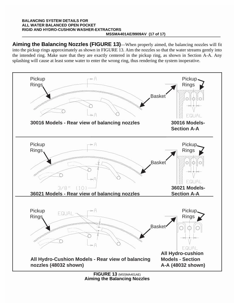
ËAiming the Balancing Nozzles (FIGURE 13) —When properly aimed, the balancing nozzles will fitinto the pickup rings approximately as shown in FIGURE 13. Aim the nozzles so that the water streams gently intothe intended ring. Make sure that they are exactly centered in the pickup ring, as shown in Section A-A. Anysplashing will cause at least some water to enter the wrong ring, thus rendering the system inoperative.
PickupRings
PickupRings
Basket
PickupRings
PickupRings
PickupRings
Basket
Basket
PickupRings
30016 Models - Rear view of balancing nozzles
36021 Models - Rear view of balancing nozzles
All Hydro-Cushion Models - Rear view of balancingnozzles (48032 shown)
All Hydro-cushionModels - SectionA-A (48032 shown)
36021 Models-Section A-A
30016 Models-Section A-A
ÎFIGURE 13 (MSSMA401AE)
ÎAiming the Balancing Nozzles
BALANCING SYSTEM DETAILS FOR ALL WATER BALANCED OPEN POCKET RIGID AND HYDRO-CUSHION WASHER-EXTRACTORS
MSSMA401AE/9909AV (17 of 17)