
BALANCING OF ROTATING MASSES - Atria | e-Learning | · PDF file ·...
46
VTU EDUSAT PROGRAMME - 17 DYNAMICS OF MACHINES VIJAYAVITHAL BONGALE DYNAMICS OF MACHINES Subject Code -10 ME 54 BALANCING OF ROTATING MASSES INTRODUCTION: When man invented the wheel, he very quickly learnt that if it wasn’t completely round and if it didn’t rotate evenly about it’s central axis, then he had a problem! What the problem he had? The wheel would vibrate causing damage to itself and it’s support mechanism and in severe cases, is unusable. A method had to be found to minimize the problem. The mass had to be evenly distributed about the rotating centerline so that the resultant vibration was at a minimum. UNBALANCE: The condition which exists in a rotor when vibratory force or motion is imparted to its bearings as a result of centrifugal forces is called unbalance or the uneven distribution of mass about a rotor’s rotating centerline. Notes Compiled by: VIJAYAVITHAL BONGALE ASSOCIATE PROFESSOR DEPARTMENT OF MECHANICAL ENGINEERING MALNAD COLLEGE OF ENGINEERING HASSAN -573 202. KARNATAKA Mobile:9448821954 E-mail:[email protected]
Transcript of BALANCING OF ROTATING MASSES - Atria | e-Learning | · PDF file ·...
VTU EDUSAT PROGRAMME - 17
DYNAMICS OF MACHINES VIJAYAVITHAL BONGALE
DYNAMICS OF MACHINES Subject Code -10 ME 54
BALANCING
OF ROTATING MASSES
INTRODUCTION:
When man invented the wheel, he very quickly learnt that if it wasn’t completely round
and if it didn’t rotate evenly about it’s central axis, then he had a problem!
What the problem he had?
The wheel would vibrate causing damage to itself and it’s support mechanism and in
severe cases, is unusable.
A method had to be found to minimize the problem. The mass had to be evenly
distributed about the rotating centerline so that the resultant vibration was at a minimum.
UNBALANCE:
The condition which exists in a rotor when vibratory force or motion is imparted to its
bearings as a result of centrifugal forces is called unbalance or the uneven distribution of
mass about a rotor’s rotating centerline.
Notes Compiled by:
VIJAYAVITHAL BONGALE
ASSOCIATE PROFESSOR
DEPARTMENT OF MECHANICAL ENGINEERING
MALNAD COLLEGE OF ENGINEERING
HASSAN -573 202. KARNATAKA
Mobile:9448821954
E-mail:[email protected]
VTU EDUSAT PROGRAMME - 17
DYNAMICS OF MACHINES VIJAYAVITHAL BONGALE
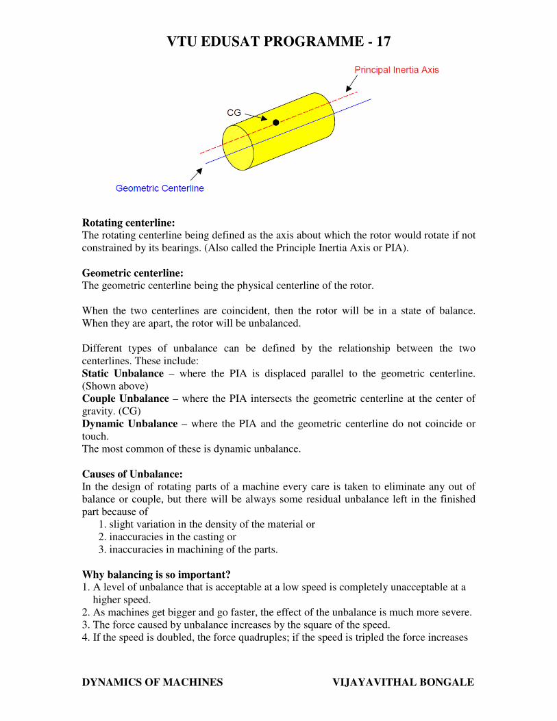
Rotating centerline:
The rotating centerline being defined as the axis about which the rotor would rotate if not
constrained by its bearings. (Also called the Principle Inertia Axis or PIA).
Geometric centerline:
The geometric centerline being the physical centerline of the rotor.
When the two centerlines are coincident, then the rotor will be in a state of balance.
When they are apart, the rotor will be unbalanced.
Different types of unbalance can be defined by the relationship between the two
centerlines. These include:
Static Unbalance – where the PIA is displaced parallel to the geometric centerline.
(Shown above)
Couple Unbalance – where the PIA intersects the geometric centerline at the center of
gravity. (CG)
Dynamic Unbalance – where the PIA and the geometric centerline do not coincide or
touch.
The most common of these is dynamic unbalance.
Causes of Unbalance:
In the design of rotating parts of a machine every care is taken to eliminate any out of
balance or couple, but there will be always some residual unbalance left in the finished
part because of
1. slight variation in the density of the material or
2. inaccuracies in the casting or
3. inaccuracies in machining of the parts.
Why balancing is so important?
1. A level of unbalance that is acceptable at a low speed is completely unacceptable at a
higher speed.
2. As machines get bigger and go faster, the effect of the unbalance is much more severe.
3. The force caused by unbalance increases by the square of the speed.
4. If the speed is doubled, the force quadruples; if the speed is tripled the force increases
VTU EDUSAT PROGRAMME - 17
DYNAMICS OF MACHINES VIJAYAVITHAL BONGALE
by a factor of nine!
Identifying and correcting the mass distribution and thus minimizing the force and
resultant vibration is very very important
BALANCING:
Balancing is the technique of correcting or eliminating unwanted inertia forces or
moments in rotating or reciprocating masses and is achieved by changing the location of
the mass centers.
The objectives of balancing an engine are to ensure:
1. That the centre of gravity of the system remains stationery during a complete
revolution of the crank shaft and
2. That the couples involved in acceleration of the different moving parts
balance each other.
Types of balancing:
a) Static Balancing:
i) Static balancing is a balance of forces due to action of gravity.
ii) A body is said to be in static balance when its centre of gravity is in the
axis of rotation.
b) Dynamic balancing:
i) Dynamic balance is a balance due to the action of inertia forces.
ii) A body is said to be in dynamic balance when the resultant moments or
couples, which involved in the acceleration of different moving parts is
equal to zero.
iii) The conditions of dynamic balance are met, the conditions of static
balance are also met.
In rotor or reciprocating machines many a times unbalance of forces is produced due to
inertia forces associated with the moving masses. If these parts are not properly balanced,
the dynamic forces are set up and forces not only increase loads on bearings and stresses
in the various components, but also unpleasant and dangerous vibrations.
Balancing is a process of designing or modifying machinery so that the unbalance is
reduced to an acceptable level and if possible eliminated entirely.
BALANCING OF ROTATING MASSES
When a mass moves along a circular path, it experiences a centripetal acceleration and a
force is required to produce it. An equal and opposite force called centrifugal force acts
radially outwards and is a disturbing force on the axis of rotation. The magnitude of this
remains constant but the direction changes with the rotation of the mass.
VTU EDUSAT PROGRAMME - 17
DYNAMICS OF MACHINES VIJAYAVITHAL BONGALE
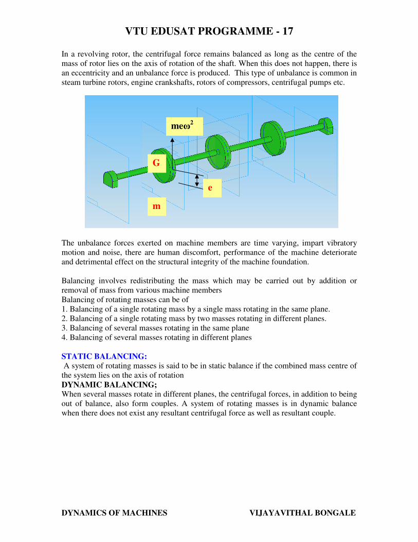
In a revolving rotor, the centrifugal force remains balanced as long as the centre of the
mass of rotor lies on the axis of rotation of the shaft. When this does not happen, there is
an eccentricity and an unbalance force is produced. This type of unbalance is common in
steam turbine rotors, engine crankshafts, rotors of compressors, centrifugal pumps etc.
The unbalance forces exerted on machine members are time varying, impart vibratory
motion and noise, there are human discomfort, performance of the machine deteriorate
and detrimental effect on the structural integrity of the machine foundation.
Balancing involves redistributing the mass which may be carried out by addition or
removal of mass from various machine members
Balancing of rotating masses can be of
1. Balancing of a single rotating mass by a single mass rotating in the same plane.
2. Balancing of a single rotating mass by two masses rotating in different planes.
3. Balancing of several masses rotating in the same plane
4. Balancing of several masses rotating in different planes
STATIC BALANCING:
A system of rotating masses is said to be in static balance if the combined mass centre of
the system lies on the axis of rotation
DYNAMIC BALANCING;
When several masses rotate in different planes, the centrifugal forces, in addition to being
out of balance, also form couples. A system of rotating masses is in dynamic balance
when there does not exist any resultant centrifugal force as well as resultant couple.
meω2
e
G
m
VTU EDUSAT PROGRAMME - 17
DYNAMICS OF MACHINES VIJAYAVITHAL BONGALE
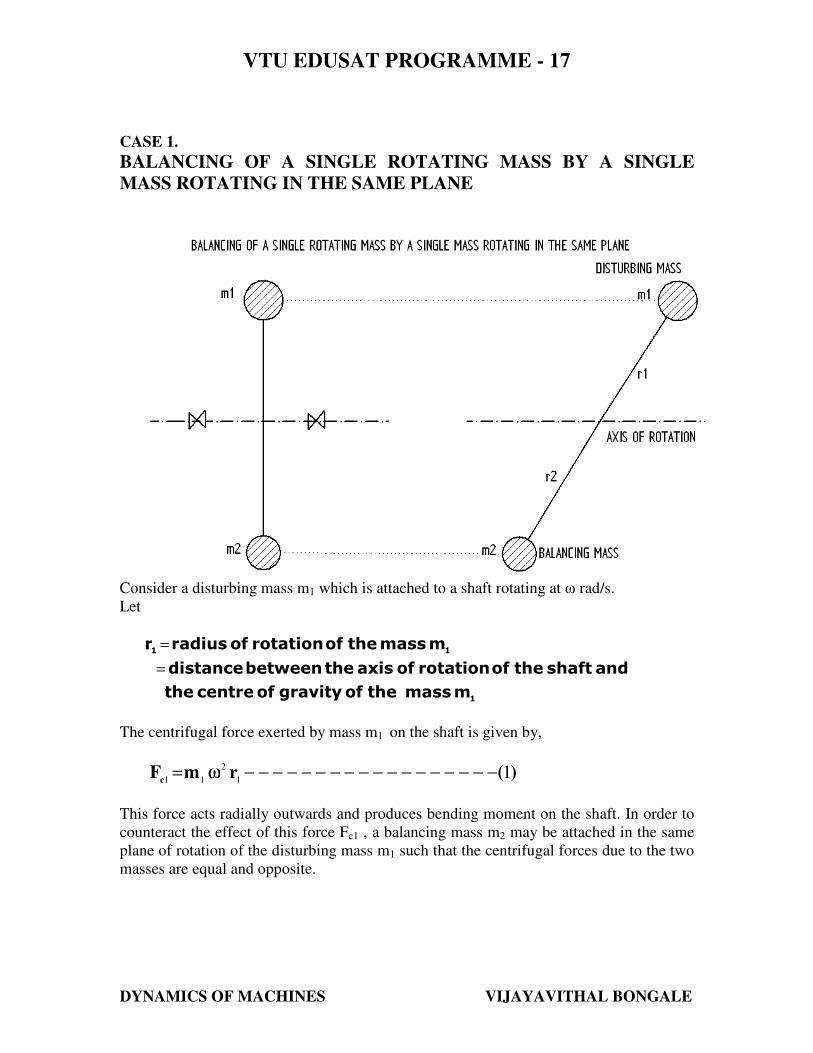
CASE 1.
BALANCING OF A SINGLE ROTATING MASS BY A SINGLE
MASS ROTATING IN THE SAME PLANE
Consider a disturbing mass m1 which is attached to a shaft rotating at ω rad/s.
Let
1
11
m mass the of gravity of centre the
and shaft the of rotation of axis the between distance
m mass the of rotation of radiusr
=
=
The centrifugal force exerted by mass m1 on the shaft is given by,
)(rmFc
11
2
11−−−−−−−−−−−−−−−−−−ω=
This force acts radially outwards and produces bending moment on the shaft. In order to
counteract the effect of this force Fc1 , a balancing mass m2 may be attached in the same
plane of rotation of the disturbing mass m1 such that the centrifugal forces due to the two
masses are equal and opposite.
VTU EDUSAT PROGRAMME - 17
DYNAMICS OF MACHINES VIJAYAVITHAL BONGALE
Let,
2
22
m mass the of gravity of centre the
and shaft the of rotation of axis the between distance
m mass the of rotation of radiusr
=
=
Therefore the centrifugal force due to mass m2 will be,
(2)rωmF2
2
2c2−−−−−−−−−−−−−−−−−−=
Equating equations (1) and (2), we get
(3)rmrmorrωmrωm
FF
22112
2
21
2
1
c2c1
−−−−−−−−−−−−−−−−==
=
The product 22
rm can be split up in any convenient way. As for as possible the radius
of rotation of mass m2 that is r2 is generally made large in order to reduce the balancing
mass m2.
CASE 2:
BALANCING OF A SINGLE ROTATING MASS BY TWO MASSES ROTATING
IN DIFFERENT PLANES.
There are two possibilities while attaching two balancing masses:
1. The plane of the disturbing mass may be in between the planes of the two
balancing masses.
2. The plane of the disturbing mass may be on the left or right side of two planes
containing the balancing masses.
In order to balance a single rotating mass by two masses rotating in different planes
which are parallel to the plane of rotation of the disturbing mass i) the net dynamic force
acting on the shaft must be equal to zero, i.e. the centre of the masses of the system must
lie on the axis of rotation and this is the condition for static balancing ii) the net couple
due to the dynamic forces acting on the shaft must be equal to zero, i.e. the algebraic sum
of the moments about any point in the plane must be zero. The conditions i) and ii)
together give dynamic balancing.
VTU EDUSAT PROGRAMME - 17
DYNAMICS OF MACHINES VIJAYAVITHAL BONGALE
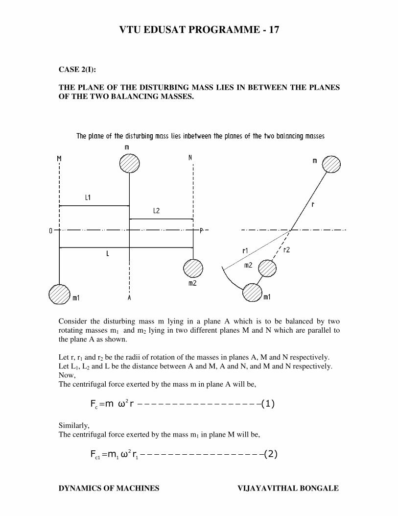
CASE 2(I):
THE PLANE OF THE DISTURBING MASS LIES IN BETWEEN THE PLANES
OF THE TWO BALANCING MASSES.
Consider the disturbing mass m lying in a plane A which is to be balanced by two
rotating masses m1 and m2 lying in two different planes M and N which are parallel to
the plane A as shown.
Let r, r1 and r2 be the radii of rotation of the masses in planes A, M and N respectively.
Let L1, L2 and L be the distance between A and M, A and N, and M and N respectively.
Now,
The centrifugal force exerted by the mass m in plane A will be,
(1)rωmF 2
c−−−−−−−−−−−−−−−−−−=
Similarly,
The centrifugal force exerted by the mass m1 in plane M will be,
(2)rωmF1
2
1c1−−−−−−−−−−−−−−−−−−=
VTU EDUSAT PROGRAMME - 17
DYNAMICS OF MACHINES VIJAYAVITHAL BONGALE
And the centrifugal force exerted by the mass m2 in plane N will be,
(3)rωmF2
2
2c2−−−−−−−−−−−−−−−−−−=
For the condition of static balancing,
(4)rmrmrmi.e.
rωmrωmrωmor
FFF
2211
2
2
21
2
1
2
c2c1c
−−−−−−−−−−−−−−−−+=
+=
+=
Now, to determine the magnitude of balancing force in the plane ‘M’ or the dynamic
force at the bearing ‘O’ of a shaft, take moments about ‘ P ’ which is the point of
intersection of the plane N and the axis of rotation.
Therefore,
(5)L
LrmrmorLrmLrm
,Therefore
LxrωmLxrωmor
LxFLxF
2
11211
2
2
1
2
1
2cc1
−−−−−−−−==
=
=
Similarly, in order to find the balancing force in plane ‘N’ or the dynamic force at the
bearing ‘P’ of a shaft, take moments about ‘ O ’ which is the point of intersection of the
plane M and the axis of rotation.
Therefore,
(6)L
LrmrmorLrmLrm
,Therefore
LxrωmLxrωmor
LxFLxF
1
22122
1
2
2
2
2
1cc2
−−−−−−−−==
=
=
For dynamic balancing equations (5) or (6) must be satisfied along with equation (4).
VTU EDUSAT PROGRAMME - 17
DYNAMICS OF MACHINES VIJAYAVITHAL BONGALE
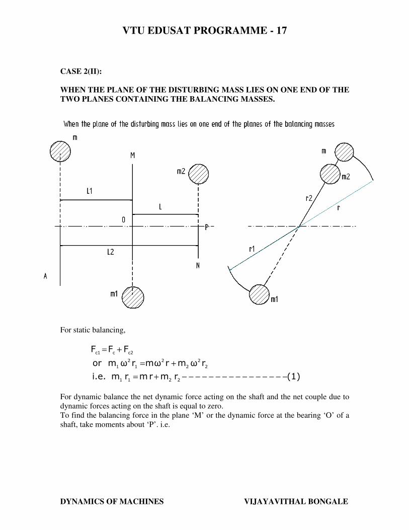
CASE 2(II):
WHEN THE PLANE OF THE DISTURBING MASS LIES ON ONE END OF THE
TWO PLANES CONTAINING THE BALANCING MASSES.
For static balancing,
(1)rmrmrmi.e.
rωmrωmrωmor
FFF
2211
2
2
2
2
1
2
1
c2cc1
−−−−−−−−−−−−−−−−+=
+=
+=
For dynamic balance the net dynamic force acting on the shaft and the net couple due to
dynamic forces acting on the shaft is equal to zero.
To find the balancing force in the plane ‘M’ or the dynamic force at the bearing ‘O’ of a
shaft, take moments about ‘P’. i.e.
VTU EDUSAT PROGRAMME - 17
DYNAMICS OF MACHINES VIJAYAVITHAL BONGALE
(2)L
LrmrmorLrmLrm
,Therefore
LxrωmLxrωmor
LxFLxF
2
11211
2
2
1
2
1
2cc1
−−−−−−−−==
=
=
Similarly, to find the balancing force in the plane ‘N’ , take moments about ‘O’, i.e.,
(3)L
LrmrmorLrmLrm
,Therefore
LxrωmLxrωmor
LxFLxF
1
22122
1
2
2
2
2
1cc2
−−−−−−−−==
=
=
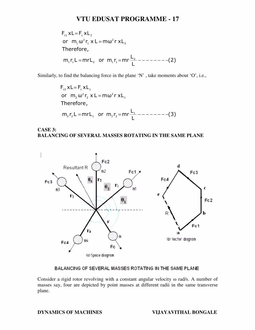
CASE 3:
BALANCING OF SEVERAL MASSES ROTATING IN THE SAME PLANE
Consider a rigid rotor revolving with a constant angular velocity ω rad/s. A number of
masses say, four are depicted by point masses at different radii in the same transverse
plane.
VTU EDUSAT PROGRAMME - 17
DYNAMICS OF MACHINES VIJAYAVITHAL BONGALE
If m1, m2, m3 and m4 are the masses revolving at radii r1, r2, r3 and r4 respectively in the
same plane.
The centrifugal forces exerted by each of the masses are Fc1, Fc2, Fc3 and Fc4 respectively.
Let F be the vector sum of these forces. i.e.
(1)rωmrωmrωmrωm
FFFFF
4
2
43
2
32
2
21
2
1
c4c3c2c1
−−−−−−−−−+++=
+++=
The rotor is said to be statically balanced if the vector sum F is zero. If the vector sum F
is not zero, i.e. the rotor is unbalanced, then introduce a counterweight ( balance weight)
of mass ‘m’ at radius ‘r’ to balance the rotor so that,
(3)0rmrmrmrmrm
or
(2)0rωmrωmrωmrωmrωm
44332211
2
4
2
43
2
32
2
21
2
1
−−−−−−−−−−−−−−−−=++++
−−−−−−−−−=++++
The magnitude of either ‘m’ or ‘r’ may be selected and the other can be calculated.
In general, if ∑ iirm is the vector sum of
11rm ,
22rm ,
33rm ,
44rm etc, then,
∑ −−−−−−−−=+ (4)0rmrmii
The above equation can be solved either analytically or graphically.
1. Analytical Method:
Procedure:
Step 1: Find out the centrifugal force or the product of mass and its radius of rotation
exerted by each of masses on the rotating shaft, since 2ω is same for each mass,
therefore the magnitude of the centrifugal force for each mass is proportional to the
product of the respective mass and its radius of rotation.
Step 2: Resolve these forces into their horizontal and vertical components and find their
sums. i.e.,
−−−−−−−−+++==∑
=333222111
n
1iiii
θcosrmθcosrmθcosrmθcosrm
componentshorizontaltheofSum
−−−−−−−−+++==∑
=333222111
n
1iiii
θsinrmθsinrmθsinrmθsinrm
componentsverticaltheofSum
VTU EDUSAT PROGRAMME - 17
DYNAMICS OF MACHINES VIJAYAVITHAL BONGALE
Step 3: Determine the magnitude of the resultant centrifugal force
2n
1iiii
2n
1iiii
θsinrmθcosrmR
+
= ∑∑
==
Step 4: If θ is the angle, which resultant force makes with the horizontal, then
∑
∑
=
==n
1iiii
n
1iiii
θcosrm
θsinrmθtan
Step 5: The balancing force is then equal to the resultant force, but in opposite direction.
Step 6: Now find out the magnitude of the balancing mass, such that
rmR=
Where, m = balancing mass and r = its radius of rotation
2. Graphical Method:
Step 1:
Draw the space diagram with the positions of the several masses, as shown.
Step 2:
Find out the centrifugal forces or product of the mass and radius of rotation exerted by
each mass.
Step 3:
Now draw the vector diagram with the obtained centrifugal forces or product of the
masses and radii of rotation. To draw vector diagram take a suitable scale.
Let ab, bc, cd, de represents the forces Fc1, Fc2, Fc3 and Fc4 on the vector diagram.
Draw ‘ab’ parallel to force Fc1 of the space diagram, at ‘b’ draw a line parallel to force
Fc2. Similarly draw lines cd, de parallel to Fc3 and Fc4 respectively.
Step 4:
As per polygon law of forces, the closing side ‘ae’ represents the resultant force in
magnitude and direction as shown in vector diagram.
Step 5:
The balancing force is then , equal and opposite to the resultant force.
Step 6:
VTU EDUSAT PROGRAMME - 17
DYNAMICS OF MACHINES VIJAYAVITHAL BONGALE
Determine the magnitude of the balancing mass ( m ) at a given radius of rotation ( r ),
such that,
44332211
2
c
rmandrm,rm,rmofresultantrm
or
rωmF
=
=
CASE 4:
BALANCING OF SEVERAL MASSES ROTATING IN DIFFERENT PLANES
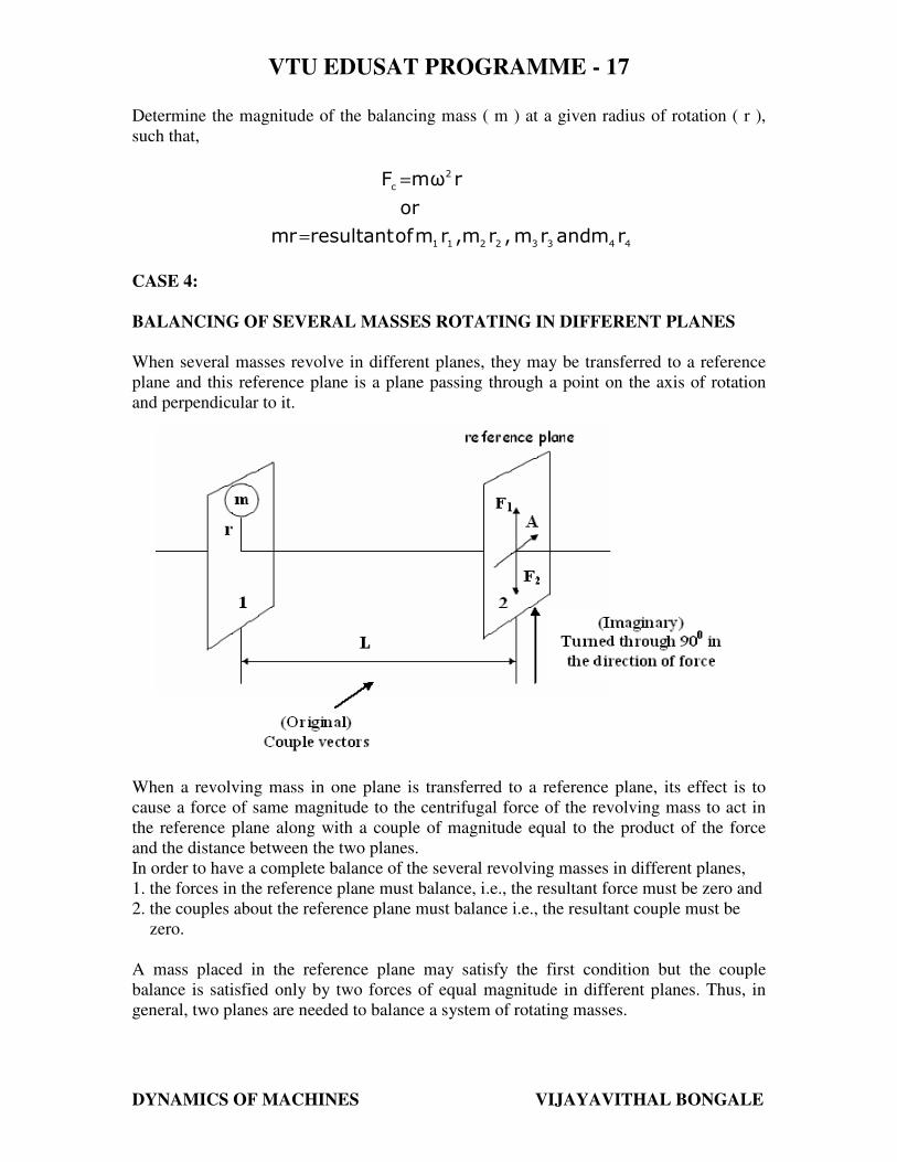
When several masses revolve in different planes, they may be transferred to a reference
plane and this reference plane is a plane passing through a point on the axis of rotation
and perpendicular to it.
When a revolving mass in one plane is transferred to a reference plane, its effect is to
cause a force of same magnitude to the centrifugal force of the revolving mass to act in
the reference plane along with a couple of magnitude equal to the product of the force
and the distance between the two planes.
In order to have a complete balance of the several revolving masses in different planes,
1. the forces in the reference plane must balance, i.e., the resultant force must be zero and
2. the couples about the reference plane must balance i.e., the resultant couple must be
zero.
A mass placed in the reference plane may satisfy the first condition but the couple
balance is satisfied only by two forces of equal magnitude in different planes. Thus, in
general, two planes are needed to balance a system of rotating masses.
m
VTU EDUSAT PROGRAMME - 17
DYNAMICS OF MACHINES VIJAYAVITHAL BONGALE
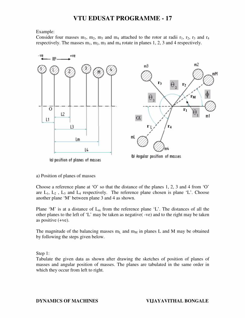
Example:
Consider four masses m1, m2, m3 and m4 attached to the rotor at radii r1, r2, r3 and r4
respectively. The masses m1, m2, m3 and m4 rotate in planes 1, 2, 3 and 4 respectively.
a) Position of planes of masses
Choose a reference plane at ‘O’ so that the distance of the planes 1, 2, 3 and 4 from ‘O’
are L1, L2 , L3 and L4 respectively. The reference plane chosen is plane ‘L’. Choose
another plane ‘M’ between plane 3 and 4 as shown.
Plane ‘M’ is at a distance of Lm from the reference plane ‘L’. The distances of all the
other planes to the left of ‘L’ may be taken as negative( -ve) and to the right may be taken
as positive (+ve).
The magnitude of the balancing masses mL and mM in planes L and M may be obtained
by following the steps given below.
Step 1:
Tabulate the given data as shown after drawing the sketches of position of planes of
masses and angular position of masses. The planes are tabulated in the same order in
which they occur from left to right.
VTU EDUSAT PROGRAMME - 17
DYNAMICS OF MACHINES VIJAYAVITHAL BONGALE
Plane
1
Mass (m)
2
Radius (r)
3
Centrifugal
force/ω2
(m r)
4
Distance
from Ref.
plane ‘L’ (L)
5
Couple/ ω2
(m r L)
6
1 m1 r1 m1 r1 - L1 - m1 r1 L1
L mL rL mL rL 0 0
2 m2 r2 m2 r2 L2 m2 r2 L2
3 m3 r3 m3 r3 L3 m3 r3 L3
M mM rM mM rM LM mM rM LM
4 m4 r4 m4 r4 L4 m4 r4 L4
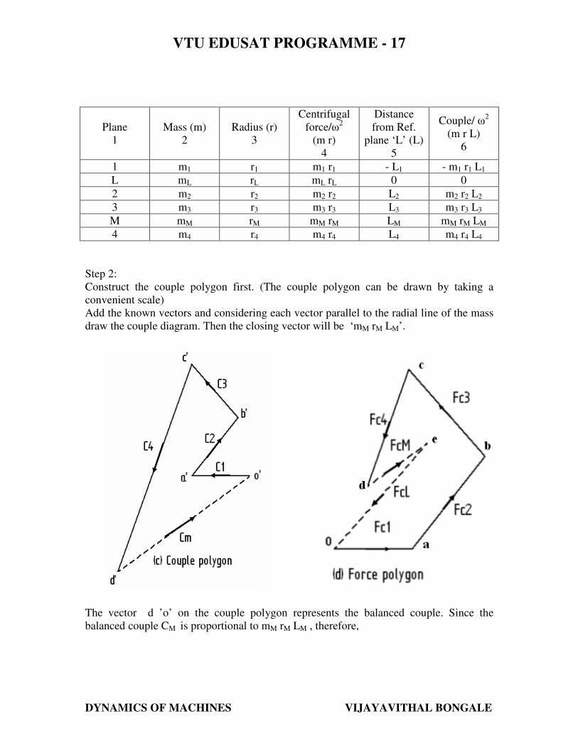
Step 2:
Construct the couple polygon first. (The couple polygon can be drawn by taking a
convenient scale)
Add the known vectors and considering each vector parallel to the radial line of the mass
draw the couple diagram. Then the closing vector will be ‘mM rM LM’.
The vector d ’o’ on the couple polygon represents the balanced couple. Since the
balanced couple CM is proportional to mM rM LM , therefore,
VTU EDUSAT PROGRAMME - 17
DYNAMICS OF MACHINES VIJAYAVITHAL BONGALE
MM
''
M
''
MMMM
L r
odvectormor
odvectorL r mC
=
==
From this the value of mM in the plane M can be determined and the angle of inclination
φ of this mass may be measured from figure (b).
Step 3:
Now draw the force polygon (The force polygon can be drawn by taking a convenient
scale) by adding the known vectors along with ‘mM rM’. The closing vector will be ‘mL
rL’. This represents the balanced force. Since the balanced force is proportional to ‘mL rL’
,
L
L
LL
r
eovectormor
eovector r m
=
=
From this the balancing mass mL can be obtained in plane ‘L’ and the angle of
inclination of this mass with the horizontal may be measured from figure (b).
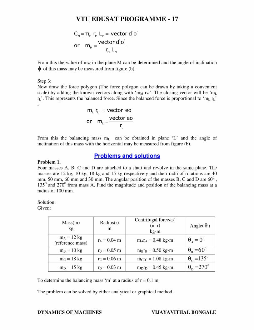
Problems and solutions Problem 1.
Four masses A, B, C and D are attached to a shaft and revolve in the same plane. The
masses are 12 kg, 10 kg, 18 kg and 15 kg respectively and their radii of rotations are 40
mm, 50 mm, 60 mm and 30 mm. The angular position of the masses B, C and D are 600 ,
1350 and 270
0 from mass A. Find the magnitude and position of the balancing mass at a
radius of 100 mm.
Solution:
Given:
Mass(m)
kg
Radius(r)
m
Centrifugal force/ω2
(m r)
kg-m Angle( θ )
mA = 12 kg
(reference mass) rA = 0.04 m mArA = 0.48 kg-m
00=θ
A
mB = 10 kg rB = 0.05 m mBrB = 0.50 kg-m 0
06=θB
mC = 18 kg rC = 0.06 m mCrC = 1.08 kg-m 0
135=θC
mD = 15 kg rD = 0.03 m mDrD = 0.45 kg-m 0
270=θD
To determine the balancing mass ‘m’ at a radius of r = 0.1 m.
The problem can be solved by either analytical or graphical method.
VTU EDUSAT PROGRAMME - 17
DYNAMICS OF MACHINES VIJAYAVITHAL BONGALE
Analytical Method:
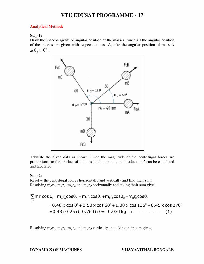
Step 1:
Draw the space diagram or angular position of the masses. Since all the angular position
of the masses are given with respect to mass A, take the angular position of mass A
as0
0=θA
.
Tabulate the given data as shown. Since the magnitude of the centrifugal forces are
proportional to the product of the mass and its radius, the product ‘mr’ can be calculated
and tabulated.
Step 2:
Resolve the centrifugal forces horizontally and vertically and find their sum.
Resolving mArA, mBrB, mCrC and mDrD horizontally and taking their sum gives,
(1)mkg0.03400.764)(0.250.48
270cosx0.45135cosx1.0860cosx0.500cosx0.48
cosθrmcosθrmcosθrmcosθrmθcosrm
0000
DDDCCCBBBAAA
n
1iiii
−−−−−−−−−−−=+−++=
+++=
+++=∑=
Resolving mArA, mBrB, mCrC and mDrD vertically and taking their sum gives,
VTU EDUSAT PROGRAMME - 17
DYNAMICS OF MACHINES VIJAYAVITHAL BONGALE
(2)mkg0.7470.45)(0.7640.4330
270sinx0.45135sinx1.0860sinx0.500sinx0.48
sinθrmsinθrmsinθrmθsinrmθsinrm
0000
DDDCCCBBBAAA
n
1iiii
−−−−−−−−−−=−+++=
+++=
+++=∑=
Step 3:
Determine the magnitude of the resultant centrifugal force
( ) ( ) mkg0.7480.7470.034
θsinrmθcosrmR
22
2n
1iiii
2n
1iiii
−=+−=
+
= ∑∑
==
Step 4:
The balancing force is then equal to the resultant force, but in opposite direction. Now
find out the magnitude of the balancing mass, such that
Anskg7.48
0.1
0.748
r
RmTherefore,
mkg0.748rmR
===
−==
Where, m = balancing mass and r = its radius of rotation
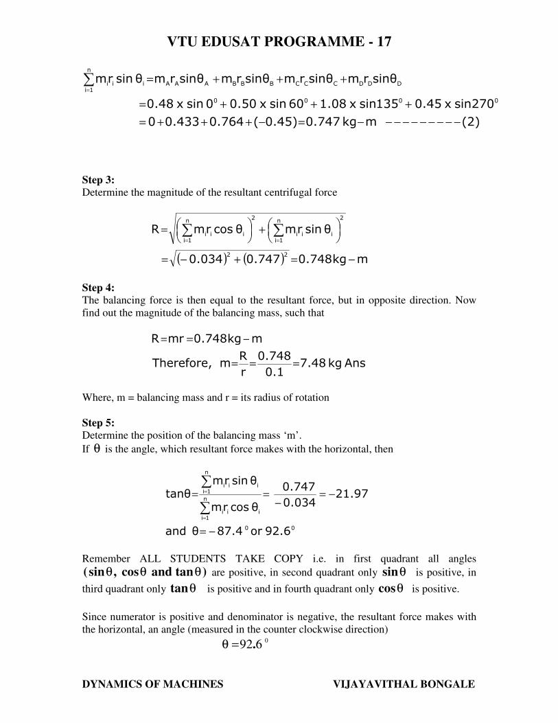
Step 5:
Determine the position of the balancing mass ‘m’.
If θ is the angle, which resultant force makes with the horizontal, then
00
n
1iiii
n
1iiii
92.6or87.4θand
21.970.034
0.747
θcosrm
θsinrmθtan
−=
−=−
==
∑
∑
=
=
Remember ALL STUDENTS TAKE COPY i.e. in first quadrant all angles
)tanandcos,sin( θθθ are positive, in second quadrant only θsin is positive, in
third quadrant only θtan is positive and in fourth quadrant only θcos is positive.
Since numerator is positive and denominator is negative, the resultant force makes with
the horizontal, an angle (measured in the counter clockwise direction)
0
692.=θ
VTU EDUSAT PROGRAMME - 17
DYNAMICS OF MACHINES VIJAYAVITHAL BONGALE
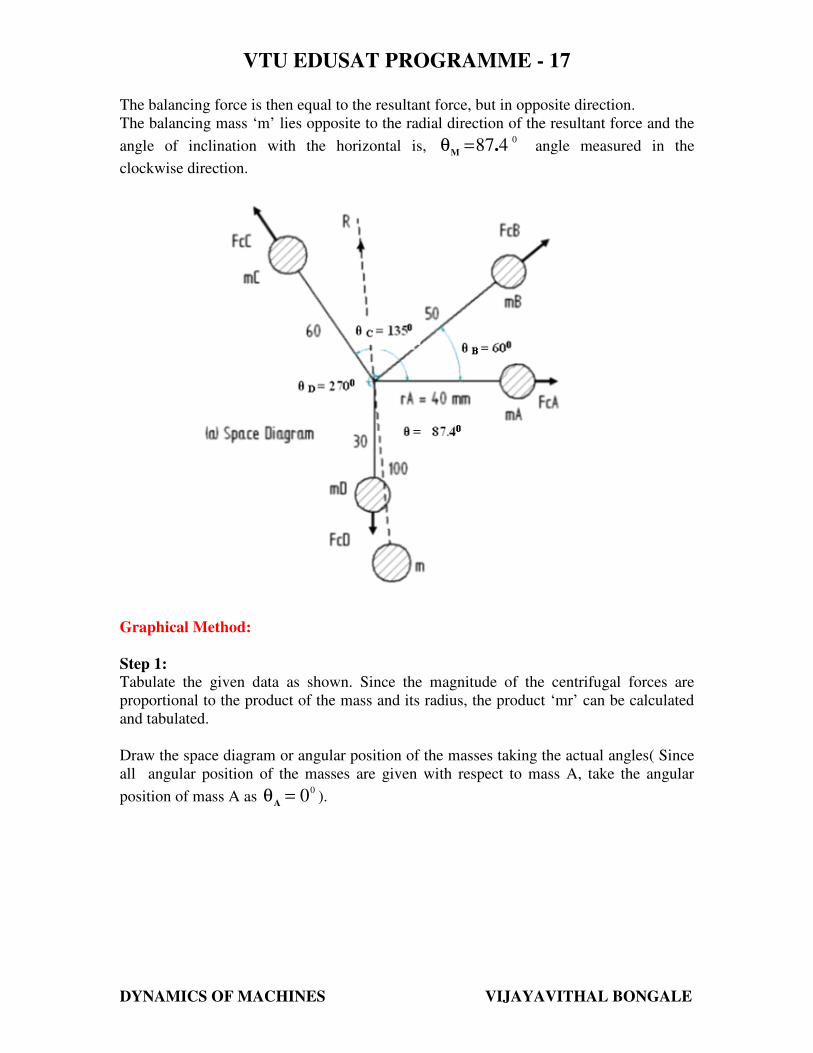
The balancing force is then equal to the resultant force, but in opposite direction.
The balancing mass ‘m’ lies opposite to the radial direction of the resultant force and the
angle of inclination with the horizontal is,0
487.M
=θ angle measured in the
clockwise direction.
Graphical Method:
Step 1:
Tabulate the given data as shown. Since the magnitude of the centrifugal forces are
proportional to the product of the mass and its radius, the product ‘mr’ can be calculated
and tabulated.
Draw the space diagram or angular position of the masses taking the actual angles( Since
all angular position of the masses are given with respect to mass A, take the angular
position of mass A as 0
0=θA
).
VTU EDUSAT PROGRAMME - 17
DYNAMICS OF MACHINES VIJAYAVITHAL BONGALE
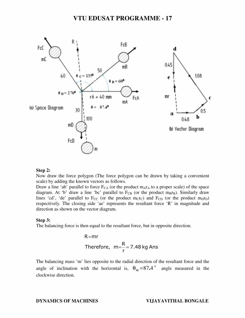
Step 2:
Now draw the force polygon (The force polygon can be drawn by taking a convenient
scale) by adding the known vectors as follows.
Draw a line ‘ab’ parallel to force FCA (or the product mArA to a proper scale) of the space
diagram. At ‘b’ draw a line ‘bc’ parallel to FCB (or the product mBrB). Similarly draw
lines ‘cd’, ‘de’ parallel to FCC (or the product mCrC) and FCD (or the product mDrD)
respectively. The closing side ‘ae’ represents the resultant force ‘R’ in magnitude and
direction as shown on the vector diagram.
Step 3:
The balancing force is then equal to the resultant force, but in opposite direction.
Anskg7.48
r
RmTherefore,
rmR
==
=
The balancing mass ‘m’ lies opposite to the radial direction of the resultant force and the
angle of inclination with the horizontal is,0
487.M
=θ angle measured in the
clockwise direction.
VTU EDUSAT PROGRAMME - 17
DYNAMICS OF MACHINES VIJAYAVITHAL BONGALE
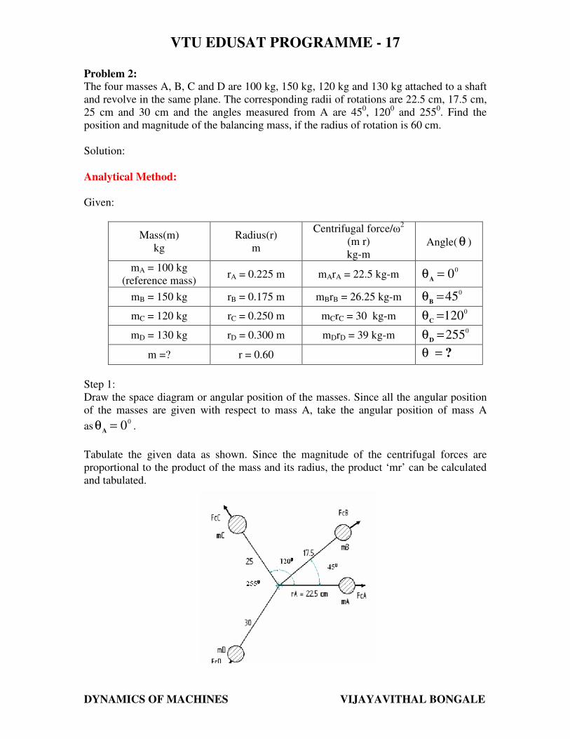
Problem 2:
The four masses A, B, C and D are 100 kg, 150 kg, 120 kg and 130 kg attached to a shaft
and revolve in the same plane. The corresponding radii of rotations are 22.5 cm, 17.5 cm,
25 cm and 30 cm and the angles measured from A are 450, 120
0 and 255
0. Find the
position and magnitude of the balancing mass, if the radius of rotation is 60 cm.
Solution:
Analytical Method:
Given:
Mass(m)
kg
Radius(r)
m
Centrifugal force/ω2
(m r)
kg-m Angle( θ )
mA = 100 kg
(reference mass) rA = 0.225 m mArA = 22.5 kg-m
00=θ
A
mB = 150 kg rB = 0.175 m mBrB = 26.25 kg-m 0
45=θB
mC = 120 kg rC = 0.250 m mCrC = 30 kg-m 0
120=θC
mD = 130 kg rD = 0.300 m mDrD = 39 kg-m 0
255=θD
m =? r = 0.60 ?=θ
Step 1:
Draw the space diagram or angular position of the masses. Since all the angular position
of the masses are given with respect to mass A, take the angular position of mass A
as0
0=θA
.
Tabulate the given data as shown. Since the magnitude of the centrifugal forces are
proportional to the product of the mass and its radius, the product ‘mr’ can be calculated
and tabulated.
VTU EDUSAT PROGRAMME - 17
DYNAMICS OF MACHINES VIJAYAVITHAL BONGALE
Step 2:
Resolve the centrifugal forces horizontally and vertically and find their sum.
Resolving mArA, mBrB, mCrC and mDrD horizontally and taking their sum gives,
(1)mkg15.9710.1)(15)(18.5622.5
255cosx39120cosx3045cosx26.250cosx22.5
cosθrmcosθrmcosθrmcosθrmθcosrm
0000
DDDCCCBBBAAA
n
1iiii
−−−−−−−−−−=−+−++=
+++=
+++=∑=
Resolving mArA, mBrB, mCrC and mDrD vertically and taking their sum gives,
(2)mkg6.8737.67)(25.9818.560
255sinx39120sinx3045sinx26.250sinx22.5
sinθrmsinθrmsinθrmθsinrmθsinrm
0000
DDDCCCBBBAAA
n
1iiii
−−−−−−−−−−=−+++=
+++=
+++=∑=
Step 3:
Determine the magnitude of the resultant centrifugal force
( ) ( ) mkg17.396.8715.97
θsinrmθcosrmR
22
2n
1iiii
2n
1iiii
−=+=
+
= ∑∑
==
Step 4:
The balancing force is then equal to the resultant force, but in opposite direction. Now
find out the magnitude of the balancing mass, such that
Anskg28.98
0.60
17.39
r
RmTherefore,
mkg17.39rmR
===
−==
Where, m = balancing mass and r = its radius of rotation
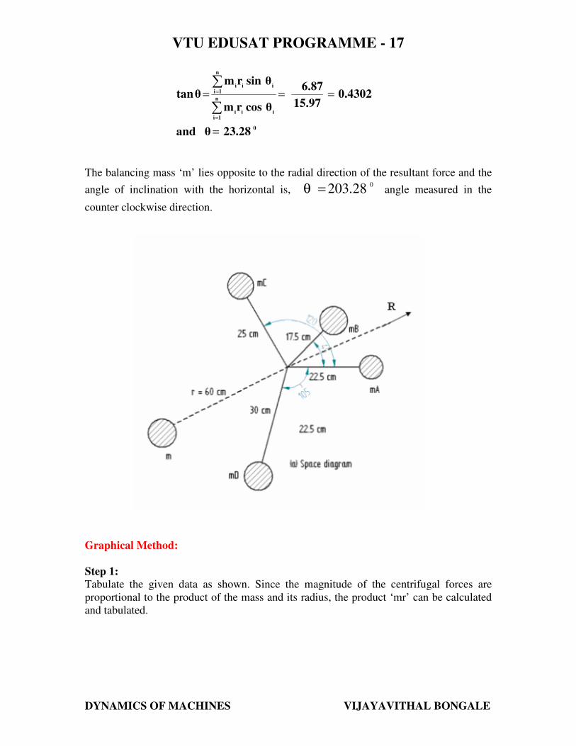
Step 5:
Determine the position of the balancing mass ‘m’.
If θ is the angle, which resultant force makes with the horizontal, then
VTU EDUSAT PROGRAMME - 17
DYNAMICS OF MACHINES VIJAYAVITHAL BONGALE
0
n
1iiii
n
1iiii
23.28θand
0.430215.97
6.87
θcosrm
θsinrmθtan
=
===
∑
∑
=
=
The balancing mass ‘m’ lies opposite to the radial direction of the resultant force and the
angle of inclination with the horizontal is,028.203=θ angle measured in the
counter clockwise direction.
Graphical Method:
Step 1:
Tabulate the given data as shown. Since the magnitude of the centrifugal forces are
proportional to the product of the mass and its radius, the product ‘mr’ can be calculated
and tabulated.

VTU EDUSAT PROGRAMME - 17
DYNAMICS OF MACHINES VIJAYAVITHAL BONGALE
Step 2:
Draw the space diagram or angular position of the masses taking the actual angles (Since
all angular position of the masses are given with respect to mass A, take the angular
position of mass A as0
0=θA
).
Step 3:
Now draw the force polygon (The force polygon can be drawn by taking a convenient
scale) by adding the known vectors as follows.
Draw a line ‘ab’ parallel to force FCA (or the product mArA to a proper scale) of the space
diagram. At ‘b’ draw a line ‘bc’ parallel to FCB (or the product mBrB). Similarly draw
lines ‘cd’, ‘de’ parallel to FCC (or the product mCrC) and FCD (or the product mDrD)
respectively. The closing side ‘ae’ represents the resultant force ‘R’ in magnitude and
direction as shown on the vector diagram.
Step 4:
The balancing force is then equal to the resultant force, but in opposite direction.
Anskg29
r
RmTherefore,
rmR
==
=
The balancing mass ‘m’ lies opposite to the radial direction of the resultant force and the
angle of inclination with the horizontal is,0203=θ angle measured in the counter
clockwise direction.
VTU EDUSAT PROGRAMME - 17
DYNAMICS OF MACHINES VIJAYAVITHAL BONGALE
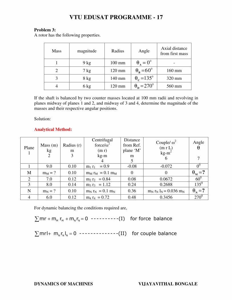
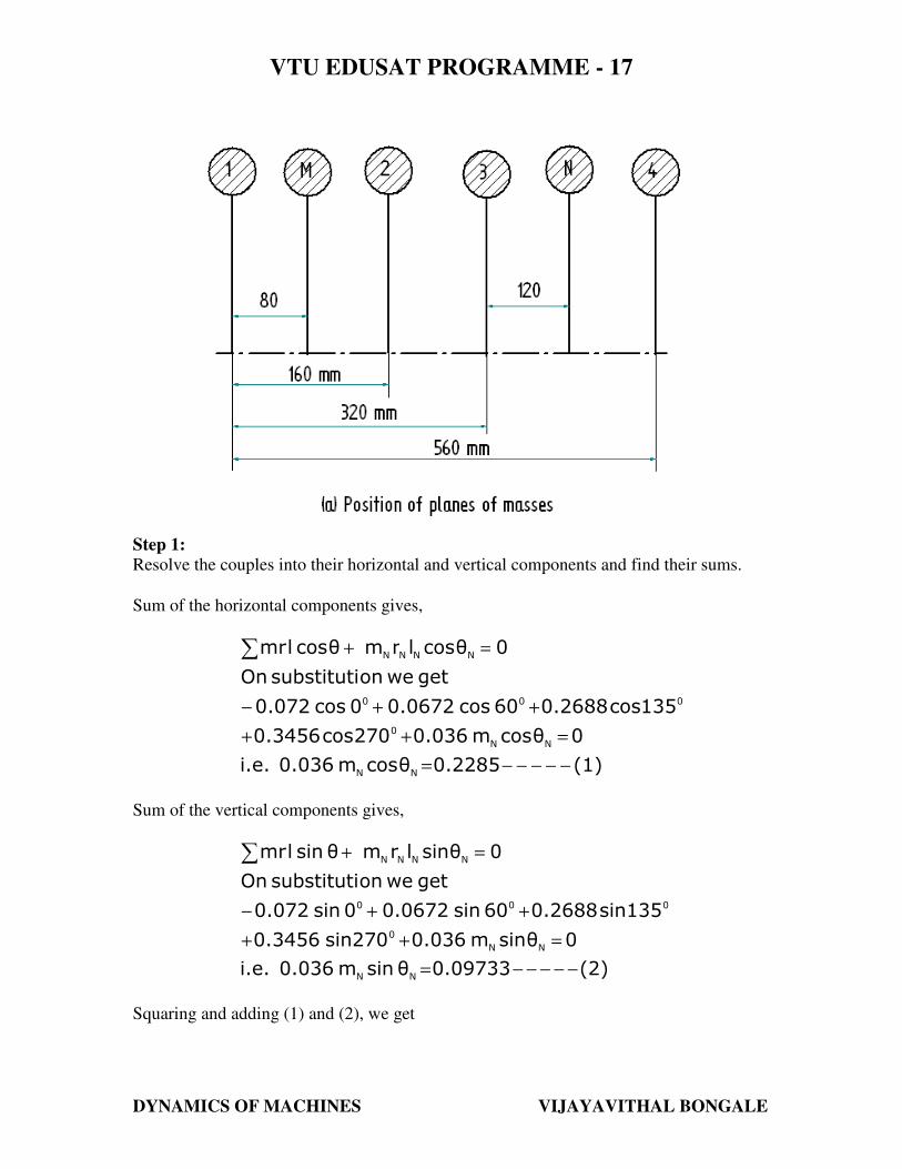
Problem 3:
A rotor has the following properties.
Mass
magnitude
Radius
Angle Axial distance
from first mass
1 9 kg 100 mm 0
0=θA
-
2 7 kg 120 mm 0
06=θB
160 mm
3 8 kg 140 mm 0
135=θC
320 mm
4 6 kg 120 mm 0
270=θD
560 mm
If the shaft is balanced by two counter masses located at 100 mm radii and revolving in
planes midway of planes 1 and 2, and midway of 3 and 4, determine the magnitude of the
masses and their respective angular positions.
Solution:
Analytical Method:
Plane
1
Mass (m)
kg
2
Radius (r)
m
3
Centrifugal
force/ω2
(m r)
kg-m
4
Distance
from Ref.
plane ‘M’
m
5
Couple/ ω2
(m r L)
kg-m2
6
Angle
θ
7
1 9.0 0.10 m1 r1 = 0.9 -0.08 -0.072 00
M mM = ? 0.10 mM rM = 0.1 mM 0 0 ?M
=θ
2 7.0 0.12 m2 r2 = 0.84 0.08 0.0672 600
3 8.0 0.14 m3 r3 = 1.12 0.24 0.2688 1350
N mN = ? 0.10 mN rN = 0.1 mN 0.36 mN rN lN = 0.036 mN ?N
=θ
4 6.0 0.12 m4 r4 = 0.72 0.48 0.3456 2700
For dynamic balancing the conditions required are,
∑
∑
=+
=++
balance couplefor -(II)------------- 0 lrmlmr
balance forcefor -(I)--------- 0 rm r mmr
NNN
NNMM
VTU EDUSAT PROGRAMME - 17
DYNAMICS OF MACHINES VIJAYAVITHAL BONGALE
Step 1:
Resolve the couples into their horizontal and vertical components and find their sums.
Sum of the horizontal components gives,
(1)0.2285θcosm0.036i.e.
0θcosm0.036270cos0.3456
135cos0.268860cos0.06720cos0.072
getweonsubstitutiOn
0 θcoslrmθcoslmr
NN
NN
0
000
NNNN
−−−−−=
=++
++−
=+∑
Sum of the vertical components gives,
(2)0.09733θsinm0.036i.e.
0θsinm0.036270sin0.3456
sin1350.268860sin0.06720sin0.072
getweonsubstitutiOn
0 θsinlrmθsinlmr
NN
NN
0
000
NNNN
−−−−−=
=++
++−
=+∑
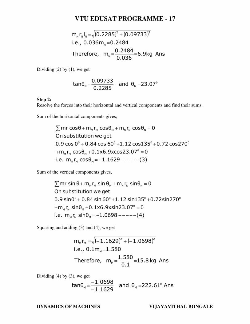
Squaring and adding (1) and (2), we get
VTU EDUSAT PROGRAMME - 17
DYNAMICS OF MACHINES VIJAYAVITHAL BONGALE
( ) ( )
Anskg6.90.036
0.2484mTherefore,
0.2484m0.036i.e.,
0.097330.2285lrm
N
N
22
NNN
==
=
+=
Dividing (2) by (1), we get
0
NN23.07θand
0.2285
0.09733θtan ==
Step 2:
Resolve the forces into their horizontal and vertical components and find their sums.
Sum of the horizontal components gives,
(3)1.1629θcosrmi.e.
023.07s0.1x6.9xcoθcosrm
270cos0.72135cos1.1260cos0.840cos0.9
getweonsubstitutiOn
0 θcosrmθcosrmθcosmr
MMM
0
MMM
0000
NNNMMM
−−−−−−=
=++
+++
=++∑
Sum of the vertical components gives,
(4)1.0698θsinrmi.e.
023.07n0.1x6.9xsiθsinrm
270sin0.72135sin1.1260sin0.840sin0.9
getweonsubstitutiOn
0 θsinrmθsinrmθsinmr
MMM
0
MMM
0000
NNNMMM
−−−−−−=
=++
+++
=++∑
Squaring and adding (3) and (4), we get
( ) ( )
Anskg15.80.1
1.580mTherefore,
1.580m0.1i.e.,
1.06981.1629rm
M
M
22
MM
==
=
−+−=
Dividing (4) by (3), we get
Ans222.61θand1.1629
1.0698θtan 0
MM=
−
−=
VTU EDUSAT PROGRAMME - 17
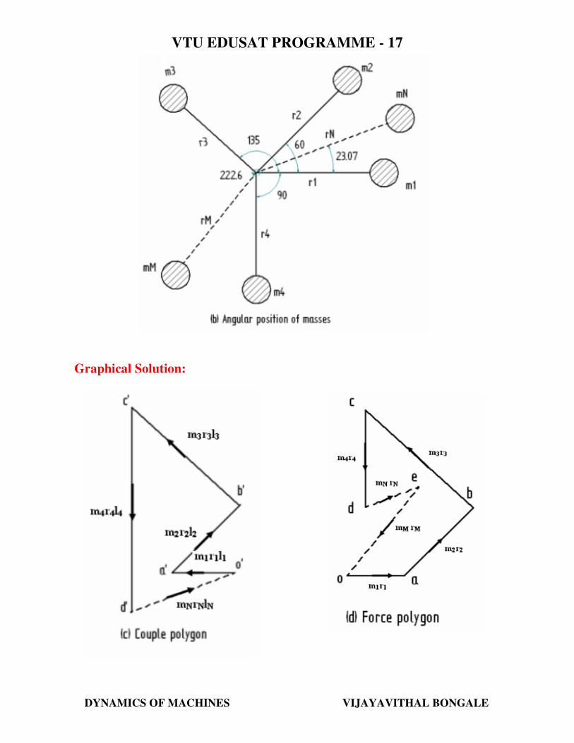
DYNAMICS OF MACHINES VIJAYAVITHAL BONGALE
Graphical Solution:
VTU EDUSAT PROGRAMME - 17
DYNAMICS OF MACHINES VIJAYAVITHAL BONGALE
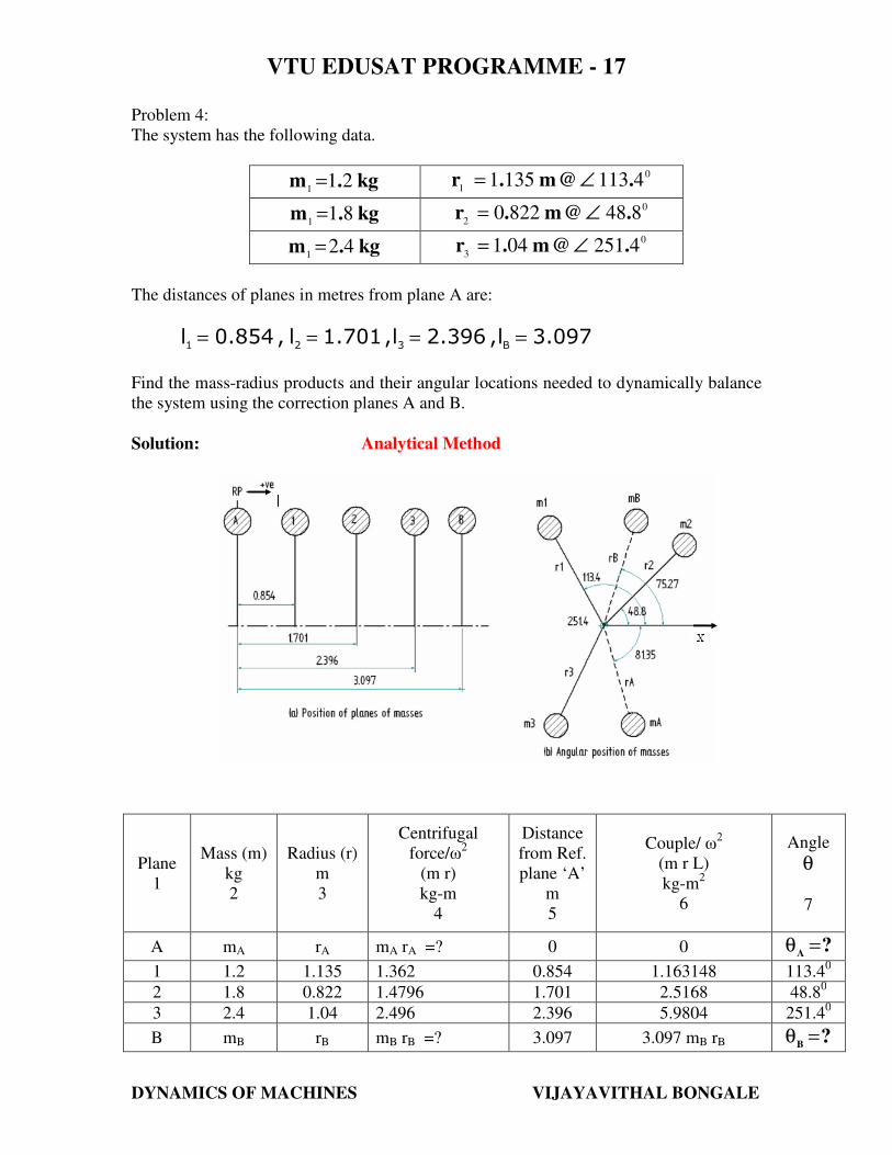
Problem 4:
The system has the following data.
kg.m 211=
0
141131351 [email protected] ∠=
kg.m 811=
0
28488220 [email protected] ∠=
kg.m 421=
0
34251041 [email protected] ∠=
The distances of planes in metres from plane A are:
3.097l,2.396l,1.701l,0.854lB321
====
Find the mass-radius products and their angular locations needed to dynamically balance
the system using the correction planes A and B.
Solution: Analytical Method
Plane
1
Mass (m)
kg
2
Radius (r)
m
3
Centrifugal
force/ω2
(m r)
kg-m
4
Distance
from Ref.
plane ‘A’
m
5
Couple/ ω2
(m r L)
kg-m2
6
Angle
θ
7
A mA rA mA rA =? 0 0 ?A
=θ
1 1.2 1.135 1.362 0.854 1.163148 113.40
2 1.8 0.822 1.4796 1.701 2.5168 48.80
3 2.4 1.04 2.496 2.396 5.9804 251.40
B mB rB mB rB =? 3.097 3.097 mB rB ?B
=θ
VTU EDUSAT PROGRAMME - 17
DYNAMICS OF MACHINES VIJAYAVITHAL BONGALE
Step 1:
Resolve the couples into their horizontal and vertical components and find their sums.
Sum of the horizontal components gives,
(1)3.097
0.71166θcosrmi.e.
0θcosrm3.097
251.4cos5.980448.8cos2.5168113.4cos1.163148
getweonsubstitutiOn
0 θcoslrmθcoslmr
BBB
BBB
000
BBBB
−−−−−=
=+
++
=+∑
Sum of the vertical components gives,
(2)3.097
2.7069θsinrmi.e.
0θsinrm3.097
251.4sin5.980448.8sin2.5168113.4sin1.163148
getweonsubstitutiOn
0 θsinlrmθsinlmr
BBB
BBB
000
BBBB
−−−−−=
=+
++
=+∑
Squaring and adding (1) and (2), we get
mkg0.9037
3.097
2.7069
3.097
0.71166rm
22
BB
−=
+
=
Dividing (2) by (1), we get
Ans75.27θand0.71166
2.7069θtan 0
BB==
Step 2:
Resolve the forces into their horizontal and vertical components and find their sums.
Sum of the horizontal components gives,
VTU EDUSAT PROGRAMME - 17
DYNAMICS OF MACHINES VIJAYAVITHAL BONGALE
(3)0.13266θcosrm
Therefore
075.27cos0.9037θcosrm
251.4cos2.49648.8cos1.4796113.4cos1.362
getweonsubstitutiOn
0 θcosrmθcosrmθcosmr
AAA
0
AAA
000
BBBAAA
−−−−−−−−−=
=++
++
=++∑
Sum of the vertical components gives,
(4)0.87162θsinrm
Therefore
075.27sin0.9037θsinrm
251.4sin2.49648.8sin1.4796113.4sin1.362
getweonsubstitutiOn
0 θsinrmθsinrmθsinmr
AAA
0
AAA
000
BBBAAA
−−−−−−−−−−=
=++
++
=++∑
Squaring and adding (3) and (4), we get
( ) ( )
mkg0.8817
0.871620.13266rm22
AA
−=
−+=
Dividing (4) by (3), we get
Ans81.35θand0.13266
0.87162θtan 0
AA−=
−=
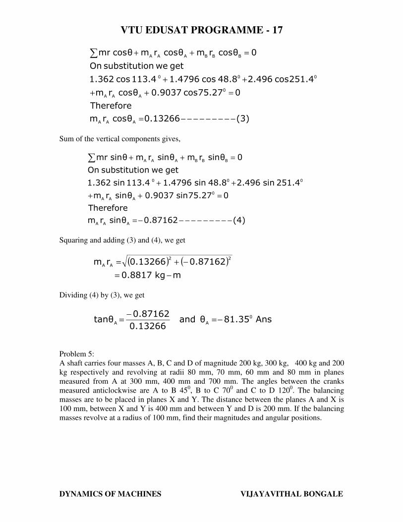
Problem 5:
A shaft carries four masses A, B, C and D of magnitude 200 kg, 300 kg, 400 kg and 200
kg respectively and revolving at radii 80 mm, 70 mm, 60 mm and 80 mm in planes
measured from A at 300 mm, 400 mm and 700 mm. The angles between the cranks
measured anticlockwise are A to B 450, B to C 70
0 and C to D 120
0. The balancing
masses are to be placed in planes X and Y. The distance between the planes A and X is
100 mm, between X and Y is 400 mm and between Y and D is 200 mm. If the balancing
masses revolve at a radius of 100 mm, find their magnitudes and angular positions.
VTU EDUSAT PROGRAMME - 17
DYNAMICS OF MACHINES VIJAYAVITHAL BONGALE
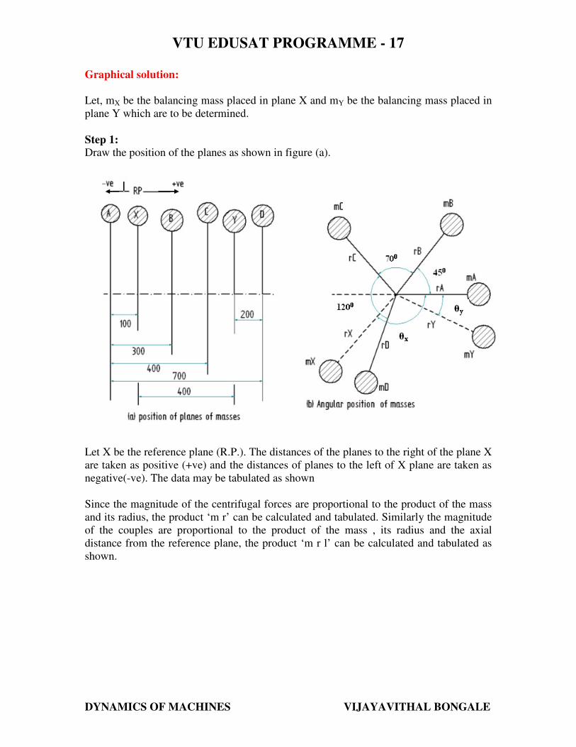
Graphical solution:
Let, mX be the balancing mass placed in plane X and mY be the balancing mass placed in
plane Y which are to be determined.
Step 1:
Draw the position of the planes as shown in figure (a).
Let X be the reference plane (R.P.). The distances of the planes to the right of the plane X
are taken as positive (+ve) and the distances of planes to the left of X plane are taken as
negative(-ve). The data may be tabulated as shown
Since the magnitude of the centrifugal forces are proportional to the product of the mass
and its radius, the product ‘m r’ can be calculated and tabulated. Similarly the magnitude
of the couples are proportional to the product of the mass , its radius and the axial
distance from the reference plane, the product ‘m r l’ can be calculated and tabulated as
shown.
VTU EDUSAT PROGRAMME - 17
DYNAMICS OF MACHINES VIJAYAVITHAL BONGALE
Plane
1
Mass
(m) kg
2
Radius (r)
m
3
Centrifugal
force/ω2
(m r)
kg-m
4
Distance
from Ref.
plane ‘X’
m
5
Couple/ ω2
(m r L)
kg-m2
6
Angle
θ
7
A 200 0.08 mA rA = 16 -0.10 -1.60 -
X mX =? 0.10 mX rX = 0.1 mX 0 0 ?X
=θ
B 300 0.07 mB rB = 21 0.20 4.20 A to B 450
C 400 0.06 mC rC = 24 0.30 7.20 B to C 700
Y mY =? 0.10 mY rY = 0.1 mY 0.40 mY rY lY = 0.04 mY ?Y
=θ
D 200 0.08 mD rD = 16 0.60 9.60 C to D 1200
Step 2:
Assuming the mass A as horizontal draw the sketch of angular position of masses as
shown in figure (b).
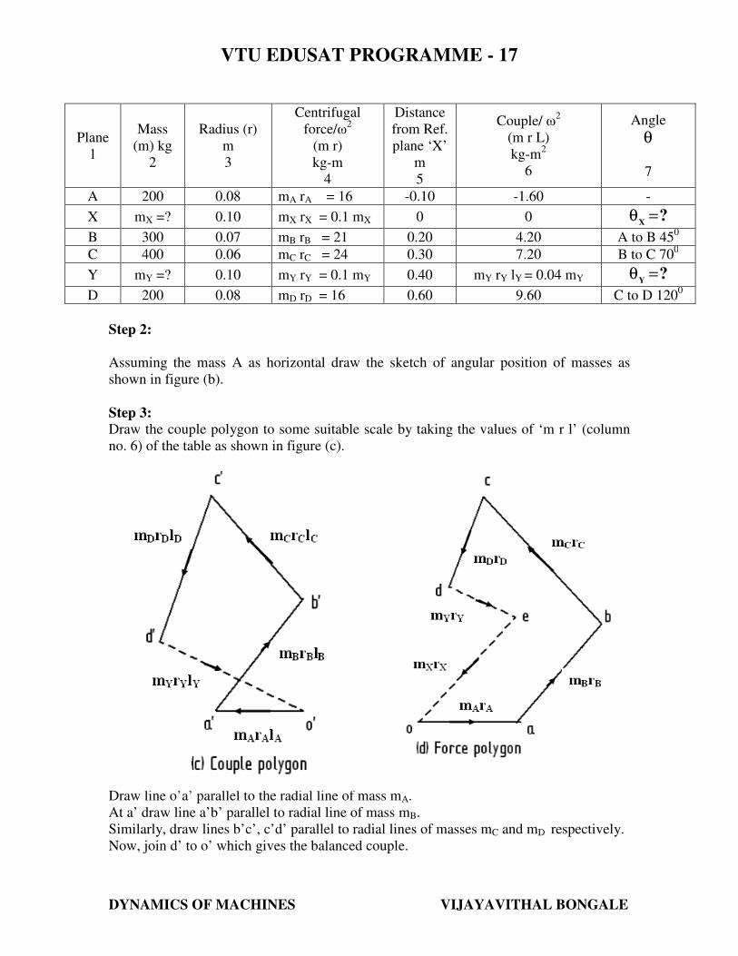
Step 3:
Draw the couple polygon to some suitable scale by taking the values of ‘m r l’ (column
no. 6) of the table as shown in figure (c).
Draw line o’a’ parallel to the radial line of mass mA.
At a’ draw line a’b’ parallel to radial line of mass mB.
Similarly, draw lines b’c’, c’d’ parallel to radial lines of masses mC and mD respectively.
Now, join d’ to o’ which gives the balanced couple.
VTU EDUSAT PROGRAMME - 17
DYNAMICS OF MACHINES VIJAYAVITHAL BONGALE
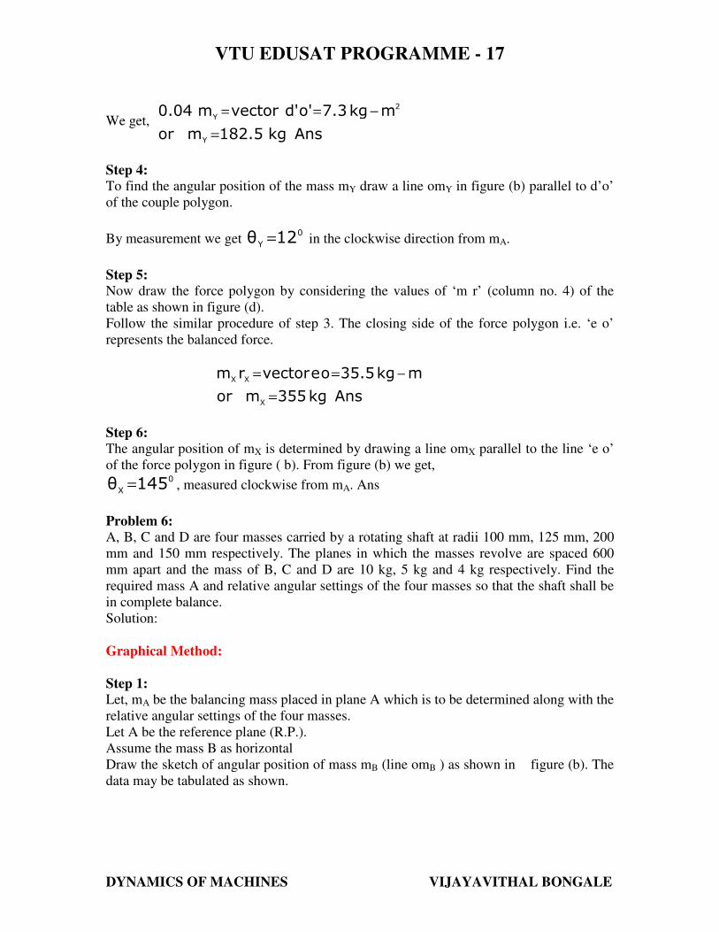
We get, Anskg182.5mor
mkg7.3o'd'vectorm0.04
Y
2
Y
=
−==
Step 4:
To find the angular position of the mass mY draw a line omY in figure (b) parallel to d’o’
of the couple polygon.
By measurement we get 0
Y12θ = in the clockwise direction from mA.
Step 5:
Now draw the force polygon by considering the values of ‘m r’ (column no. 4) of the
table as shown in figure (d).
Follow the similar procedure of step 3. The closing side of the force polygon i.e. ‘e o’
represents the balanced force.
Anskg355mor
mkg35.5oevectorrm
X
XX
=
−==
Step 6:
The angular position of mX is determined by drawing a line omX parallel to the line ‘e o’
of the force polygon in figure ( b). From figure (b) we get, 0
X145θ = , measured clockwise from mA. Ans
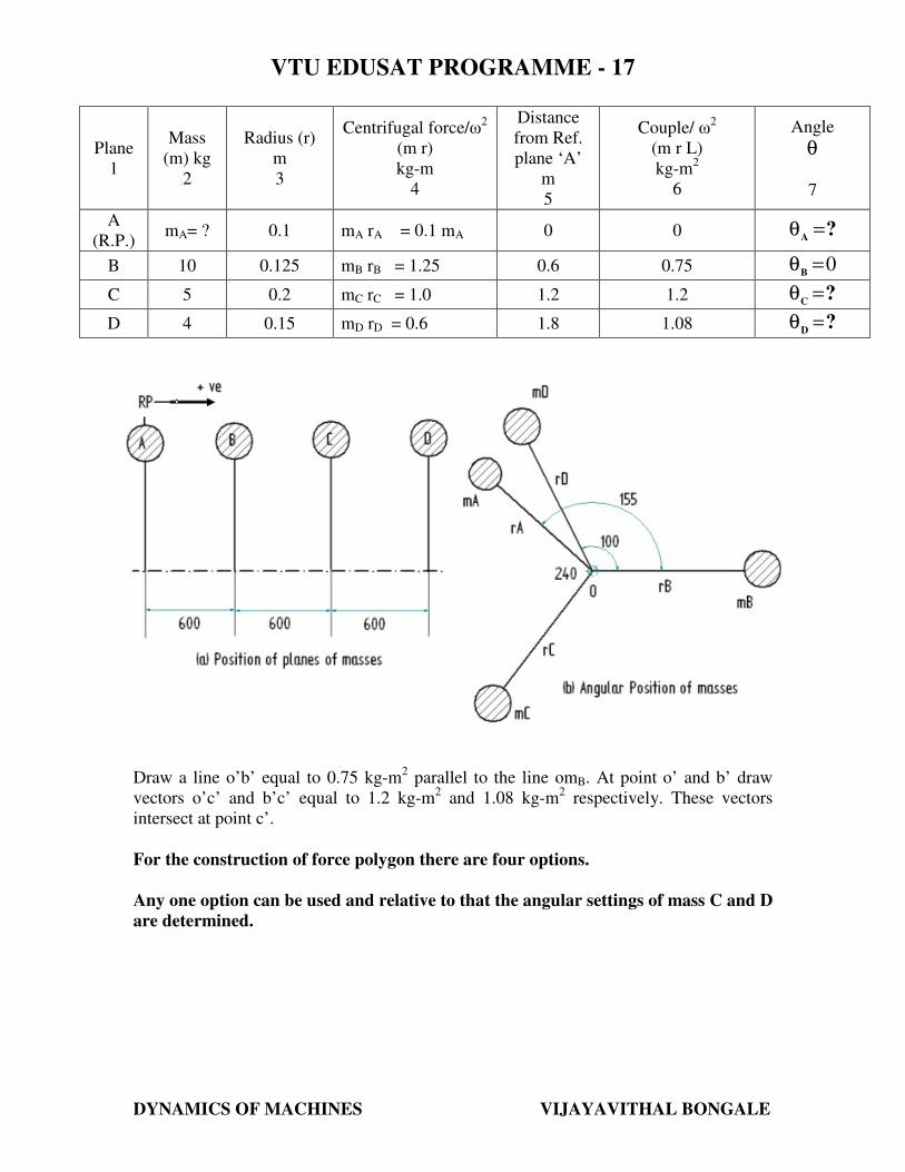
Problem 6:
A, B, C and D are four masses carried by a rotating shaft at radii 100 mm, 125 mm, 200
mm and 150 mm respectively. The planes in which the masses revolve are spaced 600
mm apart and the mass of B, C and D are 10 kg, 5 kg and 4 kg respectively. Find the
required mass A and relative angular settings of the four masses so that the shaft shall be
in complete balance.
Solution:
Graphical Method:
Step 1:
Let, mA be the balancing mass placed in plane A which is to be determined along with the
relative angular settings of the four masses.
Let A be the reference plane (R.P.).
Assume the mass B as horizontal
Draw the sketch of angular position of mass mB (line omB ) as shown in figure (b). The
data may be tabulated as shown.
VTU EDUSAT PROGRAMME - 17
DYNAMICS OF MACHINES VIJAYAVITHAL BONGALE
Plane
1
Mass
(m) kg
2
Radius (r)
m
3
Centrifugal force/ω2
(m r)
kg-m
4
Distance
from Ref.
plane ‘A’
m
5
Couple/ ω2
(m r L)
kg-m2
6
Angle
θ
7
A
(R.P.) mA= ? 0.1 mA rA = 0.1 mA 0 0 ?
A=θ
B 10 0.125 mB rB = 1.25 0.6 0.75 0=θB
C 5 0.2 mC rC = 1.0 1.2 1.2 ?C
=θ
D 4 0.15 mD rD = 0.6 1.8 1.08 ?D
=θ
Step 2:
To determine the angular settings of mass C and D the couple polygon is to be drawn first
as shown in fig (c). Take a convenient scale
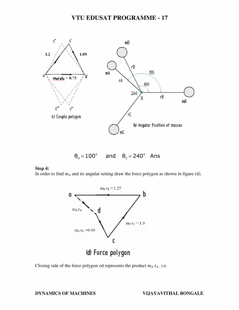
Draw a line o’b’ equal to 0.75 kg-m2 parallel to the line omB. At point o’ and b’ draw
vectors o’c’ and b’c’ equal to 1.2 kg-m2 and 1.08 kg-m
2 respectively. These vectors
intersect at point c’.
For the construction of force polygon there are four options.
Any one option can be used and relative to that the angular settings of mass C and D
are determined.
VTU EDUSAT PROGRAMME - 17
DYNAMICS OF MACHINES VIJAYAVITHAL BONGALE
Step 3:
Now in figure (b), draw lines omC and omD parallel to o’c’ and b’c’ respectively.
From measurement we get,
Ans240θand100θ 0
C
0
D==
Step 4:
In order to find mA and its angular setting draw the force polygon as shown in figure (d).
Closing side of the force polygon od represents the product mA rA . i.e.
VTU EDUSAT PROGRAMME - 17
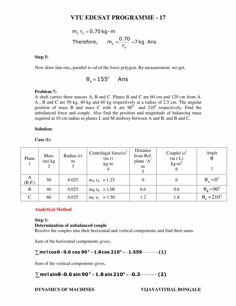
DYNAMICS OF MACHINES VIJAYAVITHAL BONGALE
Ans kg7 r
0.70 m Therefore,
m-kg0.70r m
A
A
AA
==
=
Step 5:
Now draw line omA parallel to od of the force polygon. By measurement, we get,
Ans155θ 0
A=
Problem 7:
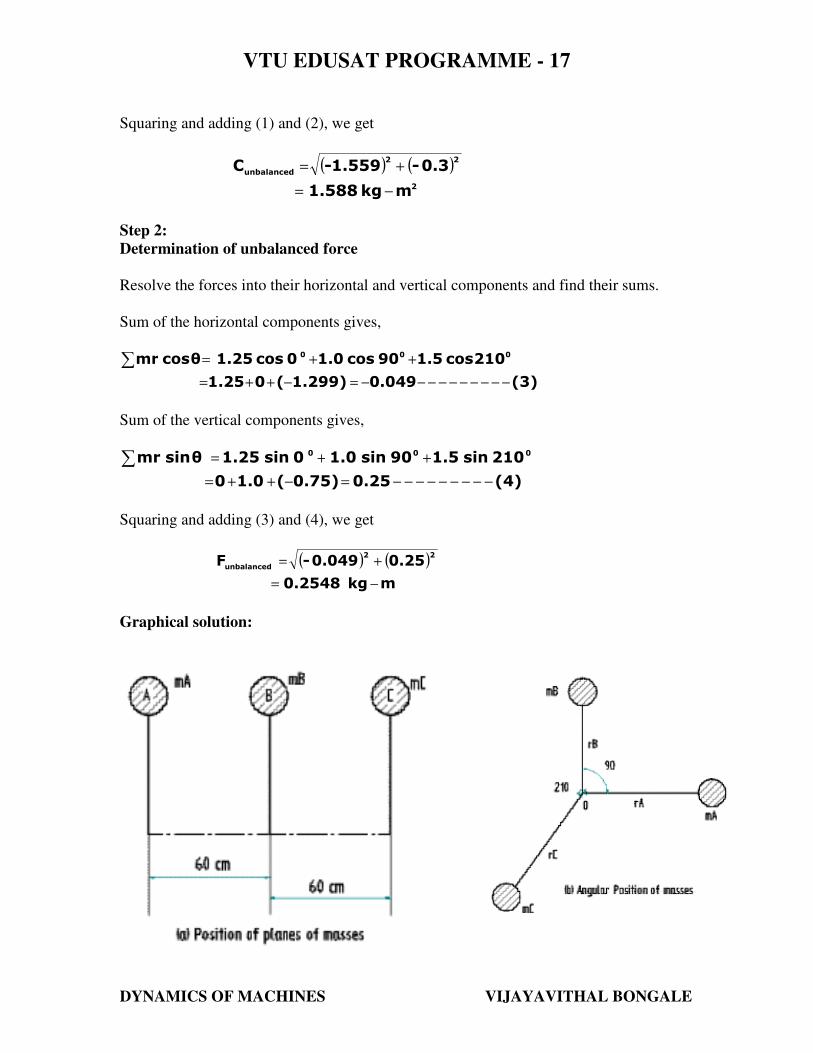
A shaft carries three masses A, B and C. Planes B and C are 60 cm and 120 cm from A.
A , B and C are 50 kg, 40 kg and 60 kg respectively at a radius of 2.5 cm. The angular
position of mass B and mass C with A are 900 and 210
0 respectively. Find the
unbalanced force and couple. Also find the position and magnitude of balancing mass
required at 10 cm radius in planes L and M midway between A and B, and B and C.
Solution:
Case (i):
Plane
1
Mass
(m) kg
2
Radius (r)
m
3
Centrifugal force/ω2
(m r)
kg-m
4
Distance
from Ref.
plane ‘A’
m
5
Couple/ ω2
(m r L)
kg-m2
6
Angle
θ
7
A
(R.P.) 50 0.025 mA rA = 1.25 0 0
00=θ
A
B 40 0.025 mB rB = 1.00 0.6 0.6 0
90=θB
C 60 0.025 mC rC = 1.50 1.2 1.8 0
210=θC
Analytical Method
Step 1:
Determination of unbalanced couple
Resolve the couples into their horizontal and vertical components and find their sums.
Sum of the horizontal components gives,
(1)1.559210cos1.890cos0.6θcoslmr 00 −−−−−−=+=∑
Sum of the vertical components gives,
(2)0.3210sin1.890sin0.6θsinlmr 00 −−−−−−=+=∑
VTU EDUSAT PROGRAMME - 17
DYNAMICS OF MACHINES VIJAYAVITHAL BONGALE
Squaring and adding (1) and (2), we get
( ) ( )2
22
unbalanced
mkg1.588
0.3-1.559-C
−=
+=
Step 2:
Determination of unbalanced force
Resolve the forces into their horizontal and vertical components and find their sums.
Sum of the horizontal components gives,
(3)0.0491.299)(01.25
210cos1.590cos1.00cos1.25 θcosmr 000
−−−−−−−−−−=−++=
++=∑
Sum of the vertical components gives,
(4)0.250.75)(1.00
210sin1.590sin1.00sin1.25 θsinmr 000
−−−−−−−−−=−++=
++=∑
Squaring and adding (3) and (4), we get
( ) ( )
mkg0.2548
0.250.049-F22
unbalanced
−=
+=
Graphical solution:
VTU EDUSAT PROGRAMME - 17
DYNAMICS OF MACHINES VIJAYAVITHAL BONGALE
`
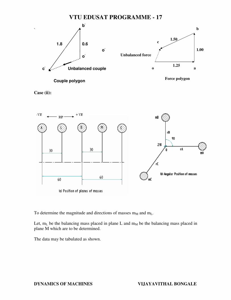
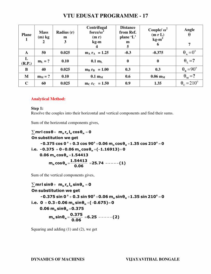
Case (ii):
To determine the magnitude and directions of masses mM and mL.
Let, mL be the balancing mass placed in plane L and mM be the balancing mass placed in
plane M which are to be determined.
The data may be tabulated as shown.
c’
b’
o’
1.8 0.6
Unbalanced couple
Couple polygon
o’
c’
b’
o’
1.8 0.6
Unbalanced couple
Couple polygon
o’
Unbalanced force
1.50
1.00
1.25 o
a
b
c
Force polygon
VTU EDUSAT PROGRAMME - 17
DYNAMICS OF MACHINES VIJAYAVITHAL BONGALE
Plane
1
Mass
(m) kg
2
Radius (r)
m
3
Centrifugal
force/ω2
(m r)
kg-m
4
Distance
from Ref.
plane ‘L’
m
5
Couple/ ω2
(m r L)
kg-m2
6
Angle
θ
7
A 50 0.025 mA rA = 1.25 -0.3 -0.375 0
0=θA
L
(R.P.) mL = ? 0.10 0.1 mL 0 0 ?
L=θ
B 40 0.025 mB rB = 1.00 0.3 0.3 0
90=θB
M mM = ? 0.10 0.1 mM 0.6 0.06 mM ?M
=θ
C 60 0.025 mC rC = 1.50 0.9 1.35 0
210=θC
Analytical Method:
Step 1:
Resolve the couples into their horizontal and vertical components and find their sums.
Sum of the horizontal components gives,
(1)25.740.06
1.54413θcosm
1.54413θcosm0.06
01.16913)(θcosm0.0600.375-i.e.
0210cos1.35θcosm0.0690cos0.30cos0.375-
getweonsubstitutiOn
0 θcoslrmθcoslmr
MM
MM
MM
0
MM
00
MMMM
−−−−−==
=
=−+++
=+++
=+∑
Sum of the vertical components gives,
(2)6.250.06
0.375θsinm
0.375θsinm0.06
00.675)(θsinm0.060.30i.e.
0210sin1.35θsinm0.0690sin0.30sin0.375-
getweonsubstitutiOn
0 θsinlrmθsinlmr
MM
MM
MM
0
MM
00
MMMM
−−−−−==
=
=−+++
=+++
=+∑
Squaring and adding (1) and (2), we get
VTU EDUSAT PROGRAMME - 17
DYNAMICS OF MACHINES VIJAYAVITHAL BONGALE
Anskg26.5mand701.61mi.e.
701.61(6.25)(25.74))θsin(m)θcos(m
M
2
M
222
MM
2
MM
==
=+=+
Dividing (2) by (1), we get
Ans13.65θand25.74
6.25θtan 0
MM==
Step 2:
Resolve the forces into their horizontal and vertical components and find their sums.
Sum of the horizontal components gives,
(3)25.2510.1
2.5251θcosmand
02.5251θcosm0.1
Therefore
01.299)(2.57410θcosm0.11.25
0210cos1.513.65cos2.64990cos1.0θcosm0.10cos1.25
getweonsubstitutiOn
0 θcosrmθcosrmθcosmr
LL
LL
LL
000
LL
0
MMMLLL
−−−−−−−−−−=−
=
=+
=−++++
=++++
=++∑
Sum of the vertical components gives,
(4)8.7510.1
0.8751θsinmand
00.8751θsinm0.1
Therefore
00.75)(0.62511θsinm0.10
0210sin1.513.65sin2.64990sin1.0θsinm0.10sin1.25
getweonsubstitutiOn
0 θsinrmθsinrmθsinmr
LL
LL
LL
000
LL
0
MMMLLL
−−−−−−−−−−=−
=
=+
=−++++
=++++
=++∑
Squaring and adding (3) and (4), we get
Anskg26.72mand714.193mi.e.
714.193(-8.751)(-25.251))θsin(m)θcos(m
L
2
L
222
LL
2
LL
==
=+=+
Dividing (4) by (3), we get
VTU EDUSAT PROGRAMME - 17
DYNAMICS OF MACHINES VIJAYAVITHAL BONGALE
Ans19.11θand25.251-
8.751θtan 0
LL=
−=
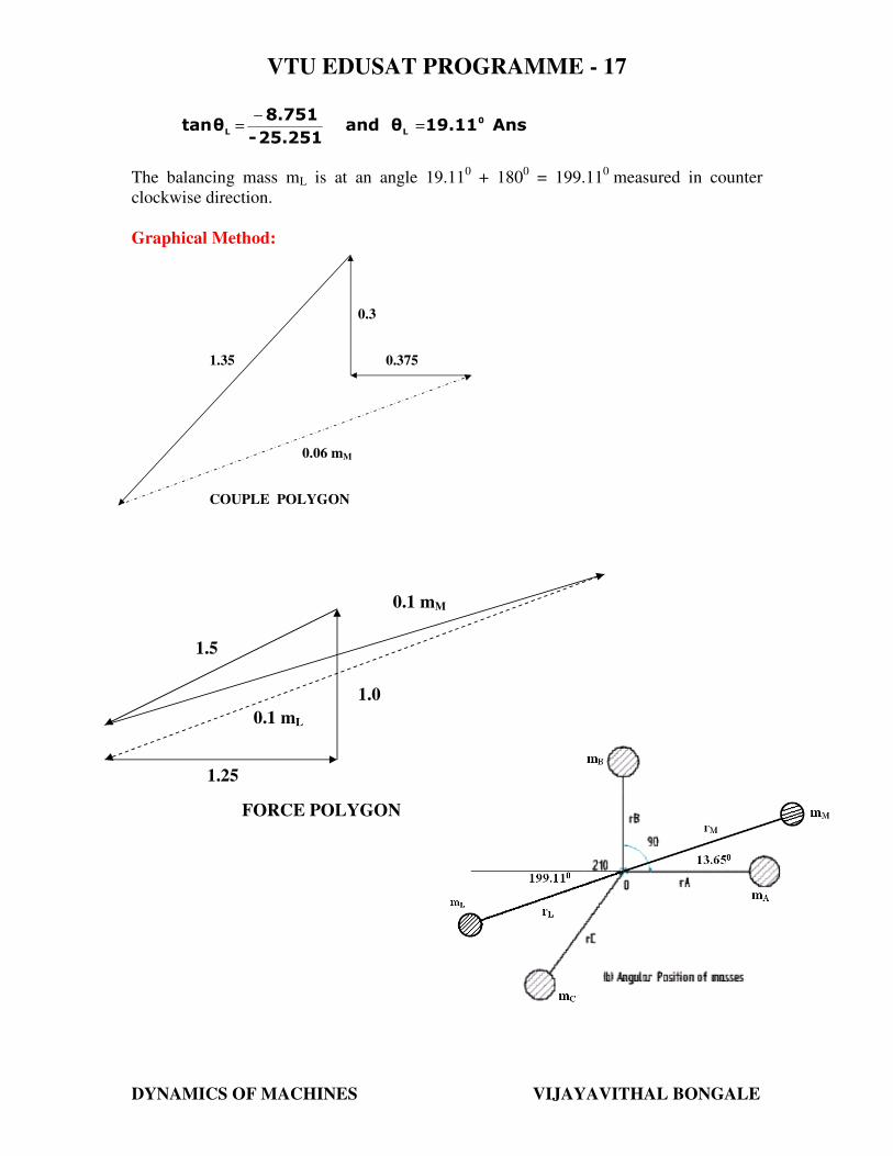
The balancing mass mL is at an angle 19.110 + 180
0 = 199.11
0 measured in counter
clockwise direction.
Graphical Method:
1.35
0.3
0.375
0.06 mM
COUPLE POLYGON
0.1 mL
0.1 mM
1.5
1.25
1.0
FORCE POLYGON
VTU EDUSAT PROGRAMME - 17
DYNAMICS OF MACHINES VIJAYAVITHAL BONGALE
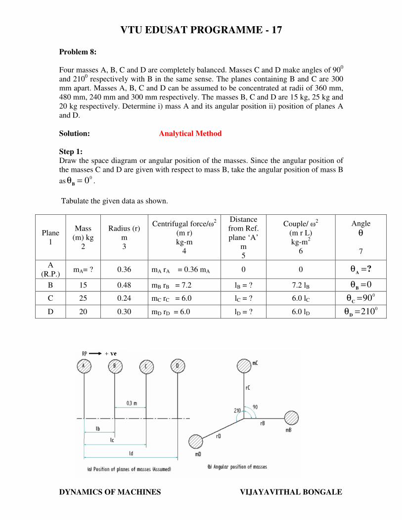
Problem 8:
Four masses A, B, C and D are completely balanced. Masses C and D make angles of 900
and 2100 respectively with B in the same sense. The planes containing B and C are 300
mm apart. Masses A, B, C and D can be assumed to be concentrated at radii of 360 mm,
480 mm, 240 mm and 300 mm respectively. The masses B, C and D are 15 kg, 25 kg and
20 kg respectively. Determine i) mass A and its angular position ii) position of planes A
and D.
Solution: Analytical Method
Step 1:
Draw the space diagram or angular position of the masses. Since the angular position of
the masses C and D are given with respect to mass B, take the angular position of mass B
as0
0=θB
.
Tabulate the given data as shown.
Plane
1
Mass
(m) kg
2
Radius (r)
m
3
Centrifugal force/ω2
(m r)
kg-m
4
Distance
from Ref.
plane ‘A’
m
5
Couple/ ω2
(m r L)
kg-m2
6
Angle
θ
7
A
(R.P.) mA= ? 0.36 mA rA = 0.36 mA 0 0 ?
A=θ
B 15 0.48 mB rB = 7.2 lB = ? 7.2 lB 0=θB
C 25 0.24 mC rC = 6.0 lC = ? 6.0 lC 0
90=θC
D 20 0.30 mD rD = 6.0 lD = ? 6.0 lD 0
210=θD
VTU EDUSAT PROGRAMME - 17
DYNAMICS OF MACHINES VIJAYAVITHAL BONGALE
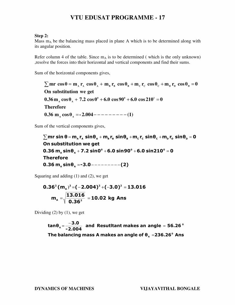
Step 2:
Mass mA be the balancing mass placed in plane A which is to be determined along with
its angular position.
Refer column 4 of the table. Since mA is to be determined ( which is the only unknown)
,resolve the forces into their horizontal and vertical components and find their sums.
Sum of the horizontal components gives,
(1)2.004-θcosm0.36
Therefore
0 210cos6.090cos6.00cos7.2θcosm 0.36
getweonsubstitutiOn
0 θcosrmθcosrmθcosrmθcosrmθcosmr
AA
00
AA
DDDCCCBBBAAA
−−−−−−−−−=
=+++
=+++=∑
0
Sum of the vertical components gives,
(2)3.0-θsinm0.36
Therefore
0 210sin6.090sin6.00sin7.2θsinm 0.36
getweonsubstitutiOn
0 θsinrmθsinrmθsinrmθsinrmθsinmr
AA
000
AA
DDDCCCBBBAAA
−−−−−−−−−=
=+++
=+++=∑
Squaring and adding (1) and (2), we get
Anskg10.020.36
13.016m
13.0163.0)(2.004)((m0.36
2A
222
A
2
==
=−+−=)
Dividing (2) by (1), we get
Ans236.26θ of angle an makes Amass balancing The
56.26angleanmakesResutltantand2.004-
3.0θtan
0
A
0
A
=
=−
=
VTU EDUSAT PROGRAMME - 17
DYNAMICS OF MACHINES VIJAYAVITHAL BONGALE
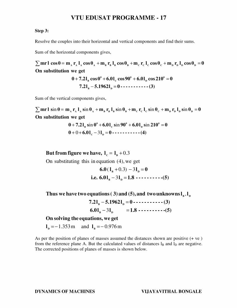
Step 3:
Resolve the couples into their horizontal and vertical components and find their sums.
Sum of the horizontal components gives,
(3)----------- 0 l5.1962l7.2
0 210cosl6.090cosl6.00cosl7.20
getweonsubstitutiOn
0 θcoslrmθcoslrmθcoslrmθcoslrm θcoslmr
DB
0
D
0
C
0
B
DDDDCCCCBBBBAAAA
=−
=+++
=+++=∑
Sum of the vertical components gives,
(4)----------- 0 ll6.00
0 210sl6.090sl6.00sl7.20
getweonsubstitutiOn
0 θslrmθslrmθslrmθslrm θslmr
DC
0
D
0
C
0
B
DDDDCCCCBBBBAAAA
=−++
=+++
=+++=∑
30
ininin
ininininin
m976.0andm353.1
3
,
3
3)3.0(
getwe),4(equationinthisngsubstitutiOn
3.0
−=−=
=−
=−
=−
=−+
+=
BD
DB
DB
DB
DB
DB
BC
ll
get we equations, the solving On
-(5)---------1.8 ll6.0
(3)----------- 0 l5.1962l7.2
llunknownstwoand (5), and 3) ( equations two have we Thus
-(5)---------1.8 ll6.0i.e.
0 ll 6.0
l l have, we figure fromBut
As per the position of planes of masses assumed the distances shown are positive (+ ve )
from the reference plane A. But the calculated values of distances lB and lD are negative.
The corrected positions of planes of masses is shown below.
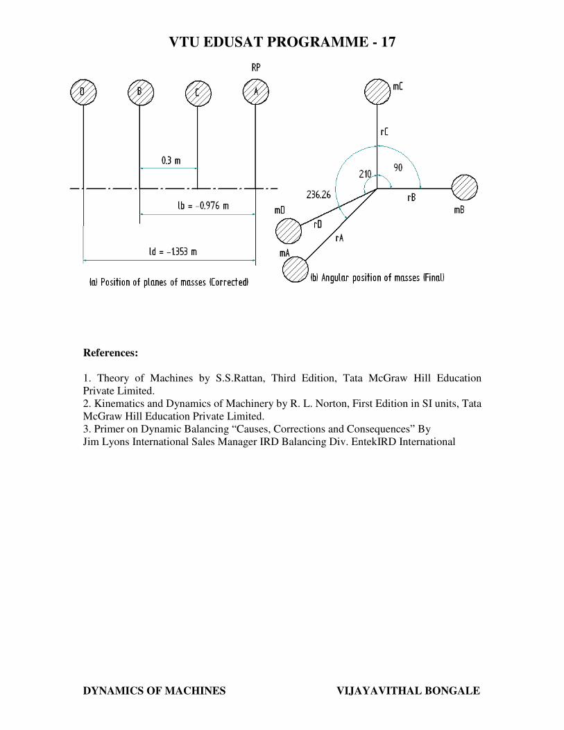
VTU EDUSAT PROGRAMME - 17
DYNAMICS OF MACHINES VIJAYAVITHAL BONGALE
References:
1. Theory of Machines by S.S.Rattan, Third Edition, Tata McGraw Hill Education
Private Limited.
2. Kinematics and Dynamics of Machinery by R. L. Norton, First Edition in SI units, Tata
McGraw Hill Education Private Limited.
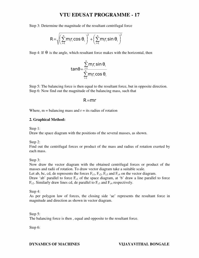
3. Primer on Dynamic Balancing “Causes, Corrections and Consequences” By
Jim Lyons International Sales Manager IRD Balancing Div. EntekIRD International


![338 40 TURBOMACHINERY SYMPOSIUM CASE STUDY · 750 17.4 62.1 22.3 79.8 1000 14.4 51.3 25.1 89.7 NDE DE Balancing plane Residual unbalance [kg mm] Residual unbalance mass [g] API 541requirement](https://static.fdocuments.in/doc/165x107/606c68cfc65f5462f8774710/338-40-turbomachinery-symposium-case-study-750-174-621-223-798-1000-144-513.jpg)