BALANCING OF RECIPROCATING MASSES - … · RECIPROCATING MASSES BALANCING OF RECIPROCATING MASSES...
43
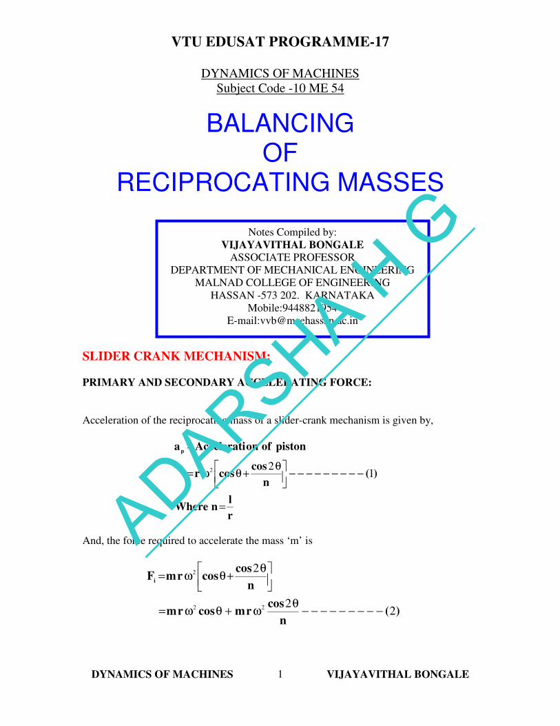
VTU EDUSAT PROGRAMME-17 DYNAMICS OF MACHINES VIJAYAVITHAL BONGALE 1 DYNAMICS OF MACHINES Subject Code -10 ME 54 BALANCING OF RECIPROCATING MASSES BALANCING OF RECIPROCATING MASSES SLIDER CRANK MECHANISM: PRIMARY AND SECONDARY ACCELERATING FORCE: Acceleration of the reciprocating mass of a slider-crank mechanism is given by, r l n Where ) ( n cos cos r piston of on Accelerati a p = - - - - - - - - - θ + θ ω = = 1 2 2 And, the force required to accelerate the mass ‘m’ is ) ( n cos r m cos r m n cos cos r m F i 2 2 2 2 2 2 - - - - - - - - - θ ω + θ ω = θ + θ ω = Notes Compiled by: VIJAYAVITHAL BONGALE ASSOCIATE PROFESSOR DEPARTMENT OF MECHANICAL ENGINEERING MALNAD COLLEGE OF ENGINEERING HASSAN -573 202. KARNATAKA Mobile:9448821954 E-mail:[email protected] ADARSHA H G
Transcript of BALANCING OF RECIPROCATING MASSES - … · RECIPROCATING MASSES BALANCING OF RECIPROCATING MASSES...
VTU EDUSAT PROGRAMME-17
DYNAMICS OF MACHINES VIJAYAVITHAL BONGALE
1
DYNAMICS OF MACHINES
Subject Code -10 ME 54
BALANCING
OF
RECIPROCATING MASSES
BALANCING
OF
RECIPROCATING MASSES
SLIDER CRANK MECHANISM:
PRIMARY AND SECONDARY ACCELERATING FORCE:
Acceleration of the reciprocating mass of a slider-crank mechanism is given by,
r
lnWhere
)(n
coscosr
pistonofonAcceleratiap
=
−−−−−−−−−
θ+θω=
=
122
And, the force required to accelerate the mass ‘m’ is
)(n
cosrmcosrm
n
coscosrmF
i
22
2
22
2
−−−−−−−−−θ
ω+θω=
θ+θω=
Notes Compiled by:
VIJAYAVITHAL BONGALE
ASSOCIATE PROFESSOR
DEPARTMENT OF MECHANICAL ENGINEERING
MALNAD COLLEGE OF ENGINEERING
HASSAN -573 202. KARNATAKA
Mobile:9448821954
E-mail:[email protected]
ADARSHA H G
VTU EDUSAT PROGRAMME-17
DYNAMICS OF MACHINES VIJAYAVITHAL BONGALE
2
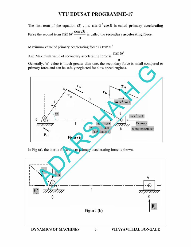
The first term of the equation (2) , i.e. θω cosrm2
is called primary accelerating
force the second term n
cosrm
θω
22 is called the secondary accelerating force.
Maximum value of primary accelerating force is 2
ωrm
And Maximum value of secondary accelerating force is n
rm2
ω
Generally, ‘n’ value is much greater than one; the secondary force is small compared to
primary force and can be safely neglected for slow speed engines.
In Fig (a), the inertia force due to primary accelerating force is shown.
ADARSHA H G
VTU EDUSAT PROGRAMME-17
DYNAMICS OF MACHINES VIJAYAVITHAL BONGALE
3
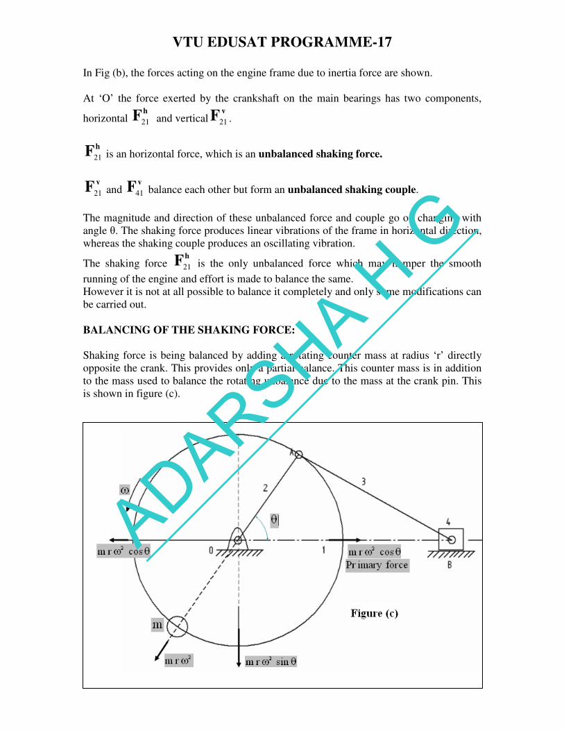
In Fig (b), the forces acting on the engine frame due to inertia force are shown.
At ‘O’ the force exerted by the crankshaft on the main bearings has two components,
horizontal hF21 and vertical
vF21 .
hF21 is an horizontal force, which is an unbalanced shaking force.
vF
21 and vF
41 balance each other but form an unbalanced shaking couple.
The magnitude and direction of these unbalanced force and couple go on changing with
angle θ. The shaking force produces linear vibrations of the frame in horizontal direction,
whereas the shaking couple produces an oscillating vibration.
The shaking force hF21 is the only unbalanced force which may hamper the smooth
running of the engine and effort is made to balance the same.
However it is not at all possible to balance it completely and only some modifications can
be carried out.
BALANCING OF THE SHAKING FORCE:
Shaking force is being balanced by adding a rotating counter mass at radius ‘r’ directly
opposite the crank. This provides only a partial balance. This counter mass is in addition
to the mass used to balance the rotating unbalance due to the mass at the crank pin. This
is shown in figure (c).
ADARSHA H G
VTU EDUSAT PROGRAMME-17
DYNAMICS OF MACHINES VIJAYAVITHAL BONGALE
4
The horizontal component of the centrifugal force due to the balancing mass is
θω cosrm2
and this is in the line of stroke. This component neutralizes the unbalanced
reciprocating force. But the rotating mass also has a component θω sinrm2
perpendicular to the line of stroke which remains unbalanced. The unbalanced force is
zero at θ = 00 or 180
0 and maximum at the middle of the stroke i.e. θ = 90
0. The
magnitude or the maximum value of the unbalanced force remains the same i.e. equal to 2
ωrm . Thus instead of sliding to and fro on its mounting, the mechanism tends to
jump up and down.
To minimize the effect of the unbalance force a compromise is, usually made, is 3
2 of the
reciprocating mass is balanced or a value between 2
1 to
4
3.
If ‘c’ is the fraction of the reciprocating mass, then
θcosωrmcmassthebybalancedforceprimaryThe 2=
and
θcosωrmc)1(massthebyunbalancedforceprimaryThe 2−=
θsinωrmc
unbalancedremainswhichforcelcentrifugaofcomponentVertical2
=
In reciprocating engines, unbalance forces in the direction of the line of stroke are more
dangerous than the forces perpendicular to the line of stroke.
[ ] [ ]2222 θsinωrmcθcosωrc)m(1
instantanyatforceunbalancedResultant
+−=
The resultant unbalanced force is minimum when, 2
1=c
This method is just equivalent to as if a revolving mass at the crankpin is completely
balanced by providing a counter mass at the same radius diametrically opposite to the
crank. Thus if P
m is the mass at the crankpin and ‘c’ is the fraction of the reciprocating
mass ‘m’ to be balanced , the mass at the crankpin may be considered as P
mmc +
which is to be completely balanced.
ADARSHA H G
VTU EDUSAT PROGRAMME-17
DYNAMICS OF MACHINES VIJAYAVITHAL BONGALE
5
Problem 1:
A single –cylinder reciprocating engine has a reciprocating mass of 60 kg. The crank
rotates at 60 rpm and the stroke is 320 mm. The mass of the revolving parts at 160 mm
radius is 40 kg. If two-thirds of the reciprocating parts and the whole of the revolving
parts are to be balanced, determine the, (i) balance mass required at a radius of 350 mm
and (ii) unbalanced force when the crank has turned 500 from the top-dead centre.
Solution:
mm350r,3
2ckg,40m
mm320stroketheoflengthLrpm,60N
kg60partsingreciprocattheofmassm:Given
cP===
===
==
(i) Balance mass required at a radius of 350 mm
We have,
mm1602
320
2
Lr
rad/sπ260
60xπ2
60
Nπ2ω
===
===
kg804060x
3
2mmcM
MpincranktheatbalancedbetoMass
P=+=+=
=
and
kg 5736.350
160x80mi.e.
r
rMmthereforerMrm
c
c
ccc
==
==
(ii) Unbalanced force when the crank has turned 500 from the top-dead centre.
( )[ ] [ ]
( ) ( )
N209.9
50sin2πx0.16x60x3
250cos2πx0.16x60x
3
21
θsinωrmcθcosωrmc1
50θat force Unbalanced
2
02
2
02
2222
0
=
+
−=
+−=
=
ADARSHA H G
VTU EDUSAT PROGRAMME-17
DYNAMICS OF MACHINES VIJAYAVITHAL BONGALE
6
Problem 2:
The following data relate to a single cylinder reciprocating engine:
Mass of reciprocating parts = 40 kg
Mass of revolving parts = 30 kg at crank radius
Speed = 150 rpm, Stroke = 350 mm.
If 60 % of the reciprocating parts and all the revolving parts are to be balanced, determine
the,
(i) balance mass required at a radius of 320 mm and (ii) unbalanced force when the crank
has turned 450 from the top-dead centre.
Solution:
mm320r,%60c
mm350stroketheoflengthLrpm,150N ,kg30m
kg40partsingreciprocattheofmassm:Given
c
P
==
====
==
(i) Balance mass required at a radius of 350 mm
We have,
mm1752
350
2
Lr
rad/s15.760
150xπ2
60
Nπ2ω
===
===
kg543040x0.60mmcM
MpincranktheatbalancedbetoMass
P=+=+=
=
and
kg29.53320
175x54mi.e.
r
rMmthereforerMrm
c
c
ccc
==
==
(ii) Unbalanced force when the crank has turned 450 from the top-dead centre.
( )[ ] [ ]
( ) ( )[ ] ( )[ ]N880.7
45sin15.7x0.175x40x0.6045cos15.7x0.175x40x0.601
θsinωrmcθcosωrmc1
45θat force Unbalanced
2022
02
2222
0
=
+−=
+−=
=
ADARSHA H G
VTU EDUSAT PROGRAMME-17
DYNAMICS OF MACHINES VIJAYAVITHAL BONGALE
7
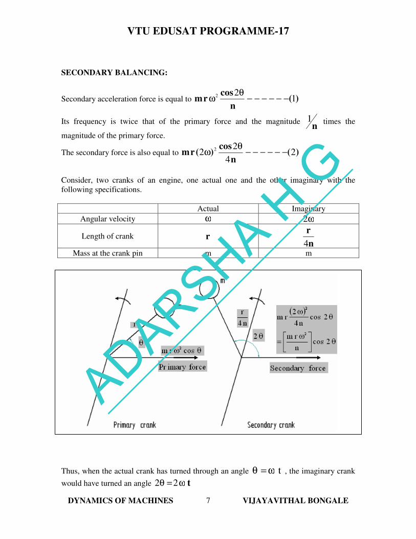
SECONDARY BALANCING:
Secondary acceleration force is equal to )(n
cosrm 1
22−−−−−−
θω
Its frequency is twice that of the primary force and the magnitude n
1 times the
magnitude of the primary force.
The secondary force is also equal to )(n
cos)(rm 2
4
22
2−−−−−−
θω
Consider, two cranks of an engine, one actual one and the other imaginary with the
following specifications.
Actual Imaginary
Angular velocity ω ω2
Length of crank r n
r
4
Mass at the crank pin m m
Thus, when the actual crank has turned through an angle tω=θ , the imaginary crank
would have turned an angle tω=θ 22
ADARSHA H G
VTU EDUSAT PROGRAMME-17
DYNAMICS OF MACHINES VIJAYAVITHAL BONGALE
8
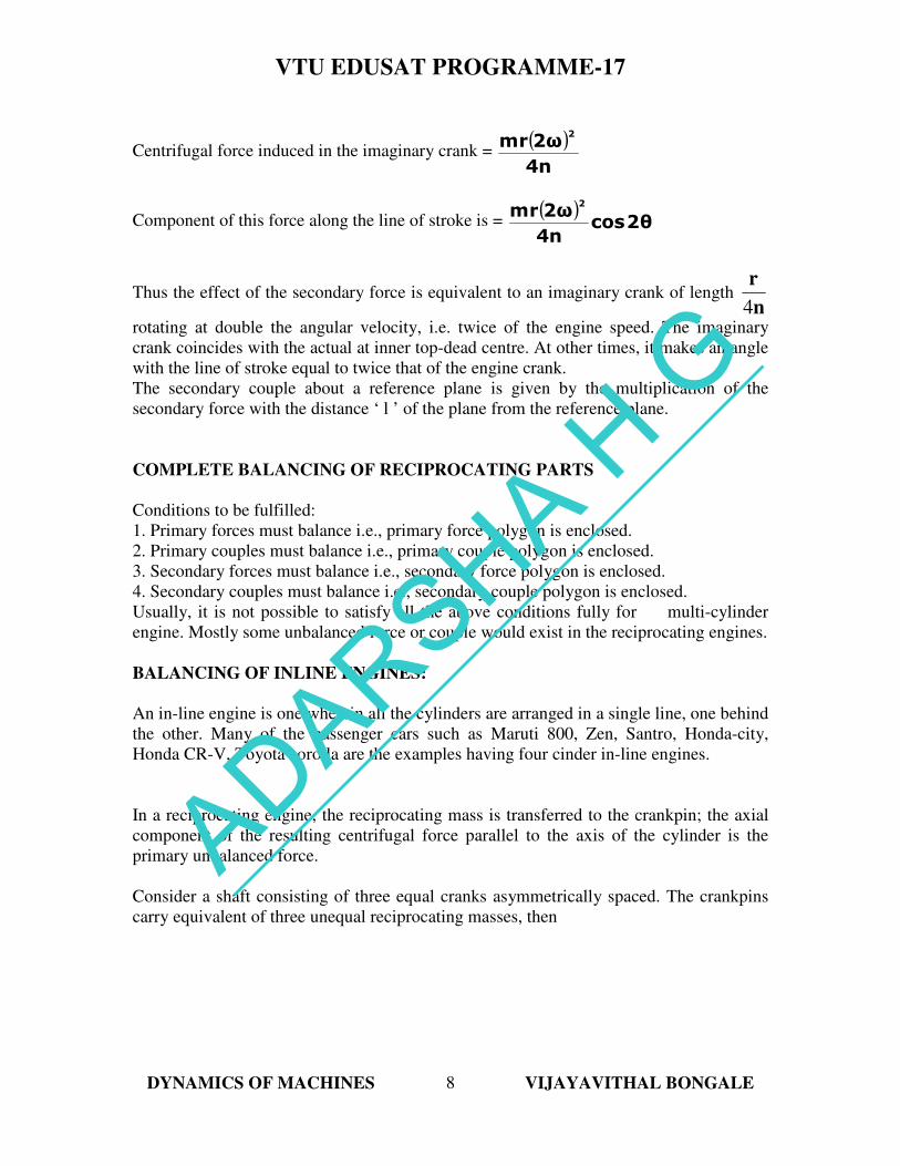
Centrifugal force induced in the imaginary crank = ( )4n
2ωrm2
Component of this force along the line of stroke is = ( )
2θcos4n
2ωrm2
Thus the effect of the secondary force is equivalent to an imaginary crank of length n
r
4
rotating at double the angular velocity, i.e. twice of the engine speed. The imaginary
crank coincides with the actual at inner top-dead centre. At other times, it makes an angle
with the line of stroke equal to twice that of the engine crank.
The secondary couple about a reference plane is given by the multiplication of the
secondary force with the distance ‘ l ’ of the plane from the reference plane.
COMPLETE BALANCING OF RECIPROCATING PARTS
Conditions to be fulfilled:
1. Primary forces must balance i.e., primary force polygon is enclosed.
2. Primary couples must balance i.e., primary couple polygon is enclosed.
3. Secondary forces must balance i.e., secondary force polygon is enclosed.
4. Secondary couples must balance i.e., secondary couple polygon is enclosed.
Usually, it is not possible to satisfy all the above conditions fully for multi-cylinder
engine. Mostly some unbalanced force or couple would exist in the reciprocating engines.
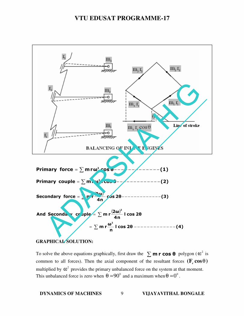
BALANCING OF INLINE ENGINES:
An in-line engine is one wherein all the cylinders are arranged in a single line, one behind
the other. Many of the passenger cars such as Maruti 800, Zen, Santro, Honda-city,
Honda CR-V, Toyota corolla are the examples having four cinder in-line engines.
In a reciprocating engine, the reciprocating mass is transferred to the crankpin; the axial
component of the resulting centrifugal force parallel to the axis of the cylinder is the
primary unbalanced force.
Consider a shaft consisting of three equal cranks asymmetrically spaced. The crankpins
carry equivalent of three unequal reciprocating masses, then
ADARSHA H G
VTU EDUSAT PROGRAMME-17
DYNAMICS OF MACHINES VIJAYAVITHAL BONGALE
9
∑ −−−−−−−−−−−−−= (1)θcosωrmforcePrimary 2
∑ −−−−−−−−−−−−−= (2)θcoslωrmcouplePrimary 2
( )∑ −−−−−−−−−−−−−= (3)2θcos
n4
2ωrmforceSecondary
2
( )
∑
∑
−−−−−−−−−−−−−=
=
(4)2θcosln
ωrm
2θcosln4
2ωrmcoupleSecondary And
2
2
GRAPHICAL SOLUTION:
To solve the above equations graphically, first draw the ∑ θcosrm polygon (2
ω is
common to all forces). Then the axial component of the resultant forces )cosF(r
θ
multiplied by 2
ω provides the primary unbalanced force on the system at that moment.
This unbalanced force is zero when 0
90=θ and a maximum when0
0=θ .
ADARSHA H G
VTU EDUSAT PROGRAMME-17
DYNAMICS OF MACHINES VIJAYAVITHAL BONGALE
10
If the force polygon encloses, the resultant as well as the axial component will always be
zero and the system will be in primary balance.
Then,
00 == ∑∑ VPhPFandF
To find the secondary unbalance force, first find the positions of the imaginary secondary
cranks. Then transfer the reciprocating masses and multiply the same by ( )
n4
22
ω or
n
2ω
to get the secondary force.
In the same way primary and secondary couple ( m r l ) polygon can be drawn for
primary and secondary couples.
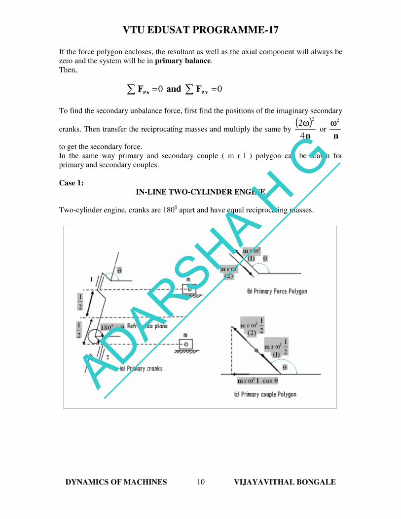
Case 1:
IN-LINE TWO-CYLINDER ENGINE
Two-cylinder engine, cranks are 1800 apart and have equal reciprocating masses.
ADARSHA H G
VTU EDUSAT PROGRAMME-17
DYNAMICS OF MACHINES VIJAYAVITHAL BONGALE
11
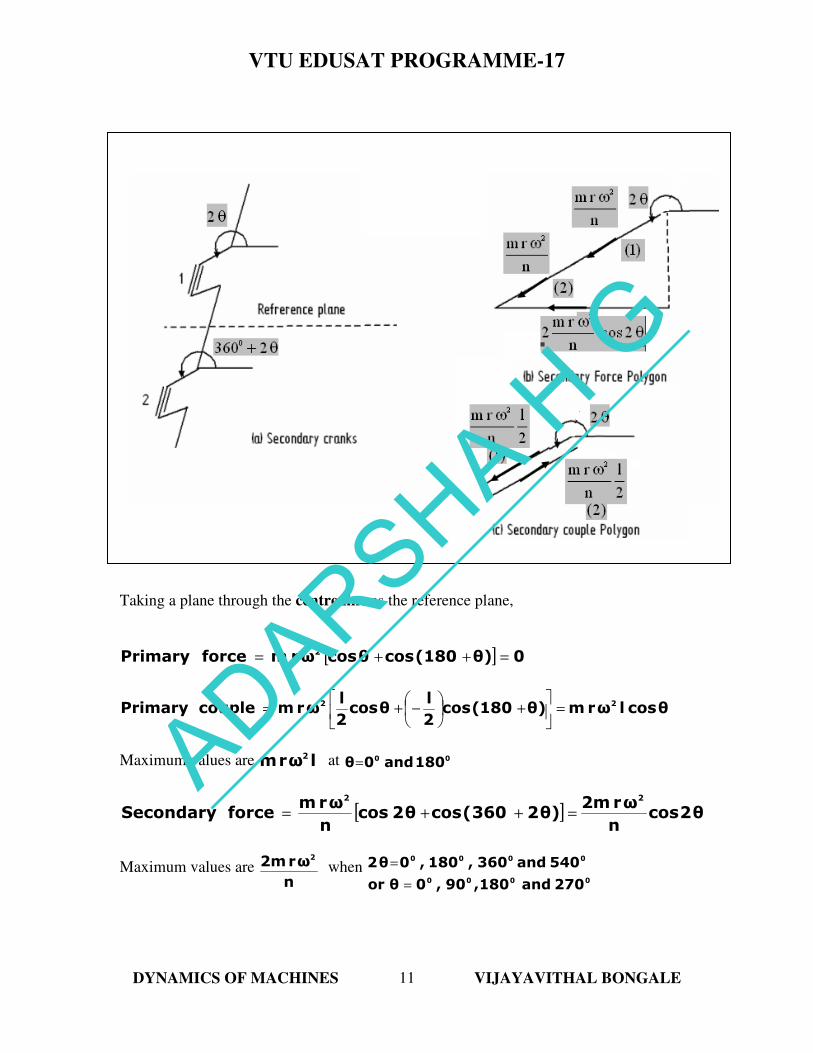
Taking a plane through the centre line as the reference plane,
[ ] 0θ)180(cosθcosωrmforcePrimary 2=++=
θcoslωrmθ)180(cos2
lθcos
2
lωrmcouplePrimary 22
=
+
−+=
Maximum values are lωrm 2 at 00 180and0θ=
[ ] θ2cosn
ωr2mθ)2360(cosθ2cos
n
ωrmforceSecondary
22
=++=
Maximum values are n
ωr2m 2
when 0000
0000
270and180,90,0θor
540and360,180,0θ2
=
=
ADARSHA H G
VTU EDUSAT PROGRAMME-17
DYNAMICS OF MACHINES VIJAYAVITHAL BONGALE
12
0)2θ360(cos2
l2θcos
2
l
n
ωrmcoupleSecondary
2
=
+
−+=
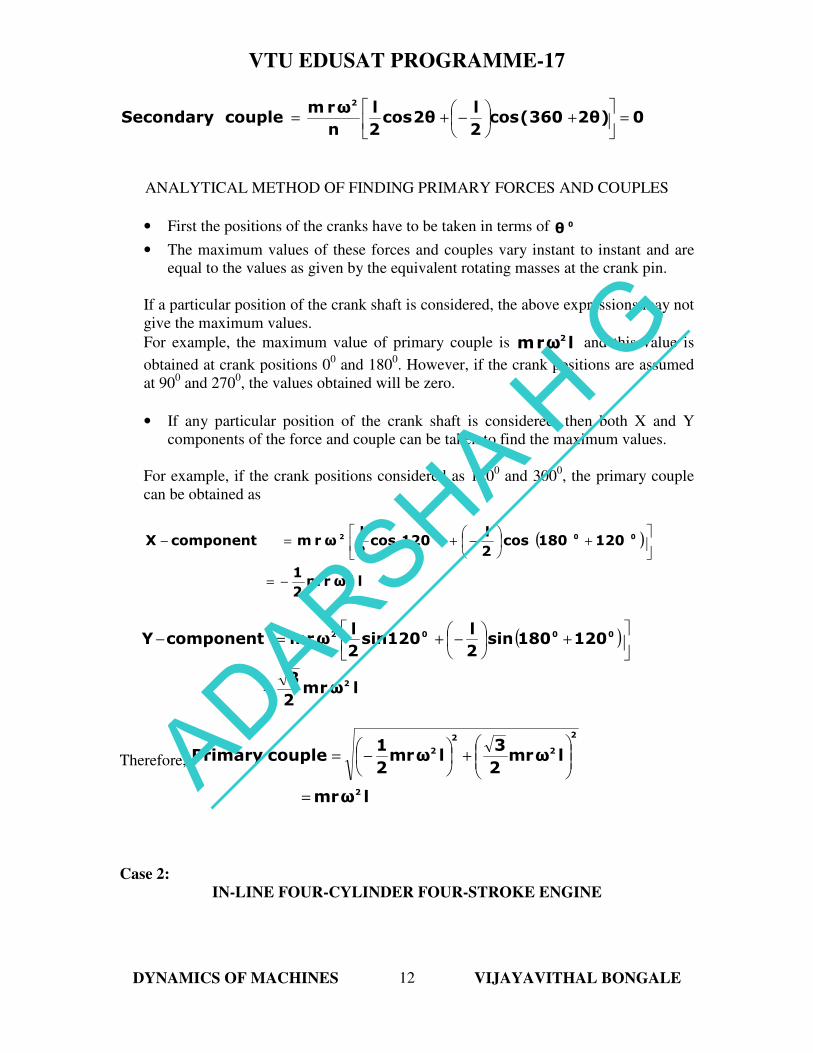
ANALYTICAL METHOD OF FINDING PRIMARY FORCES AND COUPLES
• First the positions of the cranks have to be taken in terms of 0θ
• The maximum values of these forces and couples vary instant to instant and are
equal to the values as given by the equivalent rotating masses at the crank pin.
If a particular position of the crank shaft is considered, the above expressions may not
give the maximum values.
For example, the maximum value of primary couple is lωrm 2 and this value is
obtained at crank positions 00 and 180
0. However, if the crank positions are assumed
at 900 and 270
0, the values obtained will be zero.
• If any particular position of the crank shaft is considered, then both X and Y
components of the force and couple can be taken to find the maximum values.
For example, if the crank positions considered as 1200 and 300
0, the primary couple
can be obtained as
( )
lωrm2
1
120180cos2
l120cos
2
lωrmcomponentX
2
0002
−=
+
−+=−
( )
lωrm2
3
120180sin2
l120sin
2
lωrmcomponentY
2
0002
=
+
−+=−
Therefore,
lωrm
lωrm2
3lωrm
2
1couplePrimary
2
2
2
2
2
=
+
−=
Case 2:
IN-LINE FOUR-CYLINDER FOUR-STROKE ENGINE
ADARSHA H G
VTU EDUSAT PROGRAMME-17
DYNAMICS OF MACHINES VIJAYAVITHAL BONGALE
13
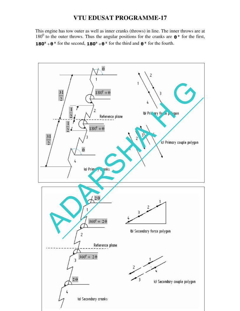
This engine has tow outer as well as inner cranks (throws) in line. The inner throws are at
1800 to the outer throws. Thus the angular positions for the cranks are 0θ for the first,
00 θ180 + for the second, 00 θ180 + for the third and 0θ for the fourth.
ADARSHA H G
VTU EDUSAT PROGRAMME-17
DYNAMICS OF MACHINES VIJAYAVITHAL BONGALE
14
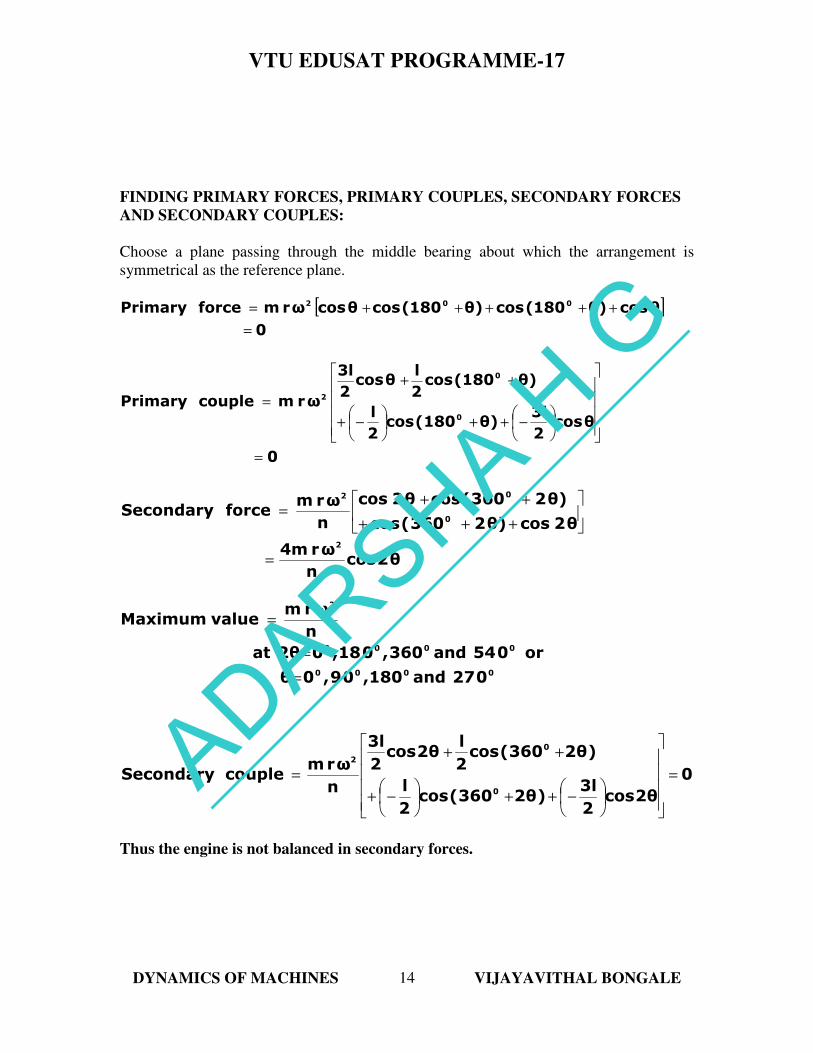
FINDING PRIMARY FORCES, PRIMARY COUPLES, SECONDARY FORCES
AND SECONDARY COUPLES:
Choose a plane passing through the middle bearing about which the arrangement is
symmetrical as the reference plane.
[ ]0
θcosθ)180(cosθ)180(cosθcosωrmforcePrimary 002
=
+++++=
0
θcos2
3lθ)180(cos
2
l
θ)180(cos2
lθcos
2
3l
ωrmcouplePrimary0
0
2
=
−++
−+
++
=
θ2cosn
ωr4m
θ2cosθ)2360(cos
θ)2360(cosθ2cos
n
ωrmforceSecondary
2
0
02
=
+++
++=
0000
0000
2
027and180,09,0θ
or054and360,018,02θat
n
ωrmvalueMaximum
=
=
=
0
2θcos2
3l)2θ360(cos
2
l
)2θ360(cos2
l2θcos
2
3l
n
ωrmcoupleSecondary
0
0
2
=
−++
−+
++
=
Thus the engine is not balanced in secondary forces.
ADARSHA H G
VTU EDUSAT PROGRAMME-17
DYNAMICS OF MACHINES VIJAYAVITHAL BONGALE
15
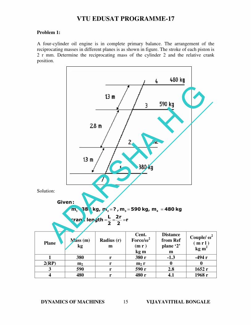
Problem 1:
A four-cylinder oil engine is in complete primary balance. The arrangement of the
reciprocating masses in different planes is as shown in figure. The stroke of each piston is
2 r mm. Determine the reciprocating mass of the cylinder 2 and the relative crank
position.
Solution:
r2
r2
2
Llengthcrank
kg480mkg,590m,?mkg,380m
:Given
4321
===
====
Plane Mass (m)
kg
Radius (r)
m
Cent.
Force/ω2
(m r )
kg m
Distance
from Ref
plane ‘2’
m
Couple/ ω2
( m r l )
kg m2
1 380 r 380 r -1.3 -494 r
2(RP) m2 r m2 r 0 0
3 590 r 590 r 2.8 1652 r
4 480 r 480 r 4.1 1968 r
ADARSHA H G
VTU EDUSAT PROGRAMME-17
DYNAMICS OF MACHINES VIJAYAVITHAL BONGALE
16
Analytical Method:
Choose plane 2 as the reference plane and0
30=θ .
.
Step 1:
Resolve the couples into their horizontal and vertical components and take their sums.
Sum of the horizontal components gives
)(coscos.,e.i
cosrcosrcosr
119681652494
0196801652494
41
4
0
1
−−−−−−−−−θ+=θ+
=θ++θ−
Sum of the vertical components gives
)(sinsin.,e.i
sinrsinrsinr
21968494
0196801652494
41
4
0
1
−−−−−−−−−θ=θ
=θ++θ−
Squaring and adding (1) and (2), we get
( ) ( ) ( )
( ) ( ) ( ) ( )
00
44
2
4
2
44
22
2
4
2
4
2
192.1or167.9θand0.978θcos
get,wesolvingOn
θsin1968θcos1968θcos1968x1652x21652494
θsin1968θcos19681652494
=−=
+++=
++=
.,e.i
Choosing one value, say 0
4167.9θ =
Dividing (2) by (1), we get
0
1
0
0
1
123.4θi.e.,
1.515272.28
412.53
)(167.9cos19681652
)(167.9sin1968θtan
=
−=−
+=
+=
Step 2:
Resolve the forces into their horizontal and vertical components and take their sums.
Sum of the horizontal components gives
)(.cosmor
).(cosrcosrcosrm).(cosr
3588
0916748005904123380
22
00
22
0
−−−−−−−−−−−−−=θ
=++θ+
ADARSHA H G
VTU EDUSAT PROGRAMME-17
DYNAMICS OF MACHINES VIJAYAVITHAL BONGALE
17
Sum of the vertical components gives
)(.sinmor
).(sinrsinrsinrm).(sinr
49417
0916748005904123380
22
00
22
0
−−−−−−−−−−−−−−=θ
=++θ+
Squaring and adding (3) and (4), we get
Anskg.m 14272
=
Dividing (4) by (3), we get
Ansr0
2
2
282θo
4.7288.5
417.9θtan
=
−=−
=
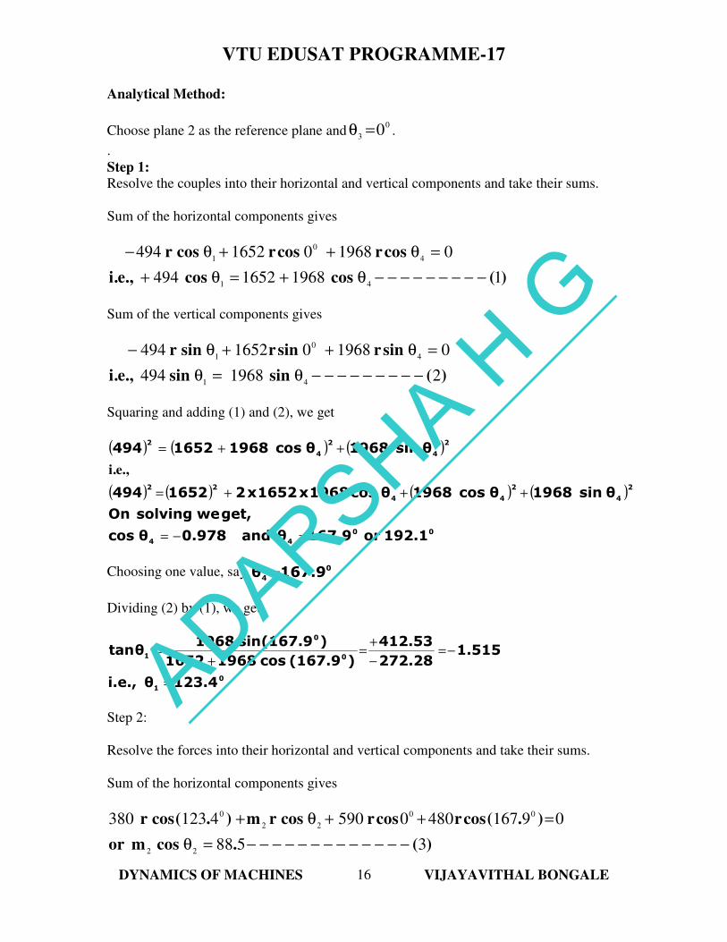
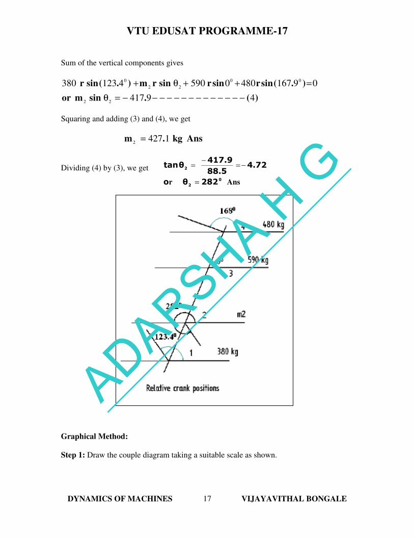
Graphical Method:
Step 1: Draw the couple diagram taking a suitable scale as shown.
ADARSHA H G
VTU EDUSAT PROGRAMME-17
DYNAMICS OF MACHINES VIJAYAVITHAL BONGALE
18
This diagram provides the relative direction of the masses 431mandm,m
.
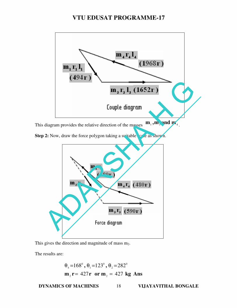
Step 2: Now, draw the force polygon taking a suitable scale as shown.
This gives the direction and magnitude of mass m2.
The results are:
Anskgmorrrm
,,
427427
282123168
22
0
2
0
1
0
4
==
=θ=θ=θ
ADARSHA H G
VTU EDUSAT PROGRAMME-17
DYNAMICS OF MACHINES VIJAYAVITHAL BONGALE
19
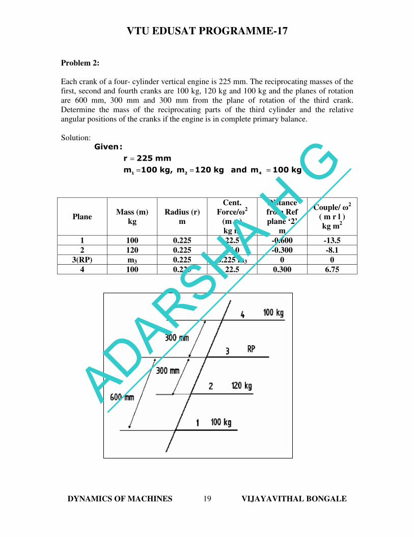
Problem 2:
Each crank of a four- cylinder vertical engine is 225 mm. The reciprocating masses of the
first, second and fourth cranks are 100 kg, 120 kg and 100 kg and the planes of rotation
are 600 mm, 300 mm and 300 mm from the plane of rotation of the third crank.
Determine the mass of the reciprocating parts of the third cylinder and the relative
angular positions of the cranks if the engine is in complete primary balance.
Solution:
kg100mandkg120mkg,100m
mm225r
:Given
421===
=
Plane Mass (m)
kg
Radius (r)
m
Cent.
Force/ω2
(m r )
kg m
Distance
from Ref
plane ‘2’
m
Couple/ ω2
( m r l )
kg m2
1 100 0.225 22.5 -0.600 -13.5
2 120 0.225 27.0 -0.300 -8.1
3(RP) m3 0.225 0.225 m3 0 0
4 100 0.225 22.5 0.300 6.75
ADARSHA H G
VTU EDUSAT PROGRAMME-17
DYNAMICS OF MACHINES VIJAYAVITHAL BONGALE
20
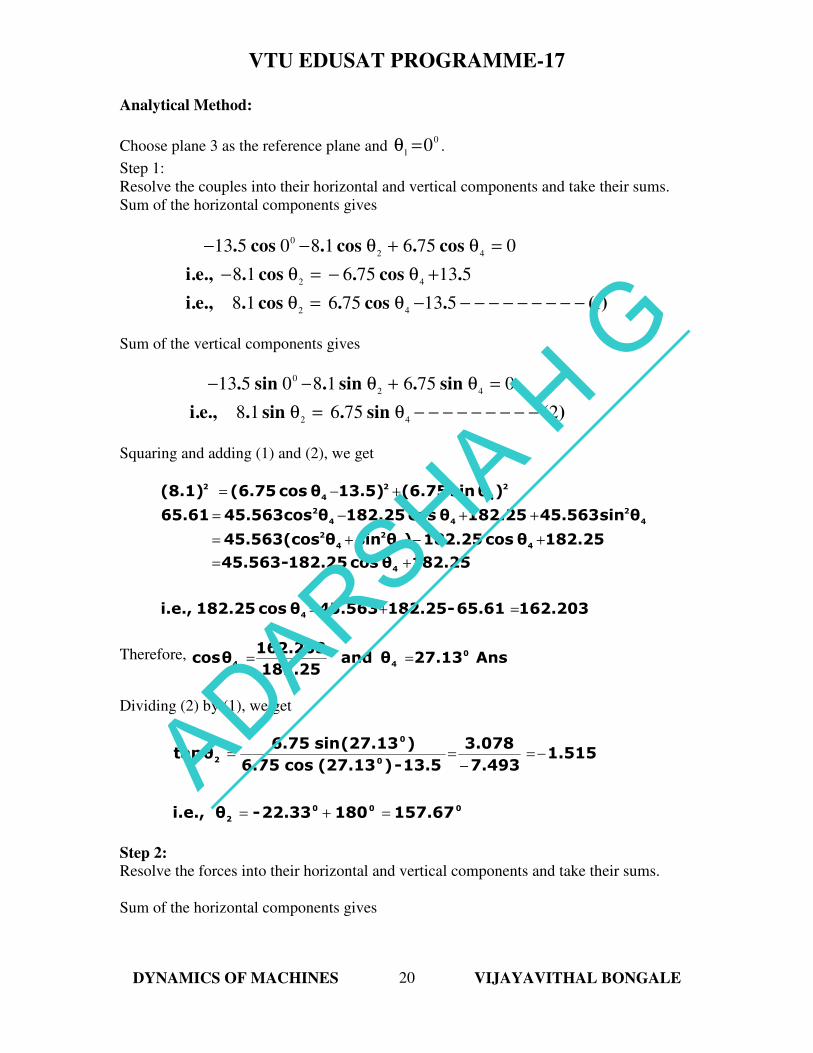
Analytical Method:
Choose plane 3 as the reference plane and 0
10=θ .
Step 1:
Resolve the couples into their horizontal and vertical components and take their sums.
Sum of the horizontal components gives
)(.cos.cos..,e.i
.cos.cos..,e.i
cos.cos.cos.
151375618
51375618
0756180513
42
42
42
0
−−−−−−−−−−θ=θ
+θ−=θ−
=θ+θ−−
Sum of the vertical components gives
)(sin.sin..,e.i
sin.sin.sin.
275618
0756180513
42
42
0
−−−−−−−−−θ=θ
=θ+θ−−
Squaring and adding (1) and (2), we get
162.20365.61-182.2545.563θcos182.25i.e.,
182.25θcos182.25-45.563
182.25θcos182.25)θsinθ45.563(cos
θsin45.563182.25θcos182.25θcos45.56365.61
)θsin(6.7513.5)θcos(6.75(8.1)
4
4
44
2
4
2
4
2
44
2
2
4
2
4
2
=+=
+=
+−+=
++−=
+−=
Therefore, Ans27.13θand182.25
162.203θcos 0
44==
Dividing (2) by (1), we get
000
2
0
0
2
157.6718022.33-θi.e.,
1.5157.493
3.078
13.5-)(27.13cos6.75
)(27.13sin6.75θtan
=+=
−=−
==
Step 2:
Resolve the forces into their horizontal and vertical components and take their sums.
Sum of the horizontal components gives
ADARSHA H G
VTU EDUSAT PROGRAMME-17
DYNAMICS OF MACHINES VIJAYAVITHAL BONGALE
21
(3)17.545θcosm0.225i.e.,
020.02θcosm0.22524.97522.5i.e.,
0)27.13(cos22.5θcosm0.225)(157.67cos27)0(cos22.5
33
33
0
33
00
−−−−−−−−−−−−−−=
=++−
=+++
And sum of the vertical components gives
(4)-20.518θsinm0.225i.e.,
010.26θsinm0.22510.258i.e.,
0)27.13(sin22.5θsinm0.225)(157.67sin27)0(sin22.5
33
33
0
33
00
−−−−−−−−−−−−−−=
=++
=+++
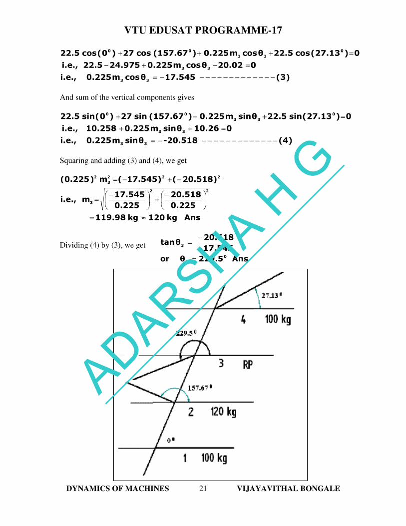
Squaring and adding (3) and (4), we get
Anskg120kg119.98
0.225
20.518
0.225
17.545mi.e.,
20.518)(17.545)(m)(0.225
22
3
222
3
2
≈=
−+
−=
−+−=
Dividing (4) by (3), we get
Ans229.5θor
17.545-
20.518θtan
0
3
3
=
−=
ADARSHA H G
VTU EDUSAT PROGRAMME-17
DYNAMICS OF MACHINES VIJAYAVITHAL BONGALE
22
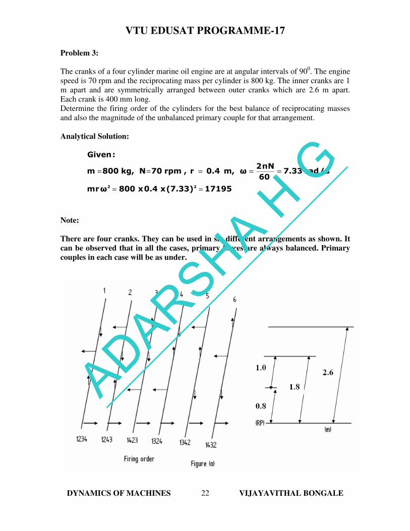
Problem 3:
The cranks of a four cylinder marine oil engine are at angular intervals of 900. The engine
speed is 70 rpm and the reciprocating mass per cylinder is 800 kg. The inner cranks are 1
m apart and are symmetrically arranged between outer cranks which are 2.6 m apart.
Each crank is 400 mm long.
Determine the firing order of the cylinders for the best balance of reciprocating masses
and also the magnitude of the unbalanced primary couple for that arrangement.
Analytical Solution:
17195(7.33)x0.4x800ωrm
s/rad7.3360
Nπ2ωm,0.4r,rpm70Nkg,800m
:Given
22==
=====
Note:
There are four cranks. They can be used in six different arrangements as shown. It
can be observed that in all the cases, primary forces are always balanced. Primary
couples in each case will be as under.
Taking 1 as the reference plane,
ADARSHA H G
VTU EDUSAT PROGRAMME-17
DYNAMICS OF MACHINES VIJAYAVITHAL BONGALE
23
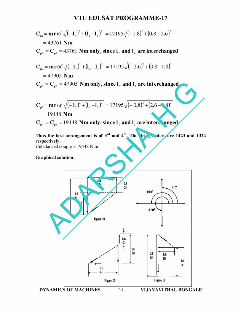
( ) ( ) ( ) ( )
erchangedintarelandlcesin,onlymNCC
mN
...lllrmC
pp
p
4216
222
42
2
3
2
1
43761
43761
62808117195
==
=
−+−=−+−ω=
( ) ( ) ( ) ( )
erchangedintarelandlcesin,onlymNCC
mN
...lllrmC
pp
p
3225
222
32
2
4
2
2
47905
47905
81806217195
==
=
−+−=−+−ω=
( ) ( ) ( ) ( )
erchangedintarelandlcesin,onlymNCC
mN
...lllrmC
pp
p
3434
222
34
2
2
2
3
19448
19448
81628017195
==
=
−+−=−+−ω=
Thus the best arrangement is of 3rd
and 4th
. The firing orders are 1423 and 1324
respectively.
Unbalanced couple = 19448 N m.
Graphical solution:
ADARSHA H G
VTU EDUSAT PROGRAMME-17
DYNAMICS OF MACHINES VIJAYAVITHAL BONGALE
24
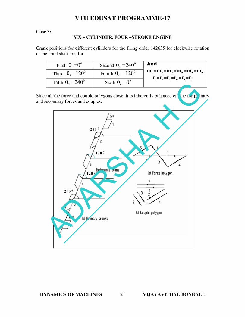
Case 3:
SIX – CYLINDER, FOUR –STROKE ENGINE
Crank positions for different cylinders for the firing order 142635 for clockwise rotation
of the crankshaft are, for
Since all the force and couple polygons close, it is inherently balanced engine for primary
and secondary forces and couples.
First 0
10=θ Second
0
2240=θ
654321
654321
rrrrrr
mmmmmm
And
=====
=====
Third 0
3120=θ Fourth
0
4120=θ
Fifth 0
5240=θ Sixth
0
60=θ
ADARSHA H G
VTU EDUSAT PROGRAMME-17
DYNAMICS OF MACHINES VIJAYAVITHAL BONGALE
25
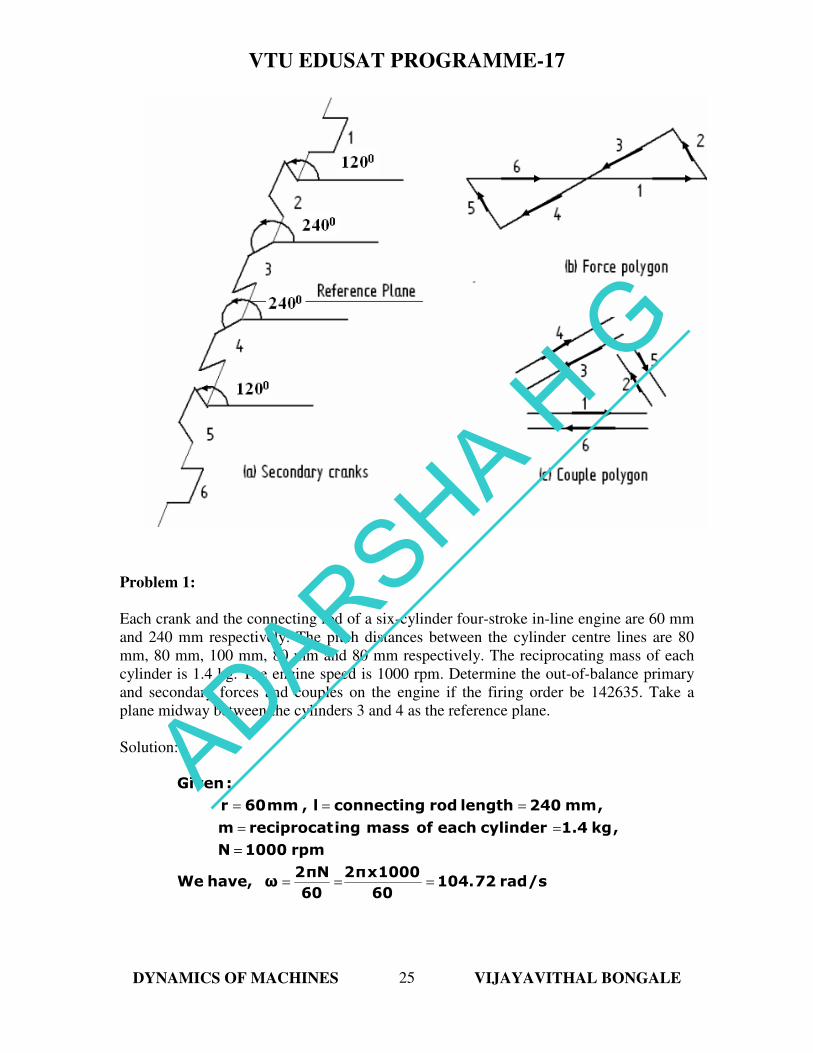
Problem 1:
Each crank and the connecting rod of a six-cylinder four-stroke in-line engine are 60 mm
and 240 mm respectively. The pitch distances between the cylinder centre lines are 80
mm, 80 mm, 100 mm, 80 mm and 80 mm respectively. The reciprocating mass of each
cylinder is 1.4 kg. The engine speed is 1000 rpm. Determine the out-of-balance primary
and secondary forces and couples on the engine if the firing order be 142635. Take a
plane midway between the cylinders 3 and 4 as the reference plane.
Solution:
/srad72104.60
1000xπ2
60
Nπ2ωhave,We
rpm1000N
,kg1.4cylindereachofmassingreciprocatm
,mm240lengthrodconnectingl,mm60r
:Given
===
=
==
===
ADARSHA H G
VTU EDUSAT PROGRAMME-17
DYNAMICS OF MACHINES VIJAYAVITHAL BONGALE
26
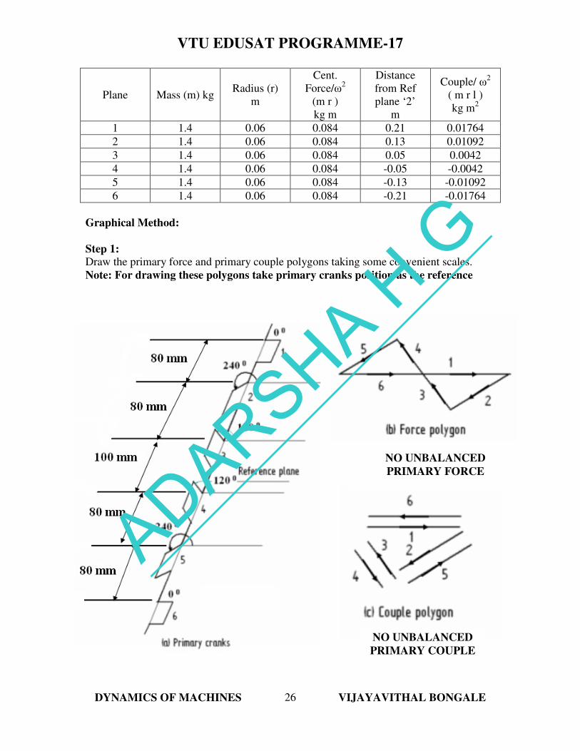
Plane Mass (m) kg Radius (r)
m
Cent.
Force/ω2
(m r )
kg m
Distance
from Ref
plane ‘2’
m
Couple/ ω2
( m r l )
kg m2
1 1.4 0.06 0.084 0.21 0.01764
2 1.4 0.06 0.084 0.13 0.01092
3 1.4 0.06 0.084 0.05 0.0042
4 1.4 0.06 0.084 -0.05 -0.0042
5 1.4 0.06 0.084 -0.13 -0.01092
6 1.4 0.06 0.084 -0.21 -0.01764
Graphical Method:
Step 1:
Draw the primary force and primary couple polygons taking some convenient scales.
Note: For drawing these polygons take primary cranks position as the reference
NO UNBALANCED
PRIMARY FORCE
NO UNBALANCED
PRIMARY COUPLE
ADARSHA H G
VTU EDUSAT PROGRAMME-17
DYNAMICS OF MACHINES VIJAYAVITHAL BONGALE
27
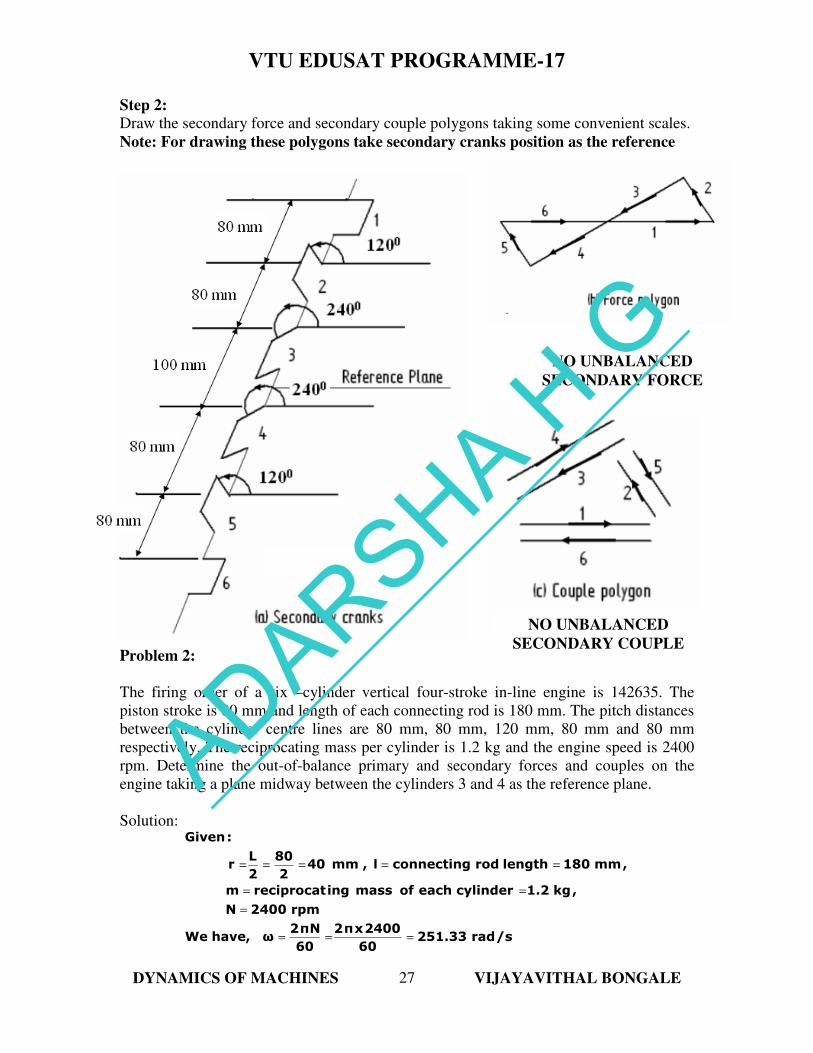
Step 2:
Draw the secondary force and secondary couple polygons taking some convenient scales.
Note: For drawing these polygons take secondary cranks position as the reference
Problem 2:
The firing order of a six –cylinder vertical four-stroke in-line engine is 142635. The
piston stroke is 80 mm and length of each connecting rod is 180 mm. The pitch distances
between the cylinder centre lines are 80 mm, 80 mm, 120 mm, 80 mm and 80 mm
respectively. The reciprocating mass per cylinder is 1.2 kg and the engine speed is 2400
rpm. Determine the out-of-balance primary and secondary forces and couples on the
engine taking a plane midway between the cylinders 3 and 4 as the reference plane.
Solution:
/srad251.3360
2400xπ2
60
Nπ2ωhave,We
rpm2400N
,kg1.2cylindereachofmassingreciprocatm
,mm180lengthrodconnectingl,mm402
80
2
Lr
:Given
===
=
==
=====
NO UNBALANCED
SECONDARY FORCE
NO UNBALANCED
SECONDARY COUPLE
ADARSHA H G
VTU EDUSAT PROGRAMME-17
DYNAMICS OF MACHINES VIJAYAVITHAL BONGALE
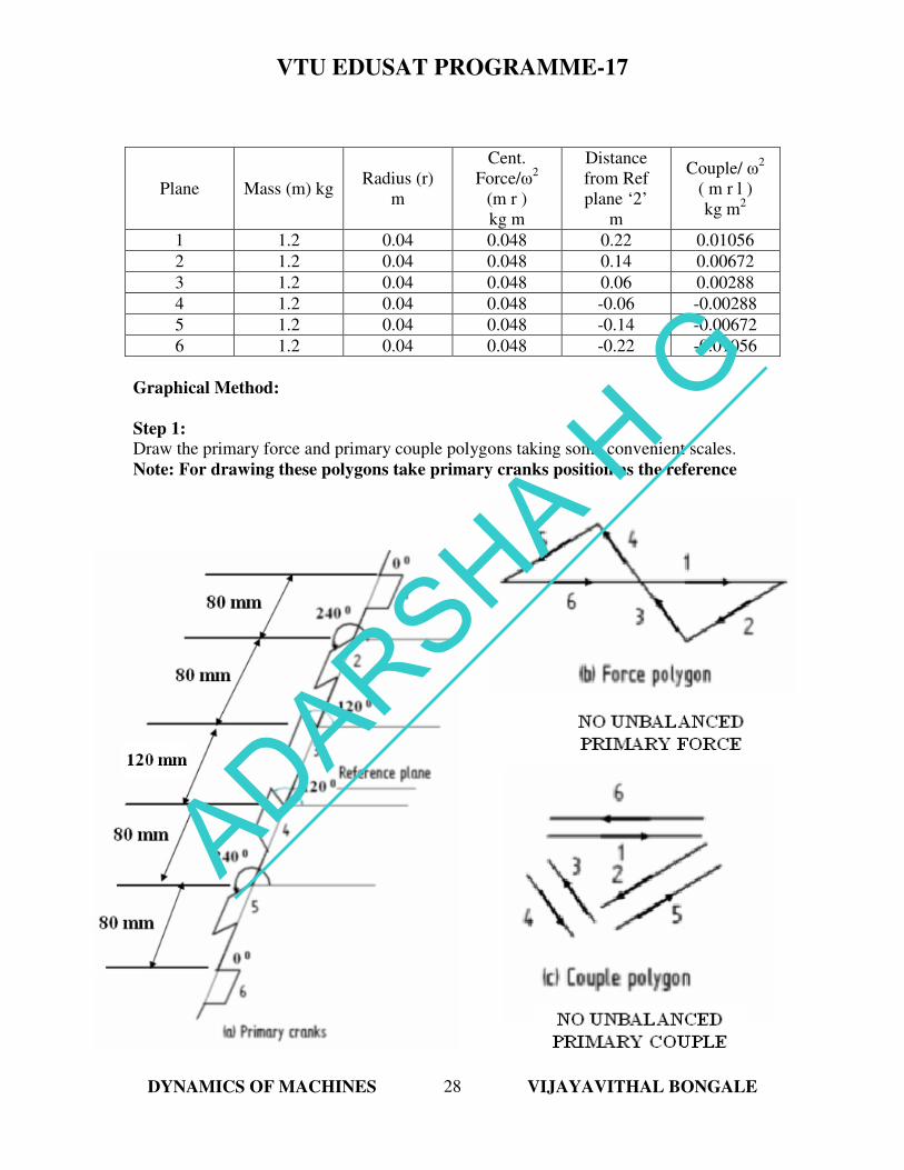
28
Plane Mass (m) kg Radius (r)
m
Cent.
Force/ω2
(m r )
kg m
Distance
from Ref
plane ‘2’
m
Couple/ ω2
( m r l )
kg m2
1 1.2 0.04 0.048 0.22 0.01056
2 1.2 0.04 0.048 0.14 0.00672
3 1.2 0.04 0.048 0.06 0.00288
4 1.2 0.04 0.048 -0.06 -0.00288
5 1.2 0.04 0.048 -0.14 -0.00672
6 1.2 0.04 0.048 -0.22 -0.01056
Graphical Method:
Step 1:
Draw the primary force and primary couple polygons taking some convenient scales.
Note: For drawing these polygons take primary cranks position as the reference
Note: No primary unbalanced force or couple
ADARSHA H G
VTU EDUSAT PROGRAMME-17
DYNAMICS OF MACHINES VIJAYAVITHAL BONGALE
29
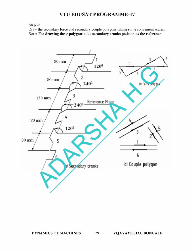
Step 2:
Draw the secondary force and secondary couple polygons taking some convenient scales.
Note: For drawing these polygons take secondary cranks position as the reference
Note: No secondary unbalanced force or couple
ADARSHA H G
VTU EDUSAT PROGRAMME-17
DYNAMICS OF MACHINES VIJAYAVITHAL BONGALE
30
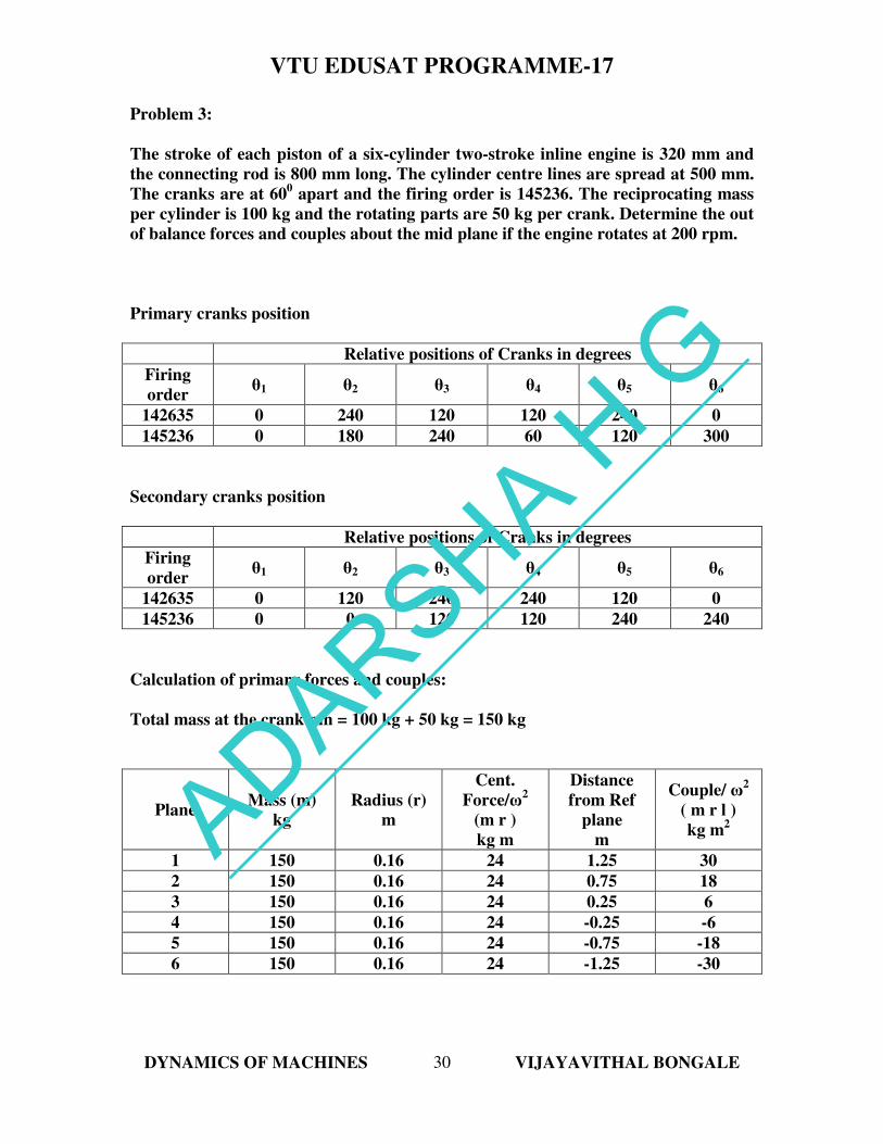
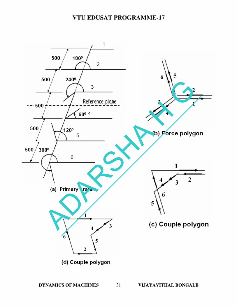
Problem 3:
The stroke of each piston of a six-cylinder two-stroke inline engine is 320 mm and
the connecting rod is 800 mm long. The cylinder centre lines are spread at 500 mm.
The cranks are at 600 apart and the firing order is 145236. The reciprocating mass
per cylinder is 100 kg and the rotating parts are 50 kg per crank. Determine the out
of balance forces and couples about the mid plane if the engine rotates at 200 rpm.
Primary cranks position
Relative positions of Cranks in degrees
Firing
order θ1 θ2 θ3 θ4 θ5 θ6
142635 0 240 120 120 240 0
145236 0 180 240 60 120 300
Secondary cranks position
Relative positions of Cranks in degrees
Firing
order θ1 θ2 θ3 θ4 θ5 θ6
142635 0 120 240 240 120 0
145236 0 0 120 120 240 240
Calculation of primary forces and couples:
Total mass at the crank pin = 100 kg + 50 kg = 150 kg
Plane Mass (m)
kg
Radius (r)
m
Cent.
Force/ω2
(m r )
kg m
Distance
from Ref
plane
m
Couple/ ω2
( m r l )
kg m2
1 150 0.16 24 1.25 30
2 150 0.16 24 0.75 18
3 150 0.16 24 0.25 6
4 150 0.16 24 -0.25 -6
5 150 0.16 24 -0.75 -18
6 150 0.16 24 -1.25 -30
ADARSHA H G
VTU EDUSAT PROGRAMME-17
DYNAMICS OF MACHINES VIJAYAVITHAL BONGALE
31
ADARSHA H G
VTU EDUSAT PROGRAMME-17
DYNAMICS OF MACHINES VIJAYAVITHAL BONGALE
32
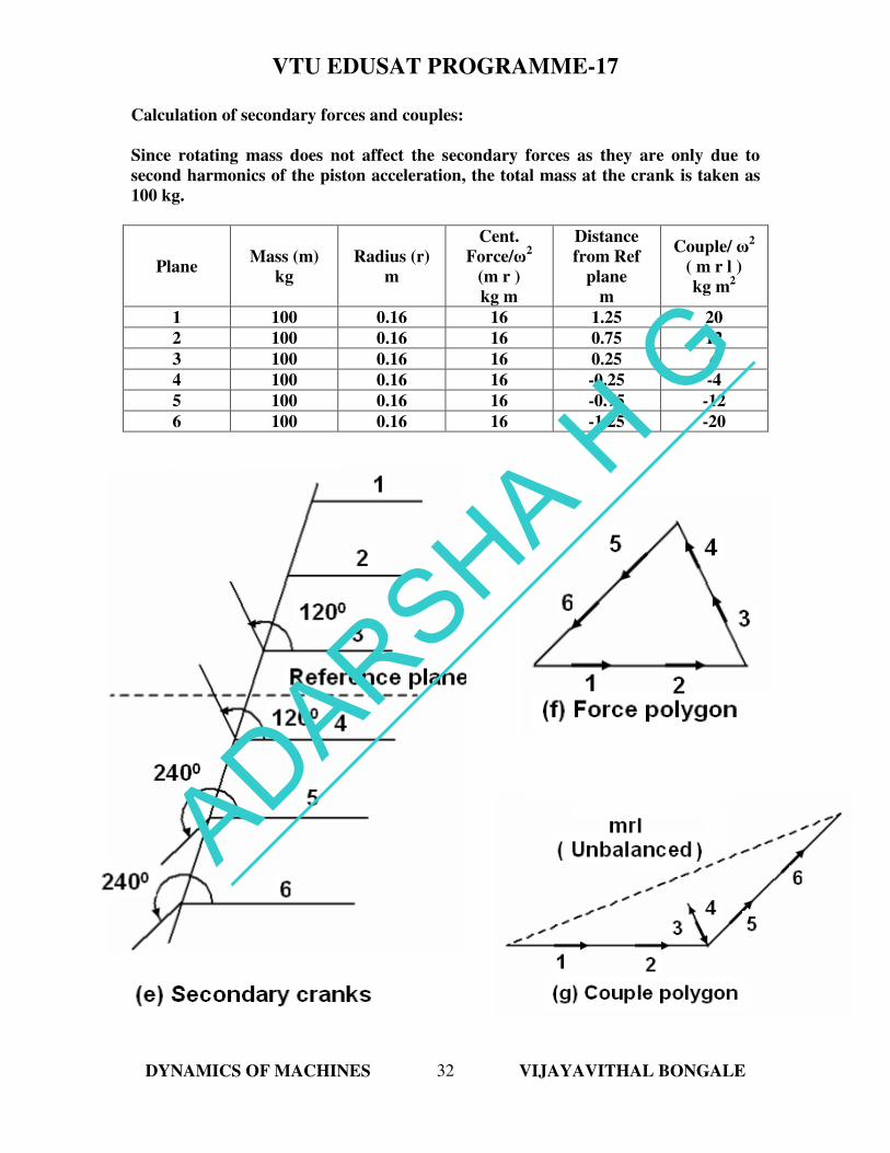
Calculation of secondary forces and couples:
Since rotating mass does not affect the secondary forces as they are only due to
second harmonics of the piston acceleration, the total mass at the crank is taken as
100 kg.
Plane Mass (m)
kg
Radius (r)
m
Cent.
Force/ω2
(m r )
kg m
Distance
from Ref
plane
m
Couple/ ω2
( m r l )
kg m2
1 100 0.16 16 1.25 20
2 100 0.16 16 0.75 12
3 100 0.16 16 0.25 4
4 100 0.16 16 -0.25 -4
5 100 0.16 16 -0.75 -12
6 100 0.16 16 -1.25 -20
ADARSHA H G
VTU EDUSAT PROGRAMME-17
DYNAMICS OF MACHINES VIJAYAVITHAL BONGALE
33
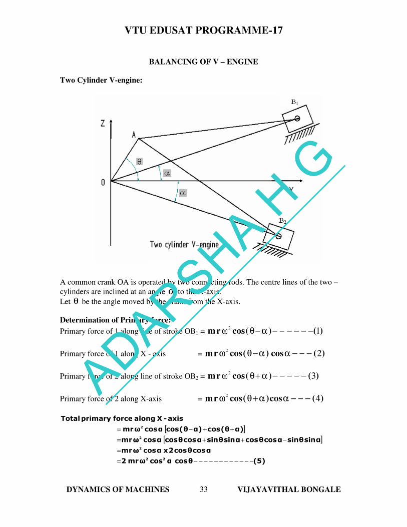
BALANCING OF V – ENGINE
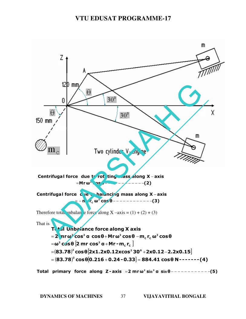
Two Cylinder V-engine:
A common crank OA is operated by two connecting rods. The centre lines of the two –
cylinders are inclined at an angle α to the X-axis.
Let θ be the angle moved by the crank from the X-axis.
Determination of Primary force:
Primary force of 1 along line of stroke OB1 = )()(cosrm 12
−−−−−−α−θω
Primary force of 1 along X - axis = )(cos)(cosrm 22
−−−αα−θω
Primary force of 2 along line of stroke OB2 = )()(cosrm 32
−−−−−α+θω
Primary force of 2 along X-axis = )(cos)(cosrm 42
−−−αα+θω
[ ]
[ ]
(5)θcosαcosωrm2
αcosθcos2xαcosωrm
αsinθsinαcosθcosαsinθsinαcosθcosαcosωrm
)αθ(cos)αθ(cosαcosωrm
axis-X along force primary Total
22
2
2
2
−−−−−−−−−−−−=
=
−++=
++−=
ADARSHA H G
VTU EDUSAT PROGRAMME-17
DYNAMICS OF MACHINES VIJAYAVITHAL BONGALE
34
Similarly,
[ ]
[ ]
(6)θsinαsinωrm2
αsinθsin2xαsinωrm
αsinθsinαcosθcos(α)sinθsinαcosθ(cosαsinωrm
α)sinαθ(cos-αsin)αθ(cosωrm
axis-Z along force primary Total
22
2
2
2
−−−−−−−−−−−−=
=
−−+=
+−=
( ) ( )
( ) ( ) (7)θsinαsinθcosαcosωrm2
θsinαsinωrm2θcosαcosωrm2
force Primary Resultant
22222
222222
−−−−−+=
+=
and this resultant primary force will be at angle β with the X – axis, given by,
(8)θcosαcos
θsinαsinβtan
2
2
−−−−−−=
If0
902 =α , the resultant force will be equal to
( ) ( )
(9)ωrm
θsin45sinθcos45cosωrm22
2022022
−−−−−=
+
and (10)θtanθcos45cos
θsin45sinβtan
02
02
−−−−−−==
i.e., θβ = or it acts along the crank and therefore, can be completely balanced by a
mass at a suitable radius diametrically opposite to the crank, such that,
(11)----- rmrmrr
=
For a given value of α, the resultant force is maximum (Primary force), when
( ) ( )
( ) maximumisθsinαsinθcosαcos
or
maximumisθsinαsinθcosαcos
2424
2222
+
+
ADARSHA H G
VTU EDUSAT PROGRAMME-17
DYNAMICS OF MACHINES VIJAYAVITHAL BONGALE
35
Or
( )
0θcosθsin2xαsinθsinθcos2xαcos-i.e.,
0θsinαsinθcosαcosdθ
d
44
2424
=+
=+
[ ] 0αcos-αsinθ2sin i.e.,
0θ2sinxαsinθ2sinxαcos- i.e.,44
44
=
=+
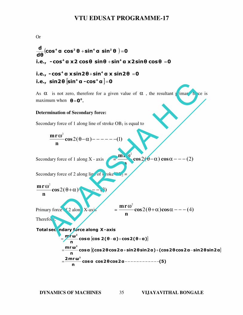
As α is not zero, therefore for a given value of α , the resultant primary force is
maximum when .00θ=
Determination of Secondary force:
Secondary force of 1 along line of stroke OB1 is equal to
)()(cosn
rm12
2
−−−−−−α−θω
Secondary force of 1 along X - axis = )(cos)(cosn
rm22
2
−−−αα−θω
Secondary force of 2 along line of stroke OB2 =
)()(cosn
rm32
2
−−−−−α+θω
Primary force of 2 along X-axis = )(cos)(cosn
rm42
2
−−−αα+θω
Therefore,
[ ]
[ ]
(5)α2cosθ2cosαcosn
ωrm2
α2sinθ2sinα2cosθ2(cos)α2sinθ2sinα2cosθ2(cosαcosn
ωrm
)αθ(2cos)αθ(2cosαcosn
ωrm
axis-X along force secondary Total
2
2
2
−−−−−−−−−−−−=
−++=
++−=
ADARSHA H G
VTU EDUSAT PROGRAMME-17
DYNAMICS OF MACHINES VIJAYAVITHAL BONGALE
36
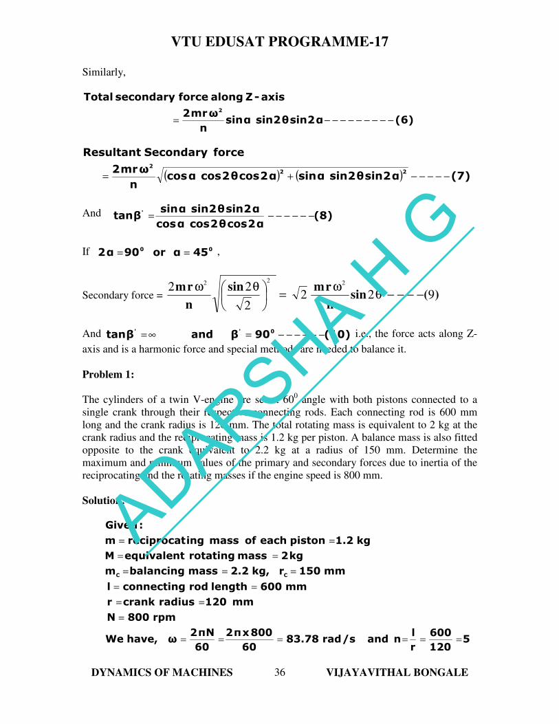
Similarly,
(6)α2sinθ2sinαsinn
ωrm2
axis-Z along force secondary Total2
−−−−−−−−−=
( ) ( ) (7)α2sinθ2sinαsinα2cosθ2cosαcosn
ωrm2
force Secondary Resultant
222
−−−−−+=
And (8)α2cosθ2cosαcos
α2sinθ2sinαsinβtan '
−−−−−−=
If 00 45αor90α2 == ,
Secondary force = )(sinn
rmsin
n
rm922
2
22 222
−−−−θω
=
θω
And (10)90βandβtan 0''−−−−−−=∞= i.e., the force acts along Z-
axis and is a harmonic force and special methods are needed to balance it.
Problem 1:
The cylinders of a twin V-engine are set at 600 angle with both pistons connected to a
single crank through their respective connecting rods. Each connecting rod is 600 mm
long and the crank radius is 120 mm. The total rotating mass is equivalent to 2 kg at the
crank radius and the reciprocating mass is 1.2 kg per piston. A balance mass is also fitted
opposite to the crank equivalent to 2.2 kg at a radius of 150 mm. Determine the
maximum and minimum values of the primary and secondary forces due to inertia of the
reciprocating and the rotating masses if the engine speed is 800 mm.
Solution:
5120
600
r
lnand/srad83.78
60
800xπ2
60
Nπ2ωhave,We
rpm800N
mm120radiuscrankr
mm600lengthrodconnectingl
mm150rkg,2.2massbalancingm
kg2 mass rotatingequivalentM
kg1.2pistoneachofmassingreciprocatm
:Given
CC
======
=
==
==
===
==
==
ADARSHA H G
VTU EDUSAT PROGRAMME-17
DYNAMICS OF MACHINES VIJAYAVITHAL BONGALE
37
Primary Force:
(1)θcosαcosωrm2axis-X along force primary Total 22
−−−−−−−−−−−−=
(2)θcosωrM
axisXalongmassrotatingtodue forcelCentrifuga2
−−−−−−−−−−−−=
−
(3)θcosωrm
axisXalongmassbalancingtodue forcelCentrifuga2
CC −−−−−−−−−−−−−=
−
Therefore total unbalance force along X –axis = (1) + (2) + (3)
That is
[ ]
( ) [ ]
( ) [ ] (4)-------Nθcos884.410.33-0.240.216θcos83.78
2.2x0.152x0.1230xcos2x1.2x0.12θcos83.78
rm-rMαcosrm2θcosω
θcosωrmθcosωrMθcosαcosωrm2
axis X along force UnbalanceTotal
2
022
CC
22
2
CC
222
=+=
−+=
+=
−+=
(5)θsαsωrm2axis-Z along force primary Total 22
−−−−−−−−−−−−= inin
ADARSHA H G
VTU EDUSAT PROGRAMME-17
DYNAMICS OF MACHINES VIJAYAVITHAL BONGALE
38
(6)θsωrM
axisZalongmassrotatingtodue forcelCentrifuga2
−−−−−−−−−−−−=
−
in
(7)θsωrm
axisZalongmassbalancingtodue forcelCentrifuga2
CC −−−−−−−−−−−−−=
−
in
Therefore total unbalance force along Z –axis = (5) + (6) + (7)
That is
[ ]
( ) [ ]
( ) [ ] (8)-------Nθsin126.34-0.33-0.240.072θsin83.78
2.2x0.152x0.1230xsin2x1.2x0.12θsin83.78
rm-rMαsinrm2θsinω
θsinωrmθsinωrMθsinαsinωrm2
axis -Z along force UnbalanceTotal
2
022
CC
22
2
CC
222
=+=
−+=
+=
−+=
( ) ( )
(9)15961.8θcos766219.25
θsin15961.8θcos782181.05
θsin126.34-θcos884.41
force Primary Resultant
2
22
22
−−−−−+=
+=
+=
This is maximum, when 0
0=θ and minimum, when 0
90=θ
(11)N126.3415961.890cos766219.25
90θwhen i.e., force, Primary MinimumAnd
(10)N884.4115961.8766219.25
0θwhen i.e., force, Primary Maximum
02
0
0
−−−−−=+=
=
−−−−−=+=
=
Secondary force:
The rotating masses do not affect the secondary forces as they are only due to second
harmonics of the piston acceleration.
ADARSHA H G
VTU EDUSAT PROGRAMME-17
DYNAMICS OF MACHINES VIJAYAVITHAL BONGALE
39
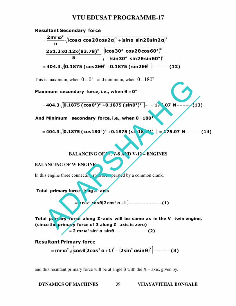
( ) ( )
( )
( )
[ ] (12)2θθsin(0.18752θθcos(0.1875404.3
60sinθ2sin30sin
60cosθ2cos30cos
5
78)x0.12x(83.x1.22
α2sinθ2sinαsinα2cosθ2cosαcosn
ωrm2
force Secondary Resultant
22
200
2222
222
−−−−−+=
+=
+=
This is maximum, when 0
0=θ and minimum, when 0
180=θ
[ ]
[ ] (14)N175.07)018sin(0.1875)180cos(0.1875404.3
180θwhen i.e., force, secondary MinimumAnd
(13)N175.07)0sin(0.1875)0cos(0.1875404.3
0θwhen i.e., force, secondary Maximum
2020
0
2020
0
−−−−−=+=
=
−−−−−=−+=
=
BALANCING OF W, V-8 AND V-12 – ENGINES
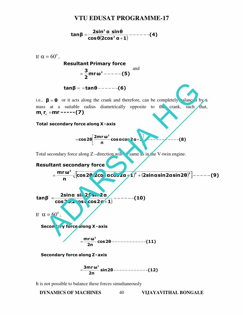
BALANCING OF W ENGINE
In this engine three connecting rods are operated by a common crank.
( ) (1)1 αcos2θcosωrm
axis-X along force primary Total
22−−−−−−−−−−−−+=
(2)θsinαsinωrm2
zero)isaxisZalong3offorceprimarythe(since
engine,twinVtheinsasamebewillaxis-Z along force primary Total
22−−−−−−−−−−−−=
−
−
( ) ( )[ ] (3)θαsin2sin1α2cosθcosωrm
force Primary Resultant
22222−−−−−++=
and this resultant primary force will be at angle β with the X – axis, given by,
ADARSHA H G
VTU EDUSAT PROGRAMME-17
DYNAMICS OF MACHINES VIJAYAVITHAL BONGALE
40
( )
(4)1α2cosθcos
θsinα2sinβtan
2
2
−−−−−−+
=
If 0
60=α ,
(5)ωrm
2
3
force Primary Resultant
2−−−−−=
and
(6)θtanβtan −−−−−−==
i.e., θβ = or it acts along the crank and therefore, can be completely balanced by a
mass at a suitable radius diametrically opposite to the crank, such that,
(7)----- rmrmrr
=
(8)1α2cosαcosn
ωr2m2θcos
axis-X along force secondary Total
2
−−−−−−−−−−−−
+=
Total secondary force along Z –direction will be same as in the V-twin engine.
( ) ( )[ ] (9)2θsin2αsinα2sin12αcosα2cos2θcosn
ωrm
force secondary Resultant
222
−−−−−++=
( )(10)
1α2cosα2cosθ2cos
α2sinθ2sinα2sinβtan '
−−−−−−+
=
If 0
60=α ,
(11)2θcos2n
ωrm
axis-X along force Secondary
2
−−−−−−−−−−−−=
(12)2θsin2n
ωr3m
axis-Z along force Secondary
2
−−−−−−−−−−−−=
It is not possible to balance these forces simultaneously
ADARSHA H G
VTU EDUSAT PROGRAMME-17
DYNAMICS OF MACHINES VIJAYAVITHAL BONGALE
41
V-8 ENGINE
It consists of two banks of four cylinders each. The two banks are inclined to each other
in the shape of V. The analysis will depend on the arrangement of cylinders in each bank.
V-12 ENGINE
It consists of two banks of six cylinders each. The two banks are inclined to each other in
the shape of V. The analysis will depend on the arrangement of cylinders in each bank.
If the cranks of the six cylinders on one bank are arranged like the completely balanced
six cylinder, four stroke engine then, there is no unbalanced force or couple and thus the
engine is completely balanced.
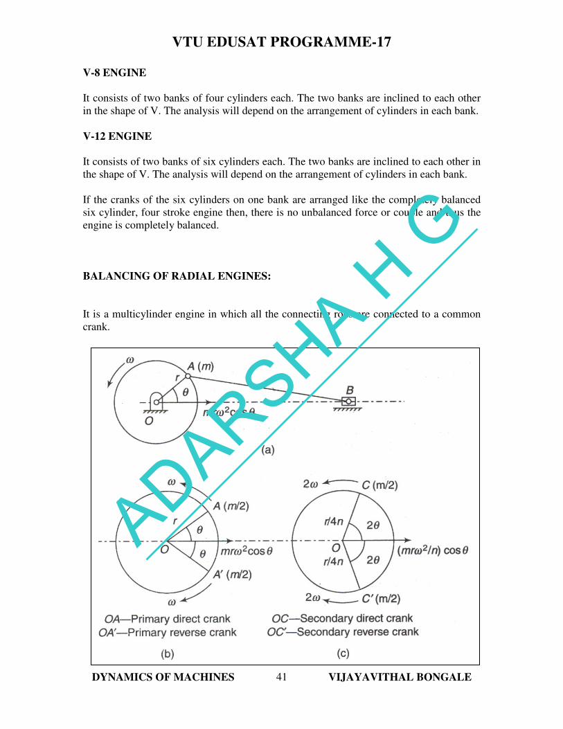
BALANCING OF RADIAL ENGINES:
It is a multicylinder engine in which all the connecting rods are connected to a common
crank.
ADARSHA H G
VTU EDUSAT PROGRAMME-17
DYNAMICS OF MACHINES VIJAYAVITHAL BONGALE
42
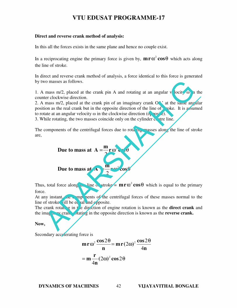
Direct and reverse crank method of analysis:
In this all the forces exists in the same plane and hence no couple exist.
In a reciprocating engine the primary force is given by, θω cosrm2
which acts along
the line of stroke.
In direct and reverse crank method of analysis, a force identical to this force is generated
by two masses as follows.
1. A mass m/2, placed at the crank pin A and rotating at an angular velocity ω in the
counter clockwise direction.
2. A mass m/2, placed at the crank pin of an imaginary crank OA’ at the same angular
position as the real crank but in the opposite direction of the line of stroke. It is assumed
to rotate at an angular velocity ω in the clockwise direction (opposite).
3. While rotating, the two masses coincide only on the cylinder centre line.
The components of the centrifugal forces due to rotating masses along the line of stroke
are,
θω= cosrm
AatmasstoDue2
2
θω= cosrm
AatmasstoDue' 2
2
Thus, total force along the line of stroke = θω cosrm2
which is equal to the primary
force.
At any instant, the components of the centrifugal forces of these masses normal to the
line of stroke will be equal and opposite.
The crank rotating in the direction of engine rotation is known as the direct crank and
the imaginary crank rotating in the opposite direction is known as the reverse crank.
Now,
Secondary accelerating force is
θω=
θω=
θω
224
4
22
2
2
22
cos)(n
rm
n
cos)(rm
n
cosrm
ADARSHA H G
VTU EDUSAT PROGRAMME-17
DYNAMICS OF MACHINES VIJAYAVITHAL BONGALE
43
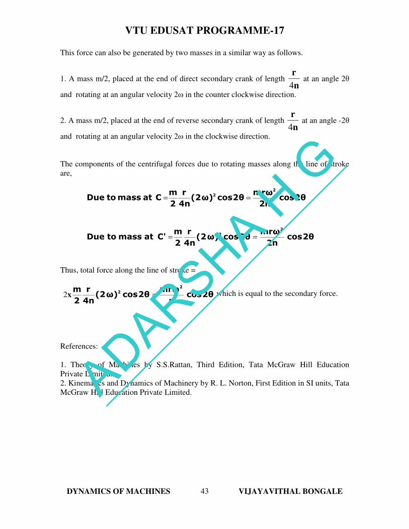
This force can also be generated by two masses in a similar way as follows.
1. A mass m/2, placed at the end of direct secondary crank of length n
r
4 at an angle 2θ
and rotating at an angular velocity 2ω in the counter clockwise direction.
2. A mass m/2, placed at the end of reverse secondary crank of length n
r
4 at an angle -2θ
and rotating at an angular velocity 2ω in the clockwise direction.
The components of the centrifugal forces due to rotating masses along the line of stroke
are,
2θcos2n
mrω2θcosω)(2
4n
r
2
mCatmasstoDue
2
2==
2θcos2n
mrω2θcosω)(2
4n
r
2
mC'atmasstoDue
2
2==
Thus, total force along the line of stroke =
2θcosn
mrω2θcosω)(2
4n
r
2
m 2
2=x2 which is equal to the secondary force.
References:
1. Theory of Machines by S.S.Rattan, Third Edition, Tata McGraw Hill Education
Private Limited.
2. Kinematics and Dynamics of Machinery by R. L. Norton, First Edition in SI units, Tata
McGraw Hill Education Private Limited.
ADARSHA H
G