Balancing, and Its Effects on Vibration Response By Victor ... · Balancing, and Its Effects on...
9
Balancing, and Its Effects on Vibration Response By Victor Wowk, P.E. If I ever came across a perfectly balanced rotor, I would: 1. Think that I died and went to heaven, and 2. Not know it, because perfect balance is unmeasurable since it does not create any vibration. Unbalance is a defect on the rotating part that creates an unbalanced centrifugal force that transmits into the stationary structure as an oscillating motion. We cannot directly measure the unbalance on the rotor, nor the centrifugal force that it creates. What we can measure is oscillating motion on the stationary structure. Forces, especially the oscillating ones, are what does damage to mechanical parts. Since we can only measure oscillating motion, we tend to make judgments about damage potential based on the measured motion alone. The vibration motion measured at a point on the stationary structure depends not only on the centrifugal force itself, but on the machine size and configuration, the bearings, the stiffness of the support structure, and whether resonance is an active player. This article will discuss all of these factors. The vibration analyst is not only a data gatherer and a messenger, but also a judge. He/she must interpret the evidence, giving due consideration to all the factors that influence the measured data, then assess the damage risk. Forces and Motion A pure unbalance creates a centrifugal force that is radial, and is well defined by the formula: (1) F c = mr 2 F c is the peak force m is the imaginary mass r is the radius of the imaginary mass ω is the rotating speed in radians per second We use the concept of an imaginary mass for unbalance because we do not always know the exact cause for each specific rotor. It could be caused by nonuniform material density (porosity), or eccentricity from poor fits. When we place the correction weight, then the mass and radius of the correction weight becomes 180 ° opposite from this imaginary mass. Consistent units should be used in equation (1) with the appropriate conversion factors. In English units, the formula is― (2) F Lb f = 1.77 oz∗in rpm 1,000 2 This formula can also be presented graphically as in Figure 1.
Transcript of Balancing, and Its Effects on Vibration Response By Victor ... · Balancing, and Its Effects on...

Balancing, and Its Effects on Vibration ResponseBy Victor Wowk, P.E.
If I ever came across a perfectly balanced rotor, I would:
1. Think that I died and went to heaven, and2. Not know it, because perfect balance is unmeasurable since it does not create any
vibration.
Unbalance is a defect on the rotating part that creates an unbalanced centrifugal force that transmits into the stationary structure as an oscillating motion. We cannot directly measure the unbalance on the rotor, nor the centrifugal force that it creates. What we can measure is oscillating motion on the stationary structure.
Forces, especially the oscillating ones, are what does damage to mechanical parts. Since we canonly measure oscillating motion, we tend to make judgments about damage potential based on the measured motion alone. The vibration motion measured at a point on the stationary structure depends not only on the centrifugal force itself, but on the machine size and configuration, the bearings, the stiffness of the support structure, and whether resonance is an active player. This article will discuss allof these factors. The vibration analyst is not only a data gatherer and a messenger, but also a judge. He/she must interpret the evidence, giving due consideration to all the factors that influence the measured data, then assess the damage risk.
Forces and Motion
A pure unbalance creates a centrifugal force that is radial, and is well defined by the formula:
(1) Fc = mr2 Fc is the peak force m is the imaginary mass r is the radius of the imaginary mass ω is the rotating speed in radians per second
We use the concept of an imaginary mass for unbalance because we do not always know the exact cause for each specific rotor. It could be caused by nonuniform material density (porosity), or eccentricity from poor fits. When we place the correction weight, then the mass and radius of the correction weight becomes 180 ° opposite from this imaginary mass.
Consistent units should be used in equation (1) with the appropriate conversion factors. In English units, the formula is―
(2) FLbf
= 1.77 oz∗in rpm1,000
2
This formula can also be presented graphically as in Figure 1.

This centrifugal force from the imaginary heavy-spot is only one of many, since every small piece of the rotor creates its own centrifugal force. The majority of these forces are countered by equal masses and forces on the other side of the rotating center. These forces are constant and balanced. They stretch the rotor outward and cause a circumferential tangential stress at the inner diameter. If therotor is accelerated in speed, the stress will grow until it causes cracking at the inner diameter that propagates outward and the rotor flies apart. This is called the burst speed, and there are test facilities that do just that in a containment structure that captures these exploding parts. Engineers use a healthy safety factor of 4x to 10x and define that as the maximum safe speed. These constant, and balanced, centrifugal forces are mostly undetectable (except for strain gages mounted on the rotor and transmittedout), so we generally are unaware of them until the rotor separates. The unbalance centrifugal force from the imaginary heavy spot, however, is another story (Figure 2).
The unbalanced centrifugal force has two effects:
1. It will distort the rotor.2. It will couple into the stationary structure as an oscillation at the frequency of rotation.
Figure 1

The unbalanced force is also a constant force on the rotating frame of reference. It will grow once during spin-up to its maximum, remain constant during rotation at constant speed, then decline during coast-down. But since it is unbalanced, it rotates around 360°. The bearing is the coupling device between the rotating and stationary parts. The bearing transmits the rotating heavy spot force to the stationary structure, where it becomes an oscillating force. The bearing gets beat up in the process. The oscillating forces on the stationary structure causes an oscillating motion that depends on the stiffness of the structure. Since it is motion, now we can measure something. The centrifugal forces are created on the rotating part where the defect is, but the damaging forces are felt at the bearings and the stationary structure.
We could measure the heavy spot force with a weighing scale, if the scale was fast enough in response, or the rotor turned slow enough. The scale would display a sinusoidal alternating reading riding on top of a constant weight. The vibration transducer functions like a fast electronic scale reading of the oscillating force alone, being unresponsive to the constant force. The vibration transducer does not actually measure force, but rather motion. With the measured motion, I could estimate the force causing this motion if I know something about the mass of the rotor, or the stiffness of the supports.
If I measure motion with a proximity probe, then I measure eccentricity of the shaft centerline directly, assuming low runout or proper compensation for runout with a slow-roll check. With this eccentricity measure and knowledge of the rotor weight, then I can calculate the unbalance using the fundamental unbalance equation:
(3) U = Me U = UnbalanceM = Mass of rotor
e = Measured eccentricity
Figure 2

The calculated unbalance can then be plugged into equation (1) or (2), along with a speed measurement, to calculate the peak centrifugal force. Forces on machine elements are what causes damage, not motion.
If I measured motion with an accelerometer, which is the most common motion sensor for vibration today, then I can calculate the force from Newton's Second Law:
(4) F = ma F = force m = mass a = acceleration
I would need to estimate the mass in motion, which is no easy task for a support structure boltedto a concrete foundation since it also has significant stiffness. For a spring-isolated machine, the estimated mass in motion is all the mass above the springs. If desired, the unbalance itself can be calculated by combining equations (1) and (4)
(5) U =Ma
2 U is the unbalance
M is the mass in motion a is the acceleration ω is the circular speed in radians per second
Fortunately, there is an easier way to estimate damage risk with acceleration measurements, thatwill be presented later.
Machine Size and Configuration
A large and heavy rotor is going to be relatively insensitive to unbalance just by virtue of its inertia. Eccentricity, e, is defined in ANSI S2.41 to be numerically identical to specific unbalance, lb-in of unbalance per pound of rotor weight. This is an interesting philosophical concept. It says explicitly than unbalance and manufacturing variability are inseparable, because eccentricity is determined by manufacturing processes of drilling on center, turning round and concentric, and assembly tolerances. For our discussion here, this equality states that a heavy rotor can accumulate more heavy-spot mass before the rotor is pulled off the center of rotation a specified amount. This has implications for the machine designer who must accommodate a certain amount of material buildup, such as in a centrifuge, and not over vibrate. A heavier rotor would preform better in that application, because it would be less sensitive to material buildup.
This also explains why we spend so much effort balancing fans. They are light, high-speed rotors, many times mounted on soft supports. This makes them sensitive to small unbalances, which create large motion.
The centrifugal force due to unbalance is supposed to be a purely radial force. It is mostly radial on center suspended and symmetrical narrow rotors. Overhung rotors will couple this radial force into the axial direction depending on the amount of overhang, the position of the center of gravityof the rotating system, and the spacing between bearings. In other words, we can get significant axial motion from unbalance depending on the machine configuration. Bearings do not tolerate axial forces well. High axial motion at synchronous speed will always get my attention because it kills bearings.

Bearings
Unbalance does not pose serious consequences for rotors themselves, but rather the componentssurrounding the rotor. Rolling-element bearings are the most chronic casualty. Rolling-element bearings have small radial and axial clearance, and when this clearance is exhausted by the unbalance eccentricity, then the rollers press through the hydraulic lift provided by grease or oil, and encounter a hard limit. The local contact forces in the bearing translate into very high stresses because of the small contact area, especially in ball bearings. The surfaces in contact suffer fatigue damage, and cracking, or spalling, ensue. The rolling-element bearings, being rigid, also transmit these unbalance forces well to the surrounding structure.
Plain bearings, on the other hand, tolerate unbalance better. The shaft journal has a clearance to wiggle around inside the bearing and is also cushioned by a thicker oil film. Plain bearing machines are smother and quieter for the same unbalance forces. The general rule for concern is that when the shaft motion, as measured with a proximity probe, approaches ½ of the radial clearance, then there is a risk of rubbing.
There is a very good design solution to obviate the damage to bearings from unbalance, especially rolling element bearings. The solution is compliant bearings. The obvious example is wheelbearings on vehicles. These are rigid, rolling-element bearings that are compliant mounted, with springs on one side and rubber on the other. They are exposed to gross unbalances, in addition to severe road shocks, and still survive to a normal old age.
Support Structure
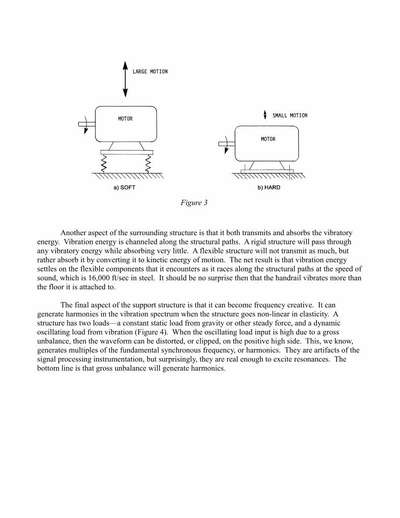
The structure surrounding a machine is a major factor defining both vibratory motion and damage. The two are related, sometimes in a reciprocal manner. Figure 3 will illustrate the concept. There are two identical motors with the same internal unbalance. One is mounted on springs in (a) and the other is hard bolted to a concrete floor in (b). The soft supported motor will have more motion but the bearings will have smaller contact forces at the rollers. The hard bolted motor will have less vibratory motion but high contact forces in the bearings. So here is a contradictory situation to common wisdom where more motion is better, and less motions leads to early failure. This is why vibration analysis remains a human function with a high level of judgment.
Another aspect of the surrounding structure is that it both transmits and absorbs the vibratory energy. Vibration energy is channeled along the structural paths. A rigid structure will pass through any vibratory energy while absorbing very little. A flexible structure will not transmit as much, but rather absorb it by converting it to kinetic energy of motion. The net result is that vibration energy settles on the flexible components that it encounters as it races along the structural paths at the speed ofsound, which is 16,000 ft/sec in steel. It should be no surprise then that the handrail vibrates more thanthe floor it is attached to.
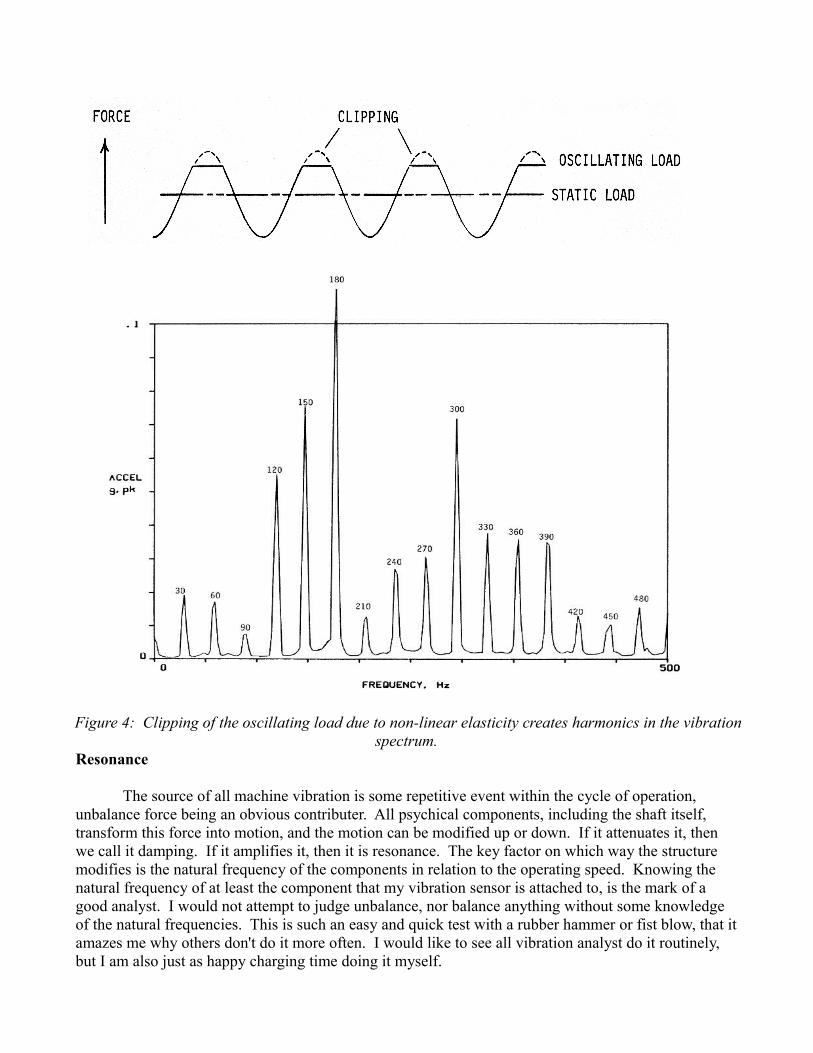
The final aspect of the support structure is that it can become frequency creative. It can generate harmonies in the vibration spectrum when the structure goes non-linear in elasticity. A structure has two loads—a constant static load from gravity or other steady force, and a dynamic oscillating load from vibration (Figure 4). When the oscillating load input is high due to a gross unbalance, then the waveform can be distorted, or clipped, on the positive high side. This, we know, generates multiples of the fundamental synchronous frequency, or harmonics. They are artifacts of the signal processing instrumentation, but surprisingly, they are real enough to excite resonances. The bottom line is that gross unbalance will generate harmonics.
Figure 3
Resonance
The source of all machine vibration is some repetitive event within the cycle of operation, unbalance force being an obvious contributer. All psychical components, including the shaft itself, transform this force into motion, and the motion can be modified up or down. If it attenuates it, then we call it damping. If it amplifies it, then it is resonance. The key factor on which way the structure modifies is the natural frequency of the components in relation to the operating speed. Knowing the natural frequency of at least the component that my vibration sensor is attached to, is the mark of a good analyst. I would not attempt to judge unbalance, nor balance anything without some knowledge of the natural frequencies. This is such an easy and quick test with a rubber hammer or fist blow, that itamazes me why others don't do it more often. I would like to see all vibration analyst do it routinely, but I am also just as happy charging time doing it myself.
Figure 4: Clipping of the oscillating load due to non-linear elasticity creates harmonics in the vibrationspectrum.

When the structure is actively amplifying the unbalance force, the resulting vibration will be very large and the structure will suffer fatigue damage. But resonance is not always bad. We have resonance machines in the form of watches, musical instruments, and sensors. Resonance on a panel that makes a lot of noise may be irritating, but of little consequence. A machine on springs resonating at the natural frequency of the springs can do this until the 23rd century and I don't care. This is like your car shaking on its springs on a windy day. The key questions to ask are:
1. Where is the source of energy?2. Where is the vibration energy dissipated?3. What is the force transmission path?
This type of interpretation of the measured motion takes us to the highest level of vibration analysis.
On a flexible rotor, where the shaft resonates at its critical speed, the shaft suffers fatigue damage because there is reversed bending of the shaft.
Damage Risk
All machines vibrate during operation as a normal consequence of being alive and doing work. The question that everyone likes answered is how much is normal, and at what level do we call it bad. There are industry guidelines on balance levels that are based on experience, and most of these are valid and good criteria to start from. The basic premise of these guidelines are that there is a balance level that is economically achievable and will not cause premature wear. So they are fair to bothsides—the machine builder and the customer. The machine builder only has control of the balance level, the bearings, and the fits if the machine is fully assembled at the factory. The machine builder has no control of the site conditions, which are the support structure. The support structure, we know, can modify the motion measured from small unbalances. So what is a vibration analyst to do with higher than normal amplitude at rotating speeds? Here are some suggestions:
1. Look at the overall pattern at each bearing in all three orthogonal directions. This can tell us something about the flexibility of the structure, and whether resonance is active, because resonance is strongly directional.
2. Stop the machine and measure the natural frequencies of the major components and structural parts.
3. Don't get too excited if there is a large unbalance. Unbalance is not serious enough for immediate repair. Machines have operated for many years with unbalance levels above industryguidelines, even 2 to 5x the acceptable levels. What unbalance will do is beat-up the bearings and transmit elsewhere to do collateral damage.
4. Do get excited if:a) There is high axial motion.b) The bearings are generating large shock pulses.c) There are harmonics in the spectrum.d) There is structural cracking.e) Controls malfunction.f) The operator complains of numbness in the hands.

Generally, we would like the dynamic oscillating forces to be less than 10-percent of the rotor weight. This is the old 10-percent rule, and there is even a formula to calculate the test weight for balancing that will generate a centrifugal force of 10 percent. It is:
(6) Ur = 56,347 Wrpm
2 W = journal weight, Lb
Ur = residual unbalance, oz·in
If I were measuring unbalance in acceleration units, then 0.1 g is very close to the 10-percent rule. So I would like to see everything balanced to 0.1 g or less, but not zero. Zero unbalance is not achievable. There will always be some residual unbalance. There is no such thing as perfect balance on this side of the galaxy, just like there is no perfect woman nor perfect man.
Victor Wowk, P.E., is the president of Machine Dynamics, Inc., based in Albuquerque. He is the authorof Machinery Vibration: Balancing, published in 1995 by McGraw-Hill. He teaches a two-day balancing seminar. Schedules are posted at www.machinedyn.com.