Balance: The Key to Success!engineering.nyu.edu/mechatronics/Control_Lab/Criag/Craig_RPI/2002/...The...
45
Mechatronics Dynamic System Investigation K. Craig 1 Dynamic System Investigation Process • Dynamic System Investigation Overview • Stages of a Dynamic System Investigation – Balance: The Key to Success! • Dynamic System Examples • Dynamic System Investigation Case Study
Transcript of Balance: The Key to Success!engineering.nyu.edu/mechatronics/Control_Lab/Criag/Craig_RPI/2002/...The...

MechatronicsDynamic System Investigation
K. Craig1
Dynamic System Investigation Process
• Dynamic System Investigation Overview• Stages of a Dynamic System Investigation
– Balance: The Key to Success!• Dynamic System Examples• Dynamic System Investigation Case Study

MechatronicsDynamic System Investigation
K. Craig2
Dynamic System Investigation
PhysicalSystem
PhysicalModel
MathematicalModel
ExperimentalAnalysis Comparison Mathematical
Analysis
DesignChanges

MechatronicsDynamic System Investigation
K. Craig3
P h y s ic a lS y s t e m
P h y s ic a lM o d e l
M a t hM o d e l
M o d e lP a r a m e t e r
I D
A c t u a lD y n a m icB e h a v io r
C om p a r eP r e d ic t e dD y n a m icB e h a v io r
M a k eD e s ig n
D e c is io n s
D e s ig nC o m p le t e
Measurements,Calculations,
Manufacturer's Specifications
Assumptionsand
Engineering Judgement
Physical Laws
ExperimentalAnalysis
Equation Solution:Analytical
and NumericalSolution
Model Adequate,Performance Adequate
Model Adequate,Performance Inadequate
Modify or
Augment
Model Inadequate:Modify
D y n a m ic S y s t e m I n v e s t ig a t io n
Which Parameters to Identify?What Tests to Perform?

MechatronicsDynamic System Investigation
K. Craig4
Dynamic System Investigation Overview
• Apply the steps in the process when:– An actual physical system exists and one desires to
understand and predict its behavior.– The physical system is a concept in the design process
that needs to be analyzed and evaluated.
• After recognizing a need for a new product or service, one generates design concepts by using:– Past experience (personal and vicarious)– Awareness of existing hardware– Understanding of physical laws– Creativity

MechatronicsDynamic System Investigation
K. Craig5
• The importance of modeling and analysis in the design process has never been more important.
• Design concepts can no longer be evaluated by the build-and-test approach because it is too costly and time consuming.
• Validating the predicted dynamic behavior in this case, when no actual physical system exists, then becomes even more dependent on one's past hardware and experimental experience.

MechatronicsDynamic System Investigation
K. Craig6
Do you ever feel like this?
Integrated Design Concept
Build&
Test
Model,Analyze &
Predict
Electronics
Controls
Computers
Mechanical
Sensors Actuators
EngineeringProblem
Systematic, StructuredApproach to Design
YES! NO!
?Cost-Effective, High-Quality,Timely, Robust Design
MechatronicsDynamic System Investigation
K. Craig7
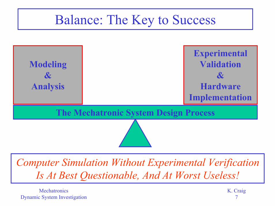
Balance: The Key to Success
Experimental Validation
&Hardware
Implementation
Modeling&
Analysis
The Mechatronic System Design Process
Computer Simulation Without Experimental Verification Is At Best Questionable, And At Worst Useless!
MechatronicsDynamic System Investigation
K. Craig8
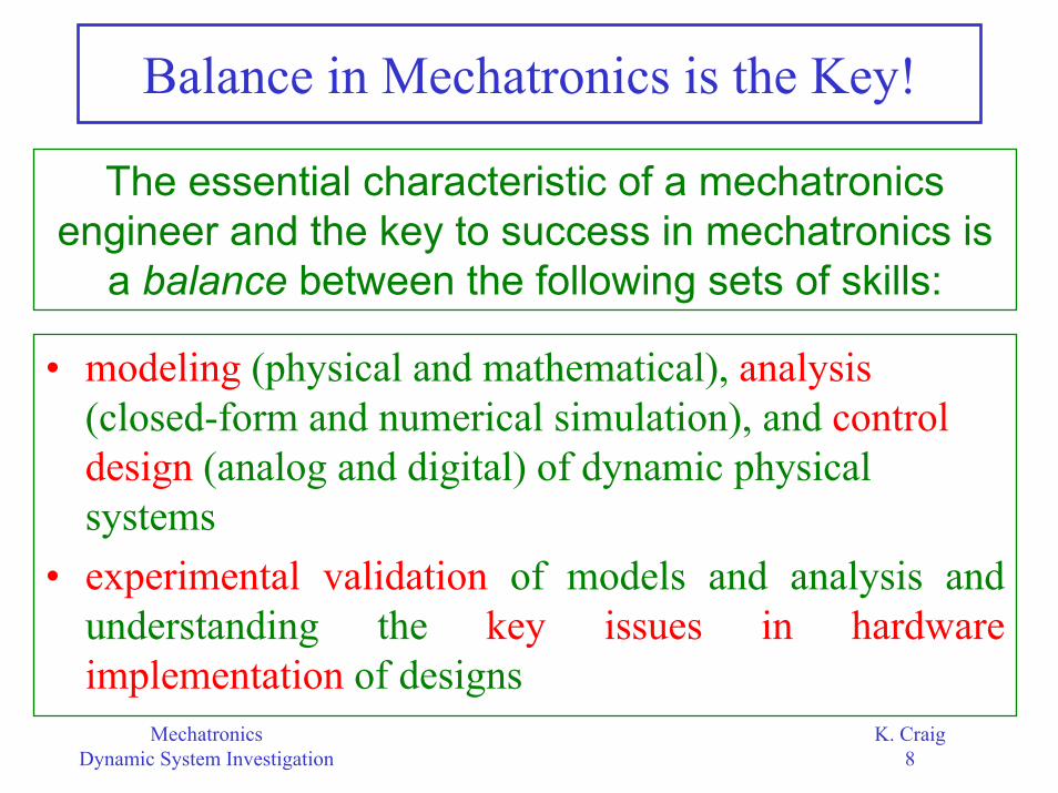
Balance in Mechatronics is the Key!
The essential characteristic of a mechatronics engineer and the key to success in mechatronics is
a balance between the following sets of skills:
• modeling (physical and mathematical), analysis(closed-form and numerical simulation), and control design (analog and digital) of dynamic physical systems
• experimental validation of models and analysis and understanding the key issues in hardware implementation of designs
MechatronicsDynamic System Investigation
K. Craig9
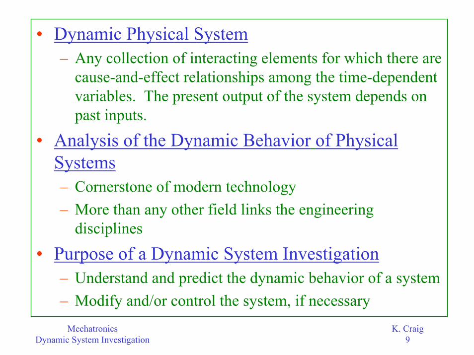
• Dynamic Physical System– Any collection of interacting elements for which there are
cause-and-effect relationships among the time-dependent variables. The present output of the system depends on past inputs.
• Analysis of the Dynamic Behavior of Physical Systems– Cornerstone of modern technology – More than any other field links the engineering
disciplines
• Purpose of a Dynamic System Investigation– Understand and predict the dynamic behavior of a system– Modify and/or control the system, if necessary
MechatronicsDynamic System Investigation
K. Craig10
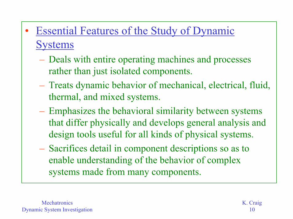
• Essential Features of the Study of Dynamic Systems– Deals with entire operating machines and processes
rather than just isolated components.– Treats dynamic behavior of mechanical, electrical, fluid,
thermal, and mixed systems.– Emphasizes the behavioral similarity between systems
that differ physically and develops general analysis and design tools useful for all kinds of physical systems.
– Sacrifices detail in component descriptions so as to enable understanding of the behavior of complex systems made from many components.

MechatronicsDynamic System Investigation
K. Craig11
– Uses methods which accommodate component descriptions in terms of experimental measurements, when accurate theory is lacking or is not cost-effective, and develops universal lab test methods for characterizing component behavior.
– Serves as a unifying foundation for many practical application areas, e.g., vibrations, measurement systems, control systems, acoustics, vehicle dynamics, etc.
– Offers a wide variety of computer software to implement its methods of analysis and design.

MechatronicsDynamic System Investigation
K. Craig12
• Stages of a Dynamic System Investigation– Physical System
• Define the physical system to be studied, along with the system boundaries, input variables, and output variables.
– Physical System to Physical Model• A physical model is an imaginary physical system
which resembles an actual system in its salient features, but which is simpler, more ideal, and is thereby more amenable to analytical studies. There is a hierarchy of physical models of varying complexity possible.
• Not oversimplified, not overly complicated - a slice of reality.

MechatronicsDynamic System Investigation
K. Craig13
• The astuteness with which approximations are made at the onset of an investigation is the very crux of engineering analysis.
• What is the purpose of the model? Develop a set of performance specifications for the model based on the specific purpose of the model. What features must be included? How accurately do they need to be represented?
• Truth Model vs. Design Model• Engineering Judgment is the Key!

MechatronicsDynamic System Investigation
K. Craig14
• Comments on Truth Model vs. Design Model– In modeling dynamic systems, we use engineering
judgment and simplifying assumptions to develop a physical model. The complexity of the physical model depends on the particular need, and the intelligent use of simple physical models requires that we have some understanding of what we are missing when we choose the simpler model over the more complex model.
– The truth model is the model that includes all the known relevant characteristics of the real system. This model is often too complicated for use in engineering design, but is most useful in verifying design changes or control designs prior to hardware implementation.

MechatronicsDynamic System Investigation
K. Craig15
– The design model captures the important features of the process for which a control system is to be designed or design iterations are to be performed, but omits the details which you believe are not significant.
– In practice, you may need a hierarchy of models of varying complexity:
• A very detailed truth model for final performance evaluation before hardware implementation
• Several less complex truth models for use in evaluating particular effects
• One or more design models

MechatronicsDynamic System Investigation
K. Craig16
Physical Modeling
Less Real, Less Complex, More Easily Solved
Truth Model Design Model
More Real, More Complex, Less Easily Solved
Hierarchy Of ModelsAlways Ask: Why Am I Modeling?

MechatronicsDynamic System Investigation
K. Craig17
– Physical Model to Mathematical Model• We derive a mathematical model to represent the
physical model, i.e., write down the differential equations of motion of the physical model.
• The goal is a generalized treatment of dynamic systems, including mechanical, electrical, electromechanical, fluid, thermal and mixed systems.
– Define System: Boundary, Inputs, Outputs– Define Variables: Through and Across Variables– Write System Relations: Dynamic Equilibrium Relations
and Compatibility Relations– Write Constitutive Relations: Physical Relations for Each
Element– Combine: Generate State Equations

MechatronicsDynamic System Investigation
K. Craig18
– Study Dynamic Behavior and Compare to Measured Dynamics
• Study the dynamic behavior of the mathematical model by solving the differential equations of motion either through mathematical analysis or computer simulation.
• Dynamic behavior is a consequence of the system structure - don’t blame the input!
• Seek a relationship between physical model structure and behavior.
• Develop insight into system behavior.

MechatronicsDynamic System Investigation
K. Craig19
• Compare the predicted dynamic behavior to the measured dynamic behavior from tests on the actual physical system; make physical model corrections, if necessary.
– Make Design Decisions• Make design decisions so that the system will
behave as desired:– modify the system (e.g., change the physical parameters of
the system)– control the system (e.g., augment the system, typically by
adding a dynamic system called a compensator or controller)

MechatronicsDynamic System Investigation
K. Craig20
Example of aDynamic System:Electro-PneumaticTransducer
This system can be collapsed into a simplified approximate overall model when numerical values are
properly chosen:
o
in
p Ke D 1
=τ +
dDifferential Operator Ddt
≡

MechatronicsDynamic System Investigation
K. Craig21
• It is interesting to note here that while the block diagram shows one input for the system, i.e., command voltage ein , there are possible undesired inputs that must also be considered.– For example, the ambient temperature will affect the
electric coil resistance, the permanent magnet strength, the leaf-spring stiffness, the damper-oil viscosity, the air density, and the dimensions of the mechanical parts. All these changes will affect the system output pressure po in some way, and the cumulative effects may not be negligible.

MechatronicsDynamic System Investigation
K. Craig22
Example of aDynamic System:Temperature Control System
Here, the electro-pneumatic transducer is a component in the
overall dynamic system.

MechatronicsDynamic System Investigation
K. Craig23
• Note that in the block diagram of this system, the detailed operation of the electropneumatic transducer is not made apparent; only its overall input/output relation is included.
• The designer of the temperature feedback-control dynamic system would consider the electropneumatic transducer an off-the-shelf component with certain desirable operating characteristics.
• The methods of system dynamics are used by both the electropneumatic transducer designer and the designer of the larger temperature feedback-control system.
MechatronicsDynamic System Investigation
K. Craig24
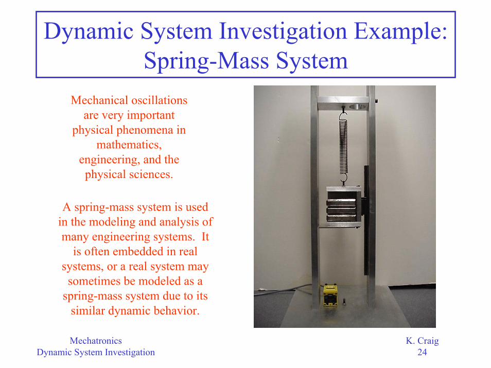
Dynamic System Investigation Example:Spring-Mass System
Mechanical oscillations are very important
physical phenomena in mathematics,
engineering, and the physical sciences.
A spring-mass system is used in the modeling and analysis of many engineering systems. It
is often embedded in real systems, or a real system may
sometimes be modeled as a spring-mass system due to its
similar dynamic behavior.

MechatronicsDynamic System Investigation
K. Craig25
• Physical System– A mass hanging at the tip of a tension spring that is
attached to a stationary rigid support constitutes the dynamic system for investigation.
– The motion of the spring-mass system is constrained by a linear bearing on the side of the support so that the mass oscillates only in one direction, the vertical direction.
– A non-contact optical (infrared) sensor is used to measure the position of the mass.
– The free oscillation of the spring-mass system is considered here; there is no externally-applied driving force acting on the system.

MechatronicsDynamic System Investigation
K. Craig26
• Physical-Model Simplifying Assumptions– The support to which the spring is attached is rigid.
This assumption in effect says that the environment is independent of system motions.
– The spring is pure, i.e., it only has the characteristic (elasticity) for which it is named. A pure spring has negligible mass and damping. This, of course, is an idealization as all springs have mass and dissipate energy upon cycling. If the spring mass is less than 10% of the mass attached to it, this is a reasonable assumption (except in high-speed applications). The energy dissipation in the spring is very small compared to other dissipation mechanisms in the system, so neglecting it is also reasonable.
MechatronicsDynamic System Investigation
K. Craig27
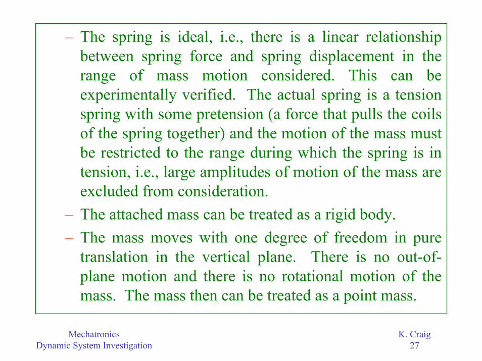
– The spring is ideal, i.e., there is a linear relationship between spring force and spring displacement in the range of mass motion considered. This can be experimentally verified. The actual spring is a tension spring with some pretension (a force that pulls the coils of the spring together) and the motion of the mass must be restricted to the range during which the spring is in tension, i.e., large amplitudes of motion of the mass are excluded from consideration.
– The attached mass can be treated as a rigid body. – The mass moves with one degree of freedom in pure
translation in the vertical plane. There is no out-of-plane motion and there is no rotational motion of the mass. The mass then can be treated as a point mass.

MechatronicsDynamic System Investigation
K. Craig28
– The friction in the system is parasitic, i.e., no energy dissipation mechanism has been designed into the system. Any air damping due to the motion of the mass in the air is negligible. The friction in the linear bearing is the main source of energy dissipation and, based on engineering experience, is a combination of viscous damping (proportional to the velocity of the mass and directed opposite to the mass motion) and dry-friction, or Coulomb damping, as it is called, (essentially constant in magnitude, independent of mass velocity, and directed opposite to the mass motion). Coulomb friction leads to a nonlinear mathematical model, while viscous friction leads to a linear mathematical model.
MechatronicsDynamic System Investigation
K. Craig29
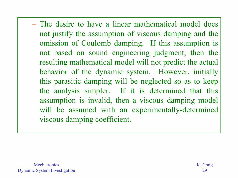
– The desire to have a linear mathematical model does not justify the assumption of viscous damping and the omission of Coulomb damping. If this assumption is not based on sound engineering judgment, then the resulting mathematical model will not predict the actual behavior of the dynamic system. However, initially this parasitic damping will be neglected so as to keep the analysis simpler. If it is determined that this assumption is invalid, then a viscous damping model will be assumed with an experimentally-determined viscous damping coefficient.

MechatronicsDynamic System Investigation
K. Craig30
– The system is vertical with the acceleration due to gravity pointing downward and constant in value.
– All parameters (mass m, spring constant k, viscous damping coefficient B) are constant, i.e., do not change with time or temperature, for example.

MechatronicsDynamic System Investigation
K. Craig31
• Physical ModelFixed
Support
FreeSpring
StaticEquilibrium
Motion
g
m
m
xs
kk
k
L
xd(t)+x(t)s
s
d
s d
m massm spring mass
L unstretched spring lengthk spring constantg acceleration due to gravity
x static spring stretchx dynamic spring stretchx total spring stretch = x x
======== +

MechatronicsDynamic System Investigation
K. Craig32
• Parameter Identification– Parameters in the physical model that need to
be identified are:• Mass m (kg) of the attached block - obtained by
weighing the block• Mass ms (kg) of the spring - obtained by weighing
the spring• Unstretched length of the spring L (m) - obtained by
direct measurement • Spring constant k (N/m) of the spring • Pretension force Ft (N) of the spring

MechatronicsDynamic System Investigation
K. Craig33
Tension Spring
Fspring (N)
Spring Pre-Tension
Ft (N)
k (N/m)
Spring Displacement(meters)
StaticEquilibrium
Displacement(m)
mg (N)
Two different masses must be used to obtain two data points (weight
and spring displacement) so that the assumed linear (straight-line) behavior of the spring can be plotted.
Experimental Determination of Spring Constant k and Pretension Force Ft

MechatronicsDynamic System Investigation
K. Craig34
– Parameter Identification Test Results• Unstretched spring length L = 0.127 m• Spring constant k = 491.1 N/m• Spring pretension force Ft = 9.521 N• Mass m = 5.231 kg• Spring mass ms = 0.08 kg• Static equilibrium displacement = 0.0851 m• Equation of force Fspring (N) vs. displacement x (m)
curve is: Fspring = 491.1x + 9.5206 and this linear curve is valid in the range 0 to 0.120 meters spring displacement.

MechatronicsDynamic System Investigation
K. Craig35
• Mathematical Model– Newton’s 2nd Law of Motion
– Free-Body Diagrams
2
x 2
d xF m mxdt
= =∑
+x
mg
m
k(xs+xd)+Ft
mg
m
kxs+Ft
+x
(a) (b)
Static Equilibrium Motion
MechatronicsDynamic System Investigation
K. Craig36
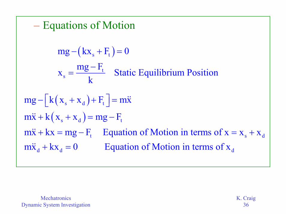
– Equations of Motion
( )s t
ts
mg kx F 0mg Fx Static Equilibrium Position
k
− + =
−=
( )( )
s d t
s d t
t s d
d d d
mg k x x F mx
mx k x x mg Fmx kx mg F Equation of Motion in terms of x x xmx kx 0 Equation of Motion in terms of x
− + + = + + = −
+ = − = ++ =

MechatronicsDynamic System Investigation
K. Craig37
0 5 10 15 20 2520
40
60
80
100
120
140
160
time (sec)
disp
lace
men
t x
(mm
)
P redicted Dynamic Response without Damping for Initial Displacement = 60 mm
Predicted Dynamic Response
nn n
k 9.69 rad/sec f 1.54 cycles/sec or Hzm 2
ωω = = = =
π
Initial Mass Displacement is 60 mm from
the Static Equilibrium
Position
staticequilibrium
position

MechatronicsDynamic System Investigation
K. Craig38
0 5 10 15 20 25 30 3520
40
60
80
100
120
140
160
time (sec)
disp
lace
men
t x
(mm
)
Actual Dynamic Response
Initial Mass Displacement is 60 mm from
the Static Equilibrium
Position
System damping has caused the oscillations to decay to zero in about 25 seconds.

MechatronicsDynamic System Investigation
K. Craig39
• Comparison: Actual vs. Predicted– The frequency of the oscillations for both responses is
approximately the same, i.e., 1.5 Hz. This is as expected from engineering experience since parasitic damping has little effect on the natural frequency of oscillations of the system.
– The oscillations of the mass in both the predicted response and the actual response is about the static equilibrium position, i.e., xs = 85.1 mm.
– The amplitude of the oscillations for both responses does not agree well at all. This also is as expected from engineering experience because even a small amount of damping will reduce the amplitude of oscillations significantly over time. The greater the damping, the faster the oscillations decay to zero.
MechatronicsDynamic System Investigation
K. Craig40
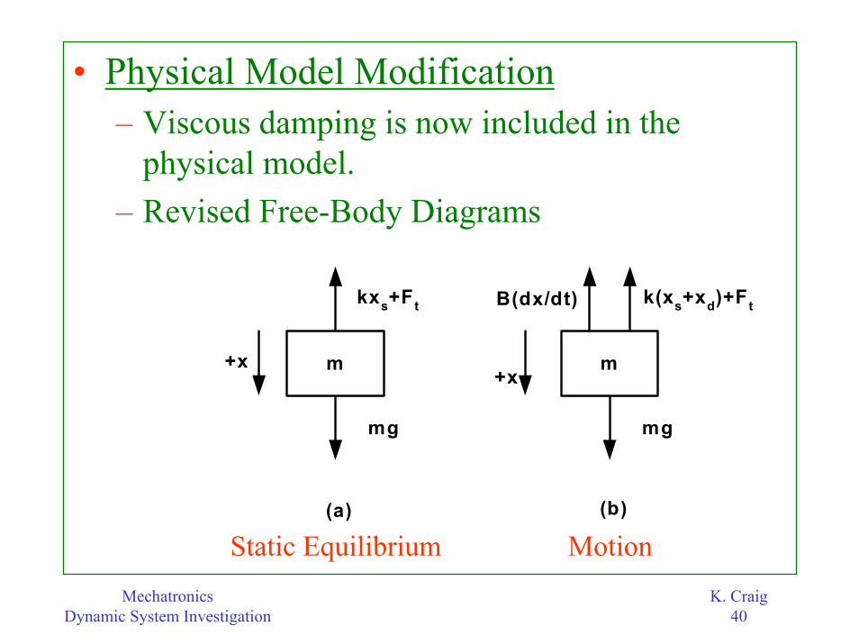
• Physical Model Modification– Viscous damping is now included in the
physical model.– Revised Free-Body Diagrams
+x
mg
m
k(xs+xd)+Ft
mg
m
kxs+Ft
+x
(a) (b)
B(dx/dt)
Static Equilibrium Motion

MechatronicsDynamic System Investigation
K. Craig41
( )( )
s d t
s d t
t s d
d d d d
mg Bx k x x F mx
mx Bx k x x mg Fmx Bx kx mg F Equation of Motion in terms of x x xmx Bx kx 0 Equation of Motion in terms of x
− − + + = + + + = −
+ + = − = ++ + =
– Revised Equations of Motion
MechatronicsDynamic System Investigation
K. Craig42
0 2 4 6 8 10 12 14 16 18 2020
40
60
80
100
120
140
160
Time (sec)
Dis
plac
emen
t x
(mm
)
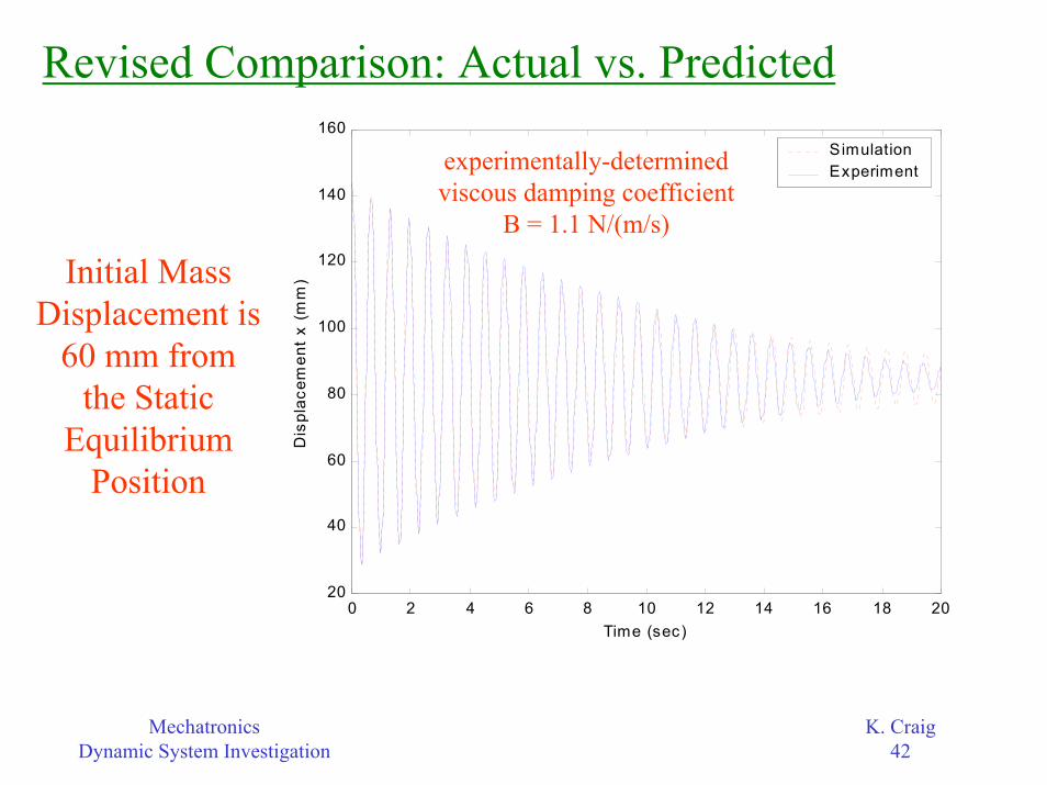
S imulationExperimentexperimentally-determined
viscous damping coefficientB = 1.1 N/(m/s)
Initial Mass Displacement is
60 mm from the Static
Equilibrium Position
Revised Comparison: Actual vs. Predicted
MechatronicsDynamic System Investigation
K. Craig43
– The agreement between the predicted response and the actual response is now quite good.
– The difference between the two responses becomes more noticeable as the oscillations diminish.
– This is expected because, again from engineering experience, Coulomb friction will begin to dominate the response over viscous friction when the system begins to slow down, and the physical model does not contain a Coulomb-friction term.

MechatronicsDynamic System Investigation
K. Craig44
• Conclusion– The dynamic system investigation process has
been demonstrated for the simple spring-mass system. Even for such a simple mechanical system, the process is still quite involved.
– Many simplifying assumptions must be made and sound engineering judgment used. The result of the investigation is a physical and mathematical model that together predict quite well the behavior of the actual physical system.

MechatronicsDynamic System Investigation
K. Craig45
– If a more detailed model is needed to more accurately predict the behavior of the actual system, the simplifying assumptions need to be reexamined and modified, if necessary, e.g., include Coulomb friction from the linear bearing, account for the mass of the spring.