Baku-Tbilisi-Ceyhan project. ESIA - Appendices (pdf 24.8 MB)
295
BTC PROJECT ESIA GEORGIA FINAL ESIA APPENDIX A I - REINS TATEMENT SUMMARY PLAN NOVEMBER 2002 APPENDIX A ANNEX I REINSTATEMENT SUMMARY PLAN TABLE OF CONTENTS Page No 1 INTRODUCTION 1 2 DOCUMENTATION 2 3 EROSION CLASSES 2 4 SITE CLEAN-UP 3 5 INTERIM REINSTATEMENT OF THE ROW 4 5.1 Land in Erosion Classes 1, 2 and 3 4 5.2 Land in Erosion Classes 4, 5, 6 and 7 (Except Boulder Fields) 4 5.3 Boulder fields 5 5.4 Watercourses 5 6 REINSTATEMENT OF LAND OTHER THAN ROW 5 6.1 Land at construction support facilities 5 6.2 Waste disposal sites 5 6.3 Roads and access tracks 5 7 REINSTATEMENT PROCEDURES 6 7.1 Topsoil removal and storage 6 7.2 Subsoil removal and storage 6 7.3 Trench excavation and pipeline padding 7 7.4 Reinstatement of soils 8 7.4.1 Reinstatement of subsoil 8 7.4.2 Reinstatement of topsoil 8 7.5 Temporary erosion control measures 9 7.5.1 General 9 7.5.2 Erosion matting 9 7.5.3 Sediment control 9 7.5.4 Soil-cuttings control 10 7.6 Permanent erosion control devices 10 7.6.1 Diverter berms 10 7.6.2 Berm outlets 10 7.6.3 Gabions 10 7.6.4 Trench breakers 10 7.7 Watercourses 11 8 BIO-RESTORATION 11 8.1 Objectives 11 8.2 Targets 11 8.3 Scheduling 12 8.4 Procedures for biorestoration 12 9 SPECIAL AREAS 12 10 RESTRICTING ACCESS 13 11 HANDOVER AND POST-CONSTRUCTION MAINTENANCE 13
Transcript of Baku-Tbilisi-Ceyhan project. ESIA - Appendices (pdf 24.8 MB)

BTC PROJECT ESIAGEORGIA
FINAL ESIA
APPENDIX A I - REINSTATEMENT SUMMARY PLANNOVEMBER 2002
APPENDIX A
ANNEX I REINSTATEMENT SUMMARY PLAN
TABLE OF CONTENTSPage No
1 INTRODUCTION 12 DOCUMENTATION 23 EROSION CLASSES 24 SITE CLEAN-UP 35 INTERIM REINSTATEMENT OF THE ROW 4
5.1 Land in Erosion Classes 1, 2 and 3 45.2 Land in Erosion Classes 4, 5, 6 and 7 (Except Boulder Fields) 45.3 Boulder fields 55.4 Watercourses 5
6 REINSTATEMENT OF LAND OTHER THAN ROW 56.1 Land at construction support facilities 56.2 Waste disposal sites 56.3 Roads and access tracks 5
7 REINSTATEMENT PROCEDURES 67.1 Topsoil removal and storage 67.2 Subsoil removal and storage 67.3 Trench excavation and pipeline padding 77.4 Reinstatement of soils 8
7.4.1 Reinstatement of subsoil 87.4.2 Reinstatement of topsoil 8
7.5 Temporary erosion control measures 97.5.1 General 97.5.2 Erosion matting 97.5.3 Sediment control 97.5.4 Soil-cuttings control 10
7.6 Permanent erosion control devices 107.6.1 Diverter berms 107.6.2 Berm outlets 107.6.3 Gabions 107.6.4 Trench breakers 10
7.7 Watercourses 118 BIO-RESTORATION 11
8.1 Objectives 118.2 Targets 118.3 Scheduling 128.4 Procedures for biorestoration 12
9 SPECIAL AREAS 1210 RESTRICTING ACCESS 1311 HANDOVER AND POST-CONSTRUCTION MAINTENANCE 13

BTC PROJECT ESIAGEORGIA
FINAL ESIA
APPENDIX A I - REINSTATEMENT SUMMARY PLANNOVEMBER 2002
TABLES
Table 3-1 Erosion classes 3

BTC PROJECT ESIAGEORGIA
FINAL ESIA
APPENDIX A I - REINS TATEMENT SUMMARY PLANNOVEMBER 2002
A-I-1
REINSTATEMENT SUMMARY PLAN
1 INTRODUCTIONReinstatement of project areas disturbed by pipeline construction activities (eg ROW, camps, pipe yards, etc) to the original landscape character is a specific objective aimed to achieve the goal of no harm to the environment, and encapsulates benefits that include:
Improved likelihood of maintaining pipeline integrity against inclement conditions and natural erosion
Natural landscape and it’s tourism resource value are maintained Soil fertility for both natural and agricultural environments is preserved, and thereby
reduces the risk of desertification is reduced Water catchments and the associated water quality are protected Bio-diversity of the global genetic pool is sustained
This plan summarises the specific requirements developed for reinstating areas disturbed by the project, and takes in to account the anticipated subsequent development of the SCP project.
The standards for reinstatement are current best practice, and have been developed from international standards and guidelines, and lessons learnt from projects in Europe, Africa, South America, and the Caucasus.
Issues addressed include topographical reinstatement, erosion control, and bio-restoration; and requirements for the extraction, re-use and if necessary the disposal of material excavated from the pipeline trench.
The reinstatement strategy is based on the following principles:
Areas disturbed by pipeline construction activities will be restored to pre-constructionconditions (eg contours) to the greatest extent possible
There will be no adverse impacts on sensitive habitats outside of the ROW as a result of construction activities, in particular when forming cuts on side slopes
Soils in disturbed areas will be stabilized, using both temporary and permanent controls, to protect the integrity of the pipeline and minimize potential sediment and erosion impacts
Topsoil will be handled and stored to retain soil structure, viability of its natural seed bank, and its fertility
Topsoil and subsoil operations will be carried out in a way which minimizes the risk of soil loss down slopes and into watercourses
Bio-restoration of disturbed areas will be to conditions similar to the immediately adjacent off-ROW, and will be undertaken in order to:(a) restore the ecology existing before construction, particularly the variety and
distribution pattern of plant species, using indigenous flora(b) establish sufficient vegetative cover to minimise erosion and meet the performance
target of Erosion Class 3 or better through restoration of the local plant community Surplus excavated material will be disposed of in an environmentally acceptable manner

BTC PROJECT ESIAGEORGIA
FINAL ESIA
APPENDIX A I - REINS TATEMENT SUMMARY PLANNOVEMBER 2002
A-I-2
Reinstatement activities will be monitored until environmental requirements and goals will be achieved
2 DOCUMENTATIONA Reinstatement Plan including Method Statements, inspection plans, and record portfolios for all erosion control and reinstatement works, will be produced by the Contractor for project approval. The documentation will comply with project, ESIA, pre-entry agreement, and any other relevant Authorities’ requirements.
The Contractor will make a photographic and or video record of the ROW before opening the ROW and following final reinstatement.
The construction ?ontractor will prepare method statements for project approval specifically addressing:
Environmentally Sensitive Areas Reinstatement of watercourse crossings, including generic methods for all watercourse
crossings and site-specific methods statements for significant or sensitive watercourse crossings in environmentally sensitive or special agricultural sections
Boulder fields Temporary and permanent measures to stabilise and control erosion for project affected
areas Special agricultural areas that support more complex agricultural systems eg canals, and
or irrigation systems
3 EROSION CLASSESErosion classes are used as the basis for determining erosion targets for temporary and permanent reinstatement. Table 3-1 below gives the definition of erosion classes. The aim is to meet erosion class 3 or better representing moderate erosion.
As a minimum the following standards will be achieved:
Very low risk of the depth of cover above the pipeline being reduced Very low risk of releasing soil off-site (where there is a risk of sediment significantly
impacting water bodies sediment interception devices will be installed) Low risk of damage to bio-restoration work through washing-out of seeds and plants
An erosion risk assessment has been undertaken of the route. This assessment identified areas of potential erosion and assigned erosion control measures for each area of the route.

BTC PROJECT ESIAGEORGIA
FINAL ESIA
APPENDIX A I - REINS TATEMENT SUMMARY PLANNOVEMBER 2002
A-I-3
Table 3-1 Erosion classes
Erosionclass
Verbalassessment
Erosionrate(t/ha)
Visual assessment
1 Very slight < 2 No evidence of compaction or crusting of the soil. No wash marks or scour features. No splash pedestals or exposed roots or channels
2 Slight 2-5 Some crusting of soil surface. Localised wash but no or minor scouring. Rills (channels <1m2 in cross-sectional area and < 30cm deep) every 50-100m. Small splash pedestals where stones or exposed roots protect underlying soil
3 Moderate 5-10 Wash marks. Discontinuous rills spaced every 20-50m. Splash pedestals and exposed roots mark level of former surface. Slight risk of pollution problems downstream
4 High 10-50 Connected and continuous network of rills every 5-10m or gullies (> 1m2 in cross-sectional area and > 30cm deep) spaced every 50-100m. Washing out of seeds and young plants. Reseeding may be required.Danger of pollution and sedimentation problems downstream
5 Severe 50-100 Continuous network of rills every 2-5m or gullies every 20m. Access to site becomes difficult. Revegetation work impaired and remedial measures required. Damage to roads by erosion and sedimentation. Siltation of water bodies
6 Very severe 100-500 Continuous network of channels with gullies every 5-10m. Surrounding soil heavily crusted. Integrity of the pipeline threatened by exposure. Severesiltation, pollution and eutrophication problems
7 Catastrophic > 500 Extensive network of rills and gullies; large gullies (> 10m2 in cross-sectional area) every 20m. Most of original surface washed away exposing pipeline.Severe damage from erosion and sedimentation on-site and downstream
4 SITE CLEAN-UPPrior to demobilization the contractor will clean-up all areas affected by construction operations after backfilling and before replacement of soil. In other project areas, the contractor will clean-up immediately on cessation of construction activity. Clean-up includes removal of all plant, equipment and materials not required for replacement of soil and subsequent bio-restoration.
In pre-developed areas (either for agriculture or industry) the cleaned-up condition will be equivalent to, or better than, the condition prior to construction.
Waste materials will not be left, or buried or disposed of in any way on any project area, except for:
BTC PROJECT ESIAGEORGIA
FINAL ESIA
APPENDIX A I - REINS TATEMENT SUMMARY PLANNOVEMBER 2002
A-I-4
on-site incineration excess soil and rock waste disposed of at approved waste disposal sites that will have been selected the
project and that have been approved by the relevant authorities to undertake suchoperations
5 INTERIM REINSTATEMENT OF THE ROWThe pipeline construction contractor will reinstate the full width of the BTC ROW as the base case.
Should the SCP installation follow directly from the BTC pipeline, full reinstatement will only be carried out on sections that will not be disturbed by SCP construction activities. Interim reinstatement will be carried out over the remaining portion of the ROW to cover the period between installation of the two pipelines. If there is a delay of more than 12 months between carrying out interim reinstatement and the start of SCP construction, the whole of any sectionwhich is subject to potentially severe or very severe erosion will be fully reinstated. Final reinstatement of the joint land would be the responsibility of the SCP project.
In environmentally sensitive areas the contractor will backfill and reinstate the ROW as far as practicable, immediately after installation of the pipeline.
Temporary reinstatement procedures will vary depending on the erodability of each particular area. Some of the specific tools used for interim reinstatement are described in Section 7.5.
The following briefly describes the activities for land in each of the erosion classes in Table 3-1.
5.1 LAND IN EROSION CLASSES 1, 2 AND 3The erosion risk on land in these classes is low and interim control measures will be limited to those necessary to maintain class 3. After installation of the BTC pipeline, the subsoil will be replaced in the trench. Topsoil will be stored according to requirements set out in section 7. Temporary erosion control measures will be installed and functional until the SCP is installed except in cases as described above.
5.2 LAND IN EROSION CLASSES 4, 5, 6 AND 7 (EXCEPTBOULDER FIELDS)
The subsoil will be returned to the areas from which it was excavated and compacted while topsoil will continue to be stored. The land will then be covered with erosion matting and any other temporary erosion control measures required will be installed.
By the time the SCP is installed, the mat should have deteriorated sufficiently so as to present no hazard to the following construction operations. Any residue of the mat after the second pipe is installed will be buried within the subsoil and below the topsoil and will decompose.

BTC PROJECT ESIAGEORGIA
FINAL ESIA
APPENDIX A I - REINS TATEMENT SUMMARY PLANNOVEMBER 2002
A-I-5
5.3 BOULDER FIELDSThe high density of stones within the boulder fields will generally be sufficient to protect the land against erosion, so no special measures are envisaged. Method Statements will be produced by the Contractor to meet erosion control targets.
5.4 WATERCOURSESInterim reinstatement does not apply to watercourse crossings - after installation of the first pipeline, stabilisation work will commence so that the 25 metres to either side of thewatercourse will be reinstated within 48 hours.
For each crossing the contractor will minimise the environmental impact by installingappropriate measures to prevent sediment entering the watercourse.
6 REINSTATEMENT OF LAND OTHER THAN ROW
6.1 LAND AT CONSTRUCTION SUPPORT FACILITIESTemporary construction facilities include worker camps, pipe dumps and hydrotest watertreatment areas. Reinstatement of the land will commence upon removal of individual facilities. Disturbed areas will be reinstated to a condition as good, if not better than that that existed prior to establishment of the facilities, and will be to the satisfaction of the owner/authority.
In environmentally sensitive areas, the original conditions and character will be restored as far as practicable.
6.2 WASTE DISPOSAL SITESThe contractor will close, cap, and landscape all waste disposal sites prior to demobilisation, unless otherwise agreed with the project. With the exception of waste soil/rock sites, this will be in accordance with the relevant requirements of the European Community relating to the management of waste disposal facilities. Bio-restoration will be undertaken as necessary toensure the site blends with the local environment. (See Section 10).
Sites that are used only for the disposal of excess soil and rock will be closed, capped and landscaped Each site will be vegetated as necessary to meet the erosion control requirements and to blend in with the local environment.
6.3 ROADS AND ACCESS TRACKSExisting roads will be reinstated to their original condition or better following completion of construction activities.

BTC PROJECT ESIAGEORGIA
FINAL ESIA
APPENDIX A I - REINS TATEMENT SUMMARY PLANNOVEMBER 2002
A-I-6
New and upgraded roads or tracks and other project areas in Environmentally Sensitive Areas will be removed and the land reinstated to its original condition, unless otherwise agreedfollowing consultation with all interested parties.
7 REINSTATEMENT PROCEDURESThe following subsections discuss activities that will take place prior to and duringreinstatement of the disturbed areas.
7.1 TOPSOIL REMOVAL AND STORAGETopsoil, containing the seed bank, is defined as the top layer of material on the land surface capable of supporting plant growth. Maintenance of topsoil quality, particularly its structure andthe integrity of its seed bank, are vital to both bio-restoration and erosion control.
Principles for removal and storage include:
The width to be stripped of topsoil will be the working width required to construct and install the BTC pipeline but exclu des the area that will be used to store topsoil. The contractor may apply for relaxation to this requirement where the ground is solid rock (ie no soil at all) taking into consideration the local conditions, pre-entry agreements and the need to satisfactorily reinstate the pipeline route. Any modification will be agreed with the project prior to works being carried out
Where excavation is necessary, the depth of the topsoil will be established and up to 300mm of topsoil will be stripped and stored in a dedicated place. Topsoil below 300mm will only be removed if this is specifically required
Topsoil will be stored in a manner that minimizes its loss and or degradation.Degradation of structure occurs when over-compacted by vehicles, while fertility and viability degradation occur when the topsoil is mixed with less fertile subsoil
Topsoil stacks will be placed to ensure that they: Are stable, and not subject to slumping or washout Drain freely and do not pond water Provide reasonable access across the ROW Maintain aerobic conditions
Stockpiles will be seeded where necessary to prevent weed growth Topsoil will not be used for bedding or padding material, or for trench breakers/plugs During handling, damage to topsoil structure will be avoided Topsoil handling under rainy conditions will be avoided for soils with a high clay
content or specifically wet conditions
7.2 SUBSOIL REMOVAL AND STORAGESubsoil will be managed so that it does not contribute directly or indirectly to excessive erosion. The following principles apply for removal and storage of sub-soil:
Subsoil will be excavated from the pipe trench and, in some cases, additionally from cutting of benches on sides of slopes
Subsoil will be stored separately from topsoil, and will not be mixed Subsoil will be returned to the excavated area, as far as practicable

BTC PROJECT ESIAGEORGIA
FINAL ESIA
APPENDIX A I - REINS TATEMENT SUMMARY PLANNOVEMBER 2002
A-I-7
Subsoil which cannot be re-used, ie returned to the trench or corridor ROW, will be placed in stockpiles
Stockpiles will be stable from collapse and drain freely Drainage will be provided to manage appropriately the water and sediment loads
running off the subsoil stockpiles (eg gaps, flumes, etc) Disposal of excess subsoil is discussed in the section 7.3
7.3 TRENCH EXCAVATION AND PIPELINE PADDINGThe creation of excess excavated material will be minimized as far as practicable. Excess material will be recovered and re-used to the greatest extent possible.
Fill materials will not be imported unless it is demonstrated that:
such fill is technically necessary and/or online processing is technically infeasible or uneconomic; and that suitable backfill cannot be provided by excavation techniques
Priorities for managing excess material are as follows:
1st priority: ROW Re-use:Where generated spoil is suitable for use as a construction material it will be re-used on the ROW for project infrastructure works materials; stability, erosion control, worker camps, AGIs, etc.
2nd priority: ROW / Project-Area Disposal: Use in project areas eg simulation of rock streams / glaciers in adjacent areas, hillside
contour blending Localised increase in finished surface height of ROW Increase in finished surface height of AGIs
All disposal/re-use in the project areas will be done without environmental impact to off-projectareas.
3rd priority Off ROW Re-use:Transfer to third Party for re-use purposes as raw or semi-finished materials, eg crushedandesite that may be suitable for road construction materials or for rail ballast.
4th priority: Off ROW Disposal:Potential disposal sites have been identified, and an operating permit will be required in case they are selected by the contractor. The contractor will plan, develop, operate and reinstate those sites to international standards. Alternatively, the contractor may propose other sites for approval. The contractor will be responsible for the technical and environmental assessment of such sites and for obtaining regulatory approval for alternative sites.
In principle, excess material will not be disposed of in the following area:
in environmentally sensitive areas (except with prior project approval) in areas adjacent to special agricultural sections in watercourses or valley bottoms

BTC PROJECT ESIAGEORGIA
FINAL ESIA
APPENDIX A I - REINS TATEMENT SUMMARY PLANNOVEMBER 2002
A-I-8
in windrows over the pipe on side slopes below benches or ridge cuttings where the side slope exceeds 45° where they will potentially interrupt concentrated overland flow in such a way as to cause unacceptable landscape (visual) impact on any open area where the slope exceeds 30°
Sites for the disposal of excess excavated material will, in general, comply with therequirements for ‘Inert’ waste disposal sites. However, provided a number of conditions are met, a reduced specification for the design of the site may apply. Conditions include the requirement that the site be stable and appropriately drained, with only natural materials deposited; and the transport vehicles do not transport other type of waste.
7.4 REINSTATEMENT OF SOILS
7.4.1 Reinstatement of subsoilTwo situations are considered: standard reinstatement and special reinstatement.
Standard reinstatementOn return of the subsoil to the trench or ROW, the subsoil will be compacted to levels similar to the adjacent undisturbed area. The depth of subsoil after settlement will not be above the level of the surrounding ground. After the subsoil has been returned and the land levelled, the subsoil will be ripped to a depth of 350-400mm, rendered to a loose and workable condition and contoured in keeping with the adjacent undisturbed ground.
Special Area reinstatementSpecial Area Reinstatement is applied where it has been necessary to cut a bench intothe hillside in order to lay the pipe and the intention is to restore the original contours by filling-in the bench, thereby removing any visual impact in the landscape. Locations where this is required relate to defined environmentally sensitive areas and special agricultural areas.
Upon completion of reinstatement of subsoil, disturbed areas will be inspected jointly by the contractor and the project for slope stability, relief, topographic diversity, acceptable surface water drainage capabilities, and compaction.
7.4.2 Reinstatement of topsoilTopsoil will not be mixed with spoil material during replacement. Only topsoil (and equivalent materials as permitted by this specification) will be re-spread over the surface. Topsoil will not be used for bedding material in the trench, and topsoil from unstripped/undisturbed areas will not be used to cover adjacent disturbances. Topsoil will not be handled under wet conditions or at times when the ground or topsoil are frozen.
All disturbed areas will be subject to final grading; however, measures will be taken prior to seeding to ensure disturbed areas remain in sufficiently rough condition to protect the stability of topsoil after its re-distribution and to promote vegetation growth.

BTC PROJECT ESIAGEORGIA
FINAL ESIA
APPENDIX A I - REINS TATEMENT SUMMARY PLANNOVEMBER 2002
A-I-9
7.5 TEMPORARY EROSION CONTROL MEASURES
7.5.1 GeneralTemporary erosion control measures to be installed to maintain stability, minimise erosion and washout, and protect watercourses include:
Flow breakers, or plugs of material (hard and soft), will be left in or installed at appropriate intervals, for trenches on longitudinal slopes to prevent scouring of the trench bottom
Water bars will be constructed on the ROW as necessary to control surface water runoff and erosion. Water bars will be designed to simulate the slope contour and direct and diffuse surface water away from the disturbed area
Flumes or other similar methods will be used to allow drainage and migration of water where cross drainage is necessary (ie where slopes require cutting
The ROW will be monitored for: Subsidence of the pipeline trench Slope wash Slumping and soil movements Loss of stored topsoil, subsoil or cuttings Status and success of re-vegetation Areas of disturbed ground off the ROW
If it is necessary to demobilise from any route section due to the onset of winter weather, temporary erosion control measures required to stabilise the ROW during the entiredemobilisation period will be installed where appropriate.
7.5.2 Erosion mattingErosion matting will be installed to provide an immediate protection to the slope againsterosion, prevent washing-out of seeds and enhance the micro-climatic conditions in the soil for plant germination and growth.
Once installed, erosion mats will be regularly inspected for degradation and installationintegrity. Mats will be maintained and replaced as required to achieve reinstatement objectives.
7.5.3 Sediment controlWhere the ROW intersects or is parallel to an environmental receptor (eg watercourse, wetland, water body or other sensitive area), sediment controls will be installed to prevent sediment and runoff significantly affecting the receptor. Sediment control will be used and maintained until ROW has been stabilized and meets project requirements.
Sediment interception devices include:
Silt Fences – installed in areas of low sheet flow

BTC PROJECT ESIAGEORGIA
FINAL ESIA
APPENDIX A I - REINS TATEMENT SUMMARY PLANNOVEMBER 2002
A-I-10
Straw Bale Barriers - installed in areas where small amounts of temporary sediment interception are required
Filter Berms - installed where there is a requirement to temporarily retain runoff water after a storm event, allowing sediment to settle
Sediment Traps - installed as required in the following locations: at outlets of ROW drainage systems; at the outlet of any structure which concentrates sediment-ladenrunoff and above a storm water drain which is in line to receive sediment-laden runoff
7.5.4 Soil-cuttings controlSide casting of soil cuttings is the traditional method of managing soil excavated from the ROW and trench. Wooden fences will be installed in areas of side slope and ridge construction to retain these cuttings within a reasonable project footprint during construction, and will aid reinstatement of the ROW. Fences will be designed for the anticipated loads to minimise risks to workers and the environment, and will be removed during final reinstatement of the ROW.
7.6 PERMANENT EROSION CONTROL DEVICESPermanent erosion control measures to be installed to maintain stability, minimise erosion and washout, and protect the environment are outlined in this section.
7.6.1 Diverter bermsDiverter berms are placed across the slope of the ROW to intercept runoff and convey it to a safe outlet. Berms are constructed according to a detailed specification.
7.6.2 Berm outletsWater outlets will provide disposal of runoff generated along the ROW. The runoff itself will be managed so as not to cause soil erosion or sediment transportation.
Water outlets will be installed at the end of each diverter berm. These outlets will effectively dissipate the energy of run off from the ROW before taking the water to a disposal point to minimise environmental impact.
7.6.3 GabionsGabions and gabion mattresses are used where there is a requirement to form large flexible but permeable structures such as; retaining walls, revetments, and weirs for earth retention. Gabion walls may be constructed and utilised for permanent recovery of the right of way and prevention or stabilisation of landslides that endanger stability of the land.
Gabions structures will be designed and constructed in accordance with the manufacturer’s specifications and project approved method statements.
7.6.4 Trench breakersTrench breakers are installed within the trench at locations along the pipeline route where the natural profiles, drainage patterns, and backfill materials cause the trench to act as a drain. They

BTC PROJECT ESIAGEORGIA
FINAL ESIA
APPENDIX A I - REINS TATEMENT SUMMARY PLANNOVEMBER 2002
A-I-11
may also be required at bases of slopes adjacent to water courses and wetlands and where drainage needs controlling.
7.7 WATERCOURSESInternational best practice will be used for constructing watercourse crossings. For significant crossings, in environmentally sensitive or special agricultural sections, special section designsand method statements will be developed and implemented to ensure site-specificenvironmental and social issues are considered appropriately.
The disturbed portion of the watercourse, the bed and banks, will be returned to pre-construction contours where possible, with backfill over the pipe at least as scour-resistant as the original bed material. Watercourse banks will be stabilised within 48hrs of backfilling.
Erosion and sediment control devices will be installed and maintained until re-vegetation is sufficiently established.
Where unstable channels exist downstream of a pipeline crossing, bed stabilisation work will be carried out appropriate to minimise the risk of bed erosion compromising the integrity of the pipeline.
Watercourse crossings will be inspected regularly until adequate stabilisation has been achieved. After which , routine inspections will be made approximately every three weeks until the end of the maintenance period.
8 BIO-RESTORATION
8.1 OBJECTIVESThe objectives are to
1) Restore ecological character the variety and distribution pattern of plant species, that existed prior to construction
2) Establish sufficient vegetation cover to reduce erosion to Erosion Class 3 or better through restoration of the local plant community
The long-term cover will be the native flora. The strategy for achieving its restoration is to use the natural seed bank contained within the topsoil, supplemented with seeds and transplants of local species as necessary.
8.2 TARGETSOriginal percentage cover will be estimated from the contractor’s photographic record of the route, or, in case of doubt, by reference to adjacent undisturbed areas. Against this recordappropriate targets and timeframes for achieving established growth will be set in agreement with the specialist bio-restoration contractors. Photographs should preferably be taken during spring or summer time.

BTC PROJECT ESIAGEORGIA
FINAL ESIA
APPENDIX A I - REINS TATEMENT SUMMARY PLANNOVEMBER 2002
A-I-12
‘Established’ means showing an initial healthy growth that would be expected for a particular species. This will minimise surface erosion and provide a sustainable, self-generating plant community under a range of conditions.
Soil, slope, perspective, and climatic conditions all affect rates of growth. Aftercare (watering, weeding, further application of fertiliser, etc) will be carried out during the maintenance period in order to meet the re-vegetation targets.
The bio-restoration progress for each section of the route, and other project areas, will be reported quarterly against the performance criteria agreed. Where the criteria are not met, or it appears that they will not be met within the reasonable timeframes, corrective action will be taken, that may include watering, weeding, over-seeding, fertiliser application, replacement of failed trees, etc.
8.3 SCHEDULINGBio-restoration work will be carried out during appropriate growing seasons. Sowing or planting will be scheduled for a period that is likely to be followed by sufficient rainfall to promote germination and establishment.
8.4 PROCEDURES FOR BIORESTORATIONPreliminary procedures for seeding and planting have been developed by the project as guidance to the construction contractor. The procedures developed account for the various habitat types such as meadows, as well as specific locations or species that are encountered along the route. However, these are optional and may be developed or substituted for other procedures by the construction contractor. Procedures developed include guidance on:
Seed storage Seed bed preparation Seeding/planting rates Seeding/planting methods eg trenches, pit planting, slot planting Soil additives eg fertilizer Watering requirements Use of erosion matting Optimum planting/seeding times
9 SPECIAL AREASSpecial Areas will be considered separately within the reinstatement plan being developed through method statements. Special areas include:
Boulder fields – These comprise two types:(a) very stony areas with boulders or cobbles strewn over the ground with no apparent
pattern with patches of soil between on which grass vegetation is found(b) areas of dense stone cover with no or very sparse vegetation and the boulders
arranged in streams aligned downslope (rock glaciers) or other types of patterned ground
BTC PROJECT ESIAGEORGIA
FINAL ESIA
APPENDIX A I - REINS TATEMENT SUMMARY PLANNOVEMBER 2002
A-I-13
Side Slopes & Cuttings - at environmentally sensitive locations or special agricultural areas, it is desired that the side slope be restored, as far as practicable to the original contours
Special agricultural areas – where canals, or irrigation channels, etc are to beencountered these are to be addressed through land use / system method statements
10 RESTRICTING ACCESSIn order to prevent rutting, subsequent erosion problems, damage to riparian areas, and induced access amplifying eg illegal logging, measures will be taken to prevent unauthorised use of the ROW as a roadway. Access will be blocked, at specific locations defined by the project .
11 HANDOVER AND POST-CONSTRUCTIONMAINTENANCE
Before the construction contractor relinquishes responsibility for the reinstated areas to the operating company, the project will:
carry out a final inspection of all project areas to agree with land owners that the pre-agreed standards of reinstatement have been met
should any shortfalls exist the project will carry out remedial work to the satisfaction of the landowners
During the contract maintenance period the project will be responsible for maintaining the standard of reinstatement and ensuring that the stated erosion class and bio-restoration targets are met.

BTC PROJECT ESIAGEORGIA
DRAFT FOR DISCLOSURE
APPENDIX B II - GETTING HSE RIGHTAPRIL 2002
APPENDIX B POLICY AND LEGAL FRAMEWORK
ANNEX II GETTING HSE RIGHT

Page 1 of 1
7/23/2014https://web.archive.org/web/20120823070704/http://www.bp.com/liveassets/bp_intern...


BTC PROJECT ESIAGEORGIA
FINAL ESIA
APPENDIX EI - LANDSCAPE ASSESSMENT & MANAGEMENT PLANNOVEMBER 2002
APPENDIX E ANNEX I LANDSCAPE ASSESSMENT AND MANAGEMENT PLAN
TABLE OF CONTENTSPage No
1.1 Landscape assessment study 11.2 Methodology 11.3 Description of conditions 3
1.3.1 Gardabani section 31.3.2 Tetritskaro section 41.3.3 Tsalka section 51.3.4 Borjomi/Bakuriani/Tabatskuri section 51.3.5 Akhaltsike section 6
1.4 Conclusions 71.4.1 Spatial structure 71.4.2 Landscape modification 71.4.3 Scenic/aesthetic quality 71.4.4 Landscape sensitivity 71.4.5 Visual intrusion 8
1.5 Landscape Plan 81.5.1 General recommendations at AGIs 81.5.2 Route corridor sections 9
Attachment 1: Figures
Attachment 2: Characteristics of Recommended Plants

BTC PROJECT ESIAGEORGIA
FINAL ESIA
APPENDIX EI - LANDSCAPE ASSESSMENT & MANAGEMENT PLANNOVEMBER 2002
EI-1
Appendix E Annex I
Landscape Assessment and Management PlanARE WE CALLING THIS A PLAN? OPORT?
1.1 LANDSCAPE ASSESSMENT STUDYA Landscape Assessment Study was undertaken by Paata Shanshiashvili, a Georgian Landscape Architect, during April – May 2001. The aim of the study was to conduct a field survey of landscapes during the spring months and of the main visual receptors within the Zone of Visual Influence (ZVI) of pipeline construction and permanent pipeline facilities, based on thePreferred Route Corridor from the Georgia -Azerbaijan to Georgia-Turkey border. The ZVIdefines the area from which construction activities and facilities can be viewed.
In order to identify the potential impacts on landscape of the construction and operation of the pipeline, the visual survey of landscapes was performed by applying methods of FieldReconnaissance and Expert Assessment (field viewing/ranking).
1.2 METHODOLOGYThe methodology is driven by the following ethical-esthetical criteria:
natural visual image should be safeguarded wherever possible traditional environment including its visual character contains a historic-cultural sense
of place and should be conserved during development as far as practicable esthetical harmony is a “built in” desire of human kind and that is why rules of
composition and sense of beauty should be fully incorporated into any development plan
For the purpose of the field survey, the proposed pipeline corridor was divided into 5 sections:
Akhaltsikhe Bakuriani/Tabatskuri Tsalka Tetritskaro Gardabani
LVU – is a landscape visual (spatial) unit that can be directly observed as a whole from any point within the unit.
LVS – is a landscape visual system. The LVS is determined by the physical geographical characters of the landscapes (e.g. natural boundaries such as mountain ranges and river valleys).
Along the proposed corridor 74 critical points were identified and more than 30 analytical spots points were selected within the LVS. For analytical purposes, more than 100 digital photographs along with video footage were taken from these points. Critical points are virtual points of thepipeline route that are selected to indicate what the pipeline will look like in the field. Most of

BTC PROJECT ESIAGEORGIA
FINAL ESIA
APPENDIX EI - LANDSCAPE ASSESSMENT & MANAGEMENT PLANNOVEMBER 2002
EI-2
the points are visually connected to existing landscape features such as a river or road. Critical points are identified and marked on support maps prior to the field survey.
Critical analytical spots are spots of the landscape within the Landscape Visual System (LVS) that depending on the physical geographical character of landscapes usually extends far beyond the pipeline corridor. The analytical points serve as locations for the visual survey and are studied during field reconnaissance for individual viewing and ranking, with the aim of assessing the ethic -aesthetic potential of landscapes within the LVS.
The landscapes in each section were studied by applying a visual systems model to characterise the spatial structure, visual component/element diversity and visual degree of existingmodification/domination. Characteristics of such a systems model include: character of spatial structure, visual diversity (structural diversity, quantity of components and elements), visual degree of modification of spatial structure, components and elements e.g. natural, modified,naturalized, artificial, etc.) and visual domination of space, components and elements.
According to the model, the spatial structure of landscapes is made up of LVU’s that form higher spatial aggregates or LVS. The main characteristics of the spatial structure are:
physical dimensions hierarchy (levels) and density of LVUs visual closure types of visual connections
The LVU is a spatial unit that reflects dual (discrete and continual) nature of space and is structured as a totality of observation points (i.e. not a single view from a specific point) demarcated from other groups of points.
The methodology is used for the following purposes:
To identify the ZVI for the proposed pipeline construction and permanent facilities; and To define the:
landscape character types;landscape sensitivity; andvisual intrusion within the ZVI.
The “landscape character types” within the ZVI are defined with respect to the visual/space structure, the visual diversity and the visual degree of modification. The classification takes into account relevant, inter-related factors such as topography/geomorphology, types of vegetation cover, hydro-graphic network, historic -cultural features and traditional landscape contexts,extent of anthropogenic elements and land-use patterns and scenic/aesthetic quality.
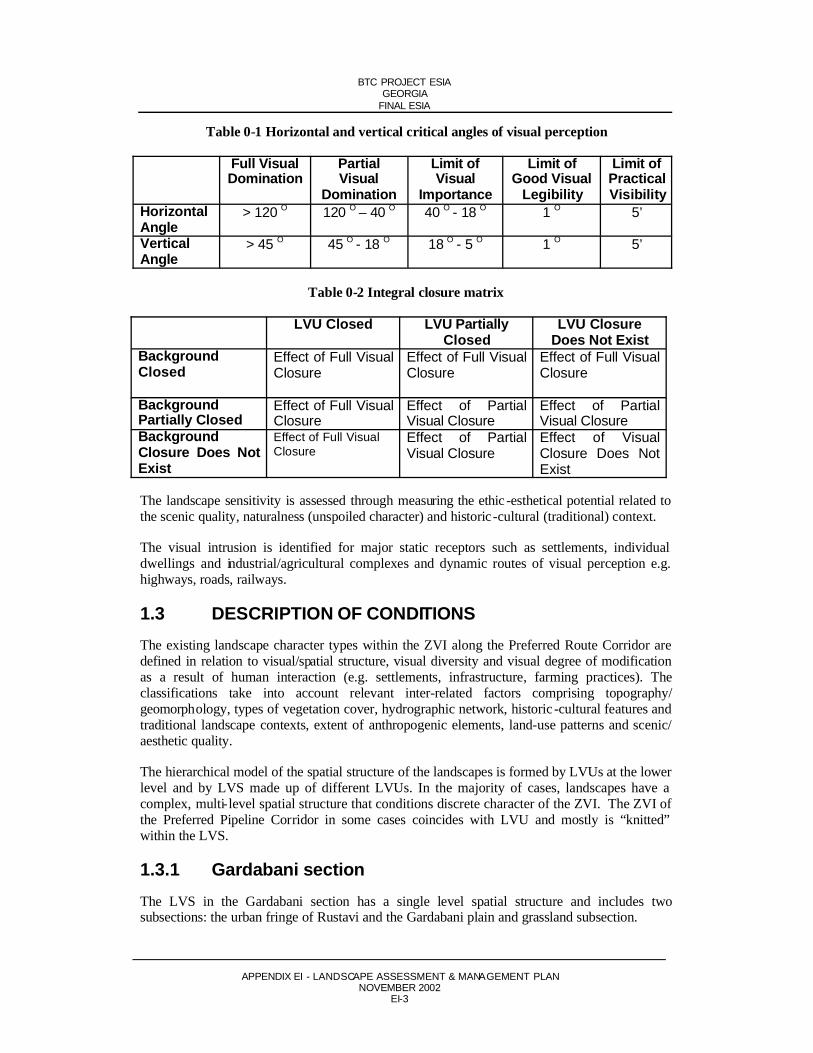
Critical angles of visual perception are optically defined. For example, if the object in horizontal section is so wide and close to the observer that it occupies a view of 120 degrees or more, and if in vertical section the object is so tall and close to the observer that occupies 45 degrees or more, then it can be stated that the observer will have a view full of visual domination. Table0-1 shows angles that are optically defined by the size of objects and the distance betweenobserver with respect to typical perception fillings.
The following tables show the criteria used to determine the visual intrusion and visibility of the LVUs.
BTC PROJECT ESIAGEORGIA
FINAL ESIA
APPENDIX EI - LANDSCAPE ASSESSMENT & MANAGEMENT PLANNOVEMBER 2002
EI-3
Table 0-1 Horizontal and vertical critical angles of visual perception
Full Visual Domination
PartialVisual
Domination
Limit of Visual
Importance
Limit of Good Visual
Legibility
Limit of PracticalVisibility
HorizontalAngle
> 120 O 120 O – 40 O 40 O - 18 O 1 O 5’
VerticalAngle
> 45 O 45 O - 18 O 18 O - 5 O 1 O 5’
Table 0-2 Integral closure matrix
LVU Closed LVU Partially Closed
LVU Closure Does Not Exist
BackgroundClosed
Effect of Full Visual Closure
Effect of Full Visual Closure
Effect of Full Visual Closure
BackgroundPartially Closed
Effect of Full Visual Closure
Effect of PartialVisual Closure
Effect of PartialVisual Closure
BackgroundClosure Does NotExist
Effect of Full Visual Closure
Effect of PartialVisual Closure
Effect of VisualClosure Does NotExist
The landscape sensitivity is assessed through measuring the ethic -esthetical potential related to the scenic quality, naturalness (unspoiled character) and historic-cultural (traditional) context.
The visual intrusion is identified for major static receptors such as settlements, individual dwellings and industrial/agricultural complexes and dynamic routes of visual perception e.g. highways, roads, railways.
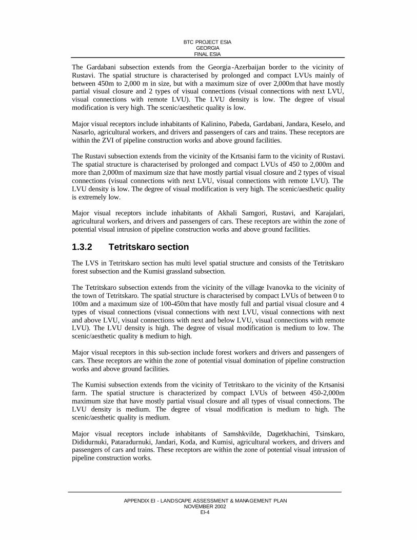
1.3 DESCRIPTION OF CONDITIONSThe existing landscape character types within the ZVI along the Preferred Route Corridor are defined in relation to visual/spatial structure, visual diversity and visual degree of modification as a result of human interaction (e.g. settlements, infrastructure, farming practices). Theclassifications take into account relevant inter-related factors comprising topography/geomorphology, types of vegetation cover, hydrographic network, historic -cultural features and traditional landscape contexts, extent of anthropogenic elements, land-use patterns and scenic/ aesthetic quality.
The hierarchical model of the spatial structure of the landscapes is formed by LVUs at the lower level and by LVS made up of different LVUs. In the majority of cases, landscapes have a complex, multi-level spatial structure that conditions discrete character of the ZVI. The ZVI of the Preferred Pipeline Corridor in some cases coincides with LVU and mostly is “knitted” within the LVS.
1.3.1 Gardabani sectionThe LVS in the Gardabani section has a single level spatial structure and includes twosubsections: the urban fringe of Rustavi and the Gardabani plain and grassland subsection.
BTC PROJECT ESIAGEORGIA
FINAL ESIA
APPENDIX EI - LANDSCAPE ASSESSMENT & MANAGEMENT PLANNOVEMBER 2002
EI-4
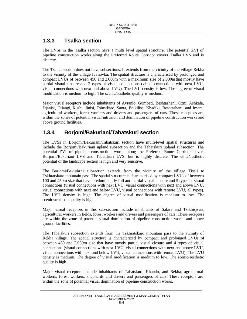
The Gardabani subsection extends from the Georgia -Azerbaijan border to the vicinity of Rustavi. The spatial structure is characterised by prolonged and compact LVUs mainly of between 450m to 2,000 m in size, but with a maximum size of over 2,000m that have mostly partial visual closure and 2 types of visual connections (visual connections with next LVU, visual connections with remote LVU). The LVU density is low. The degree of visualmodification is very high. The scenic/aesthetic quality is low.
Major visual receptors include inhabitants of Kalinino, Pabeda, Gardabani, Jandara, Keselo, and Nasarlo, agricultural workers, and drivers and passengers of cars and trains. These receptors are within the ZVI of pipeline construction works and above ground facilities.
The Rustavi subsection extends from the vicinity of the Krtsanisi farm to the vicinity of Rustavi. The spatial structure is characterised by prolonged and compact LVUs of 450 to 2,000m and more than 2,000m of maximum size that have mostly partial visual closure and 2 types of visual connections (visual connections with next LVU, visual connections with remote LVU). The LVU density is low. The degree of visual modification is very high. The scenic/aesthetic quality is extremely low.
Major visual receptors include inhabitants of Akhali Samgori, Rustavi, and Karajalari,agricultural workers, and drivers and passengers of cars. These receptors are within the zone of potential visual intrusion of pipeline construction works and above ground facilities.
1.3.2 Tetritskaro sectionThe LVS in Tetritskaro section has multi level spatial structure and consists of the Tetritskaro forest subsection and the Kumisi grassland subsection.
The Tetritskaro subsection extends from the vicinity of the village Ivanovka to the vicinity of the town of Tetritskaro. The spatial structure is characterised by compact LVUs of between 0 to 100m and a maximum size of 100-450m that have mostly full and partial visual closure and 4 types of visual connections (visual connections with next LVU, visual connections with next and above LVU, visual connections with next and below LVU, visual connections with remote LVU). The LVU density is high. The degree of visual modification is medium to low. The scenic/aesthetic quality is medium to high.
Major visual receptors in this sub-section include forest workers and drivers and passengers of cars. These receptors are within the zone of potential visual domination of pipeline construction works and above ground facilities.
The Kumisi subsection extends from the vicinity of Tetritskaro to the vicinity of the Krtsanisi farm. The spatial structure is characterized by compact LVUs of between 450-2,000mmaximum size that have mostly partial visual closure and all types of visual connections. The LVU density is medium. The degree of visual modification is medium to high. Thescenic/aesthetic quality is medium.
Major visual receptors include inhabitants of Samshkvilde, Dagetkhachini, Tsinskaro,Dididurnuki, Pataradurnuki, Jandari, Koda, and Kumisi, agricultural workers, and drivers and passengers of cars and trains. These receptors are within the zone of potential visual intrusion of pipeline construction works.
BTC PROJECT ESIAGEORGIA
FINAL ESIA
APPENDIX EI - LANDSCAPE ASSESSMENT & MANAGEMENT PLANNOVEMBER 2002
EI-5
1.3.3 Tsalka sectionThe LVSs in the Tsalka section have a multi level spatial structure. The potential ZVI of pipeline construction works along the Preferred Route Corridor covers Tsalka LVS and is discrete.
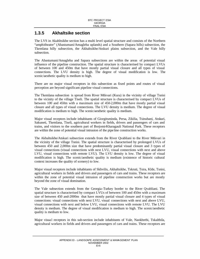
The Tsalka section does not have subsections. It extends from the vicinity of the village Rekha to the vicinity of the village Ivanovka. The spatial structure is characterised by prolonged and compact LVUs of between 450 and 2,000m with a maximum size of 2,000m that mostly have partial visual closure and 2 types of visual connections (visual connections with next LVU, visual connections with next and above LVU). The LVU density is low. The degree of visual modification is medium to high. The scenic/aesthetic quality is medium.
Major visual receptors include inhabitants of Avranlo, Gumbati, Beshtasheni, Ozni, Ashkala, Djanisi, Oliangi, Kushi, Jinisi, Tsinstkaro, Santa, Edikilisa, Khadiki, Beshtasheni, and Imera, agricultural workers, forest workers and drivers and passengers of cars. These receptors are within the zones of potential visual intrusion and domination of pipeline construction works and above ground facilities.
1.3.4 Borjomi/Bakuriani/Tabatskuri sectionThe LVSs in Borjomi/Bakuriani/Tabatskuri section have multi-level spatial structures andinclude the Borjomi/Bakuriani upland subsection and the Tabatskuri upland subsection. The potential ZVI of pipeline construction works along the Preferred Route Corridor coversBorjomi/Bakuriani LVS and Tabatskuri LVS, but is highly discrete. The ethic/aestheticpotential of the landscape section is high and very sensitive.
The Borjomi/Bakuriani subsection extends from the vicinity of the village Tiseli toTskhratskaro mountain pass. The spatial structure is characterised by compact LVUs of between 100 and 450m size that have predominantly full and partial visual closure and 5 types of visual connections (visual connections with next LVU, visual connections with next and above LVU, visual connections with next and below LVU, visual connections with remote LVU, all types). The LVU density is high. The degree of visual modification is medium to low. Thescenic/aesthetic quality is high.
Major visual receptors in this sub-section include inhabitants of Sakire and Tsikhisjvari,agricultural workers in fields, forest workers and drivers and passengers of cars. These receptors are within the zone of potential visual domination of pipeline construction works and above ground facilities.
The Tabatskuri subsection extends from the Tskhratskaro mountain pass to the vicinity of Rekha village. The spatial structure is characterized by compact and prolonged LVUs ofbetween 450 and 2,000m size that have mostly partial visual closure and 4 types of visual connections (visual connections with next LVU, visual connections with next and above LVU, visual connections with next and below LVU, visual connections with remote LVU). The LVU density is medium. The degree of visual modification is medium to low. The scenic/aesthetic quality is high.
Major visual receptors include inhabitants of Tabatskuri, Khando, and Rekha, agricultural workers, forest workers, shepherds and drivers and passengers of cars. These receptors are within the zone of potential visual domination of pipeline construction works.
BTC PROJECT ESIAGEORGIA
FINAL ESIA
APPENDIX EI - LANDSCAPE ASSESSMENT & MANAGEMENT PLANNOVEMBER 2002
EI-6
1.3.5 Akhaltsike sectionThe LVS in Akahltsikhe section has a multi level spatial structure and consists of the Northern “amphitheatre” (Abastumani/Amagleba uplands) and a Southern (Sapara hills) subsection, the Tkemlana hilly subsection, the Akhaltsikhe/Atskuri plains subsection, and the Vale hillysubsection.
The Abastumani/Amagleba and Sapara subsections are within the areas of potential visual influence of the pipeline construction. The spatial structure is characterised by compact LVUs of between 100 and 450m that have mostly partial visual closure and all types of visual connections. The LVU density is high. The degree of visual modification is low. Thescenic/aesthetic quality is medium to high.
There are no major visual receptors in this subsection as fixed points and routes of visual perception are beyond significant pipeline visual connections.
The Tkemlana subsection is spread from River Mtkvari (Kura) in the vicinity of village Tsnisi to the vicinity of the village Tiseli. The spatial structure is characterised by compact LVUs of between 100 and 450m with a maximum size of 450-2,000m that have mostly partial visual closure and all types of visual connections. The LVU density is medium. The degree of visual modification is medium to high. The scenic/aesthetic quality is medium.
Major visual receptors include inhabitants of Giorgitsminda, Persa, Zikilia, Tsinubani, Atskuri,Sakuneti, Tkemlana, Tiseli, agricultural workers in fields, drivers and passengers of cars and trains, and visitors to the southern part of Borjomi-Kharagauli National Park. These receptors are within the zone of potential visual intrusion of the pipe line construction works.
The Akhaltsikhe/Atskuri subsection extends from the River Qvabliani to the River Mtkvari in the vicinity of the village Tsnisi. The spatial structure is characterised by prolonged LVUs of between 450 and 2,000m size that have predominantly partial visual closure and 3 types of visual connections (visual connections with next LVU, visual connections with next and above LVU, visual connections with remote LVU). The LVU density is low. The degree of visual modification is high. The scenic/aesthetic quality is medium (existence of historic cultural context increases the quality of scenery) to low.
Major visual receptors include inhabitants of Skhvilis, Akhaltsikhe, Tskruti, Tsira, Klde, Tsnisi, agricultural workers in fields and drivers and passengers of cars and trains. These receptors are within the zone of potential visual intrusion of pipeline construction works but are mostly beyond the zone of visual domination.
The Vale subsection extends from the Georgia -Turkey border to the River Qvabliani. The spatial structure is characterised by compact LVUs of between 100 and 450m with a maximum size of between 450 and-2000m that have mostly partial visual closure and 4 types of visual connections: visual connections with next LVU, visual connections with next and above LVU, visual connections with next and below LVU, visual connections with remote LVU. The LVU density is medium. The degree of visual modification is medium to high. The scenic/aesthetic quality is medium to low.
Major visua l receptors in this sub-section include inhabitants of Vale, Naokhrebi, Tskaltbila, agricultural workers in fields and drivers and passengers of cars and trains. These receptors are

BTC PROJECT ESIAGEORGIA
FINAL ESIA
APPENDIX EI - LANDSCAPE ASSESSMENT & MANAGEMENT PLANNOVEMBER 2002
EI-7
within the zone of potential visual intrusion of above ground facilities and pipeline construction activities, but are beyond the zone of visual domination.
1.4 CONCLUSIONSVisual intrusion on the landscape as a result of construction activities and the existence of Above Ground Facilities is the dominant landscape impact. The significance of the visual intrusion varies depending on the ethic -esthetic potential of the landscape. The criteria used to determine ethic -esthetic potential and the corresponding potential within pipeline route sections are summarised below.
1.4.1 Spatial structureThe spatial structure of the landscapes along the pipeline route varies significantly. The Borjomi Bakuriani section is the most complex and the Tsalka section is the simplest. The density of LVUs in Borjomi/Bakuriani is 10 whilst in Tsalka it is 1.9. LVUs of large size (from 450 to 2,000m) are only 15% of the total in Borjomi/Bakuriani whilst in Tsalka they are 56% of the total. Six types of visual connections among LVUs occur in the Borjomi/Bakuriani, Akhaltsikhe and Tetritskaro areas whilst only 2 types occur in Tsalka.
1.4.2 Landscape modificationThe degree of modification of the landscapes as a result of human activity to date also differs significantly along the route. The Gardabani section is modified to the greatest extent where the landscape is dominated by the Rustavi Power Station and associated infrastructure. TheAkhaltsikhe and Tetritskaro sections are less modified and comprise a mix of landscapesmodified in varying degrees by human activities. The Borjomi/Bakuriani and Tsalka sections are modified to the least extent and comprise of largely natural landscapes.
1.4.3 Scenic/aesthetic qualityThe scenic/aesthetic quality of the landscapes also varies along the route. TheBorjomi/Bakuriani Tabatskuri section has the highest scenic value. In the Tetritskaro and Tsalka area the scenic/aesthetic quality is moderate but the area has high potential. The Akhaltsikhe section has moderate scenic/aesthetic quality and moderate potential. The Gardabani section has low scenic value and low potential.
1.4.4 Landscape sensitivityThe most sensitive landscapes are concentrated in the mountainous and forested sections of the corridor. Particularly sensitive landscapes are located in Akhaltsikhe (from the River Quabliani to the Turkish/Georgia border), in Borjomi/Bakuriani/Nariani (from Tiseli village to Rekha village), and in the Tetritskaro forested hills.
The sensitive landscapes have high scenic quality, almost unspoilt visual character and animportant historic -cultural context. Therefore, in these areas, the impact of the proposedconstruction works will be more dramatic.

BTC PROJECT ESIAGEORGIA
FINAL ESIA
APPENDIX EI - LANDSCAPE ASSESSMENT & MANAGEMENT PLANNOVEMBER 2002
EI-8
1.4.5 Visual intrusionThe visually affected LVS of the corridor from east to west is extended throughout Lower Kartli, Trialeti, Tori and Meskheti. The hierarchical model of spatial structure of the landscapes formed by LVUs within the LVS, in the majority of cases have multi level complex character, that conditions the discrete character of the ZVI (ZVI of the Pipeline Corridor in some cases coincides with the LVU and mostly is “knitted” within the LVS).
The extent of the visual intrusion arising as a result of pipeline construction activities varies depending on the nature and relief of the surrounding environment along with the population density in the area. As a result, permanent or temporary visual intrusion is spread throughout the LVS. In particular, major visual receptors are located on the bottom (first) level of the LVS in Akhaltsikhe, Tsalka, Tetritskaro and Gardabani, and on all levels in Borjomi/Bakuriani
1.5 LANDSCAPE PLANEnvironmental assessment and the design of landscaping mitigation measures has taken place in tandem. Feedback and input between the environmental assessment team, the landscapearchitect and pipeline engineers throughout the project design phase permits sensitive design early in the project and in particular during pipeline routing. This section details general and site specific landscaping recommendations along the ROW and at AGIs.
Visual intrusion along the ROW during construction will be mitigated for through the adoption of a number of measures. Maximum effort will be applied to restore the visual character of the landscape following construction. Grading and benching of the ROW, and subsequent re-grading and restoration of original contours will minimise landscape impact. A fullreinstatement plan (see Appendix A) will be implemented and will be monitored as part of the pipeline surveillance. Continued erosion control will be implemented through the use of diverter berms, silt fences and trench breakers.
The linear character of the pipeline route will be disguised through the avoidance of side-slopes.Sight-lines will be avoided through the use of dog-legs in the ROW and through theincorporation of scalloped edges to tree-cut-lines.
1.5.1 General recommendations at AGIsAt AGIs, a number of landscape mitigation measures have been put forward by the landscape architect and include:
No soil, grass, shrubs or trees will be cleared beyond a carefully defined boundarycommensurate with construction requirements;
Within the perimeter of the AGI, consideration will be given to interspersingadministration and/or accommodation buildings with open grass cover and, wherepracticable and where not a safety hazard, shrubs and trees;
Facility walls will be finished (texture, colour, etc.) and screened with trees and shrubs as appropriate to blend with the surrounding natural landscape.
Non-natural, visually active and metallic colours and textures will be avoided. Colors sympathetic to the natural landscape will be used, including brown, grey and greencolors and very limited black, yellow and red.
BTC PROJECT ESIAGEORGIA
FINAL ESIA
APPENDIX EI - LANDSCAPE ASSESSMENT & MANAGEMENT PLANNOVEMBER 2002
EI-9
The height and mass of buildings will be minimised, for example by using pitched roofs where possible; Site lighting (where applicable) will be designed and located to reduce off-site glare to a minimum, and minimise the impact on visual amenity at night, having regard to security and safety requirements. Lighting will be soft.
Site specific planting schemes for a number of AGIs are specified below.
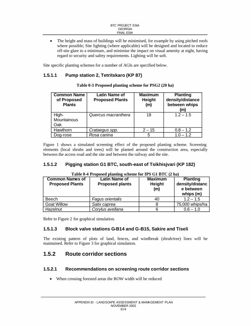
1.5.1.1 Pump station 2, Tetritskaro (KP 87)
Table 0-3 Proposed planting scheme for PSG2 (20 ha)
Common Name of Proposed
Plants
Latin Name of Proposed Plants
MaximumHeight
(m)
Plantingdensity/distancebetween whips
(m)High-MountainousOak
Quercus macranthera 18 1.2 – 1.5
Hawthorn Crataegus spp. 2 – 15 0.8 – 1.2Dog-rose Rosa canina 5 1.0 – 1.2
Figure 1 shows a simulated screening effect of the proposed planting scheme. Screening elements (local shrubs and trees) will be planted around the construction area, especiallybetween the access road and the site and between the railway and the site.
1.5.1.2 Pigging station G1 BTC, south-east of Tsikhisjvari (KP 182)
Table 0-4 Proposed planting scheme for IPS G1 BTC (2 ha)Common Names of Proposed Plants
Latin Name of Proposed plants
MaximumHeight
(m)
Plantingdensity/distanc
e between whips (m)
Beech Fagus orientalis 40 1.2 – 1.5Goat Willow Salix caprea 8 75,000 whips/haHazelnut Corylus avellana 6 0.6 – 1.0
Refer to Figure 2 for graphical simulation.
1.5.1.3 Block valve stations G-B14 and G-B15, Sakire and Tiseli
The existing pattern of plots of land, fences, and windbreak (shrub/tree) lines will bemaintained. Refer to Figure 3 for graphical simulation.
1.5.2 Route corridor sections
1.5.2.1 Recommendations on screening route corridor sections
When crossing forested areas the ROW width will be reduced

BTC PROJECT ESIAGEORGIA
FINAL ESIA
APPENDIX EI - LANDSCAPE ASSESSMENT & MANAGEMENT PLANNOVEMBER 2002
EI-10
When crossing forested areas the linear character of the ROW will be “hidden” through irregular planting of trees and shrubs in the middle zone of the corridor and maintaining meadows within forests adjacent to the corridor
In the Sakire section, the pipeline corridor will be built to maximize reinstatement potential. This could result in two terraces screened behind tree lines that will not contrast with the existing character of landscape pattern, or could result in one reduced ROW.
The steep slope section at Tskhratskaro will be restored fully including soil, herbaceous cover and shrubs
The floodplain forest within the 100m corridor of the Mtkvari River crossing will be replanted in accordance with the project replanting scheme.
1.5.2.2 River Mtkvari Crossing 2, KP 221 – KP 222
Table 0-5 Proposed planting scheme for Mtkvari Crossing 2 (4.5 ha)
Common Names of Proposed Plants
Latin Name of Proposed Plants
MaximumHeight
m
Plantingdensity/distancebetween whips
(m)Black Poplar Populus nigra 30 - 40 1.0 – 1.2Willow Salix spp. 15 1.1 – 1.3Tamarisk Tamarix
ramosissima5 0.7 – 0.9
Sea Buckthorn Hipopphaërhamnoides
7 1,100 whips/ha
Refer to Figure 4 for graphical simulation.
1.5.2.3 Route section KP 182 – KP 183, south-east of Village Tsikhisjvari
The proposed planting scheme covers 7.2 ha.
Table 0-6 Proposed planting scheme for Eastern Part, KP 182 – KP 183
Common Names of Proposed Plants
Latin Name of Proposed Plant
Maximum Heightm
Plantingdensity/distance
between whips (m)Pine Pinus sylvestris 35 10,000 whips/haGoat Willow Salix caprea 8 75,000 whips/haHazelnut Corylus avellana 6 0.6 – 1.0
Table 0-7 Proposed planting scheme for Western Part, KP 182 – KP 183
Common Names of Proposed Plants
Latin Name of Proposed Plants
Maximum Heightm
Plantingdensity/distance
between whips (m)Beech Fagus orientalis 40 1.2 - 1.5Goat Willow Salix caprea 8 75,000 whips/haHazelnut Corylus avellana 6 0.6 – 1.0

BTC PROJECT ESIAGEORGIA
FINAL ESIA
APPENDIX EI - LANDSCAPE ASSESSMENT & MANAGEMENT PLANNOVEMBER 2002
EI-11
Refer to Figure 5 for graphical simulation of the proposed scheme.
Attachment 1: Figures


BTC PROJECT ESIAGEORGIA
FINAL ESIA
APPENDIX EI - LANDSCAPE ASSESSMENT & MANAGEMENT PLANNOVEMBER 2002
EI-17
Attachment 2: Characteristics of RecommendedPlants
Plant Common Name Latin Name Standard size of
whips (m)Maximumheight (m)
Plantingdensity/distancebetween whips
(m)Tetritskaro PS-02High-MountainousOak
Quercusmacranthera 0.1 18 1.2-1.5
Hawthorn Crataegus spp.Propagated byberries 2-7-15
Dog-rose Rosa canina 0.1-0.12 5 1.0-1.2Tsikhisjvari Forest (east)
Pine Pinus sylvestris 0.15-0.3 3510,000 per
hectare
Goat Willow Salix capreashoots fully covered with soil 8
75,000 per hectare
Hazelnut Corylus avellana 0.3 6 0.6-1.0Pigging Station
Beech Fagus orientalis 0.1 40 1.2-1.5
Goat Willow Salix capreashoots fully covered with soil 8
75,000 per hectare
Hazelnut Corylus avellana 0.3 6 0.6-1.0Tsikhisjvari Forest (west)
Beech Fagus orientalis 0.1 40 1.2-1.5
Goat Willow Salix capreashoots fully covered with soil 8
75,000 per hectare
Hazelnut Corylus avellana 0.3 6 0.6-1.0Sakire Forest
Spruce Picea orientalis 0.1-0.2 50 1.2-1.5
FirAbiesnordmanniana 0.1 80 1.2-1.5
Hazelnut Corylus avellana 0.3 6 0.6-1.0Dog-rose Rosa canina 0.1-0.12
Mtkvari xingBlack Poplar Populus nigra 0.1-0.15 30-40 1.0-1.2
Willow Salix spp.shoots fully covered with soil 15
TamariskTamarixramosissima
shoots fully covered with soil 5 0.7-0.9
Sea buckthornHipopphaërhamnoides 0.1 7 1,100 per hectare

Page 1 of 1
7/23/2014https://web.archive.org/web/20120823071120/http://www.bp.com/liveassets/bp_intern...

BTC PROJECT ESIAGEORGIA
FINAL ESIA
APPENDIX E II - AIR QUALITY MODELLING STUDYNOVEMBER 2002
APPENDIX E ENVIRONM ENTAL IMPACTS AND MITIGATION
ANNEX II AIR QUALITY MODELLING STUDY
TABLE OF CONTENTSPage No
1 INTRODUCTION 12 ATMOSPHERIC RELEASES 23 ASSESSMENT CRITERIA 3
3.1 Emissions limits for thermal combustion plants 33.2 Environmental air quality standards 3
4 AMBIENT AIR QUALITY 55 INDICATIVE STACK HEIGHTS 66 INTRODUCTION TO AIR DISPERSION MODELLING 7
6.1 Dispersion model input data 76.1.1Exhaust gas release characteristics 76.1.2Meteorological conditions 86.1.3Structures within the vicinity 96.1.4Local topography 96.1.5Grid size 96.1.6Assumptions 10
7 TURBINE DRIVER STACK HEIGHT 118 DISPERSION MODELLING RESULTS 12
8.1 Short term concentrations 128.2 Long term concentrations 12
9 CONCLUSION 13
TABLES
Table 2-1 Principal releases resulting from turbine driver operation 2Table 3-1 Assessment criteria for the thermal combustion plant 3Table 3-2 EU ambient air quality assessment criteria 4Table 5-1 Input parameters for D1 stack height determination 6Table 6-1 Dispersion model input parameters 8Table 8-1 Short-term dispersion modelling results 12Table 8-2 Long-term dispersion modelling results 12
FIGURES
Figure 1 9
ATTACHMENTS
ATTACHMENT 1 – ISOPLETHS 14

BTC PROJECT ESIAGEORGIA
FINAL ESIA
APPENDIX E II - AIR QUALITY MODELLING STUDYNOVEMBER 2002
E- II-1
Appendix E Annex II
Air Quality Modelling Study For BTC Crude OilPipeline Above Ground Installation
1 INTRODUCTIONThe following report presents a dispersion modelling study of the atmospheric emissions resulting from the operation of proposed oil pumping stations in Georgia, associated with the BTC Oil Pipeline Project. The pipeline is expected to begin exporting crude oil from Sangachal (Azerbaijan) in 2004.
Despite all cost effective means of mitigation, significant atmospheric releases are anticipated tobe associated with turbine drivers needed to mechanically drive oil pumping plant within Georgia. Two pump stations are proposed in the Georgian section of the pipeline (noted as PS G1 at KP 3.6 and PS G2 at KP 87).
During peak export, it is expected that four mainline oil export pumps will be required (with a fifth pump on standby). To provide suitable mechanical power to the pumps, each will be driven by a duel fuel turbine, which will provide 8MW power. At approximately 27% efficiency, each turbine driver will require the equivalent of 32MW of fuel to operate at maximum load. Each site, therefore, has an aggregated net rated thermal input of 128MW.
To maintain a conservative approach to this assessment, it has been assumed, based upon a reasonable worst case scenario, that turbine drivers will operate on a distillate fuel. However, it is anticipated that should the proposed SCP gas pipeline be constructed within Georgia(expected to begin export in 2006), all turbine drivers will operate on natural gas.
Preliminary dispersion modelling of the operational releases from the proposed thermal power plant has been conducted to determine appropriate stack design for turbine drivers at each site, and assess where additional mitigation may be required to achieve the project specificenvironmental standards.
BTC PROJECT ESIAGEORGIA
FINAL ESIA
APPENDIX E II - AIR QUALITY MODELLING STUDYNOVEMBER 2002
E- II-2
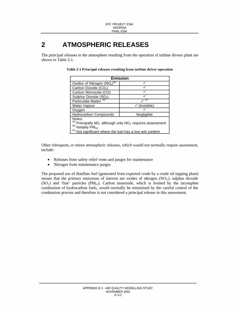
2 ATMOSPHERIC RELEASESThe principal releases to the atmosphere resulting from the operation of turbine drivers plant are shown in Table 2-1.
Table 2-1 Principal releases resulting from turbine driver operation
EmissionOxides of Nitrogen (NOx)(a)
Carbon Dioxide (CO2)Carbon Monoxide (CO)Sulphur Dioxide (SO2)Particulate Matter (b) (c)
Water Vapour (Invisible)OxygenHydrocarbon Compounds NegligibleNotes:(a) Principally NO, although only NO2 requires assessment(b) Notably PM10(c) Not significant where the fuel has a low ash content
Other infrequent, or minor atmospheric releases, which would not normally require assessment, include:
Releases from safety relief vents and purges for maintenance Nitrogen from maintenance purges
The proposed use of distillate fuel (generated from exported crude by a crude oil topping plant) means that the primary emissions of interest are oxides of nitrogen (NOX), sulphur dioxide (SO2) and ‘fine’ particles (PM10). Carbon monoxide, which is formed by the incompletecombustion of hydrocarbon fuels, would normally be minimised by the careful control of the combustion process and therefore is not considered a principal release in this assessment.
BTC PROJECT ESIAGEORGIA
FINAL ESIA
APPENDIX E II - AIR QUALITY MODELLING STUDYNOVEMBER 2002
E- II-3
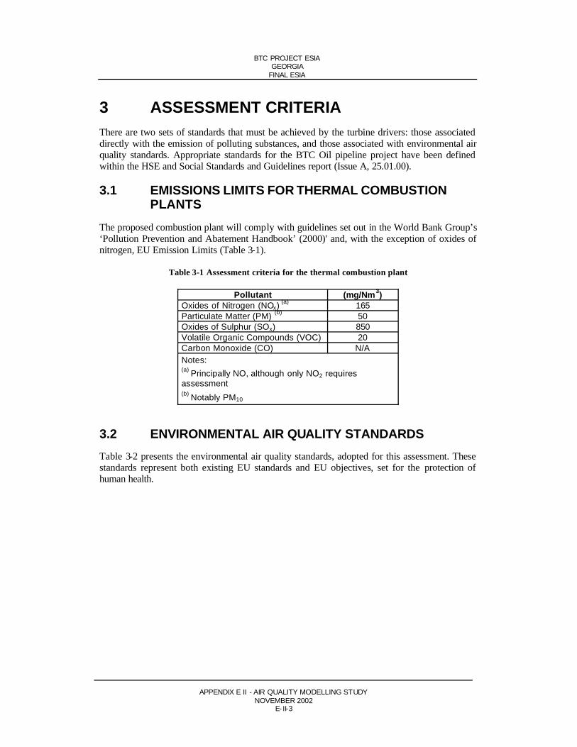
3 ASSESSMENT CRITERIAThere are two sets of standards that must be achieved by the turbine drivers: those associated directly with the emission of polluting substances, and those associated with environmental air quality standards. Appropriate standards for the BTC Oil pipeline project have been defined within the HSE and Social Standards and Guidelines report (Issue A, 25.01.00).
3.1 EMISSIONS LIMITS FOR THERMAL COMBUSTION PLANTS
The proposed combustion plant will comply with guidelines set out in the World Bank Group’s ‘Pollution Prevention and Abatement Handbook’ (2000)' and, with the exception of oxides of nitrogen, EU Emission Limits (Table 3-1).
Table 3-1 Assessment criteria for the thermal combustion plant
Pollutant (mg/Nm3)Oxides of Nitrogen (NOx) (a) 165Particulate Matter (PM) (b) 50Oxides of Sulphur (SOx) 850Volatile Organic Compounds (VOC) 20Carbon Monoxide (CO) N/ANotes:(a) Principally NO, although only NO2 requires assessment(b) Notably PM10
3.2 ENVIRONMENTAL AIR QUALITY STANDARDSTable 3-2 presents the environmental air quality standards, adopted for this assessment. These standards represent both existing EU standards and EU objectives, set for the protection of human health.

BTC PROJECT ESIAGEORGIA
FINAL ESIA
APPENDIX E II - AIR QUALITY MODELLING STUDYNOVEMBER 2002
E- II-4
Table 3-2 EU ambient air quality assessment criteria
Pollutant AssessmentCriteria ( g/m3)
Averaging Period Percentile
NO2(a) 200
401 hourAnnual mean
99.8th
CO (b) 11,600 Running 8 hour 100th
PM10(c) 50
4024 hourAnnual mean
90.4th
SO2(c) 350
1251 hour24 hour
99.7th
99.2th
Notes:(a) EU Directive to be achieved by 31 December 2005(b) EU Directive to be achieved by 31 December 2003(c) EU Directive to be achieved by 31 December 2004

BTC PROJECT ESIAGEORGIA
FINAL ESIA
APPENDIX E II - AIR QUALITY MODELLING STUDYNOVEMBER 2002
E- II-5
4 AMBIENT AIR QUALITYIn order to assess the proposed thermal combustion plants’ potential for impact upon the local air quality, it is necessary to determine the existing ambient air quality.
Although no ambient air quality data is ava ilable at the time of writing, it is expected, owing to the absence of any major polluting sources, that existing concentrations within the atmospheric boundary layer would be very low, and therefore have not been considered in an additive context with modelled data.

BTC PROJECT ESIAGEORGIA
FINAL ESIA
APPENDIX E II - AIR QUALITY MODELLING STUDYNOVEMBER 2002
E- II-6
5 INDICATIVE STACK HEIGHTSIndicative stack heights have been calculated using recognised industrial methods; Technical Guidance Note D1 (1993). The input parameters for each thermal power plant are presented in Table 5-1 below. D1 provides (approximately) a suitable stack height for a point source. However, the simplistic nature of these calculations should be recognised, and values calculated only form the basis of more accurate dispersion modelling, which is presented in the subsequent sections.
D1 calculations for each plant type have been included with this document as a PDF file. These spreadsheets also present useful information regarding the release characteristics of each plant option.
Table 5-1 Input parameters for D1 stack height determination
Input Parameters (a) (b)
Exhaust Gas Flow (kg/s) 34.7Temperature of exhaust gas (K) 784Moisture Content of Stack (%) 8.3Oxygen Content of Stack (%) 14.4SOx emission (mg/Nm3) (c) 91NOx emission (mg/Nm3) 165PM emission (mg/Nm3) 18CO emission (mg/Nm3) 64Discharge Velocity (m/s) 27.2Notes:(a) Parameters applicable to one Solar Mars 100 gas turbine (of which there are four active and one standby at each pump station)(b) Reference conditions (N): 15% oxygen, dry, 273K, 101.3 kPa(c) Based upon a 0.2% sulphur content of the fuel.

BTC PROJECT ESIAGEORGIA
FINAL ESIA
APPENDIX E II - AIR QUALITY MODELLING STUDYNOVEMBER 2002
E- II-7
6 INTRODUCTION TO AIR DISPERSIONMODELLING
In order to assess the predicted process contribution of the turbine drivers against relevant air quality standards and to optimise the height of each stack associated with the proposed facility, an atmospheric dispersion modelling study has been carried out using the AtmosphericDispersion Modelling System Version 3 (ADMS) model. This computer-based model predicts the dispersion of operational emissions from a specific source (ie a stack) and the subsequent concentrations over a grid of receptor points.
Using the information contained within a meteorological dataset and appropriate stack discharge parameters, the ADMS model computes the ground level concentrations associated with each hourly value at each point within the specified study area. In combination with its frequency, it also computes the long-term average or percentile ground level concentration at each point.
The values computed at these points can be directly compared to the legislative standards and objectives, and can therefore determine an acceptable stack height for the emission source.
6.1 DISPERSION MODEL INPUT DATAInput data required for ADMS consists of exhaust gas release characteristics, meteorological conditions and information on nearby structures and local topography.
6.1.1 Exhaust gas release characteristicsPlume dispersion and subsequent maximum ground level concentrations resulting fromemissions from the thermal power plant will be governed principally by the followingparameters:
Meteorological conditions: eg wind speed, wind direction and depth of the atmospheric boundary layer
Temperature of exhaust gas: a higher exhaust gas temperature will result in the plume possessing a greater thermal buoyancy and improved dispersion
Concentration of identified the concentration of the identified emissions will affect gaseous species in the the degree of subsequent ground level concentration exhaust gas:

BTC PROJECT ESIAGEORGIA
FINAL ESIA
APPENDIX E II - AIR QUALITY MODELLING STUDYNOVEMBER 2002
E- II-8
Volume flow rate of the effect of an increase in volume flow rate willexhaust gas: generally be two fold:
i. an increase in mass emission rates and subsequent ground level concentrations
ii. an increase in exit velocity which will result inimproved plume dispersion
ADMS input data for the thermal power plant is summarised in Table 6-1.
Table 6-1 Dispersion model input parameters
Input Parameter Solar Mars 100Internal Stack Diameter (m)Discharge Temperature at Stack Exit (K)Exit Velocity at Stack Discharge (m/s)Total Volume Flow Rate at Stack Discharge (m3/s)Moisture Content of Exhaust Gas (%)Oxygen Content of Exhaust Gas (%)Discharge density (kg/m3)NOX Mass Flow (g/s)SO2 Mass Flow (g/s) (b)
PM Mass Flow (g/s)CO Mass Flow (g/s)
1.9784
27.1578.88.28
14.370.454.492.480.491.74
(a) Parameters shown represent a single turbine (of which four will operate simultaneous during peak export, a fifth on standby)(b) Based upon 0.2% sulphur content by weight
6.1.2 Meteorological conditionsFor dispersion modelling, a meteorological data set comprising hourly sequential data for a period of 365 days has been obtained from Tbilisi Airport. The data allows the spatial variation of pollutant concentrations, as the plume migrates from the stack, to be explored under a wide range of locally representative conditions.
Meteorological data from Tbilisi was applied for dispersion modelling of both pump station sites. Measurements collected at this station are considered the most appropriate for this study as they have been collected in a climatically similar locality, and offer the best data capture of regionally available data sets.
Wind conditions near to the study site are presented in Figure E-1, as a wind rose. The wind rose shows that there is little deviation, in terms of both wind speed and direction, from the average or typical condition. The prevailing wind direction is north-westerly (300), with speeds in excess of 8m/s. This suggests that the plume would predominantly disperse in a south-easterly direction (120).

BTC PROJECT ESIAGEORGIA
FINAL ESIA
APPENDIX E II - AIR QUALITY MODELLING STUDYNOVEMBER 2002
E- II-9
Figure 1
6.1.3 Structures within the vicinityThe proposed thermal power plant enclosure and other surrounding structures may have an effect on the pattern of plume dispersion and subsequent ground level concentrations. It has been assumed that the only significant structure at the pumping stations would be the ‘pump house’ (initial modelling runs have demonstrated that site structures of equal to or less than 10 m height do not significantly affect gas dispersion from stacks over 15m in height).
6.1.4 Local topographyTopography may also have a significant influence on the dispersion of emissions andsubsequent ground level concentrations. It has been assumed that major topographical features do not exist at either of the pump station sites. Minor undulation of landforms is accounted for in the definition of ‘surface roughness’ within the model.
6.1.5 Grid sizeThe user can define the area over which concentrations will be predicted, in terms of a regular Cartesian Grid. A larger grid size will enable examination of dispersion over a greater area, yet will result in a decrease in the precision of the predicted ground level concentrations. Following initial testing, an optimum grid size of approximately 1.5km2 was chosen for this study.

BTC PROJECT ESIAGEORGIA
FINAL ESIA
APPENDIX E II - AIR QUALITY MODELLING STUDYNOVEMBER 2002
E- II-10
6.1.6 Assumptions
Composition of NOX generated by turbine plant
During operation of the proposed thermal combustion plant, NOx will be released to theatmosphere as a result of distillate fuel combustion. In practice, typically 5-10% of the NOx
emitted from turbines is expected to be in the form of NO2 (the species of interest) at the point of discharge (ie stack exit), the remainder being nitric oxide (NO). NO is a relatively innocuous substance, but it is of interest as a precursor to NO2.
Conversion of NO to NO2 takes place in the atmosphere under the influence of several factors, primarily the availability of ozone (O3) and atomic oxygen (O). NO reacts with ozone or atomic oxygen forming NO2, the rate of conversion governed mainly by atmospheric conditions and the degree of availability of atmospheric oxidants.
Conversion of NO to NO2 is significant with respect to locations within 5-10km of the proposed combustion plant. However, the chemistry of this conversion is complex and subject to many influences, and therefore it is not possible to accurately predict the rate of conversion of NO to NO2.
Warren Spring Laboratory Report LR693(AP)M (1993) supports the use of a NOx:NO2 ratio of 0.5 for power station emissions up to a distance of 50km (beyond which it reverts to 0.85). A study by Janssen (1988) reaches conclusions generally consistent with Warren SpringLaboratory, stating that at a distance of 5km from source (but depending on atmospheric stability, prevailing ozone concentration, wind speed and solar radiation), conversion of NO2
from NO may vary from less than 20% (stable atmosphere) to up to 50% (unstable atmosphere).
It is therefore considered conservative to assume a NOx:NO2 conversion ratio of 0.5 within the study area for the assessment of the potential for impact on local air quality (ie 50% of the NOx
released is assumed to be present as NO2). As this assumption is regarded as being conservative, it is likely to lead to a higher estimation of ground level NO2 concentration than would occur in practice.
SO2
As noted earlier, turbine drivers will operate on a distillate fuel generated from the exported crude by a crude topping plant. Early assays of the mainline crude have indicated that a sulphur content of approximately 0.07% is to be expected, but may (with particular blends of exported crude) be as high as 0.15%. To maintain a reasonable worst case approach, it has been assumed that the distillate fuel for turbine drivers will have a sulphur content of 0.2%

BTC PROJECT ESIAGEORGIA
FINAL ESIA
APPENDIX E II - AIR QUALITY MODELLING STUDYNOVEMBER 2002
E- II-11
7 TURBINE DRIVER STACK HEIGHTIndicative stack heights have been calculated using Technical Guidance Note D1 (1993). D1 provides (approximately) a suitable stack height for a point source. However, the simplistic nature of these calculations should be recognised, and the values calculated only provide a starting point for more accurate dispersion modelling.
Consequent confirmation of stack heights indicated by D1 calculations has indicated that a stack height of 28m above ground level for each turbine driver provides appropriate dispersion of emissions (as discussed in the following Section).

BTC PROJECT ESIAGEORGIA
FINAL ESIA
APPENDIX E II - AIR QUALITY MODELLING STUDYNOVEMBER 2002
E- II-12
8 DISPERSION MODELLING RESULTS
8.1 SHORT TERM CONCENTRATIONSTable 8-1 presents the short-term modelled ground level concentrations of study species,resulting from two thermal combustion plants located in Georgia, PSG1 and PSG2. Theproposed stack height of 28m for each turbine provides ground level concentrations of modelled species, which comply with EU short-term standards and objectives. The isopleths (ie, patternsof dispersion) are displayed in Attachment 1.
Table 8-1 Short-term dispersion modelling results
Maximum Modelled Concentration
( g/m3)
Pollutant
PS G1 PS G2
AssessmentCriteria( g/m3)
AveragingPeriod
Percentile
NO2(a) 136 127 200 1 hour 99.8th
CO (b) 91 87 11,600 Running 8 hour
100th
PM10(c) 5 5 50 24 hour 90.4th
SO2(c) 138
5713853
350125
1 hour24 hour
99.7th
99.2th
Notes:(a) EU Directive to be achieved by 31 December 2005(b) EU Directive to be achieved by 31 December 2003(c) EU Directive to be achieved by 31 December 2004
8.2 LONG TERM CONCENTRATIONSTable 8-2 presents the long-term dispersion modelling results for the two thermal combustion plants located in Georgia, PS G1 and PS G2. Similarly, a stack height of 28m for each turbine provides ground level concentrations of modelled species, which comply with current and proposed EU standards. The isopleths are displayed in Attachment 1.
Table 8-2 Long-term dispersion modelling results
MaximumModelled
Concentration( g/m3)
Pollutant
PS G1 PS G2
AssessmentCriteria( g/m3)
AveragingPeriod
Percentile
NO2(a) 15 8 40 Annual Mean
PM10(b) 2 2 40 Annual Mean
Notes:(a) EU Directive to be achieved by 31 December 2005(b) EU Directive to be achieved by 31 December 2004

BTC PROJECT ESIAGEORGIA
FINAL ESIA
APPENDIX E II - AIR QUALITY MODELLING STUDYNOVEMBER 2002
E- II-13
9 CONCLUSIONAtmospheric emissions for turbine drivers from two proposed pumping stations in Georgia, have been calculated and suitable stack heights proposed. D1 Stack height determination methodology was used to attain initial stack heights, followed by atmospheric dispersionmodelling to ensure compliance with EU air quality standards and objectives. Stack heights are as follows:
Pump Station 1 (PS G1): 28 metres above ground level, for all Solar Mars 100 gas turbines
Pump Station 2 (PS G2): 28 metres above ground level, for all Solar Mars 100 gas turbines

BTC PROJECT ESIAGEORGIA
FINAL ESIA
APPENDIX E II - AIR QUALITY MODELLING STUDYNOVEMBER 2002
E- II-14
ATTACHMENT 1 - ISOPLETHSPump Station PS G1
Hourly 99.8th percentile nitrogen oxide concentrations for pump station PS G1 (KP 3.6)
Note: NO2 assumed to represent 50% of the modelled concentration above.
1600 1800 2000 2200 2400 2600 2800 3000
Metres
1000
1200
1400
1600
1800
2000
2200
2400
120
140
160
180
200
220
240
260PS-G1

BTC PROJECT ESIAGEORGIA
FINAL ESIA
APPENDIX E II - AIR QUALITY MODELLING STUDYNOVEMBER 2002
E- II-15
Mean annual nitrogen oxide concentrations for pump station PS G1 (KP 3.6)
Note: NO2 assumed to represent 50% of the modelled concentration above.
1600 1800 2000 2200 2400 2600 2800 3000
Metres
1000
1200
1400
1600
1800
2000
2200
2400
2
4
6
8
10
12
14
PS-G1

BTC PROJECT ESIAGEORGIA
FINAL ESIA
APPENDIX E II - AIR QUALITY MODELLING STUDYNOVEMBER 2002
E- II-16
Hourly 99.7th percentile sulphur dioxide concentrations for pump station PS G1 (KP 3.6)
1600 1800 2000 2200 2400 2600 2800 3000
Metres
1000
1200
1400
1600
1800
2000
2200
2400
20
40
60
80
100
120PS-G1

BTC PROJECT ESIAGEORGIA
FINAL ESIA
APPENDIX E II - AIR QUALITY MODELLING STUDYNOVEMBER 2002
E- II-17
Daily 99.2th percentile sulphur dioxide concentrations for pump station PS G1 (KP 3.6)
1600 1800 2000 2200 2400 2600 2800 3000
Metres
1000
1200
1400
1600
1800
2000
2200
2400
20
25
30
35
40
45
50
55PS-G1

BTC PROJECT ESIAGEORGIA
FINAL ESIA
APPENDIX E II - AIR QUALITY MODELLING STUDYNOVEMBER 2002
E- II-18
Mean hourly particulate matter concentrations for pump station PS G1 (KP 3.6)
1600 1800 2000 2200 2400 2600 2800 3000
Metres
1000
1200
1400
1600
1800
2000
2200
2400
0.2
0.4
0.6
0.8
1.0
1.2
1.4
1.6
PS-G1

BTC PROJECT ESIAGEORGIA
FINAL ESIA
APPENDIX E II - AIR QUALITY MODELLING STUDYNOVEMBER 2002
E- II-19
Daily 90.4th percentile particulate matter concentrations for pump station PS G1 (KP 3.6)
1600 1800 2000 2200 2400 2600 2800 3000
Metres
1000
1200
1400
1600
1800
2000
2200
2400
1.5
2.0
2.5
3.0
3.5
4.0
4.5
5.0PS-G1

BTC PROJECT ESIAGEORGIA
FINAL ESIA
APPENDIX E II - AIR QUALITY MODELLING STUDYNOVEMBER 2002
E- II-20
Running 8 hour mean carbon monoxide concentrations for pump station PS G1 (KP 3.6)
1600 1800 2000 2200 2400 2600 2800 3000
Metres
1000
1200
1400
1600
1800
2000
2200
2400
20
30
40
50
60
70
80
90
PS-G1
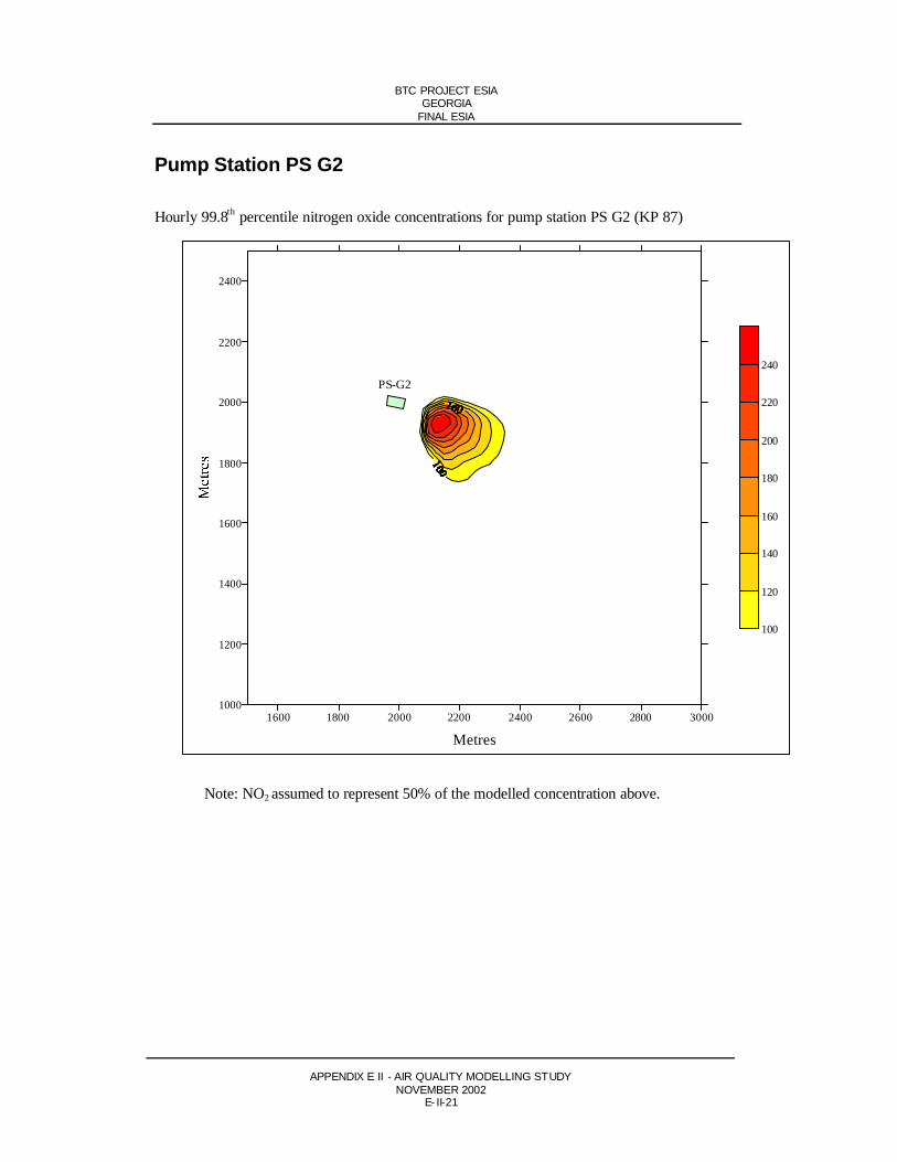
BTC PROJECT ESIAGEORGIA
FINAL ESIA
APPENDIX E II - AIR QUALITY MODELLING STUDYNOVEMBER 2002
E- II-21
Pump Station PS G2
Hourly 99.8th percentile nitrogen oxide concentrations for pump station PS G2 (KP 87)
Note: NO2 assumed to represent 50% of the modelled concentration above.
1600 1800 2000 2200 2400 2600 2800 3000
Metres
1000
1200
1400
1600
1800
2000
2200
2400
100
120
140
160
180
200
220
240
PS-G2

BTC PROJECT ESIAGEORGIA
FINAL ESIA
APPENDIX E II - AIR QUALITY MODELLING STUDYNOVEMBER 2002
E- II-22
Mean annual nitrogen oxide concentrations for pump station PS G2 (KP 87)
Note: NO2 assumed to represent 50% of the modelled concentration above.
1600 1800 2000 2200 2400 2600 2800 3000
Metres
1000
1200
1400
1600
1800
2000
2200
2400
2
4
6
8
10
12
14
PS-G2

BTC PROJECT ESIAGEORGIA
FINAL ESIA
APPENDIX E II - AIR QUALITY MODELLING STUDYNOVEMBER 2002
E- II-23
Hourly 99.7th percentile sulphur dioxide concentrations for pump station PS G2 (KP 87)
1600 1800 2000 2200 2400 2600 2800 3000
Metres
1000
1200
1400
1600
1800
2000
2200
2400
20
40
60
80
100
120PS-G2

BTC PROJECT ESIAGEORGIA
FINAL ESIA
APPENDIX E II - AIR QUALITY MODELLING STUDYNOVEMBER 2002
E- II-24
Daily 99.2th percentile sulphur dioxide concentrations for pump station PS G2 (KP 87)
1600 1800 2000 2200 2400 2600 2800 3000
Metres
1000
1200
1400
1600
1800
2000
2200
2400
15
20
25
30
35
40
45
50PS-G2

BTC PROJECT ESIAGEORGIA
FINAL ESIA
APPENDIX E II - AIR QUALITY MODELLING STUDYNOVEMBER 2002
E- II-25
Mean hourly particulate matter concentrations for pump station PS G2 (KP 87)
1600 1800 2000 2200 2400 2600 2800 3000
Metres
1000
1200
1400
1600
1800
2000
2200
2400
0.2
0.4
0.6
0.8
1.0
1.2
1.4
1.6
PS-G2

BTC PROJECT ESIAGEORGIA
FINAL ESIA
APPENDIX E II - AIR QUALITY MODELLING STUDYNOVEMBER 2002
E- II-26
Daily 90.4th percentile particulate matter concentrations for pump station PS G2 (KP 87)
1600 1800 2000 2200 2400 2600 2800 3000
Metres
1000
1200
1400
1600
1800
2000
2200
2400
1.5
2.0
2.5
3.0
3.5
4.0
4.5
5.0PS-G2

BTC PROJECT ESIAGEORGIA
FINAL ESIA
APPENDIX E II - AIR QUALITY MODELLING STUDYNOVEMBER 2002
E- II-27
Running 8 hour mean carbon monoxide concentrations for pump station PS G2 (KP 87)
1600 1800 2000 2200 2400 2600 2800 3000
Metres
1000
1200
1400
1600
1800
2000
2200
2400
10
20
30
40
50
60
70
80
PS-G2

BTC PROJECT ESIAGEORGIA
FINAL ESIA
APPENDIX B I - GEORGIA HGA APPENDIX 3 PA RT 3NOVEMBER 2002
APPENDIX B POLICY AND LEGAL FRAMEWORK
ANNEX I GEORGIA HGA APPENDIX 3 PART 3ANNEX II GETTING HSE RIGHT

BTC PROJECT ESIAGEORGIA
FINAL ESIA
APPENDIX B I - GEORGIA HGA APPENDIX 3 PA RT 3NOVEMBER 2002
B-I-1
Appendix B Annex I
Georgia HGA Appendix 3 Part 3
ENVIRONMENTAL STANDARDS3.1 With respect to minimising potential disturbances to the environment, including the
surface, subsurface, sea, air, watercourses and reservoirs, lakes, flora, fauna,landscapes, ecosystems and other natural resources and property, the MEPParticipants shall, in conducting all Pipeline Activities and with respect to theFacilities, conform to the environmental standards and practices set forth in this Appendix 3 as well as those generally observed by the international community with respect to Petroleum pipeline projects comparable to the Project, but in no event shall such environmental standards and practices be less stringent than the relevant standards and practices applied in the Netherlands (and, with respect tomountainous and earthquake-prone terrain as well as whenever the Netherlands has no relevant standard or practice, the relevant standards or practices, if any, of Austria) in respect of comparable projects (the “Environmental Standards”). For the avoidance of doubt, whenever the Environmental Standards refer to or aredrawn from the standards and practices of any particular country or jurisdiction (such as the Netherlands or Austria), those environmental standards and practices:
(i) do not include the laws of that country or jurisdiction defining orestablishing the legal standard of liability (such as negligence, strict liability or the like) of Persons for harm arising from any environmental events, occurrences or noncompliance, it being agreed that the provisions of the Agreement (including, in particular, Articles 10 and 12) relating to what constitutes, and the consequences of, the MEP Participants’ breach ofobligations shall apply;
(ii) do not include the regulatory administrative structure or procedures(including those for licensing, permitting and regulatory approvals) of that country or jurisdiction, it being agreed that the regulatory administrative structure and procedures, including environmental permitting as set forth in Section 7.3 of the Agreement, of Georgia shall apply;
(iii) in those instances in which the particular environmental standard or practiceassumes or is based upon technical standards or practices of a country or jurisdiction which are not identical or comparable to the ApplicableTechnical Standards, the MEP Participants shall either (a) follow those standards and practices which are compatible with the Applicable Technical Standards in order to achieve environmental protections substantiallycomparable to those of the country or jurisdiction or (b) comply with such country or jurisdiction’s environmental standard or practice to the extentreasonably practicable under the circumstances, taking into account the use of the Applicable Technical Standards; and

BTC PROJECT ESIAGEORGIA
FINAL ESIA
APPENDIX B I - GEORGIA HGA APPENDIX 3 PA RT 3NOVEMBER 2002
B-I-2
(iv) do not include environmental standards and practices beyond thoseapplicable to Petroleum pipelines and pipeline operations.
3.2 The MEP Participants shall promptly notify the Government of all emergencies and other events (including explosions, leaks, and spills) occurring in relation to Pipeline Activities that result in or threaten serious personal injury, loss of life, or significant damage to the environment or property. Such notice shall include a summary description of the circumstances, and steps taken and planned by the MEP Participants to control and remedy the situation. The MEP Participants shall provide such additional reports to the Government as are necessary to keep it apprised of the effects of such events and the course of all actions taken to prevent further loss and to mitigate deleterious effects. At the Government’s sole cost, risk and expense, and in a manner which does not interfere with the MEP Participants’ activities undertaken in response to an emergency or other event as hereindescribed, the designated representative(s) of the Government shall have the right to visit the scene and monitor the responsive or remedial activities of the MEP Participants to confirm compliance with this Code of Practice and the Agreement to which this Code of Practice is appended.
3.3 If any regional or intergovernmental authority having jurisdiction enacts orpromulgates environmental standards or practices relating to the Facilities, Pipeline Activities or areas where Pipeline Activities occur, the MEP Participants and the Government will confer respecting the possible impact thereof on the Project, but in no event shall the Project be subject to any such environmental standards or practices to the extent they are different from, in addition to, or more stringent than the Environmental Standards.
3.4 Prior to the selection of the general location of the Facilities, a review ofenvironmental conditions and the potential risks to the environment associated with Pipeline Activities shall be completed. This will consist of a scoping study and a risk assessment. The scoping study will be the basis for the environmental impact assessment (“EIA”) further described in Section 3.6 hereof. The risk assessment will serve to highlight potential risks and costs impacts to the engineering design requirements of the Project.
3.5 After completion of the scoping study and risk assessment described in Section 3.4, the MEP Participants shall cause to be conducted a contaminated land baseline study (the “Baseline Study”) to provide a qualitative assessment of the existing pollution and contamination in the areas within the Territory relevant to Pipeline Activities as of the Effective Date. The Baseline Study shall include:
(i) a desk study review of the relevant and available information;
(ii) an audit of relevant existing operations and practices and the collection of relevant environmental data from the areas surrounding the location of the Facilities, including information on:
(a) surface and subsurface geology;(b) geomorphology;(c) rock permeability and the presence of aquifers;(d) assessment of existing quality of surface waters;
BTC PROJECT ESIAGEORGIA
FINAL ESIA
APPENDIX B I - GEORGIA HGA APPENDIX 3 PA RT 3NOVEMBER 2002
B-I-3
(e) the effect of any existing contamination on flora, fauna, landscapes and ecosystems; and
(f) a qualitative assessment of any pollution, environmental damage and contamination in respect of the Facilities.
3.6 Upon completion of the Baseline Study, the MEP Participants shall cause an EIA of Pipeline Activities and associated operations to be conducted with respect to potential environmental impacts to the Territory (whether from Pipeline Activities within or without the Territory). The EIA shall include:
(i) a project description;
(ii) an environmental and socio-economic description of the relevant areas of possible impact;
(iii) an evaluation of impact to the environment of the proposed construction and operation of the Facilities, including an estimate of those emissions and discharges into the environment (eg, associated air emissions, aqueous discharges and solid waste produced) that are reasonably foreseeable;
(iv) a plan for the identification and implementation of practicable mitigation measures for each identified impact;
(v) an assessment of the environmental risks associated with Pipeline Activities; and
(vi) the formulation of a monitoring programme to verify that mitigationmeasures are effective, and in the event that additional impacts are identifiedto ensure that additional appropriate mitigation measures are effected;provided, however, that said monitoring programme shall provide forGovernment participation at the Government’s sole cost, risk and expense, which participation shall not interfere with Project Activities; and provided further, that in recognition that the Government will be conducting its own monitoring of the Project to assure environmental compliance, the MEP Participants will cooperate with the Government in respect of such Project monitoring, but the foregoing general duty of cooperation shall not vary any terms of the Agreement (including its Appendices).
3.7 Prior to the completion of the Facilities and in relation to Pipeline Activities, a plan for Petroleum spill response capability (“Spill Response Plan”) as to spills within or that could affect the Territory will be created and implemented by the MEP Participants. The Spill Response Plan will include:
(i) environmental mapping of habitats vulnerable to potential Petroleum spills in the entire MEP System;
(ii) situational scenarios of potential spillages and responses, taking intoconsideration local circumstances;
(iii) plans for the provision of relevant Petroleum spill clean up equipment, materials and services;

BTC PROJECT ESIAGEORGIA
FINAL ESIA
APPENDIX B I - GEORGIA HGA APPENDIX 3 PA RT 3NOVEMBER 2002
B-I-4
(iv) plans for the deployment of relevant equipment and emergency response notification details of the organisation required to handle Petroleum spill response; and
(v) plans for the treatment and disposal of resulting contaminated materials.
3.8 Each of the scoping study, risk assessment, Baseline Study, EIA and SpillResponse Plan (collectively, the “Environmental Strategy Product”) shall beprepared by one or more recognised independent international environmentalconsulting firms selected by the MEP Participants and approved by theGovernment, such approval not to be unreasonably withheld or delayed. In this regard, the MEP Participants’ choice for the recognised independent international environmental consulting firm shall be deemed approved by the Government if, by not later than twenty (20) days after such choice is notified to the Government, the MEP Participants have received no written objection (with the reason(s) for any such objection fully set forth) to their choice. The costs of the items constitutingthe Environmental Strategy Product, and implementation of the environmentalstrategy reflected in the EIA and the Spill Response Plan, shall be borne by the MEP Participants except that the Government shall be liable for all costs associated with its official and technical representatives.
3.9 The development and completion of the Baseline Study, the EIA and the Spill Response Plan shall be subject to the following procedures to ensure that theyrepresent implementation of an appropriate environmental strategy with respect to the Project:
(i) The consulting firm(s) involved and representatives of the MEP Participants shall, at the request of the Government, consult with the official andtechnical representatives of the Government, at reasonable times and places, during the preparation of the Baseline Study, the EIA and the Spill Response Plan.
(ii) The Baseline Study, the EIA and the Spill Response Plan shall each be subject to approval of the Government in accordance with the following procedures:
(a) The Baseline Study, the EIA (with executive summary demonstrating adequate response to public concerns, as described below) and the Spill Response Plan shall each be submitted to the Government upon its completion, which completion of the Baseline Study and EIA shall be prior to commencement of construction activities and provided that the MEP Participants shall provide the Government no less than thirty (30) days prior notice before making any such submission(s). The Government shall approve each such item if it satisfies therequirements of this Appendix 3.
(b) If the Government requires clarification of any portion of the Baseline Study, the EIA or the Spill Response Plan, or determines that it has not satisfied the requirements of this Appendix 3, it shall submit its specific concerns or questions to the MEP Participants in writing within thirty (30) days of receipt of the item in question.

BTC PROJECT ESIAGEORGIA
FINAL ESIA
APPENDIX B I - GEORGIA HGA APPENDIX 3 PA RT 3NOVEMBER 2002
B-I-5
(c) The Baseline Study, the EIA or the Spill Response Plan, as the case may be, shall be deemed approved by the Government if, within thirty (30) days after having been submitted to the Government, the MEP Participants have received no written submission of additionalconcerns or questions. If the Government submits specific concerns or questions, the item in question shall be deemed approved if, within thirty (30) days after the response to such concerns or questions is submitted to the Government, the MEP Participants have received no written submission of concerns or questions with respect to suchresponse.
(d) If the Government disapproves of any of the Baseline Study, the EIA or the Spill Response Plan and the MEP Participants believe that the Government has unreasonably withheld its acceptance, then the MEP Participants shall so notify the Government and the Parties shall attempt to amicably resolve any dispute. Failing resolution of any such dispute within fifteen (15) days of the receipt of such notice by the Government, the MEP Participants may cause the dispute to be resolved in accordance with the provisions of Article 17 of the Agreement.
(iii) The EIA shall be subjected to public review and comment in accordance with the following procedures:
(a) Affected public and non-governmental organisations will be notified about the nature of the operation of the Facilities during thedevelopment of the EIA through dissemination of information to these organisations through meetings and exhibitions.
(b) Following the completion of the EIA, the public will be provided with information on the environmental aspects of the Project to enable it to comment with respect thereto. To facilitate this process the EIA and an executive summary (in the Georgian language) will be madeavailable in a public place for review and comments; additionally an information copy of the executive summary shall be submittedsimultaneously to the Government.
(c) A maximum of sixty (60) days will be allowed for public comments, which will be provided to the Government by the MEP Participants within thirty (30) days after the expiration of said sixty (60)-dayperiod. Demonstration that the MEP Participants have reasonably addressed public concerns (through modification of the EIA, ifnecessary) will be included in a final executive summary that will be submitted to the Government.

BTC PROJECT ESIAGEORGIA
FINAL ESIA
APPENDIX B I - GEORGIA HGA APPENDIX 3 PA RT 3NOVEMBER 2002
B-I-6
3.10 Creation of the Environmental Strategy Product shall include and take account of and implementation of the environmental strategy reflected therein shall be inaccordance with, the Environmental Standards and shall take into account the Applicable Technical Standards, as appropriate. Creation of the EIA shall also be in accordance with the principles of EC Directive 85/337/EEC (as amended by EC Directive 97/11/EC) and its conclusions will be based upon the following general environmental principles:
(i) there shall be no discharging of Petroleum;
(ii) waste Petroleum, sludge, pigging wastes, polluted ballast waters and other wastes will either be recycled, treated, burned, or buried employing the best practicable environmental option;
(iii) all waste streams will be disposed of in an acceptable manner andconcentration; and
(iv) emission monitoring programs will be developed to ensure environmental compliance.
3.11 Once approved by the Government, the MEP Participants shall implement the mitigation and monitoring activities specified in the EIA. The results shall be published in reports available to the public and submitted to the appropriate State Authorities. The EIA monitoring programme shall be updated as required on an informal basis. Any disputes respecting the contents or implementation of the EIA monitoring programme shall be resolved in accordance with the provisions of Article 17 of the Agreement.
3.12 Any dispute as to implementation of the environmental strategy reflected in the Environmental Strategy Product shall be resolved in accordance with theprovisions of Article 17 of the Agreement.
3.13 Without limiting the generality of Article 10 or Article 12 of the Agreement, the MEP Participants shall not be liable for any environmental pollution orcontamination, damage, or other conditions if and to the extent the same were in existence on the Effective Date, which shall be deemed to include all conditions identified in the Baseline Study. The foregoing shall not preclude the MEPParticipants from later establishing, through one or more subsequent studiesprepared under the procedures applicable to the Baseline Study, the existence as of the Effective Date of other such conditions not identified by the Baseline Study, it being recognised that no study can be expected to identify all conditions that may exist.
3.14 By not later than thirty (30) days after any termination of this Agreement, the MEP Participants shall provide to the Government a written plan describing the proposed actions to be taken by them associated with the abandonment or other disposition of the Facilities (the “Abandonment Plan”). The Abandonment Plan shall address, among other things:
a) the removal of all surface installations;

BTC PROJECT ESIAGEORGIA
FINAL ESIA
APPENDIX B I - GEORGIA HGA APPENDIX 3 PA RT 3NOVEMBER 2002
B-I-7
b) the clearance of all waterways and marine areas of material and equipment posing a navigational hazard;
c) the drainage and proper disposition of any remaining Petroleum in the Facilities;
d) the extent the MEP Participants do not plan to remove and salvage saide) to the extent the MEP Participants do not plan to remove and salvage said
pipelines, the filling of all abandoned pipeline located offshore orunderwater with water or inert material, the sealing of such pipelines at the ends and the taking of such other action as may be reasonably necessary in order to result in any abandoned facilities being left in an environmentally safe condition;
f) the filling of all trenches, holes, and other surface depressions left by the removal of surface installations and such underground pipelines andinstallations as are removed by the MEP Participants for salvage;
g) the revegetation of the Pipeline Corridor consistent with the terrain features and other prevailing conditions in the subject area; and
h) the manner and techniques to be employed in accomplishing the foregoing activities consistent with the Environmental, Health and Safety Standards and/or Technical Standards, as applicable.
The Abandonment Plan shall be subject to approval by the Government, which approval shall not be unreasonably withheld or delayed. The Abandonment Plan shall be deemed approved by the Government if, within ninety (90) days afterhaving been submitted to the Government, the MEP Participants have received no written submission of concerns or questions. If the Government submits specific concerns or questions, the MEP Participants shall respond to same in writing and the Abandonment Plan, as same may have been adjusted or modified by said response, shall be deemed approved if, within thirty (30) days after the response to such concerns or questions is submitted to the Government, the MEP Participants have received no written submission of concerns or questions with respect to such response. If the Government disapproves of the Abandonment Plan and the MEP Participants believe that the Government has unreasonably withheld its acceptance, then the MEP Participants shall so notify the Government and the Parties shall attempt to amicably resolve any dispute. Failing resolution of any such dispute within thirty (30) days of receipt of such notice by the Government, the MEP Participants may cause the dispute to be resolved in accordance with the provisions of Article 17 of the Agreement. Once the Abandonment Plan has been approved or all disputes respecting same resolved, by not later than thirty-six (36) months after the later of the date of termination of this Agreement or approval by theGovernment of the Abandonment Plan, the MEP Participants shall be obligated to accomplish the abandonment of the Facilities in accordance with the Abandonment Plan. Said abandonment obligations are hereinafter referred to as the“Abandonment Obligations.”

BTC PROJECT ESIAGEORGIA
FINAL ESIA
APPENDIX B I - GEORGIA HGA APPENDIX 3 PA RT 3NOVEMBER 2002
B-I-8
3.15 Within thirty (30) days after the Government’s approval of the Abandonment Plan, as provided in Section 3.14 of Appendix 3, in order to financially secure theirAbandonment Obligations hereunder and without impairing their obligation toperform same, the MEP Participants shall provide the Government one or more irrevocable direct pay letters of credit (collectively, the “Letter of Credit”). The Letter of Credit shall (i) be in an aggregate amount to be reasonably agreed by the MEP Participants and the Government as a component of the Abandonment Plan, (ii) be issued to the Government by a financial institution(s) having a long-termunsecured senior debt rating of at least “A” or its equivalent by Standard & Poor’s Corporation, a division of the McGraw-Hill Companies, or “A2” or its equivalent by Moody’s Investors’ Service, Inc. at the time of issuance, or be otherwiseacceptable to the Government (the “Issuer”), (iii) be in form and substancereasonably acceptable to the Government, (iv) have a minimum term of one (1) year, (v) be for the benefit of the Government, (vi) automatically extend for a term of at least one (1) year or until the full performance in all material respects by the MEP Participants of the Abandonment Obligations and (vii) provide that the Issuer shall provide at least thirty (30) days prior written notice to the Government of any termination or non-renewal of the Letter of Credit. In the event the Abandonment Obligations remain unperformed and any existing Letter of Credit is not replaced by the MEP Participants in accordance with the foregoing procedures (but in an aggregate amount that reflects any reduction of the Letter of Credit for anyprevious drawings or for any reduction in the amount of estimated remainingAbandonment Obligations) by not later than fifteen (15) days prior to thetermination of the existing Letter of Credit, then, in order to assure completion of any Abandonment Obligations which remain outstanding, the Government shall be entitled to draw upon the Letter of Credit as of said fifteenth day prior to the notified termination date thereof up to an amount that is the Government’s good faith estimate of the remaining Abandonment Obligations for which the MEP Participants are liable under the Abandonment Plan, subject, however, toreimbursement by the Government to the MEP Participants of the amount, if any, by which the funds so withdrawn by the Government exceed the actual costsincurred by the Government to complete any unfulfilled Abandonment Obligations.
3.16 The following provisions shall apply with respect to the obligations of the MEP Participants for environmental matters after termination of this Agreement andperformance of the Abandonment Obligations:
i. After completion of the Abandonment Obligations the MEP Participants shall cause an environmental assessment similar in scope to, andprepared in accordance with the same standards as are applicable to, the Baseline Study (the “Preliminary Exit Study”) to be prepared by arecognised independent international environmental consulting firmselected by the MEP Participants and approved by the Government, such approval not to be unreasonably withheld or delayed. In this regard, the MEP Participants’ choice for the recognised independent international consulting firm shall be deemed approved by the Government if, by not later than twenty (20) days after such choice is notified to theGovernment, the MEP Participants have received no written objection (with the reason(s) for any such objection fully set forth) to their choice. If the Preliminary Exit Study is prepared at the request of theGovernment as contemplated above, it shall be delivered to the

BTC PROJECT ESIAGEORGIA
FINAL ESIA
APPENDIX B I - GEORGIA HGA APPENDIX 3 PA RT 3NOVEMBER 2002
B-I-9
Government within one hundred eighty (180) days after performance of the Abandonment Obligations.
ii. Once such study is prepared and delivered to the Government, it shall be subject to approval by the Government, which approval shall not be unreasonably withheld or delayed. The Preliminary Exit Study shall be deemed approved by the Government if, within thirty (30) days afterhaving been submitted to the Government, the MEP Participants have received no written submission of concerns or questions. If theGovernment submits specific concerns or questions, the Preliminary Exit Study shall be deemed approved if, within thirty (30) days after theresponse to such concerns or questions is submitted to the Government, the MEP Participants have received no written submission of concerns or questions with respect to such response. If the Government disapproves of the Preliminary Exit Study and the MEP Participants believe that the Government has unreasonably withheld its acceptance, then the MEPParticipants shall so notify the Government and the Parties shall attempt to amicably resolve any dispute. Failing resolution of any such dispute within thirty (30) days of the receipt of such notice by the Government, the MEP Participants may cause the dispute to be resolved in accordance with the provisions of Article 17 of the Agreement.
iii. Once the Preliminary Exit Study is approved or all disputes respecting same are resolved, the MEP Participants shall be obligated to continue to monitor those areas where Pipeline Activities occurred in order toidentify and remediate those adverse environmental impacts related to Pipeline Activities which may subsequently become evident. Suchmonitoring and remediation obligation shall continue for a period of two (2) years, at which time the above-stated provisions of this Section 3.16 respecting the Preliminary Exit Study shall apply for purposes ofpreparing a Final Exit Study. Once the Final Exit Study is prepared,submitted for Governmental approval and it has been approved by the Government, then from and after the end of said two-year period and completion of the activities, if any, called for in the Final Exit Study, theMEP Participants shall be released from any liability for environmental impacts with respect to or resulting from the Project and the Government shall indemnify, defend and hold harmless the Project Participants with respect to any claims of any third parties with respect thereto.
iv. If a Final Exit Study is performed and if said Final Exit Study, asapproved by the Government, indicates that there have been noenvironmental impacts of Pipeline Activities that have not beenremediated or otherwise appropriately addressed in accordance with this Appendix 3, or if impacts that are identified are remediated or otherwise appropriately addressed in accordance with such standards and this is reflected in an update to the Final Exit Study, then from and afterdelivery of the Final Exit Study (as so updated) to the Government, the MEP Participants shall be released from any liability for environmental impacts with respect to or resulting from the Project and the Government shall indemnify, defend and hold harmless the Project Participants with respect to any claims of any third parties with respect thereto.

BTC PROJECT ESIAGEORGIA
FINAL ESIA
APPENDIX B I - GEORGIA HGA APPENDIX 3 PA RT 3NOVEMBER 2002
B-I-10
3.17. In addition to their applicability to the MEP Participants, the provisions of this Appendix 3 shall apply with respect to each Project Participant other than an MEP Participant, and all of its actions, to the extent such actions constitute conduct or performance of Pipeline Activities.

Paper copies are uncontrolled. The controlled version is on the BP Intranet http://gbc.bpweb.bp.com/hse/policy/Hseright99
getting HSE right
a guide for BP managers
March 2001

Paper copies are uncontrolled. The controlled version is on the BP Intranet http://gbc.bpweb.bp.com/hse/policy/Hseright99
2
Contents
IntroductionBP’s Commitment to HSE PerformanceHSE Expectations
Key HSE Processes:
Delivering HSE AssuranceBehavioursHSE Risk ManagementCrisis and Emergency ManagementMajor Incident and High Potential Incident ReportingIncident Investigation GuidelinesHSE Performance Targets 16
HSE Reporting RequirementsJoint Ventures and other Operational RelationshipsHSE Reporting DefinitionsHealth ManagementHSE ToolboxRelated Policies and DocumentsGlossary (Definitions for superscripted words in the document)
AmendmentNumber
Date Section / Topic Authorised by
Issue 1.1 8 Jan 99 - P ElliotIssue 1.2 8 May 99 Minor changes to align with
printed (hard copy) versionP Elliot
Issue 1.3 March2001
Minor changes; company name amended to ‘BP’
L Callard

Paper copies are uncontrolled. The controlled version is on the BP Intranet http://gbc.bpweb.bp.com/hse/policy/Hseright99
3
Getting HSE right
A guide for BP managers
Introduction
Our goals...
BP will be distinctive worldwide in our pursuit and attainment of health, safety andenvironmental performance. BP’s Commitment to HSE Performance is one of the five Group Business Policies (Ethical Conduct, Employees, Relationships, HSE Performance, Control and Finance). It is our pledge to demonstrate respect for the natural environment and to work to achieve our goals of no accidents, no harm to people and no damage to the environment.
How we achieve them...
This Guide describes the BP HSE Management System Framework and the Key Processes which support the HSE Expectations to be adopted by all BP managers. These encompass the complete spectrum of health, safety and environmental risk management including personal security, technical/operational integrity of facilities and equipment, and product stewardship. They are the boundaries within which all BP managers must operate.
All Business Unit leaders (in BP Chemicals multi-business sites, the Works General Manager) must communicate the HSE Expectations to their teams and are accountable for delivery of HSE performance. Each business unit shall have documented systems in place to meet the Expectations, including justification, where necessary why certain Expectations are not applicable to that Business Unit.
What is the prize...?
Effective management processes that fulfil the intent of the HSE expectations will result in enhanced business unit performance, protection of our group reputation, improvement of our liability profile, and a distinctive leadership position in our industry and the world.
What the Framework provides...
The HSE management system framework provides a broad-based set of Expectations integrated into thirteen elements of accountability. This framework will help line managers focus on critical HSE needs, forecast and allocate resources, set direction for HSE activities, and consistently deliver improved HSE performance.
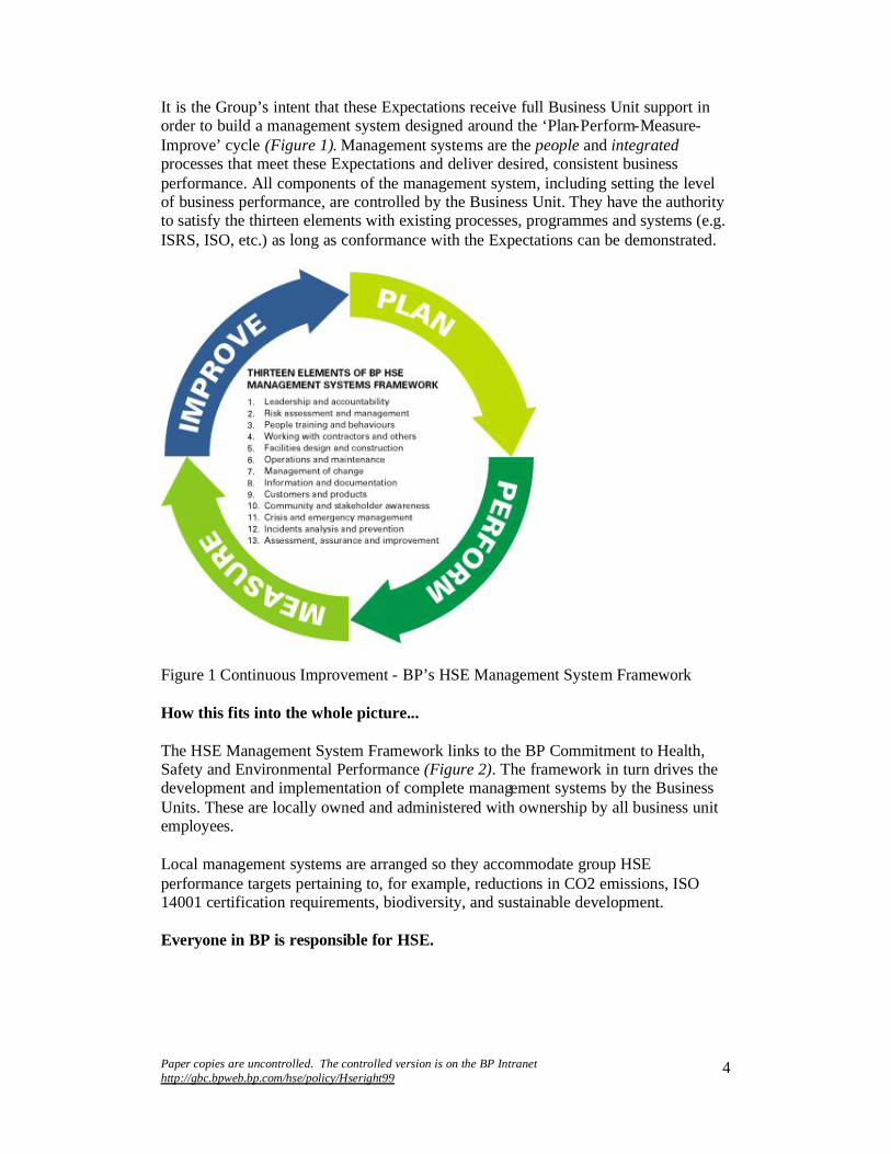
Paper copies are uncontrolled. The controlled version is on the BP Intranet http://gbc.bpweb.bp.com/hse/policy/Hseright99
4
It is the Group’s intent that these Expectations receive full Business Unit support in order to build a management system designed around the ‘Plan-Perform-Measure-Improve’ cycle (Figure 1). Management systems are the people and integratedprocesses that meet these Expectations and deliver desired, consistent business performance. All components of the management system, including setting the level of business performance, are controlled by the Business Unit. They have the authority to satisfy the thirteen elements with existing processes, programmes and systems (e.g. ISRS, ISO, etc.) as long as conformance with the Expectations can be demonstrated.
Figure 1 Continuous Improvement - BP’s HSE Management System Framework
How this fits into the whole picture...
The HSE Management System Framework links to the BP Commitment to Health, Safety and Environmental Performance (Figure 2). The framework in turn drives the development and implementation of complete management systems by the Business Units. These are locally owned and administered with ownership by all business unit employees.
Local management systems are arranged so they accommodate group HSE performance targets pertaining to, for example, reductions in CO2 emissions, ISO 14001 certification requirements, biodiversity, and sustainable development.
Everyone in BP is responsible for HSE.

Paper copies are uncontrolled. The controlled version is on the BP Intranet http://gbc.bpweb.bp.com/hse/policy/Hseright99
5
Figure 2 The BP HSE management system
How we learn from each other...
The HSE Toolbox will be maintained on the Intranet containing good operating processes/practices, knowledge and audit protocols. These show good demonstrated practice from around the BP Group, and should be referenced when developing Business Unit management systems. More importantly, business unit personnel are encouraged to contribute their good practices to the HSE Toolbox in order to promote sharing and adoption of lessons learned.
How we know it is being done effectively...
Business Unit leaders assure themselves and the Group Chief Executive that all relevant processes are in place and working effectively to manage HSE risks associated with their business activities. This is achieved through regular:
risk assessments and risk management programmes peer reviews, self-assessments and objective external assessments reviews of performance indicators against agreed targets

Paper copies are uncontrolled. The controlled version is on the BP Intranet http://gbc.bpweb.bp.com/hse/policy/Hseright99
6
HSE assurance is regularly discussed between Business Unit Leaders and their senior team. An assurance audit is periodically conducted to provide a review of key internal controls. In addition, an annual HSE assurance report is prepared summarizing progress and planned activities.
John MogfordGroup Vice President, HSE

Paper copies are uncontrolled. The controlled version is on the BP Intranet http://gbc.bpweb.bp.com/hse/policy/Hseright99
7
BP’s Commitment to Health, Safety and Environmental Performance
Everybody who works for BP, anywhere, is responsible for getting HSE right. Good HSE performance and the health, safety and security of everyone who works for us are critical to the success of our business.
Our goals are simply stated - no accidents, no harm to people, and no damage to the environment.
We will continue to drive down the environmental and health impact of our operations by reducing waste, emissions and discharges, and using energy efficiently. We will produce quality products that can be used safely by our customers.
We will:
consult, listen and respond openly to our customers, employees, neighbours, public interest groups and those who work with us
work with others - our partners, suppliers, competitors and regulators - to raise the standards of our industry
openly report our performance, good and bad recognize those who contribute to improved HSE performance
Our business plans include measurable HSE targets. We are all committed to meeting them.
John Browne HSE PolicyGroup Chief Executive January 1999

Paper copies are uncontrolled. The controlled version is on the BP Intranet http://gbc.bpweb.bp.com/hse/policy/Hseright99
8
BP 's Health, Safety and Environmental Expectations
BP's HSE Expectations are detailed within the thirteen elements of the HSE Management System Framework. These Expectations outline BP’s requirements for the management of:
safety and accident prevention plant and equipment integrity pollution prevention energy conservation personal, occupational and environmental health personal/physical security product stewardship sustainable development
In all our activities and operations, we will:
comply fully with all legal requirements and meet or exceed these Expectations wherever we operate in the world.
provide a secure working environment by protecting ourselves, our assets, and our operations against risk of injury, loss or damage from criminal or hostile acts.
ensure that all our employees, contractors and others are well informed, well trained, engaged and committed to the HSE improvement process. We recognize that safe operations depend not only on technically sound plant and equipment but on competent people and an active HSE culture, and that no activity is so important that it cannot be done safely.
regularly provide assurance that the processes in place are working effectively. While all BP employees and contractors are responsible for HSE performance, line management is accountable for understanding and managing HSE risks.
fully participate in hazard identification and risk assessments, Assurance Audits, and reporting of HSE results.
maintain public confidence in the integrity of our operations. We will openly report our performance and consult with people outside the company to improve our understanding of external and internal HSE issues associated with our operations.
expect that all parties working on BP’s behalf recognize that they can impact our operations and reputation, and must operate to our standards. We will assure ourselves that our contractors’ and others’ management systems fully support our Commitment to HSE Performance.
Addressing the full set of HSE Expectations is mandatory for every activity across the entire BP organization. The relevance, application and degree of implementation within a particular operation or Business Unit will be a function of:
the operational risk profile local and national regulatory requirements any voluntary HSE management programmes

Paper copies are uncontrolled. The controlled version is on the BP Intranet http://gbc.bpweb.bp.com/hse/policy/Hseright99
9
Managers are accountable for putting in place appropriate documented systems and processes for each Expectation, for ensuring continuing progress towards BP’s HSE goals and targets, and for confirming that these processes are effective via the HSE Assurance process.
The content, format and terminology of HSE management and audit systems at the Business Unit or Functional Unit level are a matter of local choice, provided these:
are compatible with the Assurance Audits are appropriate to operational risks are relevant to regulatory and voluntary codes subscribed to by BP can be referenced back to all relevant Expectations set out in this HSE
Management System Framework
At the same time, we encourage standardization of programmes, work processes, and procedures across similar operations and Business Units, and the transfer, sharing and adoption of efficient and cost-effective good practices.

Paper copies are uncontrolled. The controlled version is on the BP Intranet http://gbc.bpweb.bp.com/hse/policy/Hseright99
10
Element 1: Leadership and Accountability
People at all levels in the BP organization are responsible for leading and engaging the workforce in meeting our health, safety, technical integrity and environmental goals and objectives. Leaders will be held accountable for accomplishing this by demonstrating correct HSE behaviours, by clearly defining HSE roles and responsibilities, by providing needed resources, and by measuring, reviewing and continuously improving our HSE performance.
Expectations
1.1 Leaders model positive HSE behaviours by personal example both on and off the job, and reinforce and reward positive behaviours.
1.2 Leaders engage in clear, two-way communication with employees, contractors and others on HSE issues.
1.3 Leaders integrate the HSE Expectations into business planning and decision making processes, ensuring that documented systems are in place to deliver these Expectations.
1.4 Leaders establish clear HSE goals and objectives, roles and responsibilities, performance measures and allocate competent resources and, where necessary, specialist expertise.
1.5 HSE Management systems are developed, documented, implemented and supported throughout the organization. These address health, safety, technical integrity, environmental, security, product and operational risks in accordance with the appropriate Expectations.
1.6 Leaders’ HSE performance is assessed against their annual objectives, based on feedback from line management, peers and others in the Business Unit.
1.7 Leaders integrate Group HSE targets into their business activities. (These include, for example, external verifications, climate change, sustainable development, biodiversity, and emissions reductions.)
1.8 Leaders promote the sharing of HSE lessons learned inside and outside their Business Unit.

Paper copies are uncontrolled. The controlled version is on the BP Intranet http://gbc.bpweb.bp.com/hse/policy/Hseright99
11
Element 2: Risk Assessment and Management
Management of risk is a continuous process and the cornerstone of all the HSE elements. We will regularly identify the hazards and assess the risks associated with our activities. We will take appropriate action to manage the risks and hence prevent or reduce the impact of potential accidents or incidents.
Expectations
2.1 Leaders put into place and promote the use of processes to identify hazards associated with BP’s activities, assess risks, control the hazards and manage the risks to acceptable levels.
2.2 Potential hazards and risks to personnel, facilities, the public, customers and the environment are assessed for existing operations, products, business developments, acquisitions, modifications, new projects, closures, divestments and decommissionings.
2.3 Assessed risks are addressed by levels of management appropriate to the nature and magnitude of the risk. Decisions are clearly documented and resulting actions implemented through local procedures.
2.4 Risk assessments and risk management/control measures are referenced in project approval documentation.
2.5 Risk assessments are updated at specified intervals and as changes are planned.

Paper copies are uncontrolled. The controlled version is on the BP Intranet http://gbc.bpweb.bp.com/hse/policy/Hseright99
12
Element 3: People, Training and Behaviours
People’s behaviour is critical to BP’s success; therefore, our workforce will be carefully selected and trained, and their skills and competencies regularly assessed.
Expectations
3.1 Employees and contractors practice, encourage, and reinforce safe, healthy and environmentally sound behaviours.
3.2 HSE roles, responsibilities and accountabilities are developed and used to define individual performance targets. These are documented, and feedback on personal performance is provided.
3.3 Recruitment, selection and placement processes ensure that personnel are qualified, competent, and physically and mentally fit for their assigned tasks.
3.4 BP’s workforce has the required skills and training to competently perform their tasks in a healthy, safe and environmentally sound manner. Training is evaluated to determine its effectiveness.
3.5 With employees’ involvement, physical, chemical, biological, ergonomic and psychological health hazards are identified and the risks managed in the workplace.
3.6 Each worksite has access to an appropriate level of medical support and to resources/facilities that promote health and wellness.
3.7 A programme is in place to ensure that the performance of our workforce and others on our premises is not impaired by drugs or alcohol.
3.8 New or transferred employees, contractors and other visiting personnel undergo appropriate site orientation/induction training which covers HSE rules and emergency procedures.

Paper copies are uncontrolled. The controlled version is on the BP Intranet http://gbc.bpweb.bp.com/hse/policy/Hseright99
13
Element 4: Working with Contractors and Others
Contractors, suppliers and others are key to our Group business performance and we will assess their capabilities and competencies to perform work on our behalf. We will work together with them to ensure our HSE Expectations are aligned. We will monitor contractors’ and partners’ performance and ensure our procurement processes contain the rigour to deliver our Expectations.
Expectations
4.1 Pre-qualification, selection and retention criteria are established for work performed by contractors, suppliers and others, including a system for assuring their compliance.
4.2 Hazards and risks associated with contractor and procurement activities in our businesses are identified, managed and communicated.
4.3 Interfaces between BP and suppliers of services and products are identified and effectively managed.
4.4 Clear deliverables and performance standards are agreed to and systems are put in place to assure HSE and technical compliance.
4.5 Purchased products and services are, where possible, verified as meeting national/international health, safety and environmental standards.
4.6 Joint venture and alliance partners have HSE management systems that are aligned with those of BP, meet legal compliance requirements and satisfy the Group’s Expectations and targets.

Paper copies are uncontrolled. The controlled version is on the BP Intranet http://gbc.bpweb.bp.com/hse/policy/Hseright99
14
Element 5: Facilities Design and Construction
New facilities and modifications to existing facilities will be designed, procured, constructed and commissioned to enable safe, secure, healthy and environmentally sound performance throughout their operational life, by using recognised standards, procedures and management systems.
Expectations
5.1 Baseline technical, environmental and health data are collected before the development of any new operation, facility or major modification.
5.2 Facilities are designed and constructed using technology which balances commercial risks and financial benefits to manage technical risk and minimise or eliminate emissions, discharges, impacts on biodiversity and other environmental impacts.
5.3 Project management systems and procedures addressing technical integrity and HSE accountabilities are documented and well understood. Design, procurement and construction standards are formally approved by the designated technical/engineering authority. Formal design review, verification and validation studies are carried out based on risk assessment.
5.4 Operational, maintenance and HSE expertise are integrated early in the project/design stage. Experience from previous projects and current operations is applied.
5.5 Potential hazards are identified and HSE risks assessed using appropriate risk assessment tools (e.g. quantified risk assessments, HAZOPS, and HSE reviews) at specific stages of a project from concept through to start-up, and risks are mitigated through risk management techniques.
5.6 Deviations from design standards are identified and managed at an appropriate level, with the reasons documented and retained.
5.7 Local regulatory requirements are met or exceeded. Where these are absent or inadequate, standards are set that protect people and the environment.
5.8 Quality assurance and inspection systems are in place to ensure that facilities meet design and procurement specifications and that construction is in accordance with approved standards.
5.9 Documented pre-startup reviews are carried out for all newly installed or modified equipment to confirm that construction is in accordance with design, all required verification testing is complete and acceptable, and all recommendations/deviations are closed and approved by the designated technical authority.

Paper copies are uncontrolled. The controlled version is on the BP Intranet http://gbc.bpweb.bp.com/hse/policy/Hseright99
15
Element 6: Operations and Maintenance
Facilities will be operated and maintained within the current design envelope to ensure safe, secure, healthy and environmentally sound performance.
Expectations
6.1 Post-startup reviews are carried out for all newly installed or modified equipment to confirm that construction is in accordance with design, all required verification testing is complete and acceptable, and all recommendations/deviations are closed and approved by the designated technical authority.
6.2 Applicable regulatory requirements are met or exceeded and operational/technical/mechanical integrity is maintained by use of clearly defined and documented operational, maintenance, inspection and corrosion control systems.
6.3 Key operating parameters are established and regularly monitored. The workforce understands their roles and responsibilities to maintain operations within these parameters.
6.4 Clearly defined start-up, operating, maintenance and shutdown procedures are in place with designated authorities identified (e.g. permit to work, hand-over,equipment and process isolation, etc..)
6.5 Equipment that has been out of service for maintenance or modification is subject to documented inspection and testing prior to use.
6.6 Reliability and availability of protective systems are maintained by appropriate testing and maintenance programmes, including management of temporary disarming or deactivation.
6.7 Risks introduced by simultaneous operations are assessed and managed.
6.8 HSE impacts associated with waste, emissions, noise, biodiversity and energy use are monitored and minimised.
6.9 Comprehensive waste management programmes are in place to ensure that wastes are minimised, re-used, recycled, or properly disposed of.
6.10 Decommissioning, remediation and restoration plans are established using risk-based studies for end of life equipment/ facilities.
6.11 A quality assurance programme exists to ensure that equipment replacement or modification maintains operations integrity.

Paper copies are uncontrolled. The controlled version is on the BP Intranet http://gbc.bpweb.bp.com/hse/policy/Hseright99
16
Element 7: Management of Change
All temporary and permanent changes to organization, personnel, systems, procedures, equipment, products, materials or substances will be evaluated and managed to ensure that health, safety and environmental risks arising from these changes remain at an acceptable level. We will comply with changes to laws and regulations and take account of new scientific evidence relating to HSE effects.
Expectations
7.1 The health, safety, security, environmental, technical and other impacts of temporary and permanent changes are formally assessed, managed, documented and approved.
7.2 Changes in legal and regulatory requirements, technical codes, and knowledge of health and environmental effects, are tracked and appropriate changes implemented.
7.3 Effects of change on the workforce/organization, including training requirements,are assessed and managed.
7.4 The impact on product quality of changes in manufacturing processes is assessed, associated hazards are evaluated and risks are controlled.
7.5 The original scope and duration of temporary changes are not exceeded without review and approval.

Paper copies are uncontrolled. The controlled version is on the BP Intranet http://gbc.bpweb.bp.com/hse/policy/Hseright99
17
Element 8: Information and Documentation
We will maintain accurate information on our operations and products. It will be held securely yet readily available.
Expectations
8.1 A system is in place to securely manage drawings, design data and other documentation, including definition of responsibilities for maintaining this information.
8.2 Applicable regulations, permits, codes, standards and practices are identified. The resultant operating requirements are documented and communicated to the workforce.
8.3 Pertinent records are maintained, available and retained as necessary. Obsolete documentation is identified and removed from circulation.
8.4 Scope and format of technical documentation will be agreed for each facility and will form part of the design input for new facilities and modifications.
8.5 Employee health, medical and occupational exposure records are maintained with appropriate confidentiality and retained as necessary.
Paper copies are uncontrolled. The controlled version is on the BP Intranet http://gbc.bpweb.bp.com/hse/policy/Hseright99
18
Element 9: Customers and Products
We will assess, manage and communicate the hazards associated with BP's products. We will communicate up-to- date information to help users and others handle our products in a safe and environmentally responsible manner.
Expectations
9.1 Assessments are conducted for new products prior to marketing or distribution, to identify health, safety and environmental hazards and risks associated with normal use and foreseeable misuse.
9.2 Periodic reassessments are conducted for all manufactured and re-brandedproducts and intermediate streams. This includes a review of adverse effects reported or experienced by those handling these products.
9.3 New uses or markets for existing products are evaluated to ensure that health, safety and environmental hazards and risks are identified and addressed.
9.4 Records of assessment, background information and conclusions are kept up-to-date throughout the product’s life and retained as appropriate.
9.5 Up-to-date information on health, safety and environmental hazards and risks relating to the use, storage, handling, transport and disposal of our products is available to the workforce, customers and others. Material Safety Data Sheets (MSDS), labels and other information are developed and issued to handlers and users in accordance with legislative and customer requirements, and as information changes.
9.6 A system exists to collect and review adverse effects reported or experienced by those handling our products. Causes for concern are identified and actions are taken.
9.7 An effective recall system exists for products where a defect could give rise to health, safety or environmental hazards.
9.8 A system is in place to respond on a 24-hour basis to emergency requests for product health, safety and environmental information.

Paper copies are uncontrolled. The controlled version is on the BP Intranet http://gbc.bpweb.bp.com/hse/policy/Hseright99
19
Element 10: Community and Stakeholder Awareness
We value the importance of community awareness and will actively engage in dialogue with various stakeholders to maintain public confidence in the integrity of our operations and products and our Commitment to HSE Performance.
Expectations
10.1 Open and proactive communications are established and maintained with employees, contractors, regulatory agencies, public organizations and communities regarding the HSE aspects of our business.
10.2 BP recognizes and responds to government and community HSE related Expectations and concerns about our operations and our products.
10.3 HSE impacts of new business development on local communities are openly assessed, communicated, and integrated into the business case.
10.4 HSE impacts of any divestment or decommissioning on existing operations, neighbours or local community (originally identified during the new business development stage) are reviewed, communicated and managed.
10.5 Major business operations periodically issue an externally verified statement relating to HSE performance and programmes.

Paper copies are uncontrolled. The controlled version is on the BP Intranet http://gbc.bpweb.bp.com/hse/policy/Hseright99
20
Element 11: Crisis and Emergency Management
Emergency management plans will be maintained to cover all of our facilities, locations and products. These plans will identify equipment, training and personnelnecessary to protect the workforce, customers, public, environment and BP’s reputation in the event of an incident.
Expectations
11.1 Emergency management plans are based on the risks that potentially impact the business. These plans are documented, accessible, clearly communicated and align to the BP Group’s emergency management system.
11.2 Equipment, facilities and personnel needed for emergency response are identified, tested and available.
11.3 Personnel are trained and understand emergency plans, their roles and responsibilities, and the use of crisis management tools and resources.
11.4 Drills and exercises are conducted to assess and improve emergency response/crisis management capabilities, including liaison with and involvement of external organizations.
11.5 Periodic updates of plans and training are used to incorporate lessons learned from previous incidents and exercises.

Paper copies are uncontrolled. The controlled version is on the BP Intranet http://gbc.bpweb.bp.com/hse/policy/Hseright99
21
Element 12: Incidents Analysis and Prevention
Incidents will be reported, investigated and analysed to prevent recurrence and improve our performance. Our investigations will focus on root causes and/or system failures. Corrective actions and preventive measures will be utilized to reduce future injuries and losses.
Expectations
12.1 All health, safety, technical integr ity, security and environmental incidents, including near misses, are openly reported, investigated, analysed and documented.
12.2 Major incidents are investigated by a multi- function/level team with participation and leadership from outside the business unit.
12.3 Incident investigations, including identification of root causes and preventive actions, are documented and closed-out.
12.4 Information gathered from incident investigations is analysed to identify and monitor trends and develop prevention programmes.
12.5 Lessons learned from investigations are shared across BP and personnel take appropriate action upon receipt of such information.
12.6 Mutual sharing of lessons learned and good practice is encouraged within the wider energy and chemical industry.

Paper copies are uncontrolled. The controlled version is on the BP Intranet http://gbc.bpweb.bp.com/hse/policy/Hseright99
22
Element 13: Assessment, Assurance and Improvement
We will periodically assess the implementation of and compliance with these Expectations to assure ourselves and stakeholders that management processes are in place and working effectively. This will involve both internal self-assessments,and appropriate external assessments. We will use this information to improve our performance and processes.
Expectations
13.1 HSE performance indicators (both inputs and outcomes) are established, communicated and understood throughout the organization.
13.2 The workforce is actively involved in periodic self-assessments of the effectiveness of processes and procedures to meet the HSE Expectations.
13.3 HSE performance indicators are regularly used to determine when and what management system changes are necessary. When changes occur in one HSE Element the impact on the entire management system is evaluated.
13.4 A system exists to continually improve HSE behaviours through observation, recording, and coaching.
13.5 A documented, risk-based audit programme exists to periodically evaluate progress towards HSE targets, regulatory compliance, and the effectiveness of the Business Unit management system(s).
13.6 The Business Unit, in co-operation with the audit team, plans audits which are objective and systematic. These are documented and conducted using expertise from inside and outside the unit.
13.7 Findings from learning processes (eg audits, incident investigations, near misses, HAZOPS, etc.) are prioritised, tracked and used to systematically improve the HSE management system.
13.8 The Business Unit leadership team reviews the management system to ensure it is continually delivering consistent, desired performance. Based on the review, new risk-based targets are considered and established wherever necessary.
13.9 Business Units report HSE performance data, as part of the Group’s HSE Reporting Requirements.
13.10 A process is in place whereby assurance is regularly provided to the Group Chief Executive demonstrating effective implementation of the BP HSE Policy and Expectations. Annual self-assessments against these Expectations are carried out by each Business Unit, along with external audits at least every three years.
Paper copies are uncontrolled. The controlled version is on the BP Intranet http://gbc.bpweb.bp.com/hse/policy/Hseright99
23
Key HSE Process 1
Delivering HSE Assurance
Assurance is the process whereby Business Unit and Support Unit Managers confirm that processes are in place and working effectively in order to manage the key internal controls for, and major risks to, sustainable business performance. This process is supplemented periodically by an unbiased Assurance Audit.
HSE Assurance addresses delivery of:
BP’s HSE Commitment HSE Expectations Legal compliance
HSE assurance is a continuous review process involving regular dialogues about:
Supporting Assurance Audit, Peer and Business Unit Assessments Identifying and managing risks Evaluating HSE performance trends
These are documented in a formal Annual HSE Report.
DIAGRAM?
Key features of HSE Assurance are:
management accountability for establishing effective documented processes to deliver the HSE Expectations.
effective review processes involving Assurance Audits, Business Unit Peer Reviews, and annual internal self-assessments as well as external assessments every 3 years.
plans to improve performance and address areas requiring attention.
Supported by:
regular evidence that major risks and key internal controls are being actively managed at the appropriate level.
regular evidence of effective implementation of processes and procedures. regular evidence of continuously improving performance.
How the process works in practice
Business and Support Units hold regular dialogues with their Business GVP about HSE performance trends, progress against specific targets and the management of major risks.

Paper copies are uncontrolled. The controlled version is on the BP Intranet http://gbc.bpweb.bp.com/hse/policy/Hseright99
24
Regular dialogue also takes place with Regional Directors to discuss the management of HSE, particularly those issues having national or regional significance or which may affect BP’s global reputation.
Business and Support Units commit to an auditing and review programme relevant to the risk profile of the activity. The major part of this programme involves ongoing self-assessment. Comprehensive independent audits are conducted at regular intervals to provide overview and credibility.
Periodic Assurance Audits are conducted. Business Unit and other senior managers prepare a formal Annual HSE Report to
the Group Chief Executive. This takes the form of a statement certifying the extent of compliance with legal requirements and BP’s HSE Commitment, supported by evidence of:
effective mana gement of major risks effective implementation of HSE Expectations performance against agreed targets and objectives documented Action Plans for closure of all outstanding items from HSE
self/external assessments
Guidance on HSE Assurance Report format and the reporting timetable are issued by the Global Business Centre HSE Team. The GBC will annually prepare an overall summary of submissions for the BP Group Chief Executive outlining achievements and significant areas for action. The report not only documents recent performance but also outlines future assurance and corrective action plans.

Paper copies are uncontrolled. The controlled version is on the BP Intranet http://gbc.bpweb.bp.com/hse/policy/Hseright99
25
Key HSE Process 2
Behaviours
Ultimately, people are safe or injured by what they do (behaviour).Unfortunately, they are often tempted to ignore the need for precautionaryaction because their experience has taught them they can take risks and not get hurt. The ABC Model of human behaviour provides a framework for understanding why people do or do not take certain risks, so that we can design an effective intervention process.
Behaviourists call the events that precede behaviour, Antecedents (A) and the events that follow the Behaviour (B), Consequences (C). Thus the ABC Model.
Antecedent: A signal, cue or prompt that comes before a behaviour and sets the stage for the behaviour to occur; eg telephone rings, traffic light turns yellow, boss issues a memo calling for some action.
Behaviour: An act or actions of an individual that can be observed by others, what a person says or does; eg you answer phone, you accelerate through the intersection to beat the red light, you immediately do what the boss’s memo tells you to do.
Consequence: What happens to the performer as a result of the behaviour; eg talk to a friend, get pulled over by a policeman for going through the red light, receive a thank you call from the boss for following instructions.
The first step in understanding why someone is engaging in a specific behaviour is to identify the precise antecedents that set the stage for that behaviour. For example, the antecedent of a phone call requesting a report and specifying a deadline sets the stage for writing a safety report. A vague request for information may not.
Since many antecedents have little impact on our behaviour, the next step in understanding behaviour is to analyse the consequences that cause the behaviour to continue. These might include getting approval for a plan, wasting time, or feeling proud of preventing an accident.
Favourable or positive consequences cause a behaviour to continue. Unfavourable or negative consequences have the opposite effect on behaviour.
There are many other facets to consider when using the ABC Model to manage performance. Timing and frequency of consequences must be considered, and of course, the delivery of positive consequences requires some thought and skill. Consequences must be clearly associated with the desired behaviour or no change will occur. Whether a consequence is positive or not is determined by the performer, not the person delivering the consequence. Nevertheless, recognizing that behaviour is a function of its consequences is
Paper copies are uncontrolled. The controlled version is on the BP Intranet http://gbc.bpweb.bp.com/hse/policy/Hseright99
26
a good place to start trying to understand behaviour and how you can influence it for the benefit of the organization and the people in it.
Four Consequences
As previously mentioned, consequences determine whether a behaviour will continue, increase, decrease or stop altogether. There are four consequences associated with behaviour change. Two of them are termed reinforcement. When you see reinforcement in this context you can be sure that behaviourwill increase. However there are two categories of reinforcement - positivereinforcement and negative reinforcement.
Positive Reinforcement provides a desirable consequence. People perform because when they do, something occurs which they like. We choose a favourite shirt because when we wear it we get complimented.
Negative Reinforcement requires the performer to do something in order to avoid something unpleasant. We wear rain gear when it is raining to avoid getting soaked. We rarely wear it when the sun is shining.
Both consequences have a place in life and in business. However, only positive reinforcement causes people to do more than they are required to do.
Positive reinforcement is characterized as want to do, and Negative reinforcement is characterized as have to do.
Two other types of consequences decrease or eliminate a behaviour by providing an undesirable consequence to the performer or by removing something they like.
Punishment is the term used by behaviourists to indicate the delivery of anundesired consequence. When we ran that red light and were pulled over and ticketed, we received something we didn’t want – punishment. If this occurs frequently, we might actually stop driving through yellow lights.
Extinction is the term used to describe the lack of a positive consequence following a behaviour. If the boss’s memo called for you to do something you didn’t want to do, and following your performance he said nothing, you might not do that act again. Or you might do it one more time just to see. If there is still no confirmation that the boss noticed or cared and you would rather not engage in the new behaviour, you will stop. This kind of 'no consequence' consequence has probably killed more initiatives than any other cause.
Although negative reinforcement, punishment and extinction have their uses, positive reinforcement is the most effective way to improve performance. When people are positively reinforced for working safely, they not only seek more opportunities to work safely, they see safety as a source of job satisfaction rather than another requirement to be met. This produces exemplary safety performance. When we strengthen our use of safe behaviour, we automatically weaken the use of unsafe behaviours and avoid the negative

Paper copies are uncontrolled. The controlled version is on the BP Intranet http://gbc.bpweb.bp.com/hse/policy/Hseright99
27
side effects that always accompany any disciplinary process. Of course, it will always be necessary to use negative consequences when someone intentionally engages in significant unsafe behaviours. Since discipline can only stop undesired behaviour, it is essential to follow up disciplinary action with positive reinforcement for improvement.
To manage safety effectively, we must use consequences appropriately. This means that reinforcement and punishment must be earned. Dinners given to a team for overall safety results may reward individuals who did nothing to improve safety performance. Assigning safety documentation to those who do it well and not to those who do it poorly may increase mediocre performance. Unearned rewards often teach people that nobody knows who really does what. Unearned punishment teaches people that it doesn't matter what they do, they can't win.
It does not matter what we intend when we give consequences, but it does matter what the performer perceives happened to them because of their behaviour. Managing safety means ensuring that people who actively drive safety by their behaviour get what they deserve: recognition and reinforcement.

Paper copies are uncontrolled. The controlled version is on the BP Intranet http://gbc.bpweb.bp.com/hse/policy/Hseright99
28
Key HSE Process 3
HSE Risk Management
Every BP Business Unit and team agrees to performance targets which include HSE performance. There are many potential scenarios which could result in failure to reach these targets. Systematic risk assessment and management seek to ensure that these scenarios are properly understood and given appropriate attention.
The risk management process involves the following activities
identifying hazards or threats assessing the risk to people, property, the environment, and profits associated with
those hazards or threats evaluating risk elimination/reduction measures implementing the risk elimination/reduction measures
HSE Element 2 sets expectations for risk management. A wide variety of techniques and processes are available appropriate to the circumstances and level of risk involved, and these should be considered in relation to three categories of risk:
Business Risk is a term to describe all risks facing a business. Typical risks will be political, financial, competitive, technological and HSE-related. Management of business risk is owned directly by the Business Unit management team and typically involves:
identification of high level risks - including HSE risks which may further be categorized into workplace risks and process/technical risks as outlined below
use of a risk matrix or formal risk assessment to capture severity andmanageability of perceived risk
management action plans to provide demonstrable assurance that key risks are being managed
Workplace Risk is the risk to workers due to health and safety hazards in their normal working activities. Typical consequences may be injury, death or damage to health. Some workplace accidents may include property damage and business interruption. Reputation damage is likely in some instances. These risks are often managed directly by individuals or front-line teams and involve:
structured hazard potential assessment formal task risk assessment for routine and non-routine jobs control by standing procedures or permits to work informal assessment by individuals in the course of a task self regulation checks and audits to ensure that systems and procedures are
working effectively
Process and Technical Risk is the risk due to failure of the performance of process equipment. There are two types of failure that should be considered:
Paper copies are uncontrolled. The controlled version is on the BP Intranet http://gbc.bpweb.bp.com/hse/policy/Hseright99
29
failure of the equipment to deliver business performance (e.g. quality/quantity of output, reliability, energy efficiency etc.) Typical adverse consequences include failure to meet emissions requirements, noise standards or the impact of off-specification product
loss of containment e.g. risk due to accidental release of process fluids. Typical consequences include toxic clouds, fire, explosion and pollution.
Such risks are typically assessed by technical specialists/teams and involve:
formal identification, assessment and management of risks involved in a particularproject, operation or activity
hazard identification processes such as HAZOP quantified assessment processes such as QRA
Key Concepts of Risk Management
Risk assessment is the process of estimating the likelihood of an accident occurring, estimating the magnitude of the consequential loss and making a judgement about the significance and tolerability of the risk. Risk is a function of both frequency and consequence; both are equally important.
Risks may be expressed either
qualitatively e.g. high/medium/low or quantitatively e.g. dollars or expected mortality/year
Risk management decisions must consider both frequency and consequence.
The expected annualized loss (loss x likelihood) should theoretically determine the level of attention which any risk should justify and also the resources devoted to reduce it. There may, however, be good ethical or business reasons for being more risk averse in some circumstances. In general, however, a risk-neutral stance should be adopted, i.e. a $10,000 loss every year may be considered equivalent to a $100,000 loss once every 10 years.
Strategies for Risk Management
Strategies must be cost effective; if they are not, the organization may be safe but will certainly not be competitive.
Start with simple risk assessment processes. Detailed methods are expensive and should only be used where simpler studies indicate cause for concern
Work across all three categories of risk. Identify and rank major business risks but remember that basic task assessment in the workplace will not only prevent injury but may well contribute to the management of major risks.
Concentrate on the effective use of resources in areas where these give the greatest return

Paper copies are uncontrolled. The controlled version is on the BP Intranet http://gbc.bpweb.bp.com/hse/policy/Hseright99
30
Group-wide guidance is in place for judging the tolerability of risk to the workforceand the public, and for using methods for the selection of cost-effective management measures.
Risk communication is a difficult area. Social perceptions of tolerable risk are strongly influenced by subjective factors such as whether people feel they are well informed and fairly treated. Effective risk communication rests, nonetheless, largely on effective risk management; people don’t want to hear about theory but rather what is actually being done to manage the risks which concern them.
BP self insures unless required to insure by law. Advice on insurance policy relating to HSE risks should be sought from BP Insurance.

Paper copies are uncontrolled. The controlled version is on the BP Intranet http://gbc.bpweb.bp.com/hse/policy/Hseright99
31
Key HSE Process 4
Crisis and Emergency Management
Clearly defined and well thought out plans are essential to deal with emergencies at every level of BP operations. The BP Crisis and Emergency Management System provides a framework within which individual plans are integrated by providing clarity of responsibility and enabling support and back up to be provided where needed.
Principles
The approach, involving over-reaction, assessment and subsequent de-escalation,applies throughout. In a crisis event, there will be a maximum of three levels of management, with a clearly identified team leader at each level.
Each facility will have an Incident Management Plan Each Business Unit (includes major BP Chemicals sites) or group of Units, will
have a Business Support Plan The Global Business Centre will have a Crisis Management Plan Each National Associate will have a National Plan, linking to all businesses and
operations in that country, with clear links to relevant Government agencies Each Region will have a Regional Support Plan to enable the Regional Director
and the Business Units in the area to link and assist each other The above plans will have clear linkages with each other to ensure that, in each
case, roles and responsibilities are delineated inside the three levels and in the support functions
All plans will be regularly tested through exercises to measure their effectiveness and to provide training for the response organization.
A Regional Support Group will be available to support each business in an emergency.

Paper copies are uncontrolled. The controlled version is on the BP Intranet http://gbc.bpweb.bp.com/hse/policy/Hseright99
32
* or in BP Chemicals, major European Chemicals Sites supported by Business Management
Incident Management Plan
Each BP facility, vessel or operation will maintain an Incident Management Plan, conforming to government regulations, to manage the physical response to the incident and the associated external issues. The Incident Management Plan will:
identify the major risks potentially impacting business operations and local communities.
describe the response strategies and the management organization set out the roles and responsibilities of the key personnel involved contain internal and external notification procedures, community resources,
response organization charts, resources and personnel describe how BP will establish communications and work with community, local
government and regulatory organizations to manage the impacts of the incident describe how the local media/reputation issues will be addressed link with the Business Support and National Associate Plans to access additional
support resources and developing policy guidance
Business Support Plan
Paper copies are uncontrolled. The controlled version is on the BP Intranet http://gbc.bpweb.bp.com/hse/policy/Hseright99
33
Business Units (or major BP Chemicals sites) will maintain, individually or severally, a Business Support Plan to support the Incident Management Plans of the facilities, vessels and operators for which they are responsible. Where a Business Unit is based on a single site, the Incident Management and Business Support plans may be addressed in a single document.
The Business Support Plan will identify:
how additional resources and personnel will be made available to support the Incident Management organization
how communications will be maintained with Incident Management Teams, external agencies and across the BP Group, particularly with the Global Business Centre in London
how the impact on reputation will be managed during and after the incident. how the technical and commercial implications of the incident will be managed
and where in the Group this support will be obtained
National Associate Response Plan
In every country in which BP has a presence, the responsible senior manager will maintain a National Associate Plan, supporting the Incident Management and Business Support Plans of all BP facilities, vessels and operations in the country. The National Associate Plan will identify:
the way in which the overall BP response in the country will be co-ordinated the links to Government agencies and emergency response organisations and with
the national media, to protect BP’s reputation sources of internal and external (national and regional) support, assistance and
resources to aid the response
Regional Support Plan
In each region, the Regional Director will have a Regional Support Plan, which will enable the Regional Director to support the National Associate and Business response. Where appropriate, it will also provide the structure to enable the Business Units across the Region to aid each other in an emergency and to link their plans together
The Regional Support Plan will detail:
how the Regional Director is to be contacted and what actions are to be taken by him/her or on his/her behalf
how and where communications will be accessed and set up how response back-up and technical and other resources will be accessed
Group Crisis Management Plan
The Global Business Centre will maintain a Group Crisis Management Plan that focuses on strategic issues that could impact the Group and supports all Business UnitPlans. There will be a single contact mechanism for all Business Units and the GBC
Paper copies are uncontrolled. The controlled version is on the BP Intranet http://gbc.bpweb.bp.com/hse/policy/Hseright99
34
response will depend on the severity of the incident (eg notification only, information flow, small communications/support team or full Group Crisis Team in action.)
The Group Crisis Management Plan will:
identify how a Group response strategy will be developed to proactively manage such issues as BP ’s overall reputation, license to operate, and such liabilities or loss potential which might threaten the BP Group as a whole
identify how BP Group resources and personnel will be made available to support Business Unit and Incident Management organizations
Regional Support Group
A Regional Support Group from each Business Unit will be maintained together with a database of external specialist support co-ordinated, trained and activated through a Regional Support Group representative. The Regional Support Group may include facilities and administrative management available to the Business Support Team if required. Linkages will be established to this group and to the Incident Management Team/Business Management Team, Associate President and Regional Plans.

Paper copies are uncontrolled. The controlled version is on the BP Intranet http://gbc.bpweb.bp.com/hse/policy/Hseright99
35
Key HSE Process 5
Major Incident and High Potential Incident Reporting
Principle:
The aim is to provide Senior Management with an immediate notification that a serious event that could threaten the reputation of the BP Group. Notification is on the basis that 'forewarned is forearmed' and does not imply responsibility or blame. The report is not expected to be a complete account of events or to contain authoritative information on cause. It is not necessarily 'recordable' as a BP incident. Group Major Incidents may or may not require activation or mobilization of the Emergency Management System.
An incident requiring emergency support and therefore reported via the Crisis and Emergency Management System (see Key HSE Process 4) should also be reported as a Group Major Incident, if it meets the criteria for a Major Incident or a High Potential Incident.
Timing of Report:
A Major Incident or High Potential Incident (as defined below) should be reported as soon as possible, but at most within 24 hours, to the appropriate distribution identified below. Notification of a Major Incident to the appropriate Group Vice President must be through personal conversation.
Major Incident
A major incident is an incident, including a security incident, involving any one of the following:
a fatality associated with BP operations multiple serious injuries significant adverse reaction from authorities, media, NGO’s or the general public cost of accidental damage exceeding US$500,000 oil spill of more than 100 barrels, or less if at a sensitive location (1 barrel = 159
litres = 42 US gallons) release of more than ten tonnes of a classified chemical.
Core Distribution:
Group Chief Executive Executive Vice Presidents Group Vice President - Government and Public Affairs Vice President and Head of Group Press Relations Group Vice President - HSE Vice President - Group Security
Paper copies are uncontrolled. The controlled version is on the BP Intranet http://gbc.bpweb.bp.com/hse/policy/Hseright99
36
Business Unit and Business Stream distribution (including Business Stream Executive Committee members) together with any national or regional requirements will be added to the core list locally. Central e-mail distribution lists are maintained for each business stream
High Potential Incident
A High Potential incident is an incident or near miss, including a security incident, where the most serious probable outcome is a Major Incident.
The purpose of High Potential incident reporting is to encourage learning from serious incidents. If, after investigation, an incident is found to fit these definitions, it should be reported, even if it is outside the nominated reporting timeframe, or does not explicitly meet these definitions.
Core Distribution
Business Stream Group Vice President Group Vice President - HSE Vice President Group - Security
Business Unit and Business Stream distribution (including Business Stream Executive Committee members) together with any national or regional requirements will be added to the core list locally. Central e-mail distribution lists are maintained for each business stream.
Common Processes
Method:
Verbal notification to a Group Vice President for Major Incidents, as well as e-mail or fax to the agreed core distribution list plus other addressees appropriate to the incident location and business. The notification should be issued by or on behalf of the appropriate site manager or Business Unit Leader, i.e. close to the scene of action.
Format:
Use of free text or proforma is acceptable. Two things are mandatory:
title must be Major Incident Announcement or High Potential Incident Announcement, as appropriate, so it shows up consistently on e-mail lists
all the required information fields must be completed (see proforma)
Special Note on Security Incidents:
Security incidents, such as overt attack against a location or aircraft, siege with BP hostages, bomb attack, etc. that are public knowledge should be reported as above.

Paper copies are uncontrolled. The controlled version is on the BP Intranet http://gbc.bpweb.bp.com/hse/policy/Hseright99
37
In the event of kidnapping, extortion, product contamination threat or covert attack against a BP employee or facility, or any similar incident that may not be in the public domain, the Business Unit Leader or Emergency Co-ordinator should communicate immediately with the relevant Group Vice President or the Rota Executive Vice President privately, and if possible, securely. The Group Vice President will inform those who need to know or can advise or help.
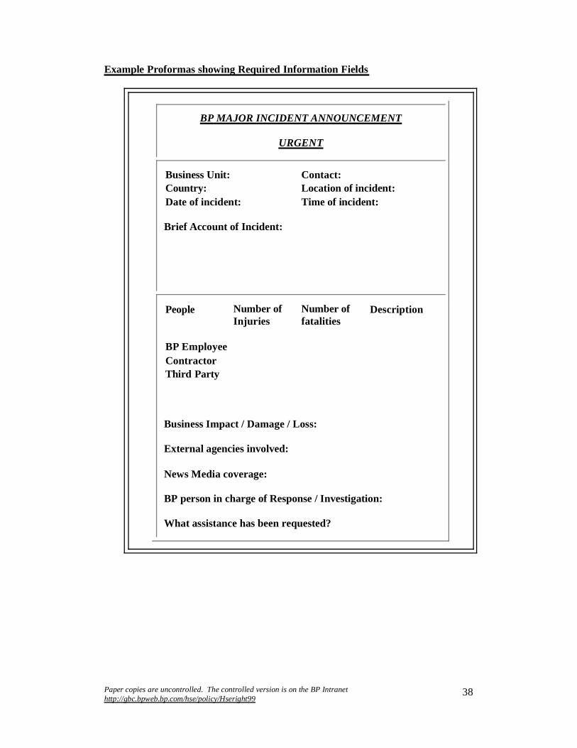
Paper copies are uncontrolled. The controlled version is on the BP Intranet http://gbc.bpweb.bp.com/hse/policy/Hseright99
38
Example Proformas showing Required Information Fields
BP MAJOR INCIDENT ANNOUNCEMENT
URGENT
Business Unit: Contact:Country: Location of incident:Date of incident: Time of incident:
Brief Account of Incident:
People Number of Injuries
Number of fatalities
Description
BP EmployeeContractorThird Party
Business Impact / Damage / Loss:
External agencies involved:
News Media coverage:
BP person in charge of Response / Investigation:
What assistance has been requested?

Paper copies are uncontrolled. The controlled version is on the BP Intranet http://gbc.bpweb.bp.com/hse/policy/Hseright99
39
BP HIGH POTENTIAL INCIDENT ANNOUNCEMENT
URGENT
Business Unit: Contact:
Country: Location of incident:
Date of incident: Time of incident:
Brief account of incident:
Potential Outcome:
Likely Cause:
Actions Taken:
BP person in charge:

Paper copies are uncontrolled. The controlled version is on the BP Intranet http://gbc.bpweb.bp.com/hse/policy/Hseright99
40
Key HSE Process 6
Incident Investigation Guidelines
It is essential to discover the root causes of incidents, so that :
effective preventive actions can be decided and implemented locally ‘Lessons Learned’ can be identified, implemented and shared with other
operations which have similar risks trends can be uncovered through valid statistical analysis
Detailed investigations should be carried out for all major incidents (injury or damage) and any minor incident or near-miss with a high potential of being a major one. Less serious incidents should be investigated with a degree of rigour appropriate to the potential for loss or injury. The principles employed are nonetheless the same
It is very unusual for an incident to have one single cause. Normally incidents result from a chain or combination of actions or errors, some going quite far back in time. This is why it is essential to have a systematic and thorough investigation, following a consistent methodology, so that the chain of causes can be tracked right back to its origins.
Investigation Procedure
All BP operations should have a detailed procedure to assist in this process which takes the investigation back through the chain of events that eventually resulted in the incident.
At each stage it is important to determine why these occurred and in which areas management control was deficient.
The linkages are tracked at each stage by asking the question ‘why’ to establish the factors that allowed the condition to occur.
At each stage there is seldom a single cause, and the investigator must search thoroughly to ensure that none are missed.
Procedure for Major Incident Investigations*
Following a major incident, an investigation should be initiated immediately by the Business Unit Manager along the following lines:
Step 1 - Appoint and fully brief team members, including appropriate technical experts, and a chairman with sufficient seniority and independence from the involved operation to reflect the seriousness of the incident.

Paper copies are uncontrolled. The controlled version is on the BP Intranet http://gbc.bpweb.bp.com/hse/policy/Hseright99
41
Step 2 - Issue terms of reference. These define the scope of the investigation and should include tracking the causation chain as well as other related factors, e.g. performance of emergency response and external services. Consider at what point legal advice may be required.
Step 3 - Specify timing of the report. It may be appropriate to issue an interim report within a few days of the incident to provide a factual account of events and some immediate recommendations for corrective action. It may also be necessary to alter the composition of the investigating team at this point if some particular expertise is found to be needed.
Step 4 - Issue the final report, which will be fully detailed with in-depth technical analysis and a fully considered set of short and long-term recommendations. Ideally the report should be issued within 30 days.
Once the report is available, Business Unit management should review the findings and recommendations and agree on their course of action. The final report should contain management responses to all recommendations with clear delegation of responsibilities for action. A timescale for review or completion is essential.
The Business Unit Leader will decide on the distribution of the full report, in particular which findings and ‘lessons learned’ are to be shared with others both inside and possibly outside BP.
* For incidents involving occupational fatalities, the Group Fatal Accident Investigation process will be activated.

Paper copies are uncontrolled. The controlled version is on the BP Intranet http://gbc.bpweb.bp.com/hse/policy/Hseright99
42
Key Process 7
HSE Performance Targets
BP's Commitment to HSE Performance sets clear aspirations: 'Our goals are simply stated - no accidents, no harm to people and no damage to the environment'
HSE targets are included in performance contracts at all levels within BP, for both individuals and groups, e.g. Business Units or Support Teams, as steps in the progression towards our goals and against which performance is assessed in the short to medium term.
In addition to serving as progress measures, there are two other important objectives in setting targets:
to encourage sound behaviours - by changing or reinforcing to demonstrate commitment - both internally and externally
Targets should be SMART i.e. Specific, Measurable, Achievable, Realistic and Timely. There is also scope for ‘stretch’ targets where the optimistic nature of the target represents a real challenge for the individual or the organization.
Targets can be expressed in terms of
outcomes - tangible results indicating improved performance, e.g. fewer injuries, spills, or near misses
Inputs - activities expected to cause or affect the desired outcomes, eg audits, training, or risk assessments completed
Both are important. Input targets tend to help drive behaviour and are therefore better used in individual performance contracts and at the facility level. Outcome targets help demonstrate commitment and work best with groups and at higher levels within the organization.
A combination of outcome and input targets is essential to focus effort and drive behaviour changes, especially when ‘stretch’ outcome targets are set.
Event based outcome targets for injuries or spills should be based on measures which are statistically significant over the timescale for achievement. Serious injuries are rare in many facilities; recordable injury and illness rate is therefore a more useful target measure when coupled with input measures such as task training completed or procedures reviewed
Group targets for emissions reductions similarly require input targets at the operational level such as reduced flaring or fugitive emission monitoring and control
Some Group level targets are publicised externally in the annual HSE Performance Report which can be found on the BP internet (www.bp.com). Others at Group and Business level remain part of the internal performance management system.

Paper copies are uncontrolled. The controlled version is on the BP Intranet http://gbc.bpweb.bp.com/hse/policy/Hseright99
43
Key HSE Process 8
HSE Reporting Requirements
HSE data collected by the Global Business Centre HSE Team are used to:
evaluate monthly, quarterly and annual performance trends for Executive and Group Vice Presidents and Business Stream Executive Committees
monitor performance against Group targets provide data for BP's Annual Report and Accounts and for the annual public HSE
report provide ad hoc reports for senior managers aggregated by Business stream or
clusters of Business Units
HSE data are submitted and retained in parallel with other Group systems for collecting financial and other performance data. Reporting units largely comprise Business and Support Units but other sub-groups are sometimes necessary.
Performance data are currently reported to the Group for all operations where BP has equity and is deemed to have operational responsibility and hence HSE responsibility
BP has expanded these reporting boundaries to encompass some operations where the Group has equity share, but not operational responsibility. Opportunities should therefore be taken to promote this concept with partners on a voluntary basis
Reporting units are designated by each Business Stream
Timely provision of HSE data is the responsibility of Business Unit Leaders, who nominate one or more contacts to liaise with the GBC HSE Team:
monthly and quarterly data are submitted the following month in line with the Group Financial Outlook (GFO) timetable
raw data are collected, not frequencies, to enable data aggregation
Some Business Units submit HSE data in their routine monthly reports to the Global Business Centre. These data should be consistent with the data submitted to the GBC HSE Team.
Data reporting requirements are generally similar for all Business Streams (see tabulation on page 44). Guidance on reporting major incidents, including fatalities, is found in Key Process 5. Safety and spills information is currently collected monthly, although use of Traction (BP’s online incident and action tracking system) allows reporting of such incidents. Environmental data is collected quarterly, 6-monthly or annually depending on the Business Stream requirements. Data collected throughout the reporting cycle is used externally to represent performance in our paper and web-based reports, and internally for performance comparison against targets. Data definitions are common across BP and are outlined in Key Process 10. The BP Environmental Reporting Guidelines are available on the internet at http://gbc.bpweb.bp.com/hse/performance/perform/protocol/Environ/index.htm.

Paper copies are uncontrolled. The controlled version is on the BP Intranet http://gbc.bpweb.bp.com/hse/policy/Hseright99
44
BPUpstream BP Downstream BP Chems BP G&P Other
Fatalities, injuries and illnesses (employees & contractors)
Fatalities (number)
Days Away From Work Cases (number)
Recordable Injuries & Illnesses (number)
Hours worked (number)
Transportation Incidents (employes & contractors)
Road accidents (number)
Distance driven, vehicle kms
Distribution incidents during transportation (number)
Distribution incidents at customer premises (number)
Spills 1 barrel (bbl) = 159 litres = 42 US gallons
Number of oil spills
Volu me of oil spilled (litres)
Volume of oil spilled but unrecovered (litres)
Spill to land or surface water
Spills which reach the environment (number)
Loss of containment(number)
Chemical releases (as defined, number)

Paper copies are uncontrolled. The controlled version is on the BP Intranet http://gbc.bpweb.bp.com/hse/policy/Hseright99
45
BPUpstream BP Downstream BP Chems BP G&P Other
Environmental data
Carbon dioxide emissions (tonnes)
Other emissions to air (tonnes)
Discharges to water (tonnes)
Waste (tonnes)
Notes:- reporting definitions for monthly reporting are set out in Key Process 1- all parameters reported as numbers unless otherwise indicated- injury frequencies will be calculated per 200,000 hours worked (as per OSHA definition)- road accident rates will be calculated per million vehicle kilometres driven
Paper copies are uncontrolled. The controlled version is on the BP Intranet http://gbc.bpweb.bp.com/hse/policy/Hseright99
46
Key HSE Process 9
Joint Ventures and other Operational Relationships
BP has varying forms of contractual relationships with third parties to work with themin areas such as joint ventures, operating agreements, tolling arrangements, licensing arrangements and franchises.
Where a Business Unit has any such relationship, the Business Unit Leader is responsible for ensuring that the third party:
has a Health, Safety and Environmental policy in place and can demonstrate compliance with that policy
can demonstrate compliance with legal obligations, and reports fatalities and serious incidents associated with the activity to BP
The Business Unit Leader will also require such additional HSE performance data as is necessary to provide assurance of compliance to the appropriate Group Vice President, in line with normal BP processes.
If it is determined that the third party is not in compliance with legal requirements, the Business Unit Leader will expect compliance within a specified time period. The Business Unit Leader will inform the Group Vice President when significant non-compliance is identified and keep the Group Vice President informed of actions being taken to achieve compliance.
Where BP’s relationship with a third party creates ownership in a separate operating entity such as a joint venture, the relevant performance data and assurance should be sought from the entity itself.
When BP ownership of an entity is greater than 40%, either through joint venture or direct ownership, or where there is significant risk to BP’s reputation, additional reporting requirements apply. Although this performance is not included in BP Group performance as described in Key Process 8, such entities should be held to the performance standards and reporting requirements applicable to wholly BP-owned or BP-operated entities. Specifically this entails provision of:
safety and incident data to meet BP Group definitions environmental data to meet the BP Group protocol
All such entities should be required to operate in a manner consistent with the BP Commitment to HSE Performance.

Paper copies are uncontrolled. The controlled version is on the BP Intranet http://gbc.bpweb.bp.com/hse/policy/Hseright99
47
Key HSE Process 10
HSE Reporting Definitions
Data requirements differ slightly by Business Stream, but data definitions are common across BP. The definitions are complex especially for environmental parameters. Reporting of injuries and illness requires good understanding of how to differentiate between
whether or not it is work-related, and whether it is an illness, an injury or a first aid treatment
Definitions for parameters reported monthly and other key indicators are included in this key process.
BP’s injury and illness definitions are the US Occupational Safety and Health Administration (OSHA) definitions as found in the document ‘Record Keeping for Occupational Injuries and Illnesses’ ('Blue Book') and in subsequent interpretation from OSHA. The definitions in this Key Process are based on the OSHA definitions. Additional guidance can be found in the BP document entitled 'Occupational Injury/Illness Group Reporting Guidelines'.
Detailed definitions supporting the calculation of environmental data are set out in the BP document entitled ‘Environmental Performance - Group Reporting Guidelines’.
The definitions associated with these Key Processes are used to ensure international comparability of data for internal BP reporting. Using the definitions may lead to differences between BP reports and locally reported HSE performance data using other guidelines, often required by legislation.
Definitions
Reporting Unit The name of Business Unit or Regional Services Unit or Site which is reporting data
Business or Business Stream Chemicals, Upstream, Downstream, or Other, (eg Solar)
Employee A person directly employed by a BP company.
Contractor A contractor is any non-BP person who is on BP premises under contract, for business purposes or anyone providing materials, personnel, or services that directly benefit BP and relate to a contract or subcontract. The contract may be with BP or another contractor who is working on behalf of BP.

Paper copies are uncontrolled. The controlled version is on the BP Intranet http://gbc.bpweb.bp.com/hse/policy/Hseright99
48
For group injury and illness reporting purposes, the following 'contractors' are excluded except in the event of a fatal accident when any contractor fatality must be reported:
· persons delivering goods, products or materials at a BP site
· someone engaged in the delivery of products by road in execution of a contract with a BP company that runs for less than one year (ie short term or spot contractors)
· a crew member of a vessel on short term or spot charter to a BP company (ie not on time charter).
· retail service station dealers and their staff at Company Owned Dealer Operated (CODO) sites.
· crew of a non-BP tanker loading or discharging crude oil or product for its own account at a marine terminal.
· injuries to workers in third party fabrication yards or toll-manufacturing sites will not be recorded at BP Group level. However, they should be monitored by Business Unit and/or Project management, and significant events reported through the Major Incident Announcement system.
Third Party Any person who is not an employee or contractor of BP as defined above
BP Premises A site operated by a BP company or a marine vessel owned or operated by a BP company.
BP Company A company wholly owned by the BP Group, or
a company or joint venture where BP has equity and is responsible for HSE. Normally this is where BP is considered to be the operator, (eg where BP has a management or technical service agreement).
Establishing a ‘work relationship’
The work relationship is established when the injury or illness results from an event or exposure in the work environment. The work environment primarily consists of:
· the employer’s premises, and

Paper copies are uncontrolled. The controlled version is on the BP Intranet http://gbc.bpweb.bp.com/hse/policy/Hseright99
49
· other locations where employees are engaged in work-relatedactivities or are present as a condition of their employment.
When an employee is on the employer’s premises (generallyexcluding parking lots) the work relationship is presumed; when off the premises the relationship must be established.
· travel on Company business should be considered work-related.
· a hotel or motel while being used on company business should be considered a 'home away from home' and evaluated as such.
· travel between home and work is not work-related.
· Injuries or illnesses that occur to employees or contractors while participating in voluntary activities (ie those that are provided or made possible by BP but in which participation is voluntary and for personal benefit, such as use of a fitness centre) shall not be included in the BP Group internal reporting. However, local recording, follow-up etc. is essential, as is compliance with all legal requirements.
RecordableFatality
(number)
An employee or contractor fatality is deemed recordable if the incident is found to be work-related or related to the wider activities of BP. Fatalities arising, for example, from suicide, inexplicable personal behaviour or natural causes would normally be excluded.All fatalities associated with BP, whether recordable or not, are reported within 24 hours through the Major Incident Announcement procedure.
Days Away From Work Case (DAFWC)(number)
A work-related injury or illness that causes the injured person to be away from work for at least one normal shift after the shift on which the injury occurred, because he/she is unfit to perform any duties. All DAFW Cases should be reported by the reporting unit at which they occurred.
RecordableInjury/Illness (RI) Case(number)
RI cases are all work-related deaths and illnesses, together with injuries that result in loss of consciousness, restriction of work or motion, transfer to another job, or require treatment beyond first aid.
RecordableInjury/IllnessFrequency (RIF)
RIF is expressed as the number of recordable injuries and illnesses per 200,000 hours worked.

Paper copies are uncontrolled. The controlled version is on the BP Intranet http://gbc.bpweb.bp.com/hse/policy/Hseright99
50
First Aid Cases A work related injury that requires one time treatment and subsequent observation (for example minor scratches, burns, cuts, splinters which do not ordinarily require medical care)and does not result in a DAFW or RI Case. Such treatment and observation are considered first aid even if provided by a physician or registered medical professional.
Hours Worked
(number)
Total hours worked within a reporting unit, including office staff, part-time employees, apprentices and trainees and personnel from other BP sites or centres working within the unit for more than one month.
Where a person is using Company property as a temporary home (eg on the Alaskan North Slope and offshore platforms) 12 hours should be taken as the working day. For ship operations at sea, a 24 hour working day should be taken.
OccupationalIllness and Industrial Diseases
(number)
An abnormal condition or disorder, other than one resulting from an occupational injury, caused by exposure to environmental factors associated with employment. It includes acute and chronic illnesses or diseases which may be caused by inhalation, absorption, ingestion or direct contact. Chronic conditions should be reported once, in the period during which the condition was first diagnosed.
See note at the end of this Key Process to differentiate between illness and injury.
Road Accidents
(number)
Accidents involving vehicles which occur on the road and result in damage or a work-related injury. Includes work-relatedoperation of vehicles by BP employees and product delivery vehicles or vehicles over 3.5 tonnes unladen operated by BP contractors.
· A zero-cost threshold is applied and reporting is irrespective of whether the accident was judged preventable or non-preventable.
· A BP operated vehicle is a delivery, or other vehicle driven by a BP employee for work related purposes, although the vehicle may be owned, hired or leased.
· A contractor operated delivery vehicle is either a company branded vehicle or a vehicle under a BP term contract (ie for more than one year) where the same driver is employed on a regular basis.
Distance Driven Total work related kilometres travelled by BP operated or
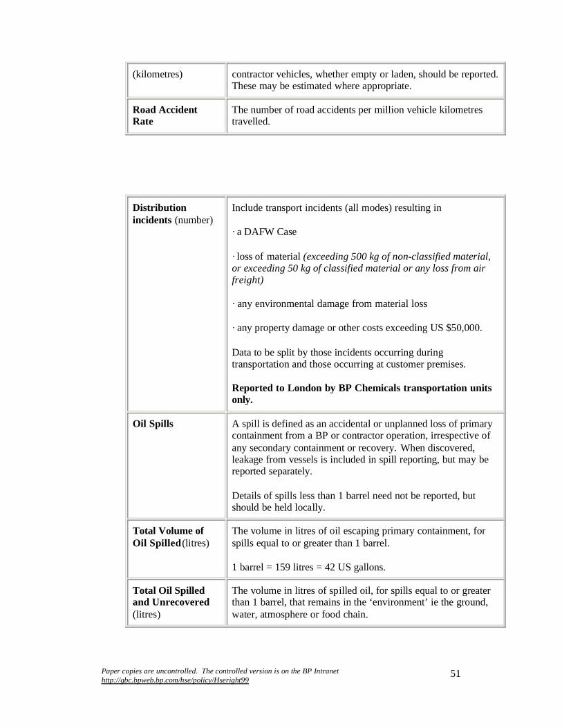
Paper copies are uncontrolled. The controlled version is on the BP Intranet http://gbc.bpweb.bp.com/hse/policy/Hseright99
51
(kilometres) contractor vehicles, whether empty or laden, should be reported.These may be estimated where appropriate.
Road Accident Rate
The number of road accidents per million vehicle kilometres travelled.
Distributionincidents (number)
Include transport incidents (all modes) resulting in
· a DAFW Case
· loss of material (exceeding 500 kg of non-classified material, or exceeding 50 kg of classified material or any loss from air freight)
· any environmental damage from material loss
· any property damage or other costs exceeding US $50,000.
Data to be split by those incidents occurring during transportation and those occurring at customer premises.
Reported to London by BP Chemicals transportation units only.
Oil Spills A spill is defined as an accidental or unplanned loss of primary containment from a BP or contractor operation, irrespective of any secondary containment or recovery. When discovered, leakage from vessels is included in spill reporting, but may be reported separately.
Details of spills less than 1 barrel need not be reported, but should be held locally.
Total Volume of Oil Spilled (litres)
The volume in litres of oil escaping primary containment, for spills equal to or greater than 1 barrel.
1 barrel = 159 litres = 42 US gallons.
Total Oil Spilled and Unrecovered(litres)
The volume in litres of spilled oil, for spills equal to or greater than 1 barrel, that remains in the ‘environment’ ie the ground, water, atmosphere or food chain.

Paper copies are uncontrolled. The controlled version is on the BP Intranet http://gbc.bpweb.bp.com/hse/policy/Hseright99
52
Oil Spills to Land or Water
If an oil spill reaches surface water (fresh, salt or brackish) it is defined as a spill to water, otherwise it is a spill to land.
Spills to snow or ice should be categorized according to their proximity to a shoreline - offshore is classified as 'to water' and onshore as 'to land'.
Spills which reach the environment
An oil spill greater than 1 barrel, where there is no secondary containment, or where any liquid breaches or leaks from secondary containment, to come into contact with the ground, snow, ice or water.
Chemical Releases (number)
The number of chemical releases that are reportable to local agencies under local regulations for BP Chemicals operations.
Loss of Containment(number)
Any unplanned event where hydrocarbons are released from primary containment and results in the need for action such as shutdown, evacuation or maintenance, to mitigate the effects of the loss of containment. Fugitive emissions should not be included.
Waste, Discharges and Emissions
Measurement and estimation protocols for wastes, discharges to water and emissions to air are published in ‘EnvironmentalPerformance - Group Reporting Guidelines’'.
Waste, discharges and emissions will be reported in metric tonnes. One tonne = 1000 kilograms, or 2200 pounds.
Difference Between Occupational Injury And Illness
The potential outcome of any ‘insult’ to the body, for example the consequences of a fall or exposure to a hazardous agent, is an adverse health effect. These are differentiated as either an injuryor illness/disease for analysis of causal factors. In a working environment, this is determined by the nature of the original event or exposure which caused the effect rather than the resulting condition of the affected employee.
Injuries are caused by instantaneous identifiable events in the working environment
Illnesses are caused by anything other than identifiable instantaneous events eg if repeated or prolonged exposure is involved the outcome is considered an illness. Additionally, a judgement needs to be made as to whether this exposure was work-related.

Paper copies are uncontrolled. The controlled version is on the BP Intranet http://gbc.bpweb.bp.com/hse/policy/Hseright99
53
Differentiation is not always straightforward and clear definitions are necessary. Some conditions could be classified as either an injury or an illness but not both. For example:
Hearing loss resulting from an explosion (an instantaneous event) is classified as an injury, whereas if it results from exposure to noise over a period of time it is classified as an illness
Contact with a hot surface or caustic chemical causing an instantaneous burn is an injury. Sunburn, frostbite and welding flash burns are normally classified as illnesses because they usually result from prolonged or repeated exposure
Tendonitis resulting from a one-time blow to the tendons of the hand is considered an injury, whereas repeated trauma or repetitive movement resulting in the same condition is considered an illness
Back cases should be classified as injuries because they are usually triggered by an instantaneous event. Classifying back cases as injuries is appropriate not only for cases resulting from identifiable events, but also for cases where the specific event cannot be pinpointed, since back cases are usually triggered by some specific movement (such as a slip, trip, fall, sharp twist, etc.). Such generalizations are necessary to keep record keeping determinations as simple and equitable as possible
Unlike injuries, illnesses may not be easily recognised and evaluation by trained medical personnel is desirable for confirmation both of diagnosis and attribution to occupational or non-occupational causation in accordance with the OSHA Guidelines. Once a work-related illness is diagnosed, managers are responsible for ensuring that they are reported.
Illnesses frequently involve factors such as multiple causation, historic exposures totally unrelated to the current working environment and may also not result in time away from work or require modified job duties. They may also recur or result in a chronic condition. Occupational illnesses are therefore reported only once - at the time of diagnosis or recognition. As a consequence, the calculation of meaningful severity or frequencies is more complicated than for injuries.

Paper copies are uncontrolled. The controlled version is on the BP Intranet http://gbc.bpweb.bp.com/hse/policy/Hseright99
54
Key HSE Process 11
Health Management
Safe and efficient operations depend on people. We must operate our facilities in a way that minimises health risks to employees, contractors and the community, and encourages our people to adopt a healthy lifestyle. This will enhance operations integrity, our reputation and productivity, and will establish a firm foundation for growth.
Health encompasses a 'spectrum' of states ranging from the extremes of premature death to optimum health. Good health benefits the individual and plays an integral part in delivering successful business performance by minimizing loss and maximising gain (Figure 1).
Health Risk Management - the 'Basics'**
(See Figure 2)
Effective health risk management encompasses four key activities:
Business Planning
Workplace, environmental and travel health hazards are identified, and risks are assessed:
for all new operations or modifications to plant or process before the acquisition of sites, leases, plant or materials before posting staff to remote, tropical or developing countries following changes in public and environmental health conditions.
Health Processes/Programmes

Paper copies are uncontrolled. The controlled version is on the BP Intranet http://gbc.bpweb.bp.com/hse/policy/Hseright99
55
These should be in place to cover:
medical management - the provision of medical support in the event of injury or illness, and to enable work in specified jobs or working environments
prevention - the control of workplace health risks to employees and contractors, the control of local public health risks to our employees and contractors, and control of environmental health risks to our neighbours, customers and the public from our operations and products
promotion - activities optimizing the health and well-being of our people
Health programmes are risk-based and their nature, scope and extent take into account the type and scale of the operation, the availability of suitable local health services, local hazards, legislation, standards and culture.
Health Measurement and Assessment
Procedures should be in place to:
report, investigate and document adverse health effects (illnesses) attributed to operations, processes, product or materials, and the working environment
audit, verify and provide assurance of performance against expectations and external benchmarks
Health records are maintained and data is periodically reviewed, to assess the effectiveness of hazard control measures and health management programmes.
Health Performance Improvement
A Process should be in place to periodically:
assess performance review health risks seek continuous improvement.

Paper copies are uncontrolled. The controlled version is on the BP Intranet http://gbc.bpweb.bp.com/hse/policy/Hseright99
56
Health Risk Management...the 'basics'

Paper copies are uncontrolled. The controlled version is on the BP Intranet http://gbc.bpweb.bp.com/hse/policy/Hseright99
57
Key HSE Process 12
HSE Toolbox
Implementation of each HSE Expectation requires one or more discrete management processes. Typical processes are set out in the BP ‘HSE Toolbox’ which is available on the Global Business Centre HSE Team Web Site.
The ‘HSE Toolbox’ lists the various management processes and references them back to the relevant HSE Expectation; it also outlines good practice features. It can be used as a tool for gap analysis, auditing and self regulation
The ‘HSE Toolbox’ output can also be reconfigured to match voluntary codes such as ISRS, REALM and ISO 14001 together with requirements such as US OSHA Process Safety Management regulations. This means that a single set of model management processes can meet the requirements for a wide range of code compliance and auditing purposes
The inventory of HSE management processes within the Toolbox is designed to evolve as good practice evolves and lessons are learned. Each process is assigned to a network or team for maintenance or updating
The 'HSE Toolbox' also contains several communications/sharing systems to enable a Network member to contribute good practice, ask questions on the Network and send Alerts on important HSE issues

Paper copies are uncontrolled. The controlled version is on the BP Intranet http://gbc.bpweb.bp.com/hse/policy/Hseright99
58
Glossary
ACCIDENT PREVENTION
Accident prevention includes Major Accidents which when relevant (eg in accordance with the SEVESO II directive) a Major Accident Prevention Policy (MAPP) will be drawn up to guarantee a high level of protection to man and the environment by appropriate means, structures and management systems.
ASSURANCE AUDITS
A process to objectively evaluate the business unit’s systemic management of the 13 elements of Getting HSE Right. The assessment consists of a review of policies, processes, programmes, documents and records coupled with selected field verification.
BENCHMARKING
A technique to compare and contrast the performance and practices of one business/facility with another in an attempt to share best practice.
BIODIVERSITY
The total variety of life on earth. It includes species, ecosystems and the whole of the natural world from the commonplace to the highly endangered. Loss of biodiversity has been linked with unsustainable development.
GVP
Group Vice President.
HAZOP
Hazard and Operability study, a hazard assessment technique used during the design stage of plant and equipment.
JOINT VENTURE
Any company that is not owned by BP but is in partnership with the Group via a contractual relationship to create a separate operating entity.
LEADER
Any person within the Group who has responsibility for others.
LIFE
The period of time from inception, through design, construction, operation and de-commissioning of plant and hardware, and the same period of time from the

Paper copies are uncontrolled. The controlled version is on the BP Intranet http://gbc.bpweb.bp.com/hse/policy/Hseright99
59
inception, through production, marketing, sale and eventual disposal of products, including their re-use or recycling.
NGO
Non-governmental organization.
OUTCOMES AND INPUTS
Information on HSE outcomes (lagging) and inputs (leading) is included in Key Process 2.
QRA
Quantified Risk Assessment.
SIMULTANEOUS OPERATIONS
Any instance where a work activity outside the normal scope of work for the particular location is occurring at the same time as normal operations. Examples include construction or demolition activities within or adjacent to operating plant, the use of a drilling rig on an existing installation etc.
STAKEHOLDERS
Anyone with an interest in the Group’s activities. Stakeholders include, for example, shareholders, employees, contractors, suppliers, customers, communities neighbouring our facilities and non-governmental organizations.
SUSTAINABLE DEVELOPMENT
As defined in Our Common Future, the 1992 Report of the Brundtland Commission, "Humanity has the ability to make development sustainable - to ensure that it meets the needs of the present without compromising the ability of future generations to meet their own needs".
Sustainable resources are those which are derived from supplies which can be or are replenished such that the resource level is maintained for future use by future generations.
TARGETS
Specific goals and objectives to be achieved. Targets may be set by leaders and managers throughout the Group, apply as defined to the appropriate Business Units, and are included in performance contracts at all levels within BP.
VOLUNTARY MANAGEMENT PROGRAMME

Paper copies are uncontrolled. The controlled version is on the BP Intranet http://gbc.bpweb.bp.com/hse/policy/Hseright99
60
Any management programme or system the Group or Business Unit subscribes to that is not a regulatory requirement. Examples include Responsible Care, ISO 9000/14001, EMAS, ISRS.
WORKFORCE
Our workforce is 'anyone who works for BP'. It includes employees, and contractorsand any other third party personnel when they work for the Group. Definitions of employees, contractors and third parties to be used for accident/incident reporting are included in the section on HSE Reporting Definitions.

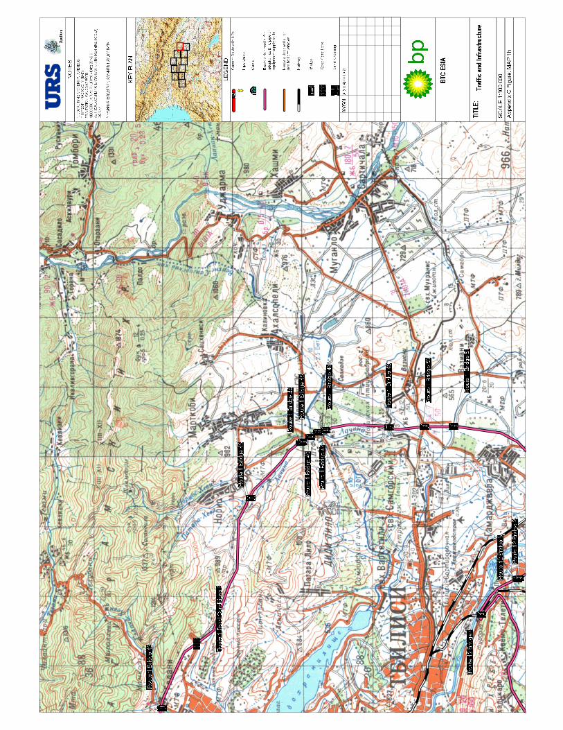


BTC PROJECT ESIAGEORGIA
FINAL ESIA
APPENDIX D I – SOCIAL BASELINENOVEMBER 2002
APPENDIX D SOCIAL BASELINE
ANNEX I COMMUNITYSURVEY SUMMARY
TABLE OF CONTENTS
Page No
Appendix D Annex 1 Community survey summary 1


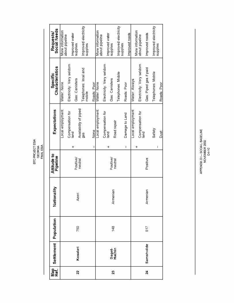
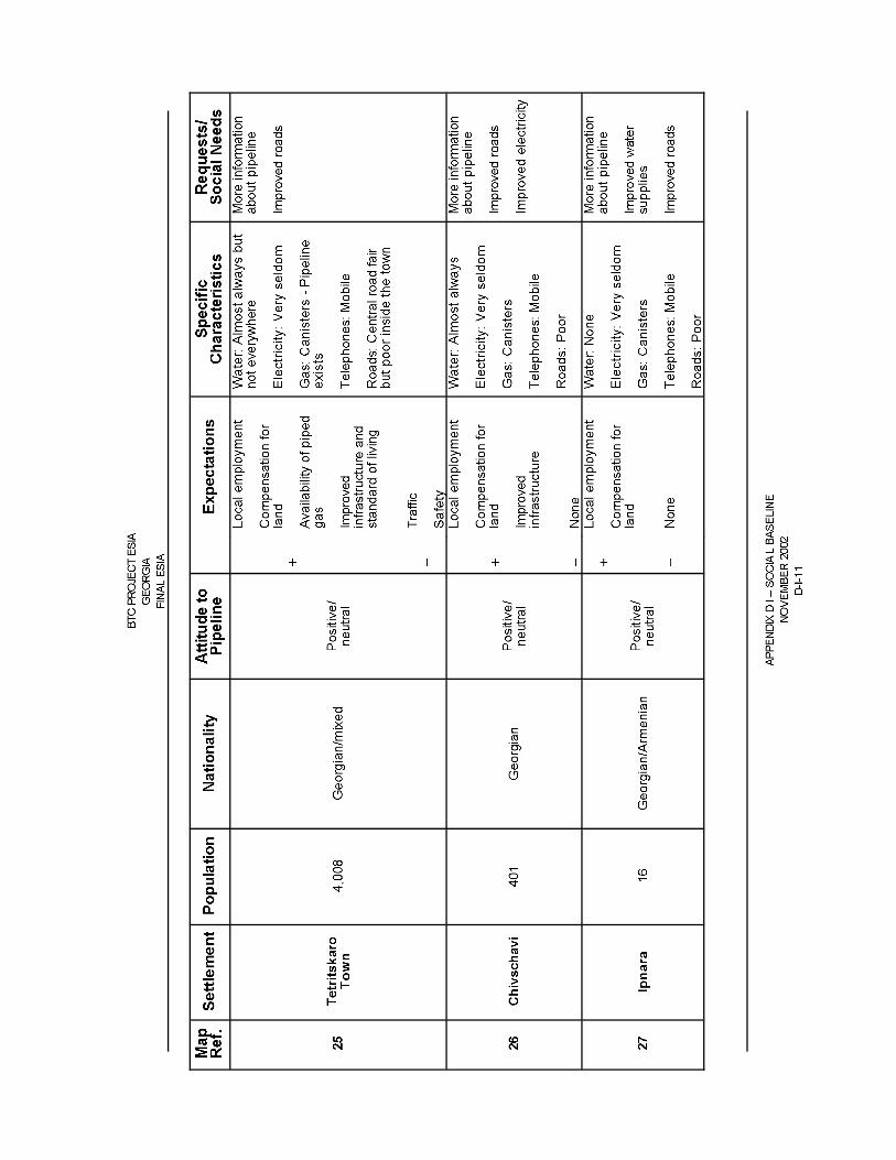


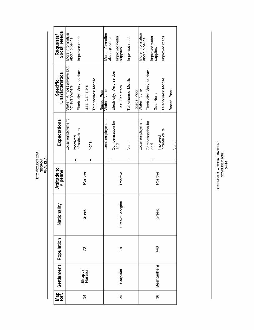


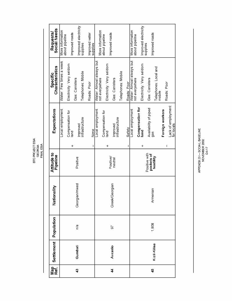
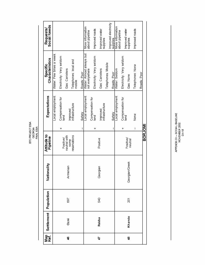


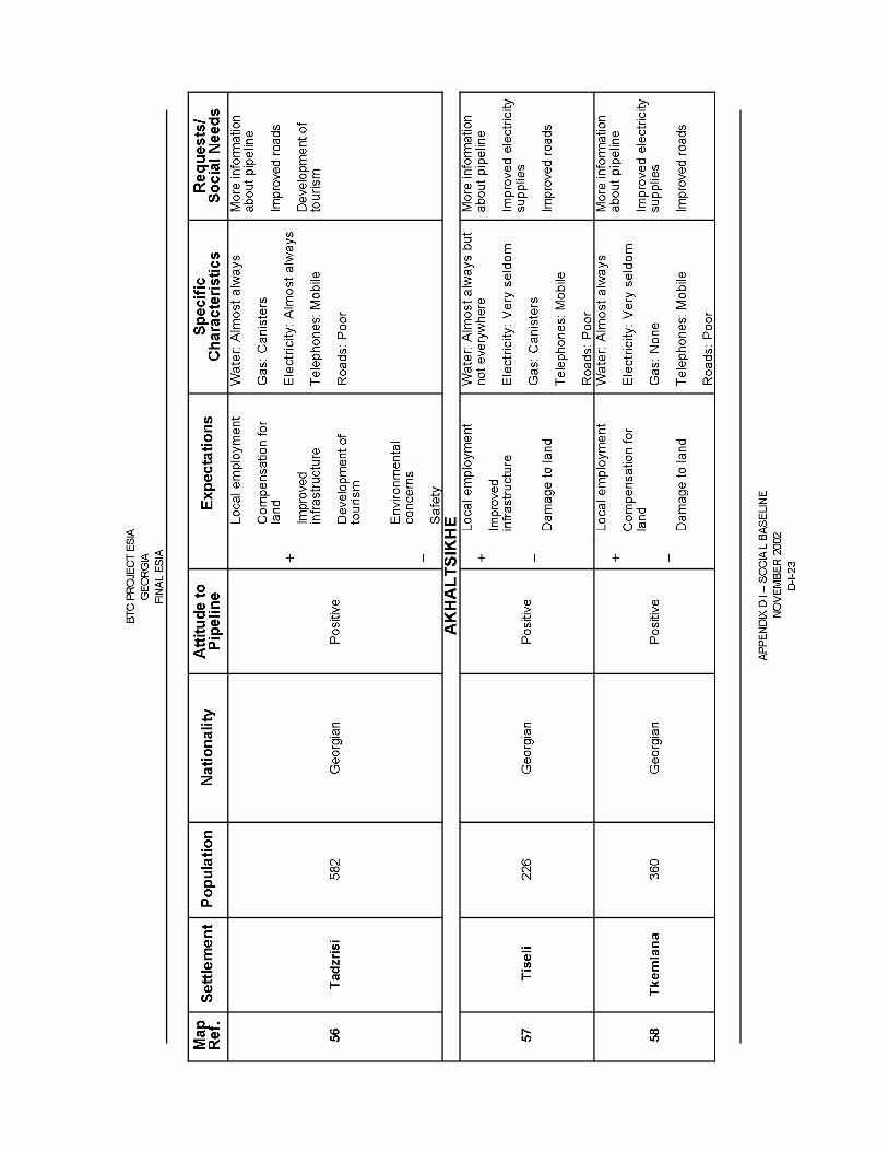

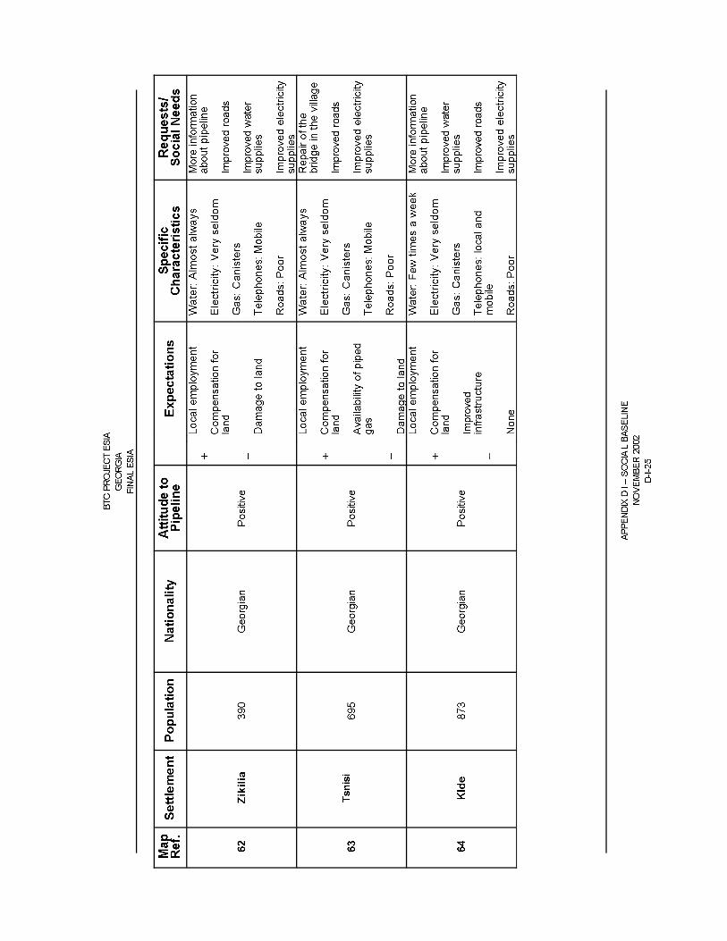
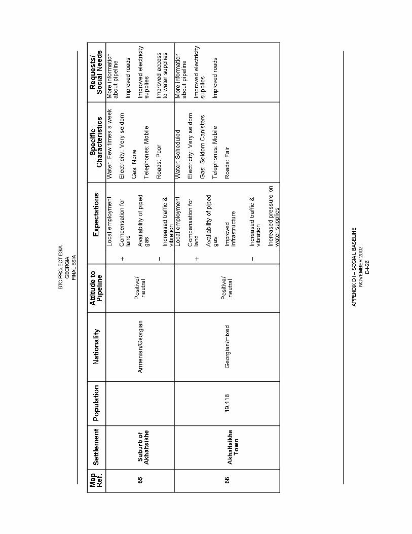


BTC PROJECT ESIAGEORGIA
FINAL ESIA
APPENDIX D II – SOCIAL BASELINENOVEMBER 2002
APPENDIX D SOCIAL BASELINE
ANNEX II TABLE OF SETTLEMENTS
TABLE OF CONTENTS
Appendix D Annex II Table of settlements
TABLES
Table 9.2 Table of settlements – with map references for Figure 9-2
FIGURES
Figure 9.2 Surveyed communities along the BTC pipelineFigure 9.2a Communities 1-6Figure 9.2b Communities 6-12Figure 9.2c Communities 12-22Figure 9.2d Communities 23-30Figure 9.2e Communities 31-38Figure 9.2f Communities 39-48Figure 9.2g Communities 49Figure 9.2h Communities 50-53Figure 9.2i Communities 54-63Figure 9.2j Communities 64-72

FILE NAME:8040\Fig 9.2 BTC Surveyed Communities 050402.WOR
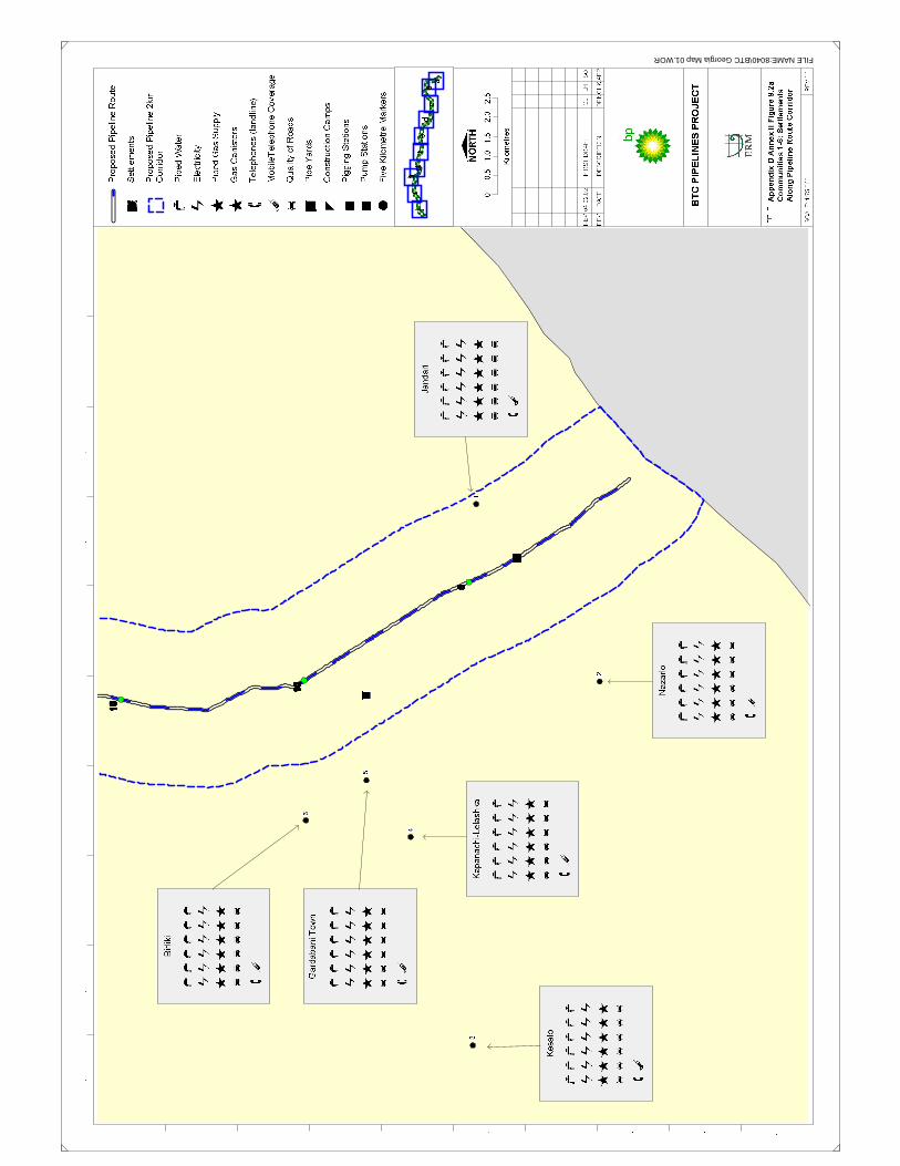
FILE NAME:8040\BTC Georgia Map 01.WOR

FILE NAME:8040\BTC Georgia Map 02.WOR

FILE NAME:8040\BTC Georgia Map 03.WOR

FILE NAME:8040\BTC Georgia Map 04.WOR

FILE NAME:8040\BTC Georgia Map 05.WOR

FILE NAME:8040\BTC Georgia Map 06.WOR

FILE NAME:8040\BTC Georgia Map 07.WOR

FILE NAME:8040\BTC Georgia Map 08.WOR
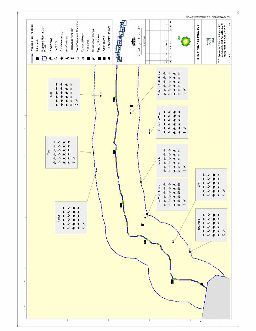
FILE NAME:8040\BTC Georgia Map 10.WOR

FILE NAME:8040\BTC Georgia Map 09.WOR


Calculated By: Neil Titley
Checked By: Ian James
Approved By: Ian James
Job Number: 47092-005
Client: BP
1
Exhaust gas flow= 34.65 kg/sec
Temperature of Discharge= 784 K
Moisture content of stack gas= 8.28 %
Oxygen content of stack gas= 14.37 %
Exhaust gas emission= 64 mg/Nm3 Reference Conditions= 15 %, Dry
No/ of Units 1
Need to Determine Pollutant Concentration at Stack Discharge Conditions (Cd)
Cd = Cs x (273/Td) x ((100-H2Od)/100) x ((20.9 - O2d) / (20.9 - O2s)) (D1 App B)
Where : Cs = Pollutant Concentration at Standard Conditions = 64 mg/m3
Td = Temperature of Discharge Gas = 784 K
H20d= Moisture content of discharge = 8.28 %
O2d= Oxygen content of discharge = 14.37 %
O2s= Oxygen content at reference conditions = 15 %
Thus: Pollutant Concentration at Stack Discharge (Cd) = 22.62 mg/m3
Calculate Discharge Volume Flow Rate at Stack Discharge (V)
V = Exhaust Gas Flow / Density of Gas at Discharge Temperature
Where : Exhaust Gas Flow = 34.65 Kg/sec
Density of Gas at Discharge Temperature = 0.450 Kg/m3
Thus : Volume Flow Rate at Stack Discharge (V) = 76.97 m3/s
Calculate Discharge Rate (D)D = (V x Cd)/1000 (D1 App B)Where: D = Discharge Rate at Discharge Conditions (g/s)
V = Discharge Volume Flow Rate at Discharge Conditions = 76.97 m3/s
Cd = Pollutant Concentration at Stack Discharge = 22.62 mg/m3
General IntroductionStack Height Determination for a Solar Mars 100 Gas Turbine - CO emissions
The following base conditions for each turbine have been used within the stack height calculations.
Calculate the Pollution Index (Pi)Pi =D / (Gd-Bc) (D1 eqn 1)
where: Pi = Pollution Index (m3/s) ED = Sum of Discharge rates for CHP units included within CHP scheme (Actual) (g/s) Gd = Guidance concentration of discharged pollutant (Actual Discharge conditions) (mg/m3) Bc = Background Concentration of discharged emission (mg/m3)

Calculated By: Neil Titley
Checked By: Ian James
Approved By: Ian James
Job Number: 47092-005
Client: BP
2
Thus: Discharge Rate = 1.74 g/s
Calculate Pollution Index (Pi)
Pi = (((D/(Gd-Bc))x1000) (D1 Eqn 1)
Where : D = COMBINED Discharge Rate of Pollutant FROM ALL STACKS IN STUDY 1.74 g/s = 1 x Discharge Rate (1 units operating, D1 4.2)Gd = Guidance Concentration of Pollutant AT STACK CONDITIONS 11.6 mg/m3
Bc = Background Concentration 0.002 mg/m3 (D1 Tab.2)
Pi = 150.14 m3/s
Determine Discharge Stack Height
Calculate Heat Release
Q = ((V(1-(283/Td))/2.9)x No. of Stacks) (D1 Eqn 3, D1 para. 6.4.2))
Where : V = Total Volume Flow at Discharge Conditions 76.97 m3/s
Td = Temperature of Discharge 784 K
Q = 17.0 MW
RULE : Q minimum = 0.03 MW (D1 5.2.1)Qactual > Qminimum, therefore proceed with Ub calculation
Calculate Uncorrected Stack Height for Buoyancy (Ub)
Ub = 10^a Pi^b (D1 Eqn 6)
Where for values of Q<1 MW: a = -1.11 - 0.19log10^Q (D1 Eqn 6)
b = 0.49 + 0.005log10^Q
Where for values of Q > 1 MW a= -0.84-0.1*exp(Q^0.31) (D1 Eqn 6)
b= 0.46+0.011.exp(Q^0.32)
Q>1Therefore : a = -1.95
b = 0.59
Therefore Ub = 0.22 m
RULE : Ub 1 m min (D1 5.3.3)200 m max
Q 0.03 kW min100 MW max
Pi 50 min10000000 max
Either Ub, Q or Pi do not comply with this rule, see D1
A value for Bc was obtained from Table 2 (D1 guidance notes), which details 'Typical Background Levels of Common Pollutants' bythe type of district. The area around the site was deemed to fall within the 'Partialld developed area' category.
Gd was obtained from UK Air Quality Standards, which sets 8 hour running mean air quality standards for CO .

Calculated By: Neil Titley
Checked By: Ian James
Approved By: Ian James
Job Number: 47092-005
Client: BP
3
Calculate Uncorrected Stack Height for Momentum (Um)
Firstly Determine Discharge Momentum (M):
M = (((283/Td)*V*w)x No. of Stacks) (Only When Discharges are from Combustion) (D1 Eqn 11, D1 para 6.4.2)
Td = Temperature of Discharge 784 KWhere :
w = Discharge Velocity Radius = 0.95 m w = V 27.15 m/s
V = Volume flow rate of discharge (at discharge temp.) 76.97 m3/s
M = 754.26 m4/s2
Calculate Um:
log10Um= x + (y*log10Pi+z)^0.5 (D1 Eqn 15)
Where : x = -3.7 + (log10 M)^0.9 (D1 Eqn 15)
y = 5.9 - 0.624log10 M
z = 4.24 - 9.7log10M + 1.47(log10M)^2 - 0.07(log10M)^3
Therefore : x = -1.111
y = 4.104
z = -13.168
log10Um = #NUM!Thus :
Um = 0.00
Minimum Value of Um= = 0.82M^0.32 (D1 Eqn 16) 6.83
Um<U minimum, therefore Um= 6.83
RULES : Um 1 m min (D1 5.3.3)200 m max
M 1 min2.1^10 max
Pi 50 min10^7 max
Either Um,M or Pi do not comply, see D1
SummaryUb = 0.22 m
Um = 6.83 m
Ub < Um, Therefore base Stack Height Calculation on Ub (D1 5.4.1) Therefore U = 0.22 m

Calculated By: Neil Titley
Checked By: Ian James
Approved By: Ian James
Job Number: 47092-005
Client: BP
4
Determine Final Stack Height For Multiple Buildings and Tall Buildings
C = Hm + (1 - Hm/Tm)[U + (Tm - U)(1 - A^-U/Hm)] (D1 Eqn 19)
C = Corrected Stack Height (m)
U = Uncorrected Discharge Stack Height = 0.22 m
A = Um/Ub (If there is no value of Ub or if Ub > Um, A = 1) = 31.42 m
H = Building Height = See Table Below
W = Building Width = See Table Below
K = Lesser of building height or building width = See Table Below
T = Height of disturbed flow over building = H + 1.5K = See Table Below
Tmax = Maximum T considering all relevant buildings = 27.5 m
Hmax = Maximum H considering all relevant buildings = 11.0 m
Consider all relevant Buildings (please refer to enclosed plan of site)
Building ID Building Height Building Width K TPump House 11 90 11 27.5
Hmax = 11.0 Tmax = 27.5
Therefore : C = Final corrected discharge stack height = 12.21 m

Calculated By: Neil Titley
Checked By: Ian James
Approved By: Ian James
Job Number: 47092-005
Client: BP
5
Exhaust gas flow= 34.65 kg/sec
Temperature of Discharge= 784 K
Moisture content of stack gas= 8.28 %
Oxygen content of stack gas= 14.37 %
Exhaust gas emission= 165 mg/Nm3 Reference Conditions= 15 %, Dry
No/ of Units 1
Need to Determine Pollutant Concentration at Stack Discharge Conditions (Cd)
Cd = Cs x (273/Td) x ((100-H2Od)/100) x ((20.9 - O2d) / (20.9 - O2s)) (D1 App B)
Where : Cs = Pollutant Concentration at Standard Conditions = 165 mg/m3
Td = Temperature of Discharge Gas = 784 K
H20d= Moisture content of discharge = 8.28 %
O2d= Oxygen content of discharge = 14.37 %
O2s= Oxygen content at reference conditions = 15 %
Thus: Pollutant Concentration at Stack Discharge (Cd) = 58.33 mg/m3
Calculate Discharge Volume Flow Rate at Stack Discharge (V)
V = Exhaust Gas Flow / Density of Gas at Discharge Temperature
Where : Exhaust Gas Flow = 34.65 Kg/sec
Density of Gas at Discharge Temperature = 0.450 Kg/m3
Thus : Volume Flow Rate at Stack Discharge (V) = 76.97 m3/s
Calculate Discharge Rate (D)D = (V x Cd)/1000 (D1 App B)Where: D = Discharge Rate at Discharge Conditions (g/s)
V = Discharge Volume Flow Rate at Discharge Conditions = 76.97 m3/s
Cd = Pollutant Concentration at Stack Discharge = 58.33 mg/m3
General IntroductionStack Height Determination for a Solar Mars 100 Gas Turbine - NOx emissions
The following base conditions for each turbine unit have been used within the stack height calculations.
Calculate the Pollution Index (Pi)Pi =D / (Gd-Bc) (D1 eqn 1)
where: Pi = Pollution Index (m3/s) ED = Sum of Discharge rates for CHP units included within CHP scheme (Actual) (g/s) Gd = Guidance concentration of discharged pollutant (Actual Discharge conditions) (mg/m3) Bc = Background Concentration of discharged emission (mg/m3)

Calculated By: Neil Titley
Checked By: Ian James
Approved By: Ian James
Job Number: 47092-005
Client: BP
6
Thus: Discharge Rate = 4.4893 g/s
Calculate Pollution Index (Pi)
Pi = (((D/(Gd-Bc))x1000) (D1 Eqn 1)
Where : D = COMBINED Discharge Rate of Pollutant FROM ALL STACKS IN STUDY 4.49 g/s = 1 x Discharge Rate (1 units operating, D1 4.2)Gd = Guidance Concentration of Pollutant AT STACK CONDITIONS 0.2 mg/m3 (85/205/EEC)
Bc = Background Concentration 0.002 mg/m3 (D1 Tab.2)
Pi = 22673.34 m3/s
Determine Discharge Stack Height
Calculate Heat Release
Q = ((V(1-(283/Td))/2.9)x No. of Stacks) (D1 Eqn 3, D1 para. 6.4.2))
Where : V = Total Volume Flow at Discharge Conditions 76.97 m3/s
Td = Temperature of Discharge 784 K
Q = 17.0 MW
RULE : Q minimum = 0.03 MW (D1 5.2.1)Qactual > Qminimum, therefore proceed with Ub calculation
Calculate Uncorrected Stack Height for Buoyancy (Ub)
Ub = 10^a Pi^b (D1 Eqn 6)
Where for values of Q<1 MW: a = -1.11 - 0.19log10^Q (D1 Eqn 6)
b = 0.49 + 0.005log10^Q
Where for values of Q > 1 MW a= -0.84-0.1*exp(Q^0.31) (D1 Eqn 6)
b= 0.46+0.011.exp(Q^0.32)
Q>1Therefore : a = -1.95
b = 0.59
Therefore Ub = 4.21 m
RULE : Ub 1 m min (D1 5.3.3)200 m max
Q 0.03 kW min100 MW max
Pi 50 min10000000 max
A value for Bc was obtained from Table 2 (D1 guidance notes), which details 'Typical Background Levels of Common Pollutants' bythe type of district. The area around the site was deemed to fall within the 'Partialld developed area' category.
Gd was obtained from the 98th percentile calculated from the mean values per hour, or per period less than an hour, recorded throughout the year (85/205/EEC)

Calculated By: Neil Titley
Checked By: Ian James
Approved By: Ian James
Job Number: 47092-005
Client: BP
7
Ub, Q and Pi all comply with this rule
Calculate Uncorrected Stack Height for Momentum (Um)
Firstly Determine Discharge Momentum (M):
M = (((283/Td)*V*w)x No. of Stacks) (Only When Discharges are from Combustion) (D1 Eqn 11, D1 para 6.4.2)
Td = Temperature of Discharge 784 KWhere :
w = Discharge Velocity Radius = 0.95 m w = V 27.15 m/s
V = Volume flow rate of discharge (at discharge temp.) 76.97 m3/s
M = 754.26 m4/s2
Calculate Um:
log10Um= x + (y*log10Pi+z)^0.5 (D1 Eqn 15)
Where : x = -3.7 + (log10 M)^0.9 (D1 Eqn 15)
y = 5.9 - 0.624log10 M
z = 4.24 - 9.7log10M + 1.47(log10M)^2 - 0.07(log10M)^3
Therefore : x = -1.111
y = 4.104
z = -13.168
log10Um = 1.059Thus :
Um = 11.45
Minimum Value of Um= = 0.82M^0.32 (D1 Eqn 16) 6.83
Um>U minimumn, therefore Um= 11.45
RULES : Um 1 m min (D1 5.3.3)200 m max
M 1 min2.1^10 max
Pi 50 min10^7 max
Um, M, Pi all comply to these rules
SummaryUb = 4.21 m
Um = 11.45 m
Ub < Um, Therefore base Stack Height Calculation on Ub (D1 5.4.1) Therefore U = 4.21 m
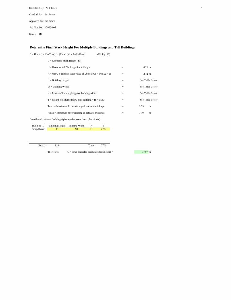
Calculated By: Neil Titley
Checked By: Ian James
Approved By: Ian James
Job Number: 47092-005
Client: BP
8
Determine Final Stack Height For Multiple Buildings and Tall Buildings
C = Hm + (1 - Hm/Tm)[U + (Tm - U)(1 - A^-U/Hm)] (D1 Eqn 19)
C = Corrected Stack Height (m)
U = Uncorrected Discharge Stack Height = 4.21 m
A = Um/Ub (If there is no value of Ub or if Ub > Um, A = 1) = 2.72 m
H = Building Height = See Table Below
W = Building Width = See Table Below
K = Lesser of building height or building width = See Table Below
T = Height of disturbed flow over building = H + 1.5K = See Table Below
Tmax = Maximum T considering all relevant buildings = 27.5 m
Hmax = Maximum H considering all relevant buildings = 11.0 m
Consider all relevant Buildings (please refer to enclosed plan of site)
Building ID Building Height Building Width K TPump House 11 90 11 27.5
Hmax = 11.0 Tmax = 27.5
Therefore : C = Final corrected discharge stack height = 17.97 m

Calculated By: Neil Titley
Checked By: Ian James
Approved By: Ian James
Job Number: 47092-005
Client: BP
9
Exhaust gas flow= 34.65 kg/sec
Temperature of Discharge= 784 K
Moisture content of stack gas= 8.28 %
Oxygen content of stack gas= 14.37 %
Exhaust gas emission= 91 mg/Nm3 Reference Conditions= 15 %, Dry
No/ of Units 1
Need to Determine Pollutant Concentration at Stack Discharge Conditions (Cd)
Cd = Cs x (273/Td) x ((100-H2Od)/100) x ((20.9 - O2d) / (20.9 - O2s)) (D1 App B)
Where : Cs = Pollutant Concentration at Standard Conditions = 91 mg/m3
Td = Temperature of Discharge Gas = 784 K
H20d= Moisture content of discharge = 8.28 %
O2d= Oxygen content of discharge = 14.37 %
O2s= Oxygen content at reference conditions = 15 %
Thus: Pollutant Concentration at Stack Discharge (Cd) = 32.17 mg/m3
Calculate Discharge Volume Flow Rate at Stack Discharge (V)
V = Exhaust Gas Flow / Density of Gas at Discharge Temperature
Where : Exhaust Gas Flow = 34.65 Kg/sec
Density of Gas at Discharge Temperature = 0.450 Kg/m3
Thus : Volume Flow Rate at Stack Discharge (V) = 76.97 m3/s
Calculate Discharge Rate (D)D = (V x Cd)/1000 (D1 App B)Where: D = Discharge Rate at Discharge Conditions (g/s)
V = Discharge Volume Flow Rate at Discharge Conditions = 76.97 m3/s
General IntroductionStack Height Determination for a Solar Mars 100 Gas Turbine - SOx emissions
The following base conditions for each turbine unit have been used within the stack height calculations.
Calculate the Pollution Index (Pi)Pi =D / (Gd-Bc) (D1 eqn 1)
where: Pi = Pollution Index (m3/s) ED = Sum of Discharge rates for CHP units included within CHP scheme (Actual) (g/s) Gd = Guidance concentration of discharged pollutant (Actual Discharge conditions) (mg/m3) Bc = Background Concentration of discharged emission (mg/m3)

Calculated By: Neil Titley
Checked By: Ian James
Approved By: Ian James
Job Number: 47092-005
Client: BP
10
Cd = Pollutant Concentration at Stack Discharge = 32.17 mg/m3
Thus: Discharge Rate = 2.48 g/s
Calculate Pollution Index (Pi)
Pi = (((D/(Gd-Bc))x1000) (D1 Eqn 1)
Where : D = COMBINED Discharge Rate of Pollutant FROM ALL STACKS IN STUDY 2.48 g/s = 1 x Discharge Rate (1 units operating, D1 4.2)Gd = Guidance Concentration of Pollutant AT STACK CONDITIONS 0.35 mg/m3 (80/779/EEC)
(89/427/EEC)Bc = Background Concentration 0.002 mg/m3 (D1 Tab.2)
Pi = 7114.74 m3/s
Determine Discharge Stack Height
Calculate Heat Release
Q = ((V(1-(283/Td))/2.9)x No. of Stacks) (D1 Eqn 3, D1 para. 6.4.2))
Where : V = Total Volume Flow at Discharge Conditions 76.97 m3/s
Td = Temperature of Discharge 784 K
Q = 17.0 MW
RULE : Q minimum = 0.03 MW (D1 5.2.1)Qactual > Qminimum, therefore proceed with Ub calculation
Calculate Uncorrected Stack Height for Buoyancy (Ub)
Ub = 10^a Pi^b (D1 Eqn 6)
Where for values of Q<1 MW: a = -1.11 - 0.19log10^Q (D1 Eqn 6)
b = 0.49 + 0.005log10^Q
Where for values of Q > 1 MW a= -0.84-0.1*exp(Q^0.31) (D1 Eqn 6)
b= 0.46+0.011.exp(Q^0.32)
Q>1Therefore : a = -1.95
b = 0.59
Therefore Ub = 2.12 m
RULE : Ub 1 m min (D1 5.3.3)200 m max
Q 0.03 kW min
A value for Bc was obtained from Table 2 (D1 guidance notes), which details 'Typical Background Levels of Common Pollutants' bythe type of district. The area around the site was deemed to fall within the 'Partialld developed area' category.
Gd based upon EU standards where the 98th percentile of daily mean smoke value is 150-350 ug/m3 (80/779/EEC) amended by (89/427/EEC).

Calculated By: Neil Titley
Checked By: Ian James
Approved By: Ian James
Job Number: 47092-005
Client: BP
11
100 MW maxPi 50 min
10000000 maxUb, Q and Pi all comply with this rule
Calculate Uncorrected Stack Height for Momentum (Um)
Firstly Determine Discharge Momentum (M):
M = (((283/Td)*V*w)x No. of Stacks) (Only When Discharges are from Combustion) (D1 Eqn 11, D1 para 6.4.2)
Td = Temperature of Discharge 784 KWhere :
w = Discharge Velocity Radius = 0.95 m w = V 27.15 m/s
V = Volume flow rate of discharge (at discharge temp.) 76.97 m3/s
M = 754.26 m4/s2
Calculate Um:
log10Um= x + (y*log10Pi+z)^0.5 (D1 Eqn 15)
Where : x = -3.7 + (log10 M)^0.9 (D1 Eqn 15)
y = 5.9 - 0.624log10 M
z = 4.24 - 9.7log10M + 1.47(log10M)^2 - 0.07(log10M)^3
Therefore : x = -1.111
y = 4.104
z = -13.168
log10Um = 0.515Thus :
Um = 3.27
Minimum Value of Um= = 0.82M^0.32 (D1 Eqn 16) 6.83
Um<U minimum, therefore Um= 6.83
RULES : Um 1 m min (D1 5.3.3)200 m max
M 1 min2.1^10 max
Pi 50 min10^7 max
Um, M, Pi all comply to these rules
SummaryUb = 2.12 m
Um = 6.83 m

Calculated By: Neil Titley
Checked By: Ian James
Approved By: Ian James
Job Number: 47092-005
Client: BP
12
Ub < Um, Therefore base Stack Height Calculation on Ub (D1 5.4.1) Therefore U = 2.12 m
Determine Final Stack Height For Multiple Buildings and Tall Buildings
C = Hm + (1 - Hm/Tm)[U + (Tm - U)(1 - A^-U/Hm)] (D1 Eqn 19)
C = Corrected Stack Height (m)
U = Uncorrected Discharge Stack Height = 2.12 m
A = Um/Ub (If there is no value of Ub or if Ub > Um, A = 1) = 3.22 m
H = Building Height = See Table Below
W = Building Width = See Table Below
K = Lesser of building height or building width = See Table Below
T = Height of disturbed flow over building = H + 1.5K = See Table Below
Tmax = Maximum T considering all relevant buildings = 27.5 m
Hmax = Maximum H considering all relevant buildings = 11.0 m
Consider all relevant Buildings (please refer to enclosed plan of site)
Building ID Building Height Building Width K TPump House 11 90 11 27.5
Hmax = 11.0 Tmax = 27.5
Therefore : C = Final corrected discharge stack height = 15.35 m

Calculated By: Neil Titley
Checked By: Ian James
Approved By: Ian James
Job Number: 47092-005
Client: BP
13
Exhaust gas flow= 34.65 kg/sec
Temperature of Discharge= 784 K
Moisture content of stack gas= 8.28 %
Oxygen content of stack gas= 14.37 %
Exhaust gas emission= 18 mg/Nm3 Reference Conditions= 15 %, Dry
No/ of Units 1
Need to Determine Pollutant Concentration at Stack Discharge Conditions (Cd)
Cd = Cs x (273/Td) x ((100-H2Od)/100) x ((20.9 - O2d) / (20.9 - O2s)) (D1 App B)
Where : Cs = Pollutant Concentration at Standard Conditions = 18 mg/m3
Td = Temperature of Discharge Gas = 784 K
H20d= Moisture content of discharge = 8.28 %
O2d= Oxygen content of discharge = 14.37 %
O2s= Oxygen content at reference conditions = 15 %
Thus: Pollutant Concentration at Stack Discharge (Cd) = 6.36 mg/m3
Calculate Discharge Volume Flow Rate at Stack Discharge (V)
V = Exhaust Gas Flow / Density of Gas at Discharge Temperature
Where : Exhaust Gas Flow = 34.65 Kg/sec
Density of Gas at Discharge Temperature = 0.450 Kg/m3
Thus : Volume Flow Rate at Stack Discharge (V) = 76.97 m3/s
Calculate Discharge Rate (D)D = (V x Cd)/1000 (D1 App B)Where: D = Discharge Rate at Discharge Conditions (g/s)
V = Discharge Volume Flow Rate at Discharge Conditions = 76.97 m3/s
General IntroductionStack Height Determination for a Solar Mars 100 Gas Turbine - PM emissions
The following base conditions for each turbine unit have been used within the stack height calculations.
Calculate the Pollution Index (Pi)Pi =D / (Gd-Bc) (D1 eqn 1)
where: Pi = Pollution Index (m3/s) ED = Sum of Discharge rates for CHP units included within CHP scheme (Actual) (g/s) Gd = Guidance concentration of discharged pollutant (Actual Discharge conditions) (mg/m3) Bc = Background Concentration of discharged emission (mg/m3)

Calculated By: Neil Titley
Checked By: Ian James
Approved By: Ian James
Job Number: 47092-005
Client: BP
14
Cd = Pollutant Concentration at Stack Discharge = 6.36 mg/m3
Thus: Discharge Rate = 0.49 g/s
Calculate Pollution Index (Pi)
Pi = (((D/(Gd-Bc))x1000) (D1 Eqn 1)
Where : D = COMBINED Discharge Rate of Pollutant FROM ALL STACKS IN STUDY 0.49 g/s = 1 x Discharge Rate (1 units operating, D1 4.2)Gd = Guidance Concentration of Pollutant AT STACK CONDITIONS 0.25 mg/m3 (80/779/EEC)
Bc = Background Concentration 0.002 mg/m3 (D1 Tab.2)
Pi = 1974.77 m3/s
Determine Discharge Stack Height
Calculate Heat Release
Q = ((V(1-(283/Td))/2.9)x No. of Stacks) (D1 Eqn 3, D1 para. 6.4.2))
Where : V = Total Volume Flow at Discharge Conditions 76.97 m3/s
Td = Temperature of Discharge 784 K
Q = 17.0 MW
RULE : Q minimum = 0.03 MW (D1 5.2.1)Qactual > Qminimum, therefore proceed with Ub calculation
Calculate Uncorrected Stack Height for Buoyancy (Ub)
Ub = 10^a Pi^b (D1 Eqn 6)
Where for values of Q<1 MW: a = -1.11 - 0.19log10^Q (D1 Eqn 6)
b = 0.49 + 0.005log10^Q
Where for values of Q > 1 MW a= -0.84-0.1*exp(Q^0.31) (D1 Eqn 6)
b= 0.46+0.011.exp(Q^0.32)
Q>1Therefore : a = -1.95
b = 0.59
Therefore Ub = 1.00 m
RULE : Ub 1 m min (D1 5.3.3)200 m max
Q 0.03 kW min
A value for Bc was obtained from Table 2 (D1 guidance notes), which details 'Typical Background Levels of Common Pollutants' bythe type of district. The area around the site was deemed to fall within the 'Partialld developed area' category.
Gd based upon EU standards for the 98th percentile of all daily mean values taken throughout the year (80/779/EEC).

Calculated By: Neil Titley
Checked By: Ian James
Approved By: Ian James
Job Number: 47092-005
Client: BP
15
100 MW maxPi 50 min
10000000 maxEither Ub, Q or Pi do not comply with this rule, see D1
Calculate Uncorrected Stack Height for Momentum (Um)
Firstly Determine Discharge Momentum (M):
M = (((283/Td)*V*w)x No. of Stacks) (Only When Discharges are from Combustion) (D1 Eqn 11, D1 para 6.4.2)
Td = Temperature of Discharge 784 KWhere :
w = Discharge Velocity Radius = 0.95 m w = V 27.15 m/s
V = Volume flow rate of discharge (at discharge temp.) 76.97 m3/s
M = 754.26 m4/s2
Calculate Um:
log10Um= x + (y*log10Pi+z)^0.5 (D1 Eqn 15)
Where : x = -3.7 + (log10 M)^0.9 (D1 Eqn 15)
y = 5.9 - 0.624log10 M
z = 4.24 - 9.7log10M + 1.47(log10M)^2 - 0.07(log10M)^3
Therefore : x = -1.111
y = 4.104
z = -13.168
log10Um = -0.513Thus :
Um = 0.31
Minimum Value of Um= = 0.82M^0.32 (D1 Eqn 16) 6.83
Um<U minimum, therefore Um= 6.83
RULES : Um 1 m min (D1 5.3.3)200 m max
M 1 min2.1^10 max
Pi 50 min10^7 max
Either Um,M or Pi do not comply, see D1
SummaryUb = 1.00 m
Um = 6.83 m

Calculated By: Neil Titley
Checked By: Ian James
Approved By: Ian James
Job Number: 47092-005
Client: BP
16
Ub < Um, Therefore base Stack Height Calculation on Ub (D1 5.4.1) Therefore U = 1.00 m
Determine Final Stack Height For Multiple Buildings and Tall Buildings
C = Hm + (1 - Hm/Tm)[U + (Tm - U)(1 - A^-U/Hm)] (D1 Eqn 19)
C = Corrected Stack Height (m)
U = Uncorrected Discharge Stack Height = 1.00 m
A = Um/Ub (If there is no value of Ub or if Ub > Um, A = 1) = 6.86 m
H = Building Height = See Table Below
W = Building Width = See Table Below
K = Lesser of building height or building width = See Table Below
T = Height of disturbed flow over building = H + 1.5K = See Table Below
Tmax = Maximum T considering all relevant buildings = 27.5 m
Hmax = Maximum H considering all relevant buildings = 11.0 m
Consider all relevant Buildings (please refer to enclosed plan of site)
Building ID Building Height Building Width K TPump House 11 90 11 27.5
Hmax = 11.0 Tmax = 27.5
Therefore : C = Final corrected discharge stack height = 14.14 m
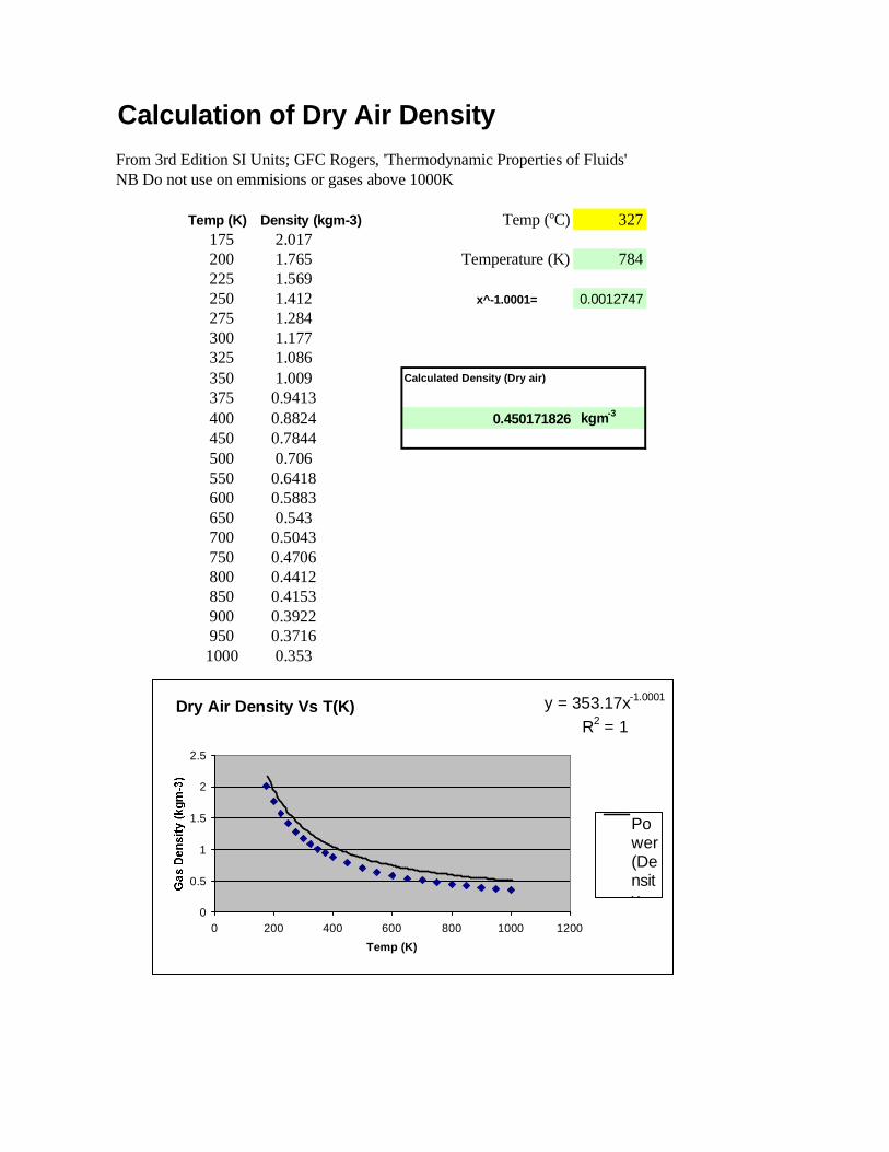
Calculation of Dry Air DensityFrom 3rd Edition SI Units; GFC Rogers, 'Thermodynamic Properties of Fluids'NB Do not use on emmisions or gases above 1000K
Temp (K) Density (kgm-3) Temp (oC) 327175 2.017200 1.765 Temperature (K) 784225 1.569250 1.412 x^-1.0001= 0.0012747275 1.284300 1.177325 1.086350 1.009 Calculated Density (Dry air)
375 0.9413400 0.8824 0.450171826 kgm-3
450 0.7844500 0.706550 0.6418600 0.5883650 0.543700 0.5043750 0.4706800 0.4412850 0.4153900 0.3922950 0.37161000 0.353
Dry Air Density Vs T(K) y = 353.17x-1.0001
R2 = 1
0
0.5
1
1.5
2
2.5
0 200 400 600 800 1000 1200Temp (K)
Power(Density

BTC PROJECT ESIAGEORGIA
FINAL ES IA
APPENDIX E III CULTURAL HERITAGE MANAGEMENT PLANNOVEMBER 2002
APPENDIX E ENVIRONM ENTAL IMPACTS AND MITIGATION
ANNEX III CULTURAL HERITAGE MANAGEMENT PLAN
FOR BP BTC AND SCP PROJECTS
TABLE OF CONTENTSPage No
1 Introduction 11.1 Background 11.2 Heritage Resources in Project Area 2
2 Project Cultural Heritage Sites Database 23 Phase I Activities (Pre-construction-Completed) 3
3.1 Overview 33.2 Archaeological Sites 33.3 Historic Monuments 33.4 Phase I Summary 3
4 Phase II Activitie s (pre-construction) 44.1 Overview 44.2 Archaeological Sites 44.3 Historic Monuments 5
5 Phase III Activities (pre-construction) 55.1 Overview 55.2 Archaeological Sites 55.3 Historic Monuments 6
6 Phase IV Activities (During Construction) 66.1 Overview 66.2 Archaeological Sites 66.3 Monuments 76.4 Chance Finds Reporting and Action Protocols for the Phase IV Archaeological Monitoring 7

BTC PROJECT ESIAGEORGIA
FINAL ES IA
APPENDIX E III CULTURAL HERITAGE MANAGEMENT PLANNOVEMBER 2002
TABLES
Table 1 Summary of BP cultural heritage management plan 8Table 2 Periods of Georgian prehistory and history 9Table 3 Archaeological sites identified for Phase II field investigation 10
FIGURES
Figure 1 12
ATTACHMENTS
Attachment I Scope of Work for Phase II ArchaeologyAttachment II Scope of Work for Phase I Monuments Investigation

BTC PROJECT ESIAGEORGIA
FINAL ES IA
APPENDIX E III CULTURAL HERITAGE MANAGEMENT PLANNOVEMBER 2002
E- III-1
Appendix E Annex III
CULTURAL HERITAGE MANAGEMENT PLANFOR BP BTC AND SCP PROJECTS
1 INTRODUCTION
1.1 BACKGROUNDThe project has developed a Cultural Heritage Management Plan (CHMP) to avoid and/or minimise project impacts to archaeological and historic monument sites as a result of the construction of the pipeline facilities and associated features such as access roads. These two categories of historic resources, also referred to by partially overlapping terms culturalproperties, cultural resources, or physical cultural resources, are defined as follows:
Archaeological sites are primarily buried cultural remains (historic or prehistoric) Monuments are above-ground historic or prehistoric structures in variable states of
preservation along with associated landscapes
British Petroleum (BP) developed the plan and its supporting information as part of theEnvironmental and Social Impact Assessment (ESIA) process and in line with applicable Georgian law and the environmental standards of multilateral lending agencies. Specifically, the CHMP complies with International Finance Corporation (IFC) cultural properties protection standards identified by IFC Operational Policy Note OPN 11.03 (1986) entitled “Cultural Property”. It is the general corporate policy of BP to advance the objectives of cultural heritage protection in all of its projects, and to comply with all specific applicable national andinternational heritage requirements. BP contractors are required to conform to BP policy.
BP developed the Georgian project CHMP in consultation with the Centre for Archaeological Studies (CAS), the Georgian government agency currently charged with archaeologicalprotection. For this project CAS is also charged with coordinating monuments protection, which is normally the task of the Georgian Department Monuments Protection. CAS and the Georgian Monuments Protection Department have agreed to the to the CHMP and have also agreed to the Phase I and Phase II scopes of work for archaeological and monuments protection which areattached, in part, to this report. Subsequent scopes of work required under the plan will be developed in turn by a similar process of consultation with appropriate authorities.Implementation of the scopes of work has included the direct involvement of CAS.
Invitation to Tender (ITT) documentation for prospective project construction contractors has included guidance on the scope and importance of known and potential heritage resources in the project area, and the heritage protection requirements with which BP contractors must comply. BP project heritage planning includes anticipated budget and schedule impacts of heritage issues to be addressed prior to and during the construction process.
BP has organized CHMP activities in a phased manner in which findings from earlier phases provide a basis for specific actions to be taken in later phases. BP is employing contractor research teams consisting of international and Georgian archaeologists, monuments specialists,
BTC PROJECT ESIAGEORGIA
FINAL ES IA
APPENDIX E III CULTURAL HERITAGE MANAGEMENT PLANNOVEMBER 2002
E- III-2
and cultural resource management specia lists to implement the various phases of the CHMP. BP has also employed a project heritage specialist to assist in coordination with CAS and other issues. BP continues to identify and evaluate additional means of assuring that the plan, and the work that results from it, conforms to accepted international standards referenced by the above World Bank/IFC guidance. Other standards and guidance being considered include those of the International Commission on Monuments and Sites (ICOMOS), as well as United NationsEducational, Cultural, and Scientific Organization (UNESCO) and European Union (EU) cultural properties guidelines. All CHMP activities will:
Comply with World Bank/IFC cultural properties requirements Comply with BP Health, Safety and Environment (HS&E) requirements Meet with all BP reporting requirements Have clear and approved lines of communication with BP and BP contractors
The present document sets forth the project CHMP, identifying the phased series of investigations from baseline studies to late finds protocols, and outlining impact mitigation measures. General findings to date and specific future plans are also summarised. As of the writing of this document, Phase I of the plan has been completed and Phase II archaeological and monuments investigationshave commenced. Phase II had been delayed by the onset of winter weather and commenced in the Spring of 2002. Table 1 is a schematic presentation of activities planned and concluded for the four phases of the CHMP.
1.2 HERITAGE RESOURCES IN PROJECT AREAThe following types of resources are known to be present in the project area:
Archaeological Sites:
Late Neolithic (5,000-3,500 BC) and Bronze Age (3,500-800 BC) settlements and burial features including large and small tombs grouped together in necropoli (burial grounds), and ruined and abandoned medieval settlements are confirmed. (Potential sites include rock shelters and remains of open air camps and villages, all of the prehistoric period.)
Historic Monuments:
Bronze Age, Iron Age (800-400 BC) Medieval, and Modern Period monuments have beenidentified in the 10-km wide pipeline corridor. Most numerous are vaulted churches. There are some basilicas and cruciform domed churches. Most important are the Bronze Age fortified settlements, also known as cyclopean structures due to their boulder construction technique, which date from III and II Millennia BC. Some of the latter Bronze Age features were originally below the ground surface but were excavated by archaeologists; these monuments probably alsoretain associated archaeological deposits below the surface. Other Bronze Age monuments survive as ruined structures evident at the surface. None of the monuments, however, is crossed by the proposed pipeline alignment.
2 PROJECT CULTURAL HERITAGE SITESDATABASE
A key tool for the implementation of the CHMP will be the project heritage sites database. All known archaeological sites and monuments which have been identified by baseline studies as in

BTC PROJECT ESIAGEORGIA
FINAL ES IA
APPENDIX E III CULTURAL HERITAGE MANAGEMENT PLANNOVEMBER 2002
E- III-3
or near the project area have been entered into the heritage database. This is the basis for a heritage Geographic Information Systems (GIS) layer. The database and corresponding GIS layer are being updated continually as the project progresses. Updating includes the changing status of resources already identified (and at which work is progressing), and the addition of newly identified resources. The database includes a standard set of attributes including type and importance of site (if known), work completed at site, construction status, UTM coordiantes and location in relation to the current right-of-way, and chainage. These data are available in tabular or map format and in electronic and paper form to assist all elements of the larger project with CHMP implementation.
3 PHASE I ACTIVITIES (PRE-CONSTRUCTION-COMPLETED)
3.1 OVERVIEWPhase I involved local consultation, baseline literature review and walkover field reconnaissance for archaeological sites and historic monuments. These initial steps in the project heritage management process have provided the baseline information and, necessarily, a basis for this CHMP.
Results of the Phase I heritage investigations were used to input to engineering design and routing, often resulting in re-routes to avoid heritage impacts (see Section 4 of ESIA for discussion of route alternatives). Results of Phase I also defined the scope of Phase II.
3.2 ARCHAEOLOGICAL SITESThe first phase of work for archaeological resources involved:
Literature review Review of aerial photographs Initial fieldwalk along proposed pipeline right-of-way Inclusion of CAS archaeologists on topographic and reroute survey teams, and
geotechnical field investigations of proposed AGI sites
Phase I archaeological work did not involve subsurface reconnaissance.
3.3 HISTORIC MONUMENTSThe first phase of monuments investigation involved:
Literature review Fieldwalk along portions of the right-of-way
3.4 PHASE I SUMMARYUsing data from its baseline studies BP has created an inventory of heritage resources identified along the pipeline corridor to date including 51 archaeological sites and 206 historic monuments (aka Heritage Database). In the case of archaeological sites, the total includes those lying along previous and present alignments, approximately 45 of which are within or near to the present

BTC PROJECT ESIAGEORGIA
FINAL ES IA
APPENDIX E III CULTURAL HERITAGE MANAGEMENT PLANNOVEMBER 2002
E- III-4
alignment. The historic monument total includes those lying within a 10km-wide corridor centred on the pipeline right-of-way. Of the 206 monuments, 25 lie within 0.5km of the alignment centreline, none being within the alignment itself. Known archaeological sites in the vicinity of the pipeline corridor date from the Late Neolithic or aeneolithic (approximately 5,000-3,500 BC) onward; monuments date from the Bronze Age onwards. Significant Bronze Age (3,500-800 BC) and later archaeological sites are relatively easy to recognize due to rubble and occasional in-place stone structures that are visible at the ground surface. Earlier sites with less substantial structural remains are more difficult to identify without subsurface investigation. Remote sensing techniques such as magnetometry and ground penetrating radar, although sometimes used by archaeologists for site identification, are impractical for preconstruction survey of the right-of-way. Other more specific applications of such techniques are being considered to assist with later phases of archaeological work on the project. It is likely that previously unreported pre-Bronze Age archaeological sites will be encountered during the construction process. A summary of prehistoric and historic time periods applicable to Georgia are shown in Table 2.
4 PHASE II ACTIVITIES (PRE-CONSTRUCTION)
4.1 OVERVIEWPhase II involves more detailed investigation of archaeological sites and historic monuments identified by baseline research as well as additional reconnaissance work on new potential impact areas defined outside of the pipeline corridor (eg proposed camp sites, pipe dumps, access routes). The purpose of Phase II investigations is to evaluate potentially impacted sites for the purpose of confirming the need for subsequent mitigation measures and for defining the scope of such pre-construction measures if they are required. Requirements and specific scopes of work for the Phase II work have been defined by BP in consultation with the Centre for Archaeological Studies (CAS). Phase II work began in March of 2002.
BP has designed Phase II investigations to collect sufficient data to make final decisions about the importance of each site and subsequent measures that may be required. The objective of Phase II archaeology and monuments work is to identify specific potential project impacts to resources identified by Phase I investigations. These data will, in turn, allow measures to be put in place that would either avoid or mitigate those impacts. For monuments, Phase IIinvestigation will define monument boundaries and a buffer zone for the placement ofprotective fencing and warning signs. For archaeological sites, Phase II data would either negate the necessity of further protective actions, or would provide detailed information to allow effective avoidance of the site, or would allow design of Phase III data recovery strategy to mitigate project impacts to the resource. Possible reasons for negating further actions aredetermination that a site does not possess subsurface deposits within the right of way or that its stratigraphy has been seriously disturbed by processes such as soil erosion or agricultural activities.
4.2 ARCHAEOLOGICAL SITESPhase II archaeological work will involve subsurface investigations of 15 archaeological sites identified by the baseline research and judged by CAS to be the most significant sites identified within the present right- of-way and at other project facilities sites. Potentially significant sites
BTC PROJECT ESIAGEORGIA
FINAL ES IA
APPENDIX E III CULTURAL HERITAGE MANAGEMENT PLANNOVEMBER 2002
E- III-5
have been avoided by pipeline re-routes, some of which were done specifically to avoid the known archaeological sites. Two specific instances of archaeological re-routes are: 1)Approximately 2 kilometres to the east of Tetritskaro, 8 large archaeological features were avoided by rerouting to the south; and 2) Along the north shore of the Tsalka Reservoir, 6 probable Bronze Age features were avoided by rerouting to the north. Phase II work at the 15 sites may be the last work done at some sites and, in other cases it may lead to data recovery projects at the sites during Phase III. This will depend on the type, integrity, and precise location of the resources identified at each. The 15 sites are identified in Table 3 and their locations are shown in Figure 1.
4.3 HISTORIC MONUMENTSPhase II monuments work will involve reconnaissance-level field survey. The fieldwork will focus on 14 potential construction camp and pipe dump sites and will confirm that sites, and their planned access roads do not contain historic monuments, as was indicated by the Phase I literature search. The fieldwork will also focus on 5 concentrations of monuments identified by the literature search in the pipeline corridor. These 5 concentrations, based on Phase Iinvestigations, appear to be the most significant monument resources in the vicinity of the pipeline corridor. Listed from east to west, the latter are: 1) Mugiti-Samshildi concentration in Tetritskaro Region; 2) Santa-Bashtasheni concentration in Tsalka Region; 3) Avranlo-KozilKilisa Concentration in Tsalka Region; 4) Sadziri-Tadzsrisi concentration located betweenTsikhisjvari and Atskuri; and, 5) Arali-Naokhrebi near the Turkish border. The 14 areas are shown on Figure 1.
5 PHASE III ACTIVITIES (PRE-CONSTRUCTION)
5.1 OVERVIEWPhase III investigations and activities will mitigate specific impacts identified and confirmed during the previous two phases of desktop and field survey. Potential impacts addressed are likely to be within the right-of-way for archaeological sites, and along access roads and possibly in the vicinity of proposed camp and pipe-yard sites for monuments. In general, it is anticipated that potential heritage impacts to be addressed will be more substantial for archaeological sites than for monuments. This is because monuments are above ground and can be identified and avoided more easily and inexpensively than is the case for archaeological sites, which areunderground.
5.2 ARCHAEOLOGICAL SITESPhase III work will be carried out at those sites found by Phase II investigations to contain significant remains within the 44m project right-of-way, or within construction areas for above ground facilities. Significance will be established in consultation between BP and CAS using information generated by Phase II investigation. Phase III investigations will involve the level of work known as “archaeological data recovery”, in which cultural valueables are recovered from the sites in the form of data and artefacts. Phase III investigation of a site will result in a scientific report accompanied by artefacts prepared for museum curation. Phase III work willtherefore mitigate impacts to such archaeological sites. An alternative mitigation measure is site avoidance by rerouting of the right-of-way. Mitigation by avoidance, however, could require

BTC PROJECT ESIAGEORGIA
FINAL ES IA
APPENDIX E III CULTURAL HERITAGE MANAGEMENT PLANNOVEMBER 2002
E- III-6
investigations outside of the project right-of-way to determine site boundaries, since Phase II work focuses on those site areas that lie within the right-of-way.
Archaeological sites not yet identified in the right-of-way or at other pipeline facilities could be impacted by project construction. Such impacts will be addressed by Phase IV, construction-phase heritage programs.
5.3 HISTORIC MONUMENTSPotential impacts to historic monuments are most likely to be located along access routes and in the vicinity of proposed construction camps and pipe dump sites. (Phase II investigations are identifying such impacts and propose mitigation measures.) Possible impacts include: 1)accidental damage to standing monument structures by vehicle impacts; 2) degradation of monument landscapes due to vehicular traffic causing loss of historic and scenic value of historic monuments; 3) vibration from the passing of heavy vehicles. Likely mitigationmeasures are identification with warning signs and the placement of protective fencing, and the placement of access roads a safe distance away from monuments. Additional impacts andmitigation measures may be identified as design and construction proceed.
6 PHASE IV ACTIVITIES (DURINGCONSTRUCTION)
6.1 OVERVIEWConstruction-phase heritage protection activities have the same objectives as pre-constructionactivity but will be organised somewhat differently. The process will operate on a compressed time schedule. Protection of known cultural properties in Phase I–III investigations will addresses those resources identified prior to the start of construction. Phase IV, however, will include resources that are only identified as a result of the construction process itself. The archaeological component of this phase of the plan addresses the “chance finds” or issue.
6.2 ARCHAEOLOGICAL SITESRight-of-way preparation, the construction steps immediately prior to pipe-trench excavation, typically leads to discovery of additional archaeological resources that are not identifiable by desk-based survey or surface techniques such as those employed by Phase I of the plan. To address this situation systematically, archaeological monitors will be present with right-of-wayclearance (ie clearing, topsoil stripping, grading, etc) and trenching teams throughout the construction process. Their purpose will be to assist with the initial evaluation of archaeological chances find, helping to distinguish archaeological finds from non-archaeological anomalies and to communicate initial data on such findings to appropriate project personnel. Time available to evaluate and address potential chance finds will depend on the spatial gap maintained between the progress of the clearing crews (clearing being the operation likely to make most chance finds) and the trenching crews (trenching being the operation that would most severely impact an archaeological site in the right-of-way). Consideration will be given to maintaining a wider gap between the clearing and trenching operations in archaeologically sensitive areas: those areas which, based on the concentration of sites identified in Phase I, have the greatest potential to yield chance finds. The wider gap will allow more time to evaluate a chance find, and potentially to implement mitigation by data recovery or additional re-routes. In addition, should

BTC PROJECT ESIAGEORGIA
FINAL ES IA
APPENDIX E III CULTURAL HERITAGE MANAGEMENT PLANNOVEMBER 2002
E- III-7
the time gap between identification and trenching not prove adequate to design and implement measures needed to protect a particular significant chance discovery, then work aroundprocedures would be employed to allow that extra time. This will be clarified with thecontractor during the negotiations process. Archaeological work-arounds, although included in construction schedule and budget planning, will only be used when absolutely necessary.
The archaeological monitors, who will be part of the construction team, will identify and report archaeological chance finds and communicate these finds to appropriate project staff (including project heritage specialists) for timely evaluation and formulation of any appropriate site specific response that may be needed. Prior to the start of construction, the project will develop a specific written set of monitoring and protection protocols, including notification andreporting requirements for project team and appropriate government authorities.
6.3 MONUMENTSArchaeological monitors will also be responsible for verifying the implementation andeffectiveness of all monuments protection measures that were put in place during Phase II and Phase III monuments work, and they will call on appropriate monuments expertise toaccomplish this objective.
6.4 CHANCE FINDS REPORTING AND ACTION PROTOCOLS FOR THE PHASE IV ARCHAEOLOGICALMONITORING
The archaeological construction monitoring programme will be integrated into the overall environmental monitoring plan for pipeline construction. Specific protocols for the heritage resource issues (archaeology and monuments) will thus be developed as an integral part of the overall environmental construction monitoring program. Key elements of the required protocols are: 1) current archaeology and monuments list with resource coordinates and status of each resource; 2) infield archaeological monitors available to consult with contractors and with the authority, in consultation with BP, to stop work for short periods time; 3) flagging and/or fencing and signs at known and newly discovered resources; 4) a formal process for timely evaluation and salvage of potentially threatened resources reported through the late finds process; 5) on-call archaeologists and monuments specialists under contract for timely salvage work; 6) a contractor orientation programme to assure understanding guidelines and lines of communication regarding cultural issues. The plan is based on previous pipeline experience and will be subject to review and update based on needs of the project and its general field workorganization and reporting structure.
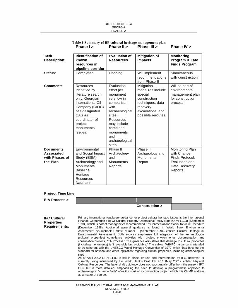
BTC PROJECT ESIAGEORGIA
FINAL ES IA
APPENDIX E III CULTURAL HERITAGE MANAGEMENT PLANNOVEMBER 2002
E- III-8
Table 1 Summary of BP cultural heritage management planPhase I > Phase II > Phase III > Phase IV >
TaskDescription:
Identification of knownresources in pipeline corridor
Evaluation of Resources
Mitigation of Impacts
MonitoringProgram & Late Finds Program
Status: Completed Ongoing Will implement recommendationsfrom Phase II
Simultaneouswith construction
Comment: ResourcesIdentified by literature search only; Georgian International Oil Company (GIOC) has designated CAS as coordinator of projectmonumentsissues.
Evaluationeffort per monumentvery low in comparisonwitharchaeologicalsites.Resourcesmay include combinedmonumentsandarchaeologicalsites.
Mitigationmeasures include specialconstructiontechniques; data recoveryexcavations, and possible reroutes.
Will be part of environmentalmanagement plan for construction process.
DocumentsAssociatedwith Phases of the Plan
Environmentaland Social Impact Study (ESIA)Archaeology and MonumentsBaseline;HeritageResourcesDatabase
Phase II ArchaeologyandMonumentsReports
Phase III Archaeology and MonumentsReport
Monitoring Plan with Chance Finds Protocol; Evaluation and Data Recovery Reports
Project Time Line
EIA Process >Construction >
IFC Cultural PropertiesRequirements:
Primary international regulatory guidance for project cultural heritage issues is the International Finance Corporation’s (IFC) Cultural Property Operational Policy Note (OPN 11.03) (September 1998 ) which is part of that agency’s recommended Environmental and Social Review Procedure (December 1998). Additional general guidance is found in World Bank EnvironmentalAssessment Sourcebook Update Number 8 (September 1994) entitled Cultural Heritage in Environmental Assessment. Both sources emphasise full integration of the archaeological(cultural properties) compliance activities with project environmental documentation andconsultation process, “EA Process.” The guidance also states that damage to cultural properties (including monuments) is “irreversible but avoidable.” The subject WB/IFC guidance is intended to be coherent with the UNESCO World Heritage Convention of 1972 which “has become the standard for national and other legislation” regarding cultural properties, including archaeological sitesAs of April 2002 OPN 11.03 is still in place. Its use and interpretation by IFC, however, is currently being influenced by the World Bank’s Draft OP 4.11 (May 2001) entitled Physical Cultural Resources. The latter draft guidance does not substantially differ from the present IFC OPN but is more detailed, emphasizing the need to develop a programmatic approach toarchaeological “chance finds” after the start of a construction project, which this CHMP address as a matter of course.

BTC PROJECT ESIAGEORGIA
FINAL ES IA
APPENDIX E III CULTURAL HERITAGE MANAGEMENT PLANNOVEMBER 2002
E- III-9
Table 2 Periods of Georgian prehistory and history
Lower Palaeolithic (2,000,000-200,000 years ago). This is a time before the emergence of anatomically modern humans. Early members of the genus Homo (Homo erectus) lived in small bands, apparently foraging radially from a home base located near some key environmental feature.
Middle Palaeolithic (200,000-30,000 years ago). This very long period corresponds to the emergence of archaic Homo sapiens such as neanderthalensis.
Upper Palaeolithic (30,000 years ago - 12,000 BC). The Upper Palaeolithic corresponds to the Late Pleistocene period and saw the appearance in Europe, Southwest Asia and Georgia, of anatomically modern humans.
Mesolithic (12,000-8,000 BC). The start of Mesolithic Period is marked by the end of the Pleistocene epoch and the start of the Holocene. Retreat of the Würm glaciation created a more moderate climate allowing exploitation of a wider range of environments.
Neolithic Period (8,000-3,500 BC). The beginning of the Neolithic Period is sometimes referred to as a revolution because of the dramatic shift in the human economy that it brought—agriculture and the domestication of animals.
Bronze Age (3,500-800 BC/IV-I Millennia). Bronze Age cultures throughout Europe, the Mediterranean and Southwest Asia depended on the plant and animal domesticates andassociated technical advances such as pottery and the working of native metals, to build a new type of society. This new society was ruled by a military and priestly elite who apparently practised a religion that included elaborate burial rituals and specific belief in an afterlife in which worldly material goods were of value.
Iron Age (800-400 BC). Technological changes led to a larger more sedentary population which also appears to have made populations more prone to regional economic independence.
Ancient Period (500 BC-AD 458). Prehistory ends and Ancient History begins with the advent of a written historical record. Greeks, Achaemenid Persians and Steppe Nomads were the key influences during this period.
Medieval Period (Late AD 400s-1450s). The Georgian Christian tradition began shortly before the start of the Medieval Period when St. Nino came from Cappadocia (north-eastern Turkey) to evangelize in Georgia in the early fourth century AD.
Modern Period (AD 1450s -present). Historical themes of the Modern Period include internal political fragmentation in Georgia, as well as influence and aggression from a new mix of foreign powers vying for control of the area including: Ottoman Turks, Safavid Persians, Russian Empire and later Soviet Union.

BTC PROJECT ESIAGEORGIA
FINAL ES IA
APPENDIX E III CULTURAL HERITAGE MANAGEMENT PLANNOVEMBER 2002
E- III-10
Table 3 Archaeological sites identified for Phase II field investigation
SITE ID, UTMs & NEAREST KP PER
ROW VERSION 010
DISTRICT SITE NAME SITE DESCRIPTION BASEDON SURFACE OBSERVATION
BPGA-1(8461347-4598737)Nearest KP=74
Tetritskaro Daget Khachini Medieval Village Site. Structures, tile and ceramic fragments visible on surface. Pipeline appears to pass through southern edge of site. Confirmed by April ‘02 field visit.
BPGA-2(8450155-46026)Nearest KP=87
Tetritskaro Pump Station 2 Four apparent Early Bronze Age Tombs in Pump Station construction area; obsidian artifacts also found on surface in construction area. Confirmed by April ‘02 field visit.
BPGA-3((844 9450 – 460 3250)Nearest KP=88
Tetritskaro Tkemlana Medieval Village Site with crude boulder-work wall visible on surface. Site straddles creek and lies on south sloping hillside in forest. Confirmed by April ‘02 field visit.
BPGA-4(844 8240 – 460 4632)Nearest KP=90
Tetritskaro NadarbazeviVillage
Medieval Village Site located on south side of hill approximately 1km south of well known Nadarbazevi Palace which was avoided by earlier reroute. AD twelfth century, many structural remains visible on surface. Confirmed by April ‘02 field visit.
BPGA-5(8447991 – 460 6088)Nearest KP=92
Tetritskaro Takhtitskaro Medieval Site. Crude boulder-work walls visible onsurface. On South facing hillside. Confirmed by April ‘02 field visit.
BPGA-8(8429431-4614000)Nearest KP=114
Tsalka Eli-Baba(marginal areas)
Late Bronze Age Site. Late second millennium BC; Settlement with Cyclopean construction. Central area of Eli Baba was avoided by earlier re-route.This may be a multi-component site with remains on both sides of Beulchai Creek. Confirmed by April ’02 field visit.
BPGA-6(842 2566 – 461 2741)Nearest KP=122
Tsalka Aia Ilia Late Bronze/Early Iron Age Site. Early first millennium BC Cyclopean walls, Medieval Period site includes crude boulder-work, ruined church. Confirmed by April ‘02 field visit.
BPGA-7(841 8371 – 461 2541)Nearest KP=126
Tsalka Santa Village Middle Bronze Age Site. Third through second millennium BC, burial mounds and ritual roads, possible multiple burial tombs. This is a very large site that stretches about 2-3km along the pipeline alignment and is attributable to the Trialeti Culture. Larger, even more substantial, remains of the same period were avoided by re-route. Confirmed by April ‘02 field visit.
BPGA-9(838 2802 – 461 8698)Nearest KP=165
Borjomi Mt. Tavkvetili Middle Bronze Age Site. Third through second millennium BC, burial mounds. Apparently 2.5km S of present ROW. Field confirmation pending.
BPGA-10(838 3231-461 5137)Nearest KP=167
Borjomi Mt. Msralimta Middle Bronze Age Site Third through second millennium BC, two burial mounds visible from surface. Field confirmation pending.

BTC PROJECT ESIAGEORGIA
FINAL ES IA
APPENDIX E III CULTURAL HERITAGE MANAGEMENT PLANNOVEMBER 2002
E- III-11
SITE ID, UTMs & NEAREST KP PER
ROW VERSION 010
DISTRICT SITE NAME SITE DESCRIPTION BASEDON SURFACE OBSERVATION
BPGA-11/(838 0111 – 461 4516838 0400 – 461 4516838 0400 – 461 4382838 0553 – 461 4439838 0570 – 461 4304838 0643 – 461 4335838 0817 – 461 4452)Nearest KP=169
Borjomi Moliti Middle Bronze Age Site Third through second millennium BC, seven burial mounds. Field confirmation pending.
BPGA-12(8354540 – 4622800)Nearest KP=201
Borjomi Siliani Bronze Age Tombs, Possible Iron Age Tomb and Muslim Settlement. Site is 40m East of BPGA-13.CAS/URS field confirmation pending.
BPGA-13(835 4575 – 462 2807)Nearest KP=201
Borjomi Dgvari Middle Bronze Age Site. Third through second millennium BC; burial mounds and pit tombs. Site is 40m West of BPGA-12. CAS/URS field confirmation pending prior to subsurface evaluation.
BPGA-14(8345738 – 4619349)Nearest KP=213
Akhaltsikhe Agara Medieval Village Site. Located on south facing hillside overlooking Kura River. Confirmed by CAS/URS April site reconnaissance.
BPGA-15/(8318868–4608872)Nearest KP=247
Akhaltsikhe Orchosani Multi-Component site Bronze Age, Third through second millennium BC burial mounds; AD first millennium site settlement; AD 1600s site including ruined church with crypt.Confirmed by CAS/URS April ‘02 site reconnaissance.
(NOTE: BPGA-X is proposed as the internal project archaeological site code for Georgia to be used in archaeological field investigations and subsequently as a basis for artifact coding and subsequent curation. BPGA -x signifies ‘BP Pipeline Archaeology.’ The X signifies a sequential site number.)

BTC PROJECT ESIAGEORGIA
FINAL ES IA
APPENDIX E III CULTURAL HERITAGE MANAGEMENT PLANNOVEMBER 2002
E- III-12
Figure 1

BTC PROJECT ESIAGEORGIA
FINAL ESIA
APPENDIX E V – OIL SPILL RESPONSE PLANNOVEMBER 2002
BAKU – TBILISI – CEYHAN OIL PIPELINE PROJECT
Oil Spill Response Planning
Framework for Development of a Comprehensive Oil Spill ResponseCapability for the BTC Project
Document Number: BTC-PRO-REP-004
Rev No. Date Status Authors Approved Authorised0 28-3-02 Issue for Incorporation into ESIA HJR and
C&HD NeilsonJ Daniels
A Nesling

BTC PROJECT ESIAGEORGIA
FINAL ESIA
APPENDIX E V – OIL SPILL RESPONSE PLANNOVEMBER 2002
APPENDIX E ENVIRONM ENTAL IMPACTS AND MITIGATION
ANNEX V OIL SPILL RESPONSE PLAN
TABLE OF CONTENTSPage No
1 INTRODUCTION 11.1 Layout of the report 11.2 Overview of BTC project 21.3 The BTC boundaries 21.4 OSRP in context 31.5 Aims and objectives 31.6 Other projects in the region 4
2 POLICY, LEGAL AND ADMINISTRATIVE FRAMEWORK 52.1 Overview 52.2 Host government agreements (HGA) 52.3 Operating agreement for Turkey 62.4 International institutions and conventions 62.5 Other applicable regional initiatives 82.6 European Union 82.7 Partner policies and initiatives 8
3 OVERVIEW OF THE BP CRISIS AND EMERGENCY MANAGEMENTSYSTEM 9
4 OUTLINE OF THE AZERBAIJAN BUSINESS UNIT INCIDENTMANAGEMENT PLAN 104.1 Incident Management Plan (IMP) 104.2 Linkages between the IMP and oil spill response plan 134.3 Existing response plans 13
5 FRAMEWORK FOR THE OSRPS 155.1 Introduction 155.2 Definition of event severity 155.3 Risk assessment 165.4 Response plans 16
5.4.1 Inland spill response (containment manuals) 165.4.2 Marine and terminal operation and spill response 17
5.5 Trans-boundary response 175.6 Monitoring of spill progress 185.7 Salvage 18
5.7.1 Waste disposal 185.8 External contractor guidance 18
6 FRAMEWORK FOR RELEVANT SECTIONS OF OPERATIONSMANUALS & PROCEDURES 196.1 Overview 196.2 Linkages between operational & emergency documents 196.3 Integrity management 19
7 PHILOSOPHY FOR SELECTION OF OSR RESOURCES 21

BTC PROJECT ESIAGEORGIA
FINAL ESIA
APPENDIX E V – OIL SPILL RESPONSE PLANNOVEMBER 2002
7.1 Introduction 217.2 Planning standards 21
7.2.1 Linking risk assessment to OSRP 217.2.2 Logistics 227.2.3 Safety 22
7.3 Oil spill containment and clean-up equipment 237.3.1 Overview 237.3.2 Oil property considerations 247.3.3 Number of response units required 24
8 CONTAINMENT MANUALS 258.1 Onshore containment manuals 258.2 Coastal sensitivity and marine responce manuals 26
9 PRELIMINARY RESOURCE ESTIMATES 279.1 Emergency response centres 279.2 Tier 2 Response Equipment Storage Locations 279.3 Locations for landing tier 3 equipment 28
10 OSR DURING THE CONSTRUCTION PHASE OF BTC AND SD 3011 TRAINING 3112 SCHEDULE 32
TABLES
Table 1 Key roles as included in the Azerbaijan business units IMP 11Table 2 Overview of linkages between the Azerbaijan business unit IMP andthe OSRP documents 13Table 3 Preliminary assessment of locations for tier 2 response equipment 27Table 4 Landing locations for tier 3 equipment 28Table 5 Preliminary schedule for establishment of OSR capabilities for BTC 32
FIGURES
Figure 1 Overview of BTC project 3Figure 2 Administrative framework 5Figure 3 BP Incident management team and Azerbaijan management team organisation 12Figure 4 Linkages between the Azerbaijan IMP and country specific OSRP’s 14Figure 5 Linkages between operations and OSRP 20
Attachment A
Table of contents of BP Baku IMP

BTC PROJECT ESIAGEORGIA
FINAL ESIA
APPENDIX E V – OIL SPILL RESPONSE PLANNOVEMBER 2002
Acronyms and AbbreviationsAGT Azerbaijan – Georgia – Turkey Pipeline Project (includes BTC Oil Pipeline and
SCP Gas Pipeline)BMES Briggs Marine Environmental Services BMT Business Management Team BOTAS Boru Hatlari ile Petrol Tasima A.S. (Petroleum Pipeline Corporation
established by the Turkish Petroleum Corporation)BP British PetroleumBTC Baku-Tbilisi-Ceyhan Pipeline ProjectCEM Crisis and Emergency ManagementCONCAWE Conservation of Clean Air and Water in EuropeC&H Corbett and Holt LLC CM Crisis ManagerEARL East Asian Response Ltd ESIA Environmental and Social Impact AssessmentESPOO Convention on EIA in a Transboundary Context (Espoo, 1991)EU European UnionGCT Group Crisis TeamHGA Host Government AgreementIC Incident CommanderIFI International Financial InstitutionIGA Inter Government AgreementIMO International Maritime OrganisationIMP Incident Management PlanIMT Incident Management TeamIPIECA The International Petroleum Industry Environmental Conservation AssociationKura River Also known as the Mtkvari River in GeorgiaLLC Limited Liability CompanyLSTKA Lump Sum Turn Key AgreementMAP Mediterranean Action PlanMEP Main Export PipelineMOIG Mediterranean Oil Industry GroupNREP Northern Route Export PipelineOC On-scene CommanderOSIS An oil spill modelling SystemOSR Oil Spill ResponseOSRO Oil Spill Response OrganisationOSRP Oil Spill Response PlanOSRL Oil Spill Response Ltd RA Risk Assessment REMPEC Regional Marine Pollution Emergency Response Centre for the Mediterranean
SeaSCP South Caucuses Gas Pipeline Project (formally Shah Deniz Gas Pipeline
Project)SOCAR, State Oil Company of the Azerbaijan RepublicSRT Site Response TeamTPAO Turkiye Petrolleri Anonim Ortakligi (Turkish Petroleum Corporation)WREP Western Route Export Pipeline

BTC PROJECT ESIAGEORGIA
FINAL ESIA
APPENDIX E V – OIL SPILL RESPONSE PLANNOVEMBER 2002
E-V-1
1 INTRODUCTIONThis document provides the Framework for the development of the Oil Spill Response Plan (OSRP) for the Baku-Tbilisi-Ceyhan (BTC) project. It relates directly to the Risk Assessment (RA) for determination of release sizes and frequencies and to the potential environmental and social consequence of potential releases for the proposed BTC pipeline and its marine terminal at Ceyhan.
It describes existing and proposed actions needed to develop the BTC (OSRP), considering:
Existing spill response arrangements for the Western Route Export Pipeline (WREP) and the terminals at Sangachal and Supsa
Existing arrangements for the port of Ceyhan Specific oil properties relevant to
- the behaviour of the oil once spilt- the future selection of appropriate response equipment and techniques
A key element in this initiative is the harmonization of the elements of the existing contingencyplans for the WREP and its terminals, augmented where necessary to satisfy the additional requirements of the new BTC pipeline and its terminals. The final product is envisaged to be a single over-arching OSRP in Azerbaijan, Georgia and Turkey. This OSRP will cover not only BTC but also other projects operated by the BP Baku Business Unit.
BP has prepared this report with assistance from Corbett and Holt, LLC.
1.1 LAYOUT OF THE REPORTThis report has been set out in the following manner:
Section 1 Provides details of the BTC in context and also sets out the key elements of the Oil Spill Response Planning process including and important definitions
Section 2 Provides details of the Policy, Legal and Administrative frameworkSection 3 Sets out an overview of the BP incident management system Section 4 Outline of the Baku Business Unit Incident Management Plan (IMP)Section 5 Provides a Framework for the OSRP’s that will be developed for Azerbaijan,
Georgia and TurkeySection 6 Provides details of draft framework for relevant sections of operations manualsSection 7 Philosophy for selection of OSR equipment and locationsSection 8 Containment manualsSection 9 Provides an overview of Preliminary Resource EstimatesSection 10 Overview of the proposed OSR during the construction phase of BTCSection 11 Provides an overview of the approach to trainingSection 12 Establishes the proposed schedule for further development of the OSRP
documents and implementation of the Plan

BTC PROJECT ESIAGEORGIA
FINAL ESIA
APPENDIX E V – OIL SPILL RESPONSE PLANNOVEMBER 2002
E-V-2
1.2 OVERVIEW OF BTC PROJECTThe initial stages of the BTC project is being progressed by a group of oil companies including SOCAR, BP, Delta Hess, TPAO, Itochu, Unocal and Statoil. BP is the largest foreign oil company stakeholder and is leading the project development at this stage. For the purposes of this document, this group of sponsors is referred to as the BTC sponsors. Discussions with these and other potential stakeholders are ongoing in an effort to form a partnering group of oil companies to fund the project beyond the design phase.
The Project will comprise the following main facilities:
Approximately 1,700 kilometers of pipeline of nominal diameter between 42 and 46 inches commencing at Sangachal passing through Azerbaijan, Georgia and Turkish territory to Ceyhan
Pump stations (approximately 8, one of which may be deferred for several years) Intermediate pigging stations Associated block valves and other above ground facilities A marine terminal and loading facility at the Mediterranean port of Ceyhan
The detailed engineering design is currently being undertaken with the intention thatconstruction will commence in the latter part of 2002 / beginning of 2003. Commencement of pumping is planned for 2005.
Operation of the pipeline in Azerbaijan and Georgia will be the responsibility of an operating company currently being created by the International Oil Companies. BOTAS will beresponsible for operation of the Turkish section of the BTC project.
1.3 THE BTC BOUNDARIES For the purposes of this framework and subsequent OSRP’s , the extremities of the project areas are considered to be the fence line at Sangachal Terminal and the end of the loading arms at Ceyhan Terminal. Other notional boundaries will be important for determining BP and BOTAS’ responsibilities and assessing actual and potential environmental impacts. The latter areaddressed in the BTC Environmental and Social Impact Assessments (ESIAs).
In consideration of the international and regional regimes established for oil pollutionpreparedness and response, it is assumed that BTC OSRP will address spills emanating from the Sangachal terminal, the pipeline, and the Ceyhan Terminal loading or storage facilities, as described above, unless local requirements place additional legal responsibility on the BTC partners. Other spills, particularly those within Ceyhan Port, for example originating from a tanker, are assumed to be the responsibility of the ship operator and the host government. Non-withstanding the foregoing, BP and BOTAS should be prepared to act in accordance withinternal corporate policy should an oil spill occur outside the confines of the BTC project area.

BTC PROJECT ESIAGEORGIA
FINAL ESIA
APPENDIX E V – OIL SPILL RESPONSE PLANNOVEMBER 2002
E-V-3
Figure 1 Overview of BTC project
1.4 OSRP IN CONTEXTIt is recognized by BTC that it is necessary to both minimize the risk of a spill, and should a spill occur to reduce the potential for environmental damage. Such an integrated approachrequires the following to be taken into consideration:
Designing the pipeline system to ensure that the risks of incidents during operation areminimized
Constructing the project in a manner that minimizes risks of incidents Ensuring the pipeline is operated and maintained in a manner that minimizes the risk of
incidents Recognizing that incidents may occur and being aware of their consequences Ensuring appropriate emergency response resources and procedures are in place Ensuring appropriate training is undertaken
This framework has been developed as part of the preliminary work programme to address the latter two items. The other items are being addressed as part of the engineering design process for BTC.
1.5 AIMS AND OBJECTIVESThe aims and objectives of the proposed BTC OSRP will be to provide the means to:

BTC PROJECT ESIAGEORGIA
FINAL ESIA
APPENDIX E V – OIL SPILL RESPONSE PLANNOVEMBER 2002
E-V-4
Control a release, which may arise from a fault in the operation of the pipeline and associated facilities
Minimise the volume of such releases, when they do occur, by securing the source in the most appropriate way
Minimise the extent of movement of the released oil spill from the source, by timely containment
Minimise the environmental impact of primary releases by timely containment and recovery response
Maximise the effectiveness of the recovery response through the selection of both the appropriate equipment and the technique to be employed. This will be based on the knowledge of the relevant properties of the oil and the changes in their properties arising from the ambient conditions into which they are released and the sea and land conditions and morphologies onto which they are released
Maximize the effectiveness of the response through trained and competent, operational and response teams
1.6 OTHER PROJECTS IN THE REGIONBP and its partners, which include other oil companies, as well as governments and commercial entities active in the region, are considering a number of significant and related projects. Those of most relevance to BTC include:
The offshore full field development of the Azeri, Deepwater Gunashli, Chirag (AGC) field in the Caspian
The proposed offshore Gas development of the Shah Deniz field The proposed gas export pipeline project from the Shah Deniz field to Turkey – the
South Caucasus Pipeline Project (SCP)
The SCP and BTC projects follow similar proposed corridors, and have a number of common issues. Each project has a different partner set and schedule. Both are lead by BP and possible synergies are constantly assessed, particularly with regard to minimising the cumulativeimpacts.
The aspects of the OSRP discussed in this document, which are directly relevant to SCP include: Incident Management Planning and Oil Spill Response Planning activities associated with construction.

BTC PROJECT ESIAGEORGIA
FINAL ESIA
APPENDIX E V – OIL SPILL RESPONSE PLANNOVEMBER 2002
E-V-5
2 POLICY, LEGAL AND ADMINISTRATIVEFRAMEWORK
This section provides an overview of the relevant policies, legal and administrative framework in which the project as a whole is being implemented. Country specific information is provided in Section 6, Legislation and Policy Framework.
2.1 OVERVIEWThe Project is being implemented within the framework of the Inter-Government Agreements (IGAs) and Host Government Agreements (HGAs). In addition, a Lump Sum TurnkeyAgreement (LSTKA) with BOTAS forms the contractual basis for the construction phase of the Turkish section of the Project. Figure 2 depicts the framework under which these documents have been enacted.
Figure 2 Administrative framework
2.2 HOST GOVERNMENT AGREEMENTS (HGA)The HGA for each country is a key document setting out the obligations of the BTC partners and the Government within each respective country. Whilst the HGA for each country differs slightly, each contains words relating to the OSRP similar to the following:
“Prior to the completion of the Facilities and in relation to Pipeline Activities, a plan for Petroleum spill response capability (“Spill Response Plan”) as to spills within or that could
Funding & CoFunding & Co--operation Agreementoperation Agreement(including Business Framework)(including Business Framework)
Signed by BTC Investors and
SOCAR
Signed by BTC Investors and
BOTAS
Signed by Turkish Government and
BTC Investors
Signed by relevant Government and
BTC Investors
Signed and ratified by the three States
TurnkeyTurnkeyContractContract(BOTAS)(BOTAS)
GovernmentGovernmentGuarantyGuaranty
HostHostGovernmentGovernmentAgreementAgreement
HostHostGovernmentGovernmentAgreementAgreement
HostHostGovernmentGovernmentAgreementAgreement
InterInter--GovernmentalGovernmental
AgreementAgreement
InterInter--GovernmentalGovernmental
AgreementAgreement
InterInter--GovernmentalGovernmental
AgreementAgreement
TurkeyTurkeyGeorgiaGeorgiaAzerbaijanAzerbaijan
BTC PROJECT ESIAGEORGIA
FINAL ESIA
APPENDIX E V – OIL SPILL RESPONSE PLANNOVEMBER 2002
E-V-6
affect the Territory will be created and implemented by the MEP Participants. The Spill Response Plan will include:
(i) Environmental mapping of habitats vulnerable to potential petroleum spills in the entire MEP system
(ii) Situational scenarios of potential spillages and responses, taking into consideration local circumstances
(iii) Plans for the provision of relevant Petroleum spill clean-up equipment, materials and services
(iv) Plans for the deployment of relevant equipment and emergencyresponse notification details of the organisation required to handle Petroleum spill response
(v) Plans for the treatment and disposal of resulting contaminatedmaterials.”
MEP stands for Main Export Pipeline.
2.3 OPERATING AGREEMENT FOR TURKEYIn defining the terms for operation of the Turkish section of the system BP is in the process of negotiating an Operating Agreement with BOTAS. This document will set out the basis in which the OSR capabilities will be adopted and will include the requirement to:
Prepare an OSRP Establish the legal framework for response to oil spills Purchase OSR equipment Maintaining OSR equipment Undertaking training and providing for the necessary resources to enable an appropriate
response to an oil spill
Transboundary oil spill response issues, such as those between Azerbaijan and Georgia and Georgia and Turkey will also be addressed to facilitate an efficient oil spill response.
2.4 INTERNATIONAL INSTITUTIONS AND CONVENTIONSInternational, regional, and national legal regimes for oil spill preparedness and response have been established to address the basic principles of responsibility (liability), communication, and activities that need to be addressed in the OSRP. The host countries may be signatory to many or all of these conventions. The OSRP for each host country will have to address the institutional and legal requirements that may exist in each host country. For example, Turkey is signatory and party to the Barcelona Convention, and Georgia is signatory to the International Convention on Oil Spill Preparedness Response and Cooperation.1
Details of policies and conventions applicable in each country are provided in Section 6, Legislative and Policy Framework. An overview of the international instruments that may apply in one or more host countries and which may need to be addressed in each OSRP include:
Convention on the Transboundary effects of Industrial Accidents (Helsinki, 1992) Convention on EIA in a Transboundary Context (Espoo, 1991)
1 Azerbaijan is not currently signatory to these conventions, however, it may decide to accede to these or other conventions in the future.

BTC PROJECT ESIAGEORGIA
FINAL ESIA
APPENDIX E V – OIL SPILL RESPONSE PLANNOVEMBER 2002
E-V-7
Convention on the Protection and Use of Transboundary Watercourses and International lakes (Helsinki, 1992)
Convention on the Conservation of European Wildlife and Natural Habitats (Bern, 1979)
Convention on Persistent Organic Pollutants (Stockholm, 2001) International Convention on Oil Pollution Preparedness Response and Cooperation
(OPRC) International Convention for the Prevention of Pollution from Ships, 1973, as amended
(MARPOL 73/78) International Convention on the Establishment of an International Fund for
Compensation for Oil Pollution Damage, 1971 and Protocol
In addition to the treaties and conventions that may apply in each country, certain international institutions have established programmes that are available to assist countries in dealing with oil spills. In developing of the country specific OSRPs the following established policies andpractices may be of relevance:
United Nations Environment Programme - recent activities include ship/shore interface issues, chemical dispersants
Mediterranean Action Plan (MAP) - implementing the Barcelona Convention for pollution assessment and nature conservation
International Maritime Organisation - vessel related oil spill incidents Regional Marine Pollution Emergency Response Centre for the Mediterranean Sea
(REMPEC) - the regional oil spill combating centre for facilitating mutual assistance in the event of large oil spills
A key aspect of these conventions is the determination of who pays for the clean-up effort. In this regard, international instruments generally follow the principle of the “polluter pays” (to a prescribed limit of liability). Nation states, including the host governments of the BTC project, have an obligation to deal with oil spills within their territory and around their coasts in a manner consistent with the international laws and regional schemes to which they are party. Some governments, while not acceding to a particular convention, often apply its provisions as a matter of “customary law.” The reward for performing in a manner consistent with international law is the opportunity to claim reimbursement for costs and damages incurred for an incident from either the party responsible for the oil spill or, in certain instances from the existing Global Compensation Regimes.

BTC PROJECT ESIAGEORGIA
FINAL ESIA
APPENDIX E V – OIL SPILL RESPONSE PLANNOVEMBER 2002
E-V-8
2.5 OTHER APPLICABLE REGIONAL INITIATIVESThere are a number of initiatives currently in place or being developed including:
Convention on the Protection of the Black Sea against Pollution (Bucharest, 1994) Convention for the Protection of the Mediterranean Sea against Pollution, 1976 (the
Barcelona Convention). The Barcelona Convention and Protocol have been developed as mechanisms through which the members undertake to use their best endeavours to provide each other with assistance in the event of a oil spill incident in the geographic areas covered by the agreement
Protocol Concerning Cooperation in Combating Pollution of the Mediterranean Sea by Oil and Other Harmful Substances in Cases of Emergencies
Mediterranean Oil Industry Group (MOIG). The International Petroleum IndustryEnvironmental Conservation Association (IPIECA), comprising petroleum companies and associations around the world, established the Mediterranean Oil Industry Group (MOIG) as the means for providing a regional oil industry forum on oil spillpreparedness and response for the Mediterranean Region. It provides a regional industry interface with REMPEC. BP and other BTC partners are key members of both IPIECA and MOIG
In addition BP is a member of an industry lead initiative on oil spill response related issues for the Caspian and Black Sea “region”. Members of Oil Companies operating in the region have established a Steering Group and working groups for the Caspian and Black Sea areas.
2.6 EUROPEAN UNIONWhilst none of the host countries are members of the European Union it is possible that one or more of these countries will join the EU during the life of this project. Should this occur, a EU host country will be bound by relevant EU legislation.
2.7 PARTNER POLICIES AND INITIATIVESNotwithstanding the various legal regimes that might apply to the BTC project, it is anticipatedthat the HGA and internal BP policies and practices, which represent industry “best practices,” will apply to oil spills from the BTC project in the absence of other more rigorous international or regional standards. Subsequent sections of this report describe how the OSRP developed as part of the BTC project development will be implemented in accordance with the BP Group Crisis Management System.

BTC PROJECT ESIAGEORGIA
FINAL ESIA
APPENDIX E V – OIL SPILL RESPONSE PLANNOVEMBER 2002
E-V-9
3 OVERVIEW OF THE BP CRISIS AND EMERGENCY MANAGEMENT SYSTEM
BP has instituted a Crisis and Emergency Management (CEM) System throughout its global operations. Emergency management plans are maintained to cover all of BP’s facilities,locations and products. Plans prepared under the CEM System identify equipment, training and personnel necessary to protect the workforce, customers, public, and environment, and BP’s reputation in the event of an incident. The expectations underlying the development of such a plan are:
Emergency Management Plans are based on the risks that potentially impact the business. These plans are documented, accessible, clearly communicated and align to the BP Group’s emergency management system
Equipment, facilities and personnel needed for emergency response are identified, tested and available
Personnel are trained and understand emergency plans, their roles and responsibilities, and the use of crisis management tools and resources
Drills and exercises are conducted to assess and improve emergency response/crisis management capabilities, including liaison with and involvement of externalorganizations
Periodic updates of plans and training are used to incorporate lessons learned from previous incidents and exercises
In a crisis event, there will be a maximum of three levels of management, with a clearly defined team leader at each level.
The Global Business Centre has a Crisis Management Plan detailing response to any crisis (in this case a potential or actual spill on the BTC system).
Each Region, in this case the Caspian Region, has a Regional Support Plan to enable the Regional Director and the Business Units in the area to link and assist each other.
Each Business Unit or group of Units will have a Business Support Plan. The Azerbaijan Business Unit (of which BTC is a part) has developed a Business Support
Plan that will assist the BTC in implementing the OSRP.
Each facility will have an Incident Management Plan (IMP) within an overall Incident Management System. The BTC OSRP will form part of the Baku Business Units IMP.
All plans are regularly tested through exercises to measure their effectiveness and to provide training for the response organisation.

BTC PROJECT ESIAGEORGIA
FINAL ESIA
APPENDIX E V – OIL SPILL RESPONSE PLANNOVEMBER 2002
E-V-10
4 OUTLINE OF THE AZERBAIJAN BUSINESS UNIT INCIDENT MANAGEMENT PLAN
Responsibility for construction and operation of the BTC project falls within the remit of the BP Azerbaijan business. Development of the necessary plans for BTC will therefore also beundertaken within the framework of the Azerbaijan Business units Incident management Plan and any associated plans. The following sections provide an overview of the existing documentswith particular emphasis on the OSRP’s currently in place.
4.1 INCIDENT MANAGEMENT PLAN (IMP) The BP Azerbaijan Business Unit IMP has been developed during the Early Oil Project and covers the procedures to be followed in the events such as:
Fires / Explosions Spills (Oil) / Releases (Gas) Injury / Casualty / Medevac Transportation Accident Natural Disasters
The IMP includes:
Policy and Expectations Response and Organization Notification and Callout Incident Management System Roles and Responsibilities Response Action Plans Forms Status Boards Meeting Agendas and Protocols Standard Operating Procedures
Relevant information from the existing Azerbaijan Business Unit IMP is included in this Framework document with a detailed table of contents included in Attachment A. The IMP will be updated to include BTC (including Turkey) within the same timeframe as for the OSRP as indicated in Section 12.
Key roles are set out in the existing IMP documents and are detailed in Table 1, with an organization chart shown in Figure 3.

BTC PROJECT ESIAGEORGIA
FINAL ESIA
APPENDIX E V – OIL SPILL RESPONSE PLANNOVEMBER 2002
E-V-11
Table 1 Key roles as included in the Azerbaijan business units IMP
Team Location Role Leader Title
Site Operations, or Project SiteResponse Team (SRT)
IncidentCommand Post,EmergencyScene
Initial Response, implementation of tactics, on-scenesafety
Facility, Operations or Project Manager or designate
On-sceneCommander(OC)
IncidentManagement Team (IMT)
IncidentManagementCenter (IMC), Baku
Tbilisi officeAnkara / Ceyhan
Strategy, tactics, logistics, agency liaison, finance/ admin., planning, ongoing operations
Incident Commander IncidentCommander(IC)
BusinessManagement Team (BMT)
BusinessManagementCenter (BMC), Baku
CrisisManagement,Policy, politicalliaison,externalaffairs,finance andlegal
BU Leader of Affected Business Unit or his nominee
Crisis Manager (CM)
Group Crisis Team (GCT)
BPGroupHeadquarters,London
Establish business response Strategy ensure that Group Concerns are appropriatelymanaged
BP GroupGCT member
GroupCrisis Manager

BTC PROJECT ESIAGEORGIA
FINAL ESIA
APPENDIX E V – OIL SPILL RESPONSE PLANNOVEMBER 2002
E-V-12
Figure 3 BP Incident management team and Azerbaijan management team organisation
BP Group Crisis TeamLondon
Incident Commander
SOCAR/GIOCGovernment
Organizations
Partners
BUSINESS MANAGEMENT TEAM (BMT)
HSEAdvisor
LegalAdvisor
HRAdvisor
GPA Advisor FinanceAdvisor
BUSINESS MANAGEMENT CENTER (BMC),ROOM 319 VP
Command StaffHealth & Safety Officer
Public Info OfficerLiaison Officer
HR Officer
Logistics SectionChief
Operations SectionChief
Planning SectionChief
Finance/Admin SectionChief
INCIDENTMANAGEMENT TEAM (IMT)
INCIDENT MANAGEMENT CENTER (IMC)ROOM 187, VP
On-scene Commander
Response Resources
SITE RESPONSE TEAM (SRT)INCIDENT COMMANDPOST (ICP)EMERGENCYSCENE
SOCAR/GIOCGovernmentOfficials
Emergency Response Coordinator
TbilisiSupport Units
Liaison OfficerSecurity Officer Logistics Officer
Public Info OfficerEnvironmental Officer
AdministrativeSupport
Staff
CrisisManager
Operations SectionChief
Staging Area ManagerSite Safety Officer
Deputy CrisisManager

BTC PROJECT ESIAGEORGIA
FINAL ESIA
APPENDIX E V – OIL SPILL RESPONSE PLANNOVEMBER 2002
E-V-13
4.2 LINKAGES BETWEEN THE IMP AND OIL SPILL RESPONSE PLAN
Table 2 provides an overview of the linkages between the various plans that will comprise the individual country OSRP with more details provided in Figure 4. Specific elements of these plans as they relate to response to incidents are described in subsequent sections of this report.
Table 2 Overview of linkages between the Azerbaijan business unit IMP and the OSRP documents
Azerbaijan Business Unit Incident
Management Plan
As described above this is the over arching documentthat details the procedures to be followed in response to any incidents in the BP Azerbaijan Business Unit region
Country Specific OSRP
Separate OSRPs will be developed for each country along the BTC corridor. These will be integrated with the existing OSRP’s prepared for the WREP, NREP and other onshore facilities
ContainmentManuals (Onshore)
Coastal Sensitivity and Shoreline
Protection Manuals
Offshore Response Manuals
These include specific proposed response and containment sites. Details such as environmental sensitivity, river (and sea current) data, maps and/or aerial photographs, etc
4.3 EXISTING RESPONSE PLANSWhilst this framework document is primarily focused on the BTC project the integration of BTC documentation into the IMP will be undertaken with due regard to the following existing plans:
WREP River containment and deployments manuals The Azerbaijan and Supsa shoreline containment manuals Continued use of the OSIS model for oil spill trajectory prediction into the response
arrangements for the Caspian Sea and at Ceyhan The work on weathering effects on the Caspian Crude oil now underway in Baku The existing containment and recovery provision at Ceyhan and the opportunity to
incorporate the OSIS model into the future response planning arrangements for the port

BTC PROJECT ESIAGEORGIA
FINAL ESIA
APPENDIX E V – OIL SPILL RESPONSE PLANNOVEMBER 2002
E-V-15
5 FRAMEWORK FOR THE OSRPS
5.1 INTRODUCTIONFor each country in the BTC system, a country specific OSRP will be developed to cover all of the facilities operated by BP and BOTAS. It is currently proposed that each OSRP will be structured in a similar manner to the IMP but will contain more specific information relevant to oil spill response. The contents of the OSRP are likely to include:
Response and Organization Notification and Callout Procedures Contact Details Roles and Responsibilities Definition of Event Severity Risk Assessment Response Action Plans
The first 4 items in this list will include extracts from or linkages to the IMP and will beaugmented by OSR specific elements. Further details on the latter 3 items in the list are set out below.
5.2 DEFINITION OF EVENT SEVERITYDefinition of a spill event in terms of Tier 1, 2 and 3 is recognized practice and is used to define spill size in the existing Azerbaijan and Georgia OSRP. Extracts from the existing OSRPdefinitions are set out below:
Tier 1 event A small local spill requiring no outside intervention and can be dealt with on site by local staff and stockpiled equipment.
Tier 2 event A larger spill that would require additional outside resources andmanpower.
Tier 3 event A large, possibly ongoing spill, which will require additional regional and possibly international resources. Such spills are very rare andwould only occur through full diameter pipe rupture, storage tankcollapse or a major tanker incident such as collision with another vessel.
The clean-up operation for a Tier 3 event will utilise all BTC OSR manpower and resources, and be augmented by additional resources from external contractors. Possible contractors include Briggs Marine Environmental Services (BMES) in Baku, Oil Spill Response Ltd. (OSRL) from Southampton, UK or the East Asian Response Ltd(EARL) in Singapore.

BTC PROJECT ESIAGEORGIA
FINAL ESIA
APPENDIX E V – OIL SPILL RESPONSE PLANNOVEMBER 2002
E-V-16
5.3 RISK ASSESSMENTThe OSRP will include relevant sections of the environmental risk assessment work undertaken as part of the BTC design. For onshore spills this section will discuss the various aspects that define the risk including:
Failure modes (3rd party damage, natural hazards, corrosion, operator error) Environmental receptors Spill volumes assessment Risk profiles
Similarly for offshore spills, the environmental risk assessment will address:
Likely causes of oil spills from the terminal and loading facilities Maximum and most probable release volumes
Further detail on the linkages between Risk Assessment and OSR planning to be used for BTC is set out in Section 7.
5.4 RESPONSE PLANSThere will be a number of specific response plans prepared as part of the overall OSRPincluding response plans for onshore and offshore spills as set out below.
5.4.1 Inland spill response (containment manuals)For each country, an Inland Spill Response Plan will be prepared that provides background information for OSR staff and operations staff. The dissemination of this information in the plans and in training modules will provide relevant members of the ORSP team with the necessary knowledge to make informed decisions in the event of an incident. The moremechanical aspects of oil spill response will be provided in the very specific containment manuals. Key elements to be included in the Inland Spill Response plans for each country may include:
Guidance on the Risk Models Guidance on the use of the GIS Guidance on the methods for prediction of oil movement from source of leak General information on containment and recovery of released oil either, on or within:
- Land- Rivers- Wetlands- Lakes- Forest- Archaeological sites
Disposal of waste arising from oil spill recovery operations Trans-boundary response Contractor guidance Secondary response

BTC PROJECT ESIAGEORGIA
FINAL ESIA
APPENDIX E V – OIL SPILL RESPONSE PLANNOVEMBER 2002
E-V-17
5.4.2 Marine and terminal operation and spill responseThe Marine and Terminal Spill Response may include:
Guidance on the Risk Models Oil Spill Tracking ie OSIS and other methods for Prediction of oil movement Containment and recovery of oil on:
- Sea- Wetlands- Beaches
Containment of oil at risk of release from marine installations and ships (marine salvage)
Selection and operation of shoreline cleaning techniques for the various shoreline types at risk, or actually polluted
Disposal of recovered oil and contaminated beach materials Trans-boundary response Contractor guidance Secondary response
A discussion on some of the key elements of the onshore and offshore plans is set out below with the equipment selection process described in Section 7.
5.5 TRANS-BOUNDARY RESPONSESufficient response capabilities will be established in each country to enable a Tier 2 incident to be handled using in country resources. Notwithstanding, BP will continue to consult with the boundary authorities in Azerbaijan, Georgia and Turkey to ensure Tier 2 equipment could be moved from country to country in the event of a spill. The OSRP will also address the responses required in the event of an oil spill occurring in one country that could potentially impact another country. An example of such an event could be an oil spill:
Into the Azerbaijan section of the Kura with potential to flow into the Caspian and hence to the waters of a Caspian littoral state other than Azerbaijan
Into the Kura River in Georgia with oil potentially passing into Azerbaijan Into the Kura or Posov Rivers in Turkey potentially passing into Georgia Into the Euphrates River in Turkey with oil potentially passing into Iraq An oil spill at the Turkish / Syrian border potentially effecting Cyprus and Syria
Appropriate provision will be included in the IMP and OSRP including:
Roles and responsibilities Contact numbers lists IMP – Mobilization of appropriate external response in the event that an oil plume may
impact on territories in which no OSRP capability or Inter- Government agreement exists
Containment Plans (ie identification of containment locations inside the Azerbaijan border to ensure a spill in Georgia can be appropriately contained when it crosses)

BTC PROJECT ESIAGEORGIA
FINAL ESIA
APPENDIX E V – OIL SPILL RESPONSE PLANNOVEMBER 2002
E-V-18
5.6 MONITORING OF SPILL PROGRESSThe OSIS model can be used to follow movement at sea and natural dispersion as a function of time and temperature. To complement the predictions from the OSIS modelling mechanisms for deployment of vehicles, vessels or aircraft will be established.
5.7 SALVAGESalvage is an important component of marine oil spill response activities, in that they serve as the principal means of securing the source of the release and minimising the amount of oil that may be lost. It is the responsibility of an affected ship’s owner to provide salvage resources, but it is incumbent on BP to be aware of salvage arrangements and activities in the event of a spill from a vessel associated with the BTC project. The OSRP will provide a summary of the main shipping company contacts and available salvage arrangements.
5.7.1 Waste disposalBP is currently undertaking a review of waste management issues to ensure adequate facilities will be in place to deal with wastes generated during the construction and operation of existing and proposed facilities in the region through which the BTC pipeline passes. In undertaking this assessment consideration of possible wastes arising in the unlikely event of an oil spill is being addressed.
Should an event occur an important part of the secondary response will be consideration of where wastes are transported to and how they are treated. In making this assessment it will be important for the decision maker to understand that there will be environmental impactsassocia ted with any disposal option and these will be to be assessed as part of the decision making process.
5.8 EXTERNAL CONTRACTOR GUIDANCEExternal contractors are likely to be identified as an important resource to be called on in the event on an oil spill or other incident. The OSRP will provide details of the contractors with which BP and or BOTAS has agreements with to assist in such events. Reference will be made to documents that clearly set out the account manager and terms of engagement for the various contractors.
BTC PROJECT ESIAGEORGIA
FINAL ESIA
APPENDIX E V – OIL SPILL RESPONSE PLANNOVEMBER 2002
E-V-19
6 FRAMEWORK FOR RELEVANT SECTIONS OF OPERATIONS MANUALS & PROCEDURES
6.1 OVERVIEWFigure 5 provides a generic structure of the various documents, which control the Management, Operational, Repair and Emergency activities on a typical pipeline system. The BTCdocumentation system will be structured to provide information, guidance and instruction to ensure that the safety, operability and integrity of the pipeline is maintained throughout its lifetime.
6.2 LINKAGES BETWEEN OPERATIONAL & EMERGENCYDOCUMENTS
Where required, linkages between the Operational & Emergency documentation, will beprovided, within the text of the documents, to ensure that, in the event of an emergency, the Pipeline Operators are provided clear directions to enable them to take the appropriate actions quickly and efficiently.
6.3 INTEGRITY MANAGEMENTBTC will develop an Integrity Management System, which will outline the processes by which the technical integrity of the BTC pipeline will be managed and assured.
The Integrity Management System will address the management and assurance processesrequired to:
Maintain the technical and operational integrity of the system Identify the system boundaries and components Demonstrate, by independent review, the delivery of technical and operational integrity Identify the roles and responsibilities of those persons involved in maintaining and
assuring the integrity of the system Ensure that the appropriate level of inspection, testing and review is maintained Ensure that operating limits and philosophies are consistent with the design intent and
reflect system changes and modifications Ensure that changes and modifications, to the system, are engineered and implemented
such that the integrity of the system is not compromised
The Integrity Management System plays a critical role in the prevention of oil spills. A primary element in developing the Integrity Management System, will be the Pipeline Risk Assessment Process where, for each component of the pipeline system, the threats and the probability andconsequences of the threats will be evaluated to derive the maintenance and inspection intervals for the various elements of the pipeline system.


BTC PROJECT ESIAGEORGIA
FINAL ESIA
APPENDIX E V – OIL SPILL RESPONSE PLANNOVEMBER 2002
E-V-21
7 PHILOSOPHY FOR SELECTION OF OSR RESOURCES
7.1 INTRODUCTIONThe immediate response and containment actions developed will be based on the following parameters:
Linking the response capability to the risk assessment process Further defining what constitutes Tier 1, 2, and 3 for the different components of the
BTC system Assuring that response activities are planned with due regard to logistical and safety
considerations Considering oil properties and national and regional priorities in selection of response
strategies
7.2 PLANNING STANDARDSThe parameters required to achieve an effective response will be defined in the OSRP planning standards. Development of these standards will include consideration of travel times, people and equipment and will be linked to the Risk Assessment process as discussed below.
7.2.1 Linking risk assessment to OSRPAs described in the ESIA, an assessment has been undertaken to understand the possible spill scenarios that could be expected along the BTC pipeline. The assessment is consideredconservative as it is based on historical pipeline performance data (CONCAWE) and does not take into consideration:
Improvements in pipeline design techniques Improvements in asset management methodologies including the use of intelligent
pigging
Notwithstanding the conservative assumptions made in the risk assessment the outputs will however, be very useful in enabling the oil spill response planners to define the appropriate resources that should be employed for the BTC pipeline. In particular the outputs from the risk assessment will be used to determine what “Tier 2” resources shall be employed. Inconsideration of the outputs from the risk assessment consideration will be given to having different response strategies dependant not only on the probable leak size but also on thesensitivity of the environment in the leak location.
An environmental risk assessment is also being undertaken for the terminal and loadingfacilities. The findings from this assessment will be used in defining the appropriate OSRP resources and particularly the Tier 2 response capability to be obtained and operated by BOTAS on behalf of the BTC partners.

BTC PROJECT ESIAGEORGIA
FINAL ESIA
APPENDIX E V – OIL SPILL RESPONSE PLANNOVEMBER 2002
E-V-22
7.2.2 LogisticsIn development of the complete OSRP and the associated selection of equipment and storage locations the following aspects will be considered:
Access -There are several long reaches of pipeline that have no access excepting the BTC right-of-way itself. In these reaches of pipeline, it is likely that during the winter months oil spill response personnel and equipment will have to be transported to the spill site via helicopter, or surface vehicles suitable for over-snow transport. This will influence the size and type of containment equipment selected. Where the pipeline parallels or crosses waterways, or where a spill may enter a major waterway, water-borne transport may be required. This will also affect the type of containment equipment selected
Local infrastructure varies significantly along the BTC alignment. Where available and competent local infrastructure will be incorporated in the plan
Terrain also varies significantly along the BTC alignment with the mountainous areas in Georgia and Turkey inhibiting the ease of access
The logistics of equipment deployment will be based on:
Amounts and types of equipment available for use in the three countries involved Availability of equipment in immediately contiguous regions Cross border clearance times Availability of equipment from out of area stockpiles
It is necessary to have enough equipment to adequately respond to a Tier 2 spill located in each BTC country, due to the difficulty of moving equipment across borders. Additionally, this equipment will be strategically placed at locations that allow response personnel to deploy it at appropriate sites. The equipment will be generally dedicated to the BTC, and purchased and maintained by the systems operators, however, it must be acknowledged that oil spills do not lend themselves to predicable responses and may require other types of equipment andprocedures not normally thought of as dedicated equipment, such as earth moving equipment. BTC personnel and equipment will be augmented by regional response organizations. When future regional Oil Spill Response Organizations (OSROs) are organized, BTC will arrange for them to also augment internal BTC resources.
7.2.3 SafetyNotwithstanding the above strategies, BP has developed procedures to ensure the safety of personnel and the public and include:
Restrictions on vehicle speeds with vehicles towing trailers stipulated to travel at slower speeds. Restriction on the amount of night driving
Safety issues associated with working in the vicinity of high pressure gas pipelines (ie the SCP)
These policies will be considered in determining appropriate storage locations of OSRequipment and staff.

BTC PROJECT ESIAGEORGIA
FINAL ESIA
APPENDIX E V – OIL SPILL RESPONSE PLANNOVEMBER 2002
E-V-23
7.3 OIL SPILL CONTAINMENT AND CLEAN-UPEQUIPMENT
7.3.1 OverviewOil spill containment and clean-up equipment is typically associated with marine spills. Much of the equipment used to deal with Inland spills, such as those which may occur from a pipeline, are modified versions of equipment developed for offshore use. To complement equipment designed for clean-up of spills on water general construction equipment, such as earth moving machinery, is often the most effective equipment in dealing with onshore spills.
Mechanical equipment, such as booms and skimmers, are effective in protected waters around harbours and bays, but have limited utility offshore. Additionally, most spills occurring in “near shore” areas can be expected to come ashore, despite best efforts to contain and control free floating oil, making shore clean-up equipment, such as excavators, backhoes and other general construction equipment, of great value for removing stranded oil and contaminated material.
Offshore spills may respond favourably to treating with approved chemical dispersants, under prescribed parameters, such as time, rate, and method of application. Lighter crude oils can be effectively treated with dispersants when the chemical is applied early in the spill before the oil has the opportunity to develop into an oil/water emulsion (sometimes called “mousse”).
Sometimes, the best option is the “no action” option. Certain sensitive environments can be more damaged by response activity than by the presence of oil alone. This response option needs to be carefully coordinated with national authorities to ensure that concurrence is obtained before the “no action” option is pursued.
Equipment required to deal effectively with an oil spill may include:
Immediate Response Equipment
Transportation (boats, trucks, trailers, planes, helicopters) Communications equipment Maps and positioning equipment Containment and removal equipment (booms, excavators, etc) Pumping equipment and associated hoses / pipes Storage facilities
Repair Equipment (welding machines, pipe patching kits, etc)
Spill Monitoring Equipment (aircraft, boats, trucks)
Secondary Response Equipment
Oil water separators
The list of possible equipment is not intended to be exhaustive, but to be representative of the type of equipment that may be considered in the OSRP. Specific response requirements will be articulated in the OSRP based on the assessed risk and the planning standards (section 7.1).

BTC PROJECT ESIAGEORGIA
FINAL ESIA
APPENDIX E V – OIL SPILL RESPONSE PLANNOVEMBER 2002
E-V-24
Earth moving equipment and other mechanisms for cleaning and removingcontaminated soils and sand
In addition equipment may be required for final restoration of impacted habitats, flora and fauna and cultural resources (reseeding capability, etc)
7.3.2 Oil property considerationsThe oil properties which determine the relative difficulty and extent of the response problem and hence the type and capacities of the required response equipment for any given release volume, location and ambient temperature are:
The pour point temperature, which determines whether the released oil will remain liquid or solidify after release
The distillation - temperature profile which determines the extent of evaporative loss on exposure to the air and hence the extent of reduction in the volume requiring recovery
The viscosity, asphaltene and wax content, of the transported oil which influence the viscosity and stability of the water-in-oil emulsions which form on contact agitation with water, and which subsequently determine the rates of natural dispersion
The value of the viscosity of the fully developed emulsions which also determine the selection of equipment for optimal recovery rates and whether dispersants are a viable option
7.3.3 Number of response units requiredThe decision as to how many response units of the various types should be provided, for the various application sites and conditions will be based on:
Expected spill volumes Expected treatment rates inherent to the equipment design and type Logistics of delivery to response sites

BTC PROJECT ESIAGEORGIA
FINAL ESIA
APPENDIX E V – OIL SPILL RESPONSE PLANNOVEMBER 2002
E-V-25
8 CONTAINMENT MANUALSAs set out in Figure 4 the key containment manuals for each country will be the onshore containment manuals and Coastal Sensitivities and Shore Protection Manuals. An outline of the information that will be included in these is set out below.
8.1 ONSHORE CONTAINMENT MANUALSThis volume will graphically display Maps and/or aerial photographs, and photographs will depict oil drainage pathways, specific immediate response and containment sites. This hard-copy volume will be supported by an interactive GIS system, which will display spill volumes and pathways for an event at any location along the BTC pipeline and terminals.
Specific response for all types of environmental receptor shall be included ie:
Rivers Lakes Wetlands Agricultural land Forests Areas used for extraction of groundwater Archaeological sites
At a minimum, each map and/or aerial photograph will display the following information:
Location Time and distances to each containment site Rendezvous point Forward holding positions Pipeline crossing location Containment sites Transfer station Site characteristics Access Storage
Details of the environmental aspects of the receptor and containment sites are also given ie:
River flow data. Environmental sensitivities. Other sensitive receptors ie power station intakes
Details of site specific oil spill response equipment is also given ie:
Limitations Recommended equipment (containment and recovery) Ancillary equipment Consumables

BTC PROJECT ESIAGEORGIA
FINAL ESIA
APPENDIX E V – OIL SPILL RESPONSE PLANNOVEMBER 2002
E-V-26
8.2 COASTAL SENSITIVITY AND MARINE RESPONCE MANUALS
The development of the Coastal Sensitivities and Marine Response Manuals will be undertaken in accordance with the regulations described in Section 2. In terms of specific BTCrequirements the HGA and operating agreements set out the main provisions for preparation of these reports and maps.

BTC PROJECT ESIAGEORGIA
FINAL ESIA
APPENDIX E V – OIL SPILL RESPONSE PLANNOVEMBER 2002
E-V-27
9 PRELIMINARY RESOURCE ESTIMATES A preliminary assessment of possible concepts for provision of oil spill response facilities has been undertaken as part of this framework assessment and is set out below.
9.1 EMERGENCY RESPONSE CENTRESEmergency response centres are likely to be located in Baku, Tbilisi and Ceyhan.
9.2 TIER 2 RESPONSE EQUIPMENT STORAGE LOCATIONS
Oil spill response equipment will be located at various locations within all three countries with possible locations as set out in Table 3.
Table 3 Preliminary assessment of locations for tier 2 response equipment
Country Location OSR Equipment for Offshore and Coastal
Clean-up
OSR Equipment for Spills from Onshore Facilities
Azerbaijan Baku / Sangachal
Offshore and Coastal clean-up equipment as part of the ACG response capabilities
WREP equipment augmented with equipment for BTC and SD as determined from assessment of response times and risks set out in this document
WREP PS 5
WREP equipment augmented with equipment for BTC and SD as determined from assessment of response times and risks set out in this document
WREP PS 8
WREP equipment augmented with equipment for BTC and SD as determined from assessment of response times and risks set out in this document
Georgia BTC PS G1
Equipment for BTC and SD as determined from assessment of response times and risks set out in this document
BTC PS G2
Equipment for BTC and SD as determined from assessment of response times and risks set out in this document
WREP PS 13
WREP equipment
WREP PS 15
WREP equipment
Supsa Offshore and Coastalclean-up equipment as part of the WREP response capabilities
WREP equipment
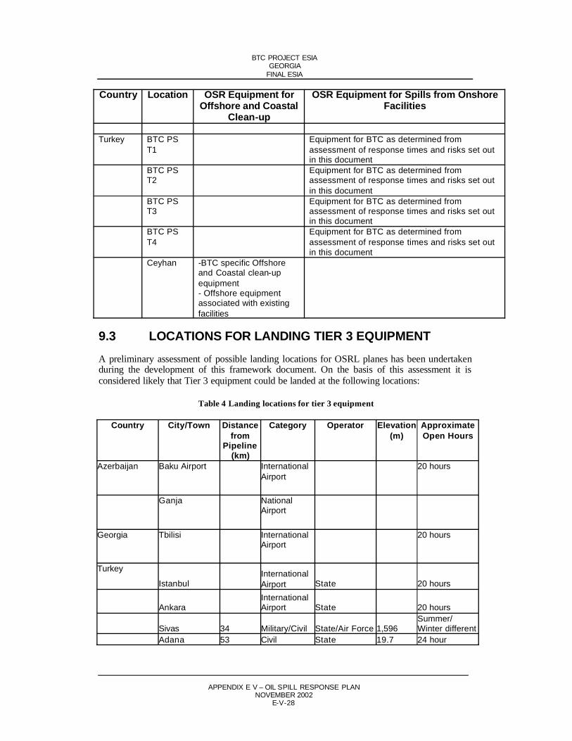
BTC PROJECT ESIAGEORGIA
FINAL ESIA
APPENDIX E V – OIL SPILL RESPONSE PLANNOVEMBER 2002
E-V-28
Country Location OSR Equipment for Offshore and Coastal
Clean-up
OSR Equipment for Spills from Onshore Facilities
Turkey BTC PS T1
Equipment for BTC as determined from assessment of response times and risks set out in this document
BTC PS T2
Equipment for BTC as determined fromassessment of response times and risks set out in this document
BTC PS T3
Equipment for BTC as determined from assessment of response times and risks set out in this document
BTC PS T4
Equipment for BTC as determined from assessment of response times and risks set out in this document
Ceyhan -BTC specific Offshore and Coastal clean-upequipment- Offshore equipment associated with existing facilities
9.3 LOCATIONS FOR LANDING TIER 3 EQUIPMENT A preliminary assessment of possible landing locations for OSRL planes has been undertaken during the development of this framework document. On the basis of this assessment it is considered likely that Tier 3 equipment could be landed at the following locations:
Table 4 Landing locations for tier 3 equipment
Country City/Town Distancefrom
Pipeline(km)
Category Operator Elevation(m)
ApproximateOpen Hours
Azerbaijan Baku Airport InternationalAirport
20 hours
Ganja NationalAirport
Georgia Tbilisi InternationalAirport
20 hours
Turkey
IstanbulInternationalAirport State 20 hours
AnkaraInternationalAirport State 20 hours
Sivas 34 Military/Civil State/Air Force 1,596Summer/Winter different
Adana 53 Civil State 19.7 24 hour

BTC PROJECT ESIAGEORGIA
FINAL ESIA
APPENDIX E V – OIL SPILL RESPONSE PLANNOVEMBER 2002
E-V-29
Country City/Town Distancefrom
Pipeline(km)
Category Operator Elevation(m)
ApproximateOpen Hours
Erzincan 16 Military/Civil State/Army 1153Summer/Winter different
Erzurum 2 Military/Civil State/Air Force 1757Summer/Winter different
Kahramanmaras 50 Civil State 525.1Summer/Winter different
Kars 22 Civil State 1795Summer/Winter different
Kayseri 90 Military/Civil State/Air Force 1052Summer/Winter different
Ardahan 6.1 Planned

BTC PROJECT ESIAGEORGIA
FINAL ESIA
APPENDIX E V – OIL SPILL RESPONSE PLANNOVEMBER 2002
E-V-30
10 OSR DURING THE CONSTRUCTIONPHASE OF BTC AND SD
Whilst the risk of oil and fuel spills during construction is significantly lower than that of the operations phase, there is some risk of spills from storage and transport of fuels and oil and during the refuelling process. To ensure an appropriate response to small events the construction contractors shall be required to maintain Tier 1 response equipment. This response capability will be augmented by the existing Tier 2 capability in place in Azerbaijan and Georgia.
A bridging document will be prepared for each significant contract to ensure appropriate incident response can be undertaken within the BP incident management system. These bridging documents will include the following elements / sections:
Purpose and Scope Call out procedure Call out of the BP Incident Management Team Call out of the Project Management Team Contact list for the Contractor’s sites (Site Response Teams)

BTC PROJECT ESIAGEORGIA
FINAL ESIA
APPENDIX E V – OIL SPILL RESPONSE PLANNOVEMBER 2002
E-V-31
11 TRAININGThe IMP and or OSRP and the Operations and Maintenance Manuals will include details of an ongoing training program. The documentation will be revised as required to reflect lessons learned during construction and operation of the system (ie continuous improvement).
The training programme will be designed to ensure that due regard is taken of outcomes from ongoing risk assessment with particular regard to environmental and socio-economic risks. The programme will be documented, accessible, clearly communicated and aligned to Business Unit and regional IMPs.
It is the intention to provide training of operatives at the various levels on a uniform basis across the three countries for both pipeline and terminal related spill responses, recognising that thesolution to inland and shoreline spill response problems share much in common.
The training courses will be designed to ensure appropriate levels of understanding are achieved at the different levels within the OSR team and will include:
Communications and decision-making Working with 3rd party contractors GIS and other tools Safety Region specific issues Discussions on the oil properties and how these change with environmental conditions
along the pipeline The relationship of oil properties and the approach to undertaking a response The selection and operation of appropriate equipment and techniques Maintenance of equipment and trouble shooting Deployment of equipment Free product recovery Waste disposal
The exercises will be designed to ensure the teams are fully aware of the procedures to be followed and have a clear understanding of how to use the various tools and equipment within the total range of chosen techniques. The training will highlight the importance of appropriate equipment selection and procedures to ensure the potential environmental impact of an event is minimized.
It is recognised that the results of training can only be fully realised if opportunities are provided for those trained to use their knowledge in suitably constructed drills and exercises. Examples of training exercises that may be undertaken include:
Notification exercises which, would involve unannounced checks on thecommunications systems and contacting key staff
Incident Management Team Exercises Partial activation exercises

BTC PROJECT ESIAGEORGIA
FINAL ESIA
APPENDIX E V – OIL SPILL RESPONSE PLANNOVEMBER 2002
E-V-32
12 SCHEDULEThis framework document has described the position now reached and the approach to be adopted for the creation of a fully comprehensive OSRP with all its associated equipment, manuals, and the guidance to be provided through training, drills and exercises.
Table 5 outlines the forward schedule:
Table 5 Preliminary schedule for establishment of OSR capabilities for BTC
Activity CompletionDate
Review of existing contingency plans Nov 2001Prepare Framework OSRP Dec 2001Issue Framework OSRP with ESIA Apr 2002Obtain acceptance of approach in Framework OSRP as part of ESIA approval Process
Aug 2002
Review existing equipment inventories 4 Q 2002
Identify types of suitable equipment having regard to oil properties for 4 Q 2002
i inlandii riveriii shorelinesiv water bornev sand/pebble washingvi waste recyclingvii final waste disposal
Consider numbers of the different types of equipment required, having regard to spill volumes and to:
4 Q 2002
i amounts and types already available in-houseii amounts and types held by contractorsiii amounts and types held by Tier 2 Contractoriv amounts and types held by OSRLv routes and capacities for waste recycling and disposalvi logistics considerations
Finalise Planning Standards 1 Q 2003
Complete Country Specific OSRP including BTC 1 Q 2003
Procure Equipment 2 Q 2003
Update IMP to include Turkey 2 Q 2003
Undertake consultation and data gathering with district leaders of potentially affected communities
3 Q 2003

BTC PROJECT ESIAGEORGIA
FINAL ESIA
APPENDIX E V – OIL SPILL RESPONSE PLANNOVEMBER 2002
E-V-33
Activity CompletionDate
Development of BTC Response Manuals: 3 Q 2003
1. Sensitivity mapping2. Pathway modelling3. Containment site selection4. Map preparation5. Identify equipment launch sites
Receive Equipment 4 Q 2003
Training for operations staff and OSRP staff operatives for spills to: 1 Q 2004
i inlandii riveriii shorelinesiv wetlandv sand/pebble washingvi waste management
Training for managerial and supervisory staff on: 1 Q 2004
i the content of the new Incident Response Planii the line operator's option to prevent or minimise releasesiii the basis for selection of clean-up methodsiv content of response manuals
Linefill Mid 2004

BTC PROJECT ESIAGEORGIA
FINAL ESIA
APPENDIX E V – OIL SPILL RESPONSE PLANNOVEMBER 2002
E-V-34
Attachment A
TABLE OF CONTENTS OF BP BAKU IMP
(Extracted from Document No UNIF-HSE-MA-400 Rev 0 April 2001 with proposed enhancements for BTC integrated plan in italics)
Section 0 Emergency Resources – Callout List
Emergency Response Resources and Contacts Development & Production (D&P) Business Management Team (BMT) Business Management Team (BMT) Advisers Support Group to BTC (Business Management Teams (BMT’s) Uxbridge/Sunbury, Shared Asset Emergency Support. Security Office Contact. Notification
and Primary Support Personnel IMT Members Emergency Stand by Vehicles Expertise Facilities IMC BMC Contacts Response Resources in Georgia Response Resources in Turkey Other useful Offices National Agencies and Officials Helicopter Contractor Vessel Contractor Operations Base Contacts Equipment External National Contractors External International Contractors External International Contractors’ Local Offices External Local Resources Baku External Local Resources Georgia External Local Resources Turkey FOC’s Contacts
Section 1: Policy and Expectatio ns
1.1 Policy1.2 Background1.3 Expectations1.4 General Objectives
1.4.1 Site Response Team (SRT)1.4.2 Incident Management Team (IMT)1.4.3 Business Management Team (BMT)1.4.4 Group Crisis Team (GCT)

BTC PROJECT ESIAGEORGIA
FINAL ESIA
APPENDIX E V – OIL SPILL RESPONSE PLANNOVEMBER 2002
E-V-35
1.5 IMS Custodian1.6 Testing and exercising
Section 2: Response and Organization
2.1 General2.2 Principles of Operation2.3 Levels of Events
2.3.1 Tier 1 (Minor Event)2.3.2 Tier 2 (Major Event)2.3.3 Tier 3 (Crisis)
2.4 Organization Structure2.4.1 General2.4.2 Response Teams Description
2.4.2.1 On-scene Commander (OC)2.4.2.2 Incident Commander (IC)2.4.2.3 Crisis Manager (CM)
2.4.3 Incident Management Team (IMT) – Organizational Structure2.4.4 Business Management Team (BMT) – Organizational Structure2.4.5 Combined IMT and BMT – Organizational Structure
2.5 IMT - BMT Liaison2.6 Post - Crisis Review
Section 3: Notification and Callout
3.1 Initial Notification3.2 Notification and Callout Procedure
3.2.1 Incident Commander3.2.2 Switchboard Operator
3.3 Incident Assessment and Notification Procedures3.4 IMT& BMT Callout and Activation3.5 IMT Callout3.6 BMT Callout3.7 IMT Incident Management Center (IMC) Activation3.8 BMT Business Management Centre (BMC) Activation3.9 Procedure for BTC Group Major Incident and High Potential Incident Reporting
3.9.1 Major Incident3.9.2 High Potential Incident3.9.3 Common Processes
3.10 Medical Team Callout3.11 Notification of Azerbaijan and Georgian Authorities
3.11.1 Emergency notification matrix for Azerbaijan3.11.2 Emergency notification matrix for Georgia
3.12 Notification of Shareholders and State Regulatory Bodies
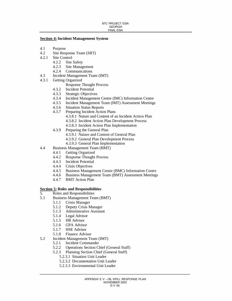
BTC PROJECT ESIAGEORGIA
FINAL ESIA
APPENDIX E V – OIL SPILL RESPONSE PLANNOVEMBER 2002
E-V-36
Section 4: Incident Management System
4.1 Purpose4.2 Site Response Team (SRT)4.2.1 Site Control
4.2.2 Site Safety4.2.3 Site Management4.2.4 Communications
4.3 Incident Management Team (IMT)4.3.1 Getting Organized
Response Thought Process4.3.2 Incident Potential4.3.3 Strategic Objectives4.3.4 Incident Management Centre (IMC) Information Centre4.3.5 Incident Management Team (IMT) Assessment Meetings4.3.6 Situation Status Reports4.3.7 Preparing Incident Action Plans
4.3.8.1 Nature and Content of an Incident Action Plan4.3.8.2 Incident Action Plan Development Process4.3.8.3 Incident Action Plan Implementation
4.3.9 Preparing the General Plan4.3.9.1 Nature and Content of General Plan4.3.9.2 General Plan Development Process4.3.9.3 General Plan Implementation
4.4 Business Management Team (BMT)4.4.1 Getting Organized4.4.2 Response Thought Process4.4.3 Incident Potential4.4.4 Crisis Objectives4.4.5 Business Management Centre (BMC) Information Centre4.4.6 Business Management Team (BMT) Assessment Meetings4.4.7 BMT Action Plan
Section 5: Roles and Responsibilities5. Roles and Responsibilities5.1 Business Management Team (BMT)
5.1.1 Crisis Manager5.1.2 Deputy Crisis Manager5.1.3 Administrative Assistant5.1.4 Legal Advisor5.1.5 HR Advisor5.1.6 GPA Advisor5.1.7 HSE Advisor5.1.8 Finance Advisor
5.2 Incident Management Team (IMT)5.2.1 Incident Commander 5.2.2 Operations Section Chief (General Staff)5.2.3 Planning Section Chief (General Staff)
5.2.3.1 Situation Unit Leader5.2.3.2 Documentation Unit Leader5.2.3.3 Environmental Unit Leader

BTC PROJECT ESIAGEORGIA
FINAL ESIA
APPENDIX E V – OIL SPILL RESPONSE PLANNOVEMBER 2002
E-V-37
5.2.4 Logistics Section Chief (General Staff)5.2.4.1 Procurement Unit Leader5.2.4.2 Security Unit Leader5.2.4.3 Transportation Unit Leader5.2.4.4 Communications Unit Leader
5.2.5 Finance/Administration Section Chief (General Staff)5.2.5.1 Accounting Unit Leader5.2.5.2 Insurance Unit Leader5.2.5.3 Administration Unit Leader5.2.5.4 Office Assistants/Translation Unit Leader
5.2.6 Health and Safety Officer (Command Staff)5.2.7 Public Information Officer (Command Staff)5.2.8 Liaison Officer (Command Staff)5.2.9 Human Resources Officer (Command Staff)5.2.10 Emergency Response Coordinator5.2.11 Baku, Tbilisi & Ceyhan Support Units
5.3 Site Response Team (SRT)5.3.1 On-scene Commander5.3.2 Site Safety Officer5.3.3 Staging Area Manager5.3.4 Aide(s)5.3.5 Source Control Branch Director5.3.6 Tactical Response Branch Director5.3.7 Pollution Control Coordinator
5.4 Switchboard Operator (Baku office)
Section 6: Response Action Plans
6.1 Fires/Explosions6.2 Spills (Oil)/Releases (Gas)6.3 Injury/Casualty/Medevac6.4 Fatality Checklist6.5 Transportation Accident6.6 Natural Disasters6.7 Additional BP Response Plan Links
Section 7: Forms
7.1 Forms used by the SRT Miscellaneous forms
7.2 Forms used by the IMT Incident Action Plan forms Miscellaneous forms IMT Worksheet for Determining Incident Potential
7.3 Forms used by the BMT Miscellaneous forms Major Incident and High Potential Incident Reporting forms
BMT Worksheet for Determining Incident Potential

BTC PROJECT ESIAGEORGIA
FINAL ESIA
APPENDIX E V – OIL SPILL RESPONSE PLANNOVEMBER 2002
E-V-38
Section 8: Status Boards
8.1 Status boards used by the IMT IMT Incident Facts Status Board IMT Incident Facts Update Status Board IMT Current and Forecast Weather Status Board IMT Safety and Health Considerations Status Board IMT Mass Balance Status Board IMT Sensitive Areas Status Board SRT Task Assignment Status Board IMT Tasks Status Board IMT Objectives Status Board IMT Organization Status Board Environmental Unit Summary Status Board IMT Schedule of Meetings Status Board IMT Notifications Status Board General Plan Status Board: Tasks and Durations General Plan Status Board: Equipment and Personnel Resources
Section 9: Meeting Agendas and Protocols
9.1 IMT Assessment Meetings9.1.1 Meeting agenda for IMT Assessment Meetings9.1.2 Meeting protocol for IMT Assessment Meetings
9.2 BMT Assessment Meetings9.2.1 Meeting agenda for BMT Assessment Meetings9.2.2 Meeting protocol for BMT Assessment Meetings
Section 10: Standard Operating Procedures
1. SOP-ADM-101 Preparation of Emergency Response Policies, Directives and SOPs
2. SOP-ADM-102 Handling Emergency Calls at Switchboard
3. SOP-CMD-201 Preparation of Site Safety Plan
4. SOP-CMD-401 External affairs during an Emergency or Crisis
5. SOP-CMD-601 IMC and BMC Setup
6. SOP-HR-102 Next of Kin Notification Plan
7. SOP-HR-103 Personnel Accounting System
8. SOP-HR-104 Survivor Reception Procedure
9. SOP-HR-106 POB Requirements and Distribution
10. SOP-LOG-301 Security for the IMC and BMC

BTC PROJECT ESIAGEORGIA
FINAL ESIA
APPENDIX E V – OIL SPILL RESPONSE PLANNOVEMBER 2002
E-V-39
11. SOP-LOG-302 VIP Visits to the Scene
12. SOP-LOG-501 IT/Telecom Plan
13. SOP-LOG-601 Transportation Procedures- Air
14. SOP-LOG-602 Transportation Procedures- Marine
15. SOP-LOG-603 Transportation Procedures-Land
16. SOP-PLN-201 Situation Unit Resources List
17. SOP-PLN-202 Gathering, Displaying and Maintaining Resource Status Information
18. SOP-PLN-203 Environmental Assessment, Priorities and Protocols
19. SOP-FIN-101 Finance Activities for Major Incidents

Page 1 of 1
7/23/2014https://web.archive.org/web/20120823065458/http://www.bp.com/liveassets/bp_intern...

BTC PROJECT ESIAGEORGIA
FINAL ESIA
APPENDIX E III - PHASE II ARCHAEOLOGY, STATEMENT OF WORKNOVEMBER 2002
APPENDIX E ANNEX III ATTACHMENT I
PROPOSED STATEMENT OF WORK FOR PHASE IIEVALUATION OF ARCHEOLOGICAL SITES IDENTIFIED INGEORGIAN PIPELINE COMPANY’S PROPOSED GEORGIANBTC AND SCP PIPELINE CORRIDORS
TABLE OF CONTENTSPage No
1 BACKGROUND 12 OBJECTIVES 13 SCOPE OF WORK 24 SCHEDULE 8
Table 1 Archaeological resources for Phase II site evaluation 9

BTC PROJECT ESIAGEORGIA
FINAL ESIA
APPENDIX E III - PHASE II ARCHAEOLOGY, STATEMENT OF WORKNOVEMBER 2002
E- III-I-1
Appendix E Annex III Attachment I
Proposed Statement of Work for Phase IIEvaluation of Archaeological Sites Identified in Georgian Pipeline Company’s Proposed Georgian BTC and SCP pipeline corridors
1 BACKGROUNDPursuant to cultural heritage law of the Republic Georgia and applicable international cultural heritage protection standards, the BP has established an archaeological protection strategy in consultation with the Republic of Georgia’s Center for Archeological Studies (CAS). The strategy will guide project archaeological work on the Georgian segment of the proposedAzerbaijan-Georgia-Turkey BTC and SCP pipeline corridors. CAS is the GeorgianGovernment’s cultural properties review and compliance agency, as specified in the GeorgianLaw on Cultural Protection.
Applicable international standards for the project inc lude World Bank OPN 11.03 entitled Cultural Property , a brief document that is in force pending release of forthcoming IFC OP 4.11 entitled Safeguarding Cultural Property in IFC-Financed Projects. Compliance with and appropriate consultation on these standards, as well as for the Georgian Law on Cultural Heritage, are an integral part of the BP's Environmental and Social Impact Assessment process for the subject project.
Phase I of the project’s Archaeological Strategy was carried out in order to identify potentially significant archaeological resources that could be impacted by construction. This identification study involved:
Review of literature Review of aerial of photographs Initial baseline surveys along possible right-of-way corridors Subsequent field assessment of identified sites as part of the project topographic survey
Based on these four types of investigation, fifteen of the sites identified by Phase I should be investigated by Phase II studies, ie site evaluation. Table 1 presents a list of these sites including a brief description of each.
2 OBJECTIVESFifteen potentially significant archaeological sites have been identified to lie within theGeorgian BTC and SCP pipeline corridors’s archaeological area of potential effects (APE). This corridor is approximately 50m wide and approximately 240km in length. Construction damage to the subject sites could cause a significant loss to the Republic of Georgia’s cultural heritage. To avoid such a potential negative impact, Phase II investigations are required at these sites to definitively evaluate the resources and to provide a basis for further protection measures if the sites prove to be significant. Such additional measures may include: site avoidance, data

BTC PROJECT ESIAGEORGIA
FINAL ESIA
APPENDIX E III - PHASE II ARCHAEOLOGY, STATEMENT OF WORKNOVEMBER 2002
E- III-I-2
recovery excavations prior to or during construction, or archaeological monitoring duringconstruction.
Phase II investigations should collect sufficient data to make final decisions about theimportance of each site; and in the case that a site is confirmed to be significant, theinvestigations should collect sufficient data on which to base a detailed work plan for archaeological impact mitigation measures, ie Phase III or Phase IV of the projectArchaeological Strategy.
3 SCOPE OF WORKThe above objectives of Phase II work at each of the fifteen subject sites will be achieved by the following tasks:
Task 1: Mobilization and Setup. This task addresses standard logistical and specific archaeological supply and equipment needs for the initiation of fieldwork in the project area. The task includes acquisition and packing of project vehicles with: camping supplies and equipment, archaeological field supplies and equipment; Personal Protective Equipment; required food, first aid equipment, and othersupplies. All required pre-field technical planning and technical briefing of crews by project senior technical staff will be carried out by this task. Senior staff of the field team will also review relevant literature reporting on previous investigations at the sites. Data collection procedures and forms will also be prepared and/or reviewed prior to departure for field. In sum, the task includes all preparatory activities required to initiate the fieldwork activities described in Task 2.
Beginning with Task 1 and continuing through the completion of Task 4, the field team will be subject to all normal BP consultant processes. For this project, these requirements will include, but not necessarily be limited to, the following:completion of BP land access process (including owner identification and owner compensation) for all fifteen sites to be investigated); BP logistics, planning and support process; BP security process; and BP HSE process.
In addition to the project technical report (Task 4), it will be the responsibility of the archaeological field team to prepare weekly status reports, monthly reports, valuations, and any required change orders.
All participants in the fieldwork will obtain or show evidence of having BPapproved medical insurance prior to the start of fieldwork.
Task 2: Fieldwork . Depending on the type of resources involved, Phase II investigations may, based on the judgment of project technical staff, include some or all of the following types of archaeological operations:
Initial Reconnaissance. This includes walkover investigation of site to identifysignificant surface-apparent archaeological features and natural or possibleanthropogenic topography indicative of subsurface resources. This and previous site documentation, if available, will provide a basis for establishing a plan for the sequenced investigation of the site. General surface collection of artifacts may be a part of this task. The task will also establish a permanent datum point from which to base site measurements and mapping operations. Subsequent base map

BTC PROJECT ESIAGEORGIA
FINAL ESIA
APPENDIX E III - PHASE II ARCHAEOLOGY, STATEMENT OF WORKNOVEMBER 2002
E- III-I-3
measurements and unit lay-out measurements may be made with a hand compass and cloth measuring tape, or with optical or laser surveying equipment depending on the circumstances. The task will also re-confirm that the site lies within the proposed corridor, identifying those portions of the site that is within the corridor and will therefore be investigated by Phase II fieldwork.
Systematic Surface Collections. This technique includes collection and ormapping-in-place of surface artifacts which may be indicative of horizontallocation of subsurface remains. Artifact densities are tallied according to recording blocks that are laid out relative the site datum and mapped on the site map. Blocks may be laid out with hand compass and cloth measuring tape at an appropriateinterval such as 5m, 10m, or 20m, which are marked with coloured pin flags.
Test Boring. This technique involves use of a hand auger and/or soil probe to identify possible natural and cultural soil characteristics including indicative soil characteristics such as colour, texture, compactness and possible artifact content. This technique can provide a general idea of the vertical and horizontal extent of possible natural and cultural stratigraphy of the site, but is usually not a reliable means of determining of the presence or absence, or vertical spatial configuration of subsurface artifact distributions.
Shovel Testing. This technique is used to identify the depth and horizontal extent subsurface artifact distributions. Shovel test locations are laid out at an appropriate interval such as 5m, 10m, and 20m using a hand compass and cloth measuring tape. Shovel test points are marked with pin flags or flagging tape. At each marked point on the measured grid, a shovel is used to excavate a circular holeapproximately 0.5m in diameter and extending through the topsoil and several cm into the subsoil. Soil colour and texture is noted and all soil removed from the test pit is passed through 4cm-gauge hardware-cloth screen mounted on wooden shaker frame. Artifacts recovered from the screen are segregated by shovel test with their generalized depth and soil matrix noted on a standard recording form. To increase the horizontal precision of the technique, additional pits, placed at a lesser interval, may be placed around positive shovel tests on the original grid. Shovel testing is a quick and accurate means of determining the horizontal distribution of subsurface artifacts, and providing guidance for the placement of larger, stratigraphicexcavation units. Results of shovel testing are usually plotted on a site map for ease of interpretation.
Test Unit Excavation. Stratigraphic test units are typically 1m x 1m or 2m x 2m units selectively placed to investigate the nature of cultural stratigraphy of areas indicated for investigation by boring, shovel tests, and or suggestive surfacefeatures. Smaller units are desirable for digging through deep stratigraphy to sterile soil. Larger units are appropriate where broader horizontal exposures are needed to support tentative spatial interpretations. Units are placed on the site grid and areplaced with a hand compass or cloth measuring tape or by optical or lasersurveying equipment. Units are marked for excavation with stakes and string to guide excavation and assist with three-dimensional recording of find locations. Units are excavated in arbitrary levels (5cm, 10cm, or 20cm), or in cultural levels. The starting and ending depths of the levels are measured from a local unit datum using a builder’s string level or a transit and stadia rod depending on thecircumstances. Recovered artifacts are segregated by level and special artifact finds

BTC PROJECT ESIAGEORGIA
FINAL ESIA
APPENDIX E III - PHASE II ARCHAEOLOGY, STATEMENT OF WORKNOVEMBER 2002
E- III-I-4
may be plotted in three dimensions and/or sketched in situ before removal. Soils and artifacts are described for each level and one or two wall profiles may be drawn in each unit to identify cultural and natural strata. Soil features of cultural origin such as hearths, storage pits, and middens may be sectioned and excavated separately. Such features are likely locations for the taking of charcoal samples for radio-carbon dating, and other types of special samples. Test units are usually not extended horizontally in Phase II work. Particularly productive Phase II units may be extended in Phase III. Test units are excavated using a range of manual tools ranging from shovel and pick to mason’s trowel. Unit walls and floors are scraped clean for drawing and photos with a trowel and may occasionally be sprayed with water to improve the definition of soil colour and cultural features.
Linear Trenching. Linear trenches are used to determine the location of subsurface architectural features including buildings, walls, stone, or plaster flooring, etc over relatively broad site areas. They allow near-surface features to be identified with a minimum of excavation. Typical dimensions of such units are 0.5m wide by 0.5m deep. Because of their narrow width, these trenches may be extended rapidly over relatively great distances across a site. Several perpendicular trenches may be placed across the apparent site boundaries to start with, followed by trenches positioned specifically to follow or extend from walls or other features that arefound in the initial trenches. The trenches are laid out and recorded on the site map using the same techniques as are employed for stratigraphic units. Linear trenches are typically not designed for stratigraphic recovery of artifacts and may be excavated in a single level depending on the circumstances.
Mechanical Soil Removal (prior to manual investigation). A back-hoe Gradall or other mechanical equipment will be used to remove culturally sterile soiloverburden. This technique would be necessary where the shallowest site deposits are buried beneath more than 20cm of culturally sterile soil. This speeds the siteexcavation process by avoiding the necessity of hand excavating large quantities of sterile soil. This would be especially needed in alluvial settings where soilaccumulation has been relatively rapid since site abandonment.
Note-Taking and Photography. All daily fieldwork activities including, but not limited to, the implementation of the above tasks will be recorded in narrative form in dated notebook entries of the archaeological staff assigned to each team. Inaddition specific redundant “unit” data such as those for shovel tests and test units, will be recorded on standard forms to allow efficient and standardized recording. Unit sketches and interpretive summaries will also be compiled. A systematic photo record will also be kept for all operations, including sample recording of typical site activities in progress as well as standardized and specific purpose level, profile, and final unit photos. The site, date and subject of all photos will be recorded in a photo log. A photo board will also be used when needed. All daily notebook entries and field forms completed will be have date, site name (egGECA-1), and investigator initials recorded along with all other required technical information.
Site Mapping, Drawing and Spatial Recording. All field operations will berecorded on a site map which may be created by several different mappingtechniques: hand compass and cloth tape; theodolite with surveying tape; or optical or laser transit. Surface and subsurface architectural foundations and floors will be

BTC PROJECT ESIAGEORGIA
FINAL ESIA
APPENDIX E III - PHASE II ARCHAEOLOGY, STATEMENT OF WORKNOVEMBER 2002
E- III-I-5
drawn and relative elevations of the ground surface may also be recorded with point elevations or contour lines. Field finds and subsequent interpretativeinformation established in Task 3 and Task 4 will be entered in a GISarchaeological data layer following BP project protocols for electronic mapping.
Backfilling and Stabilization. Following Phase II excavation, all units will be backfilled and stabilized to preserve unearthed archaeological features and to avoid danger to animals, humans and vehicles that my pass near the work site.
Task Summary. The guiding objectives of the fieldwork will be three-fold: 1) collect sufficient data to confirm significance of each site and, 2) if the site is significant, to collect sufficient data to support a detailed work-plan for Phase III data recovery investigations which would rescue the significant data and artifacts and 3) collect data in sufficient detail and in sufficiently organized manner tosupport the level of analysis and reporting described for Task 3 and Task 4described below.
Task 3: Laboratory Processing and Analysis. Crew will return from field to commence laboratory work immediately following fieldwork. Laboratory work will include the following procedures.
Field Note Review. On return from the field all field notes will be reread for clarity and to resolve inconsistencies. Notes will be entered into word processing software for ease of reference. All field photographs will be printed and labelled.
Special Analyses. Special samples collected for pilot analyses will be presented to specialized laboratories for analysis.
Artifact Processing. Artifacts will be washed and labelled with catalog numbers using standard archaeological laboratory techniques.
Artifact Cataloging. Artifacts will be identified using standard catalogingtechniques. They will be assigned to standard categories corresponding to material, artifact form, and morphological part present. Diagnostics will be identified as to date and cultural affiliation.
Data Entry and Quantitative Summary of Catalog Data. Catalog data will be entered in an electronic spreadsheet to facilitate printing of paper catalog and to support quantitative summary of artifact data in tabular and chart form.
Graphics, Drafting and Photography. Site maps, and selected plan and profile drawings will be finalized for inclusion in report. Field photos will be selected to include in the report.
The overall objective of this task is to process and stabilize artifacts for museum curation, and prepare numerical and graphical data for narrative interpretation for report of investigations as described below under Task 4.
Task 4: Technical Report Preparation. Findings and interpretations resulting from the previous tasks will be summarized and presented in a report following appropriate and customary archaeological procedures and conforming to text, graphical, and

BTC PROJECT ESIAGEORGIA
FINAL ESIA
APPENDIX E III - PHASE II ARCHAEOLOGY, STATEMENT OF WORKNOVEMBER 2002
E- III-I-6
data presentation standards of contemporary consulting archaeology reports. The report will present data and interpretation regarding the site’s age, culturalaffiliation, and function. Data will be presented in graphics, text, tables, andphotos. A major focus of the report will be the coherent presentation of apparent vertical and horizontal extent of the each site and its apparent depositional history.The report will also include a site map, artifact drawings and or photographs, and soil profile drawings.
The report should include the following or equivalent chapters and sections:
I. Abstract - Brief summary of salient report data including any recommendations for additional work (1-5 pages).
II. Introduction - Background data needed to understand report context, description of pipeline project, summary of study objectives, summary of report contents (5 pages).
III. Regulatory Background - Description the National and Internationalrequirements (5 pages).
IV. Environmental Setting - Description of overall all environmental setting of pipeline with emphasis on features likely to support archaeological interpretation (10 pages).
V. Cultural Background - Brief overview of archaeological and cultural sequence of the project area. Emphasizing past cultural developments related to studied archaeological remains (15-20 pages).
VI. Methodology - Description of general field methodology employed in the course of the fieldwork (10 pages).
VIII. Fieldwork Description - Narrative description of work actually conducted at each site with brief reference to findings. Will serve as description of scope of work executed (10-15).
IX. Discussion and Evaluation of Site Findings - Include site-by-site description of artifacts, stratigraphy and soil or architectural features. stratigraphic drawings, site maps and architectural and (20-25 pages).
X. Recommendations - Detailed recommendations for future work, if needed, will be provided for each site. In the case that additional work is recommended, this section will provide specific recommendations regarding scope-of-work (15pages).
XI. Bibliography
XII. Appendices including: artifact catalog; results of special analyses and studies; and any extended tabular or numerical data not appropriate for chapterpresentation.

BTC PROJECT ESIAGEORGIA
FINAL ESIA
APPENDIX E III - PHASE II ARCHAEOLOGY, STATEMENT OF WORKNOVEMBER 2002
E- III-I-7
The above-described technical report will be prepared in draft and final forms. Client comments will be addressed and the report finalized by the project teamwithin three weeks of receipt of comments.
Scoping assumptions
This scope of work is based on the key assumptions listed below:
a) The present proposal addresses Phase II investigation of the fifteen subject sites lying within the approximately 50m-wide project corridor only. Any sites lying within the impact zone of proposed temporary or permanent project infrastructure facilities are not included in the present scope of work.
b) Phase I investigation of the BTC and SCP pipeline corridors has not included subsurface site prospect ion. It is therefore anticipated that subsurface archaeological resources without obvious surface indications may be encountered during construction.Investigation of such resources is not included in Phase II. Phase IV of the project’s Archaeology Strategy would address protection of such resources.
c) All fieldwork and associated preparatory and support activity will be planned and executing following the HSE plan to be developed by the archaeological team prior to award of contract.
d) It is understood that Phase II fieldwork will continue only as long as seasonally variable weather conditions allow. Early suspension of fieldwork, or the prospect of it, may require modifications in approach to the fieldwork.
e) Duration of site investigations should vary between a 2-day minimum and 3-weekmaximum. The decision as to the investigation time required for each site will be made in the field by the Expedition Leader based on the findings of initial reconnaissance and any subsequent tasks that he may choose to initiate. Factors to be taken intoconsideration include the following: evident size, importance, and complexity of the site; progress and finding of investigation at other sites assigned to the field team; anticipated fieldwork time remaining prior to onset of inclement weather. This proposal assumes an average investigation time falling between 1-2 crew weeks per site and thus 14 to 28 crew weeks in total and 5-10 calendar weeks for fieldwork completion.
f) Collection of special samples for analysis will be limited to that amount needed toevaluate future analytical potential for Phase III. This includes, but is not limited to: charcoal from cultural contexts for radio-carbon dating; soil samples for recovery of micro- and/or macro botanical remains, or other chemical analyses; deposits containing paleo-zoological remains for species identification; physically fragile or chemically unstable materials that may need immediate and specialized conservation. In general, the recovery of special archaeological samples will be limited to small amounts required by any “pilot analyses” that may be required to define the scope of possible Phase III investigations.
g) Any articulated human remains and/or recognizable human burials of any type that are found by Phase II investigations will be left in place for possible subsequent excavation in Phase III.

BTC PROJECT ESIAGEORGIA
FINAL ESIA
APPENDIX E III - PHASE II ARCHAEOLOGY, STATEMENT OF WORKNOVEMBER 2002
E- III-I-8
h) Approximately 1,000 artifacts per site will be recovered by the field investigation and will require cleaning, labelling, cataloging and basic conservation. The present scope of work includes clearing cataloging and simple conservation methods. Artifacts deemed to require special conservation treatments such as impregnation or other consolidation and stabilization treatments that may be required, are not included in this scope of work.
i) The level effort for processing and analysis (Task 3) and reporting (Task 4) will depend on the amount of excavation actually completed in the field and the quantity of artifacts recovered. As a guideline, approximately one week’s work each in processing and analysis (Task 3) and reporting (Task 4) is required for every week spent in the field (Task 2) using manual techniques. Mechanical excavation may require a proportionallygreater amount of corresponding processing and reporting time due to its more rapid recovery of artifacts and stratigraphic information.
j) Vehicle and heavy equipment used for fieldwork will be dictated by availability of suitable equipment that meet technical and safety requirements of the work. Dedicated drivers for the vehicles may be required, or drivers may be drawn from other staff positions described above depending on typical driving time required between site and field lodging site of the crew. Long daily drives to site would be incompatible with a crew members’ doubling as a driver.
k) The cost of purchase for existing 1:10,000 and 1:5,000 topographic maps covering each of the 14 Phase II sites will be included in the proposal so that each archaeological field team conducting the work may add new data to the maps during investigation; or maps will be provided by BP.
l) It is understood that the project sponsor will assist the field team by precisely locating the 500m project corridor at each of the fifteen sites subject to Phase II investigation at the outset of the fieldwork.
m) It is understood that the corridor for investigation is to be 50m in width. Phase IIarchaeological work will be carried out within that corridor, except in the case of investigation of a possible minor re-route needs to be investigated and cleared, or that a minor expansion of investigation was required outside of the corridor for reasonsarchaeological interpretation.
4 SCHEDULEBased on the above task descriptions and assumptions, it is estimated that the entire Phase II project will take 15-30 weeks to complete following notice to proceed: 5-10 weeks in the field (assuming the use of multiple field teams working in parallel); and 10-20 weeks in artifact processing and preparation of the draft report.

BTC PROJECT ESIAGEORGIA
FINAL ESIA
APPENDIX E III - PHASE II ARCHAEOLOGY, STATEMENT OF WORKNOVEMBER 2002
E- III-I-9
Table 1 Archaeological resources for Phase II site evaluation
Site ID and KP District Site Type Site DescriptionSCPA-1 Tetritskaro Daget Khachini
SettlementMedieval. Found some tile and ceramic fragments.
SCPA-2 /(844 9450 –460 3250)
Tetritskaro TkemlanaSettlement
Medieval. Crude boulder-work(wall).
SCPA-3/(844 8240 –460 4632
Tetritskaro Nadarbazevi IISettlement
Medieval. Crude boulder-work.
SCPA-4/(844 7991 –460 6088)
Tetritskaro TakhtitskaroSettlement
Medieval. Crude boulder-work(the walls of different directions).
SCPA-5/(842 2566 –461 2741)
Tsalka Aia-Ilia Settlement The beginning of I millennium BC. Cyclopean settlement, medieval church.
SCPA-6/(841 8371 –461 2541)
Tsalka Santa, graves, tombs, ritual roads, III-II millennium BC
III-II millennium BC. Burial mounds, ritual roads, possible burial tombs.
SCPA-7 Tsalka Eli-BabaSettlement, tombs
The second part of II millennium BC, cyclopean settlement.
SCPA-8/(838 2802 –461 8698)
Borjomi Tavkvetili, burial mounds
III-II millennium BC.
SCPA-9/(838 3231-461 5137)
Borjomi Mt. Msrali mta, 2 burial mounds
III-II millennium BC (?).
SCPA-10/(838 0111 – 461 4516838 0400 – 461 4516838 0400 – 461 4382838 0553 – 461 4439838 0570 – 461 4304838 0643 – 461 4335838 0817 – 461 4452)
Borjomi Moliti, 7 burial mounds
III-II millennium BC (?)
SCPA-11/(835 4540 –462 2800)
Borjomi Siliani, tomb Bronze age tomb, possible I millennium BC tombs. Also Muslim (?) settlement.
SCPA-12/(835 4575 –462 2807)
Borjomi Dgvari, tomb III-II millennium BC burial mounds (?), pit tombs.
SCPA-13/(834 5738 –461 9349)
Akhaltsikhe Agara, tombs, settlement
IV-III millennium BC, I millennium AD settlement.
SCPA-14/(831 8598 –460 8720)
Akhaltsikhe Orchosani burial mounds, settlement
III-II millennium BC burial mounds, I millennium AD settlement.

BTC PROJECT ESIAGEORGIA
FINAL ESIA
APPENDIX E III - PHASE I ARCHAEOLOGY, STATEMENT OF WORKNOVEMBER 2002
APPENDIX E ANNEX III ATTACHMENT II
PROPOSED STATEMENT OF WORK FOR PHASE I FIELDRECONNAISSANCE OF MONUMENTS
TABLE OF CONTENTSPage No
1 BACKGROUND 12 BASELINE CONDITIONS 1
2.1 Historical context 12.2 Data summary 22.3 Methodology 2
3 APPROACH 33.1 Potential impacts 33.2 Mitigation measures 43.3 Investigation strategy 4
4 SCOPE OF WORK 55 SCHEDULE 10
Table 1 Summary of historic monuments located within the 10km wide Project Corridor 3Table 2 Proposed survey areas 7
Appendix I Proposed contents of monument reportAppendix II Draft data field list for heritage layer GIS record

BTC PROJECT ESIAGEORGIA
FINAL ESIA
APPENDIX E - PHASE I ARCHAEOLOGY, STATEMENT OF WORKNOVEMBER 2002
E- III-II-1
Appendix E Annex III Attachment II
Proposed Statement of Work for Phase I Field Reconnaissance of Monuments
1 BACKGROUNDIn consultation with appropriate government authorities, and pursuant to cultural heritage law of Georgia and to international environmental standards, BP has established a heritage protection program for its Georgian energy project. Heritage resources include two general types ofproperties: 1) archaeological sites which are below ground; and 2) monuments, which are above ground. This statement of work addresses monuments, which may be standing structures or formerly standing structures in a dilapidated or ruined state.
The Center for Archaeological Studies (CAS) is responsible for both archaeological sites and monuments for the BP Georgian project. Although normally concerned with archaeological resources only, CAS has been formally requested by the Georgian International Oil Company (GIOC) to act also as the Georgian Government coordinator for the BP project’s monuments issues. Such issues are normally handled by Georgia’s Department of Monument Protection.
For historic monuments, the first step of BP’s protection strategy was to establish baseline conditions in the project area using literature search only This has resulted in the preliminary identification of 219 monuments which could be impacted by the project. For this first effort, the project area of influence for monuments was taken to be a 10km-wide corridor centered on the proposed project right-of-way. The initial, desk-based research, indicates that the project area in general contains a substantial number of monuments that could be impacted by the BP project. The present document describes what would be the next step of monumentsinvestigation, including 1) fieldwork to be focused on specific areas of potential project impacts and 2) fieldwork in selected areas which the desk-based reconnaissance has shown to contain concentrations of monuments in the vicinity of the pipeline corridor or in the vicinity of proposed Camps and Pipedumps.
The overall project monuments strategy, including the work described in this document,complies with Georgian Law on the Conservation of Cultural Legacy and with international standards. The latter include World Bank OPN 11.03 entitled Cultural Property , a brief document that is in force pending release of forthcoming IFC OP 4.11 entitled SafeguardingCultural Property in IFC-Financed Projects. Compliance with these standards, as well with the Georgian Law on Cultural Heritage, is an integral part of the BP's Environmental and Social Impact Assessment process for the project.
2 BASELINE CONDITIONS2.1 HISTORICAL CONTEXTThe proposed route of the Georgian energy project passes through historical provinces of Kvemo Kartli, Trialeti, Tori and Samtskhe where there are numerous monuments of religious, ethnic and historical significance, reflecting Georgia’s history, values, and national aspriations

BTC PROJECT ESIAGEORGIA
FINAL ESIA
APPENDIX E - PHASE I ARCHAEOLOGY, STATEMENT OF WORKNOVEMBER 2002
E- III-II-2
over the centuries. N. Berdzenishvili has stated that “Kvemo Kartli” was not only an advanced province of Medieval Christian Georgia, but also a cradle of the ancient culture of Eastern Georgia” (Volume I, Historical Geography Collection). Historical Kvemo Kartli now consists of the Marneuli and Tetritskaro districts, historical Trialeti – Tsalka district, and Tori – Borjomi district, finally, Samtskhe – now consists of the Akhaltsikhe and Adigeni districts.
2.2 DATA SUMMARYProject literature search identified a total 219 architectural monuments located within the 10km potential impact corridor of the proposed BP pipeline corridor. The monuments are summarized by district and period of construction in Table 1. The monuments were identified by BP through published literature sources supplemented by unpublished but previously validated field data. A common project area monument type is the vaulted church. There are also some basilicas and cruciform, domed churches. Also present are Cyclopean walls, forts and other structures, which date to Bronze Age and continue into the Medieval period. Of lesser importance, but still of significance, are grave yards and religious shrines, as well as medieval engineering works such as roads and bridges. As stated the monuments appear to vary in their likely present condition form well preserved and still usable to surface evident foundations and rubble.
Monuments consisting of individual structures are proposed to have protection zones of 50m inradius while protection zones of monastery complexes and castles vary from 150m to 250m in radius, which also ensures protection of the adjacent cultural landscapes and associatedsubsurface deposits, which are integral to site historic values. The monuments include those judged to be of national and local significance. With one exception, no reserves or multiple -useprotected areas have been designated in relation to any of the monuments located in the zone of influence of the proposed corridor. The exception is an historical-architectural museum in the Tsalka district. The corridor contains no resources classified, or likely to be classified, as World Heritage Sites.
A brief description of each of the monuments is presented in tabular form in a BP sponsoredproject documentation entitled “Monuments Baseline and Literature Review” (March 2001), which was prepared by Mr. Baadur Kupreishvili of Georgia’s Department of MonumentsProtection.
2.3 METHODOLOGYThe desk reconnaissance phase of the project’s monuments strategy (which led to identification of the 219 monuments) was carried out in order to identify potentially significant resources that could be impacted by project construction. This identification study involved:
Review of project maps Review of reports and publications Consultation with relevant experts
The present site list was thus derived from various literary sources which were themselves based on fieldwork conducted at different times in the past and under different conditions. The resources listed are therefore unconfirmed as to their present condition or exact location. Furthermore, because the resource list is not the product of systematic field survey of the project area, it is probable that additional unreported resources are present within the corridor. This was demonstrated to be the case recently as CAS has informally reported to BP the identification of 35 additional monuments lying within a 2km-wide corridor centered on the proposed right-of-
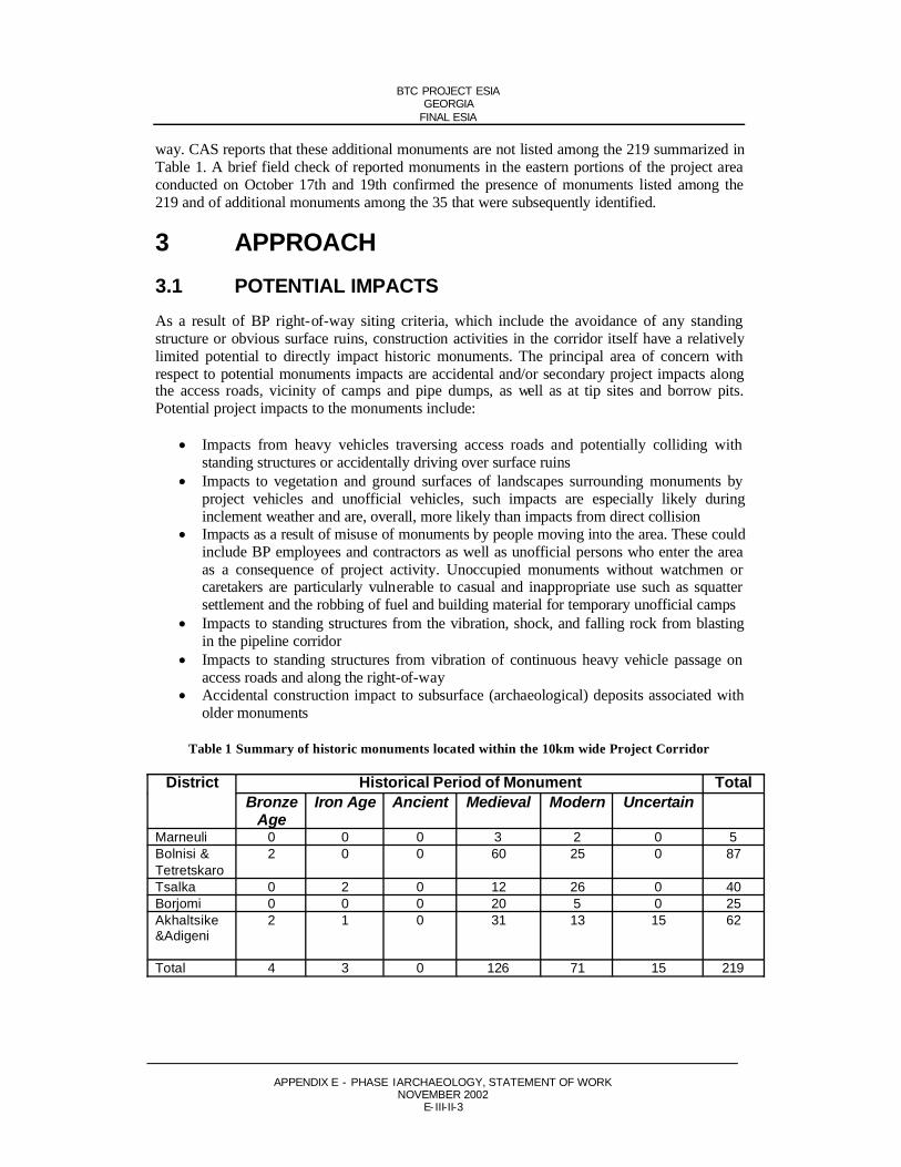
BTC PROJECT ESIAGEORGIA
FINAL ESIA
APPENDIX E - PHASE I ARCHAEOLOGY, STATEMENT OF WORKNOVEMBER 2002
E- III-II-3
way. CAS reports that these additional monuments are not listed among the 219 summarized in Table 1. A brief field check of reported monuments in the eastern portions of the project area conducted on October 17th and 19th confirmed the presence of monuments listed among the 219 and of additional monuments among the 35 that were subsequently identified.
3 APPROACH3.1 POTENTIAL IMPACTSAs a result of BP right-of-way siting criteria, which include the avoidance of any standing structure or obvious surface ruins, construction activities in the corridor itself have a relatively limited potential to directly impact historic monuments. The principal area of concern with respect to potential monuments impacts are accidental and/or secondary project impacts along the access roads, vicinity of camps and pipe dumps, as well as at tip sites and borrow pits. Potential project impacts to the monuments include:
Impacts from heavy vehicles traversing access roads and potentially colliding with standing structures or accidentally driving over surface ruins
Impacts to vegetation and ground surfaces of landscapes surrounding monuments by project vehicles and unofficial vehicles, such impacts are especially likely duringinclement weather and are, overall, more likely than impacts from direct collision
Impacts as a result of misuse of monuments by people moving into the area. These could include BP employees and contractors as well as unofficial persons who enter the area as a consequence of project activity. Unoccupied monuments without watchmen or caretakers are particularly vulnerable to casual and inappropriate use such as squatter settlement and the robbing of fuel and building material for temporary unofficial camps
Impacts to standing structures from the vibration, shock, and falling rock from blasting in the pipeline corridor
Impacts to standing structures from vibration of continuous heavy vehicle passage on access roads and along the right-of-way
Accidental construction impact to subsurface (archaeological) deposits associated with older monuments
Table 1 Summary of historic monuments located within the 10km wide Project Corridor
Historical Period of Monument TotalDistrictBronze
AgeIron Age Ancient Medieval Modern Uncertain
Marneuli 0 0 0 3 2 0 5Bolnisi & Tetretskaro
2 0 0 60 25 0 87
Tsalka 0 2 0 12 26 0 40Borjomi 0 0 0 20 5 0 25Akhaltsike&Adigeni
2 1 0 31 13 15 62
Total 4 3 0 126 71 15 219

BTC PROJECT ESIAGEORGIA
FINAL ESIA
APPENDIX E - PHASE I ARCHAEOLOGY, STATEMENT OF WORKNOVEMBER 2002
E- III-II-4
3.2 MITIGATION MEASURESPotential Mitigation Measures would include:
Placement of protective fencing and signs around vulnerable monument properties Including monuments protection guidance in HS&E communication to all employees
and contractors. Develop specific rules for contractors code of conduct Develop site specific evaluation and damage avoidance measures for monuments that
are vulnerable to vibration damage. These could include local vehicle speed and blasting restrictions. Restoration of fragile monuments and installation of ground-based or structural anti-vibration features would be last resort measures
Re-siting and/or partial re-routing of access routes to locations further away formmonuments
3.3 INVESTIGATION STRATEGYIdentification and potential evaluation of monuments normally required in order to establish and verify baseline resource conditions and to establish the likelihood of potential project impacts. Such studies typically involve three levels of study:
Desk and map survey to identify previously recorded monuments Reconnaissance level field survey to confirm the presence and location of previously
recorded or newly identified monuments Intensive level field survey to formally evaluate the importance and condition of
monuments
As mentioned, a literature based survey already conducted has indicated a substantial number of monuments in the project area. What is needed next is field reconnaissance in the project area to confirm and precisely locate monuments. BP will take the approach of doing reconnaissance in selected parts of the project area only, including areas in which substantial concentrations of monuments have been indicated by the literature search, and in the immediate vicinity of Camp and/or Pipedumps and associated access roads, ie those areas outside of the right-of-way that will receive most substantial project ground-disturbance. BP will assume that any apparent monument identified by desk study or field reconnaissance is significant. This approach saves project time and resources by avoiding the blanket application of intensive field survey level that is required for resource evaluation. Rather, intensive level survey is reserved for resources where a likely project impact to monuments is identified. Further, if likely impact mitigation measures are straightforward to implement, eg fencing and the posting of warning signs, then BP may choose to implement those measures without an intensive field investigation of the resource.
Field reconnaissance of areas not investigated in the this next phase of work could be conducted subsequently, as part of construction look-ahead work that would also, simultaneously, address surface apparent archaeological resources. A specific scope-of-work for that potentialinvestigation would be described in a subsequent document, which would benefit from the experience of the pre-construction heritage studies.

BTC PROJECT ESIAGEORGIA
FINAL ESIA
APPENDIX E - PHASE I ARCHAEOLOGY, STATEMENT OF WORKNOVEMBER 2002
E- III-II-5
4 SCOPE OF WORKThe above preconstruction monuments reconnaissance will be implemented with the following Tasks:
Task 1: Preparation of Draft Historic Context. This task will include brief review of project area maps and of readily available secondary historical and architectural-historical sources on the area. The purpose will be to establish a suitable periodizedhistoric narrative applicable to the project area. The narrative will include brief geographic description of the region, emphasizing past and present land-use,ethnic, and population patterns. This historic background will serve as a basis for predicting and understanding what types of monuments are likely to be present in the project area and what national historic themes may be of relevant to them. The draft context that results will be completed prior to the survey and later modified in content and emphasis based on the particular monuments that are identified during the field reconnaissance. The context will in its draft form emphasize monuments likely to be found in the specific survey areas indicated, namely along the access roads, and in the vic inity of camps and pipe dumps, as well as areas that the desk study indicated have the largest concentrations of monuments. The task will also include location and marking of survey areas on 1:10,000 and/or 1:5,000 scale topographic maps.
Task 2: Mobilization and Setup. This task addresses standard logistical and specific supply and equipment needs for the initiation of the monuments fieldreconnaissance. The task includes acquisition and packing of project vehicles with: field supplies and equipment, and archaeological supplies and equipment; Personal Protective Equipment; required first aid equipment, and other supplies. All required pre-field technical planning and technical briefing of crews by project seniortechnical staff will be carried out by this task. Senior staff of the field team will also review relevant literature reporting on previous investigations at the sites. All needed data collection procedures and forms will also be prepared and/or reviewed prior to departure for field. In sum, the task includes all preparatory activities required to initiate the fieldwork activities described in Task 3.
Beginning with Task 2 and continuing through the completion of Task 3, the field team will be subject to all normal BP consultant processes. For this project, these requirements will include, but not necessarily be limited to, the following:completion of BP land access process (including owner identification and owner compensation) for all fifteen sites to be investigated); BP logistics, planning and support process; BP security process; and BP HSE process.
In addition to the project technical report (Task 4), it will be the responsibility of the monuments field team to prepare weekly status reports, monthly reports,valuations, and any required change orders.
All participants in the fieldwork will obtain or show evidence of having BPapproved medical insurance prior to the start of fieldwork.
Task 3: Fieldwork . Proposed survey areas listed in Table 2 represent the proposed survey coverage for the monuments reconnaissance, which will be subject to review as part of Task 1. Fieldwork in the survey areas will include the following subtasks:

BTC PROJECT ESIAGEORGIA
FINAL ESIA
APPENDIX E - PHASE I ARCHAEOLOGY, STATEMENT OF WORKNOVEMBER 2002
E- III-II-6
Initial Monument Reconnaissance. This includes a combination of driving and walkover investigation of the access routes, pipe dumps, camp sites, as well as selected areas that have high concentrations of monuments, as indicated by the desk-based inventory and by the map review in Task 1. The purpose of the initial reconnaissance will be to identify presumed historic monuments within the survey areas for recording. Any above ground ruin or historic structure found within the survey areas that appear to have the potential for being a protected monument will be recorded.
Rough Monument Data Record. Presumed monuments identified will be annotated on topo maps, digitally photographed (2-4 photos), and quickly sketched in plan view. The sketch will be scaled by pacing rather than tape measure. Coordinates of the approximate centre of the monument property will be taken with GPS. A brief narrative description of the monument of not more than 50 words will be prepared, referencing apparent age, condition, type and size. Monument will be given a unique project resource number. Rough notes will be completed on single datedpage with the initials of individual making observations.
Photo Log. Photo log will be maintained in paper form corresponding to an MS-Excel spreadsheet version of photo log, in which all “paper form data” will be entered. Each photo will be given a unique code which will include the unique resource number of the corresponding monument. Photo log will also include date, name photographer, brief subject description, azimuth of photo orientation, and a free comment space.
Monument Report. Based on rough notes, photo designation, and coordinates, the required technical information will be entered in paper version of a monument report. The report will later be entered in an electronic record. A dual record of GPS points (on paper and in the electronic memory of instrument) will bemaintained for security. This data record will be the basic site data for each field recorded monument. The record will include data required for GIS Monument Data Record needed BP spatial constraints mapping. The latter will be prepared for loading in appropriate project GIS data layer. A draft of the Monument Report (suitable for monuments and archaeological sites) is presented in Appendix I of this proposal.

BTC PROJECT ESIAGEORGIA
FINAL ESIA
APPENDIX E - PHASE I ARCHAEOLOGY, STATEMENT OF WORKNOVEMBER 2002
E- III-II-7
Table 2 Proposed survey areas
Reconnaissance of all potential camp and/or pipedump sites including access roads:
1) Gardabani 1 Facility (Camp & Pipedump)2) Gardabani 2 Facility (Camp & Pipedump)3) Gatchiani Facility (Camp)4) Marneuli Facility (Camp)5) Kotishi Facility (Camp)6) Tetritskaro Facility (Pipedump)7) Tsalka 1 Facility (Camp & Pipedump)8) Tsalka 2 Facility (Camp & Pipedump)9) Andezit Facility (Pipedump)10) Tsikisjvari Facility/Concentration (Pipedump)11) Atskuri Facility/Concentration (Pipedump)12) Akhaltsike Facility (Camp & Pipedump)13) Vale Facility (Pipedump)14) TBD
Level of effort assumed for the fourteen sites eight crew days of fieldwork.(14 sites @ 3-4 per day + 2 days each for Tskisijvari & Atskuri= 8 days fieldwork):
Reconnaissance of five selected areas of monument concentration:
1) Mugiti-Samshildi concentration in Tetretskaro Region2) Santa-Bashtasheni concentration in Tsalka Region3) Avranlo-Kozil Kilisa Concentration in Tsalka Region4) Sadziri-Tadzsrisi concentration located between Tsikishvari and Atskuri5) Arali-Naokhrebi Concentration
Level of effort will be 20 crew days (5 concentrations @ 4 days each = 20 days fieldwork)
Survey Area Summary. Each survey area, whether Camp or Pipedump and Access Route, or monument concentration, will be summarized on a survey area summary sheet which delineates the survey zone spatially on the project topo map and summarizes the survey activities and findings within the zone. Photo of typical field conditions in the area will also be included in survey area report. Negative findings will be fully documented along with positive field findings.
Expedition Field Book. All daily activities will be recorded in single field journal entry. This will include date, field conditions, areas surveyed, monumentsidentified, field personnel participating in the work, and any special challenges or issues encountered during the day.
Electronic Text Record. All text notes taken in field, whether free text or formatted data will be electronically entered in word processing software in the field.
Task 4: Processing of Field Data. Crew will return from field to commence processing and write-up immediately.
Field Note Review. On return from the field all field forms and field notebooks will be reviewed for clarity and completeness. Field Sketches will be scanned and all electronic notes, photos and GPS coordinates will be backed up onto CD.

BTC PROJECT ESIAGEORGIA
FINAL ESIA
APPENDIX E - PHASE I ARCHAEOLOGY, STATEMENT OF WORKNOVEMBER 2002
E- III-II-8
Monument Reports. Standard report with one photograph on each site will be produced in electronic form, and in paper form for inclusion in the report.
Preparation of Monuments GIS Data Table . This standard subset of the heritage report data will be prepared in electronic form, and in paper format for inclusion in the report.
Mapping of Monuments. All monuments identified and recorded by thereconnaissance will be mapped on 1:100,000 project maps for inclusion in the report.
Task 5: Monuments Reconnaissance Report Preparation. Findings, tables, maps,Monument Reports and interpretations resulting from the previous tasks will be summarized and presented in a report following appropriate and customaryprocedures for reconnaissance level field recording of historic monuments.
The report should include the following or chapters and sections:
I. Abstract - Brief summary of salient report data including any recommendations for additional or contingent work (2-3 pages).
II. Introduction - Background data needed to understand report context, description of pipeline project, summary of study objectives, summary of report contents (1-2pages).
III. Regulatory Background - Description the National and Internationalrequirements (1-2 pages).
IV. Project Survey Area Description - Brief description of overall all geographic and environmental setting of pipeline indicating physiography geographic andpolitical features of over entire length of right of way. Specific areas surveyedshould be indicated as well. Include a small illustrative map of project area (2-3pages plus map).
V. Historic Context - Brief narrative overview of historical sequence as abackground for basic understanding of historic periods in which the differentmonuments in the project area. Emphasizing past cultural developments related to chronology and location of monuments identified. Draft context produced inTask 1 will be revised based on field findings (10 pages).
VI. Methodology – Description of field recordation technique with sample data collection form (2 pages).
VII. Fieldwork Description - Narrative description of work actually conducted at survey area with brief reference to findings. Including personnel involved.Schedule of work executed and any special conditions, special results, ordifficulties encountered. Will serve as description of scope of work executed (3-5).
VIII. Presentation of Site Findings - Summary of all monuments found organized by survey area and age of monument (3-5 pages).

BTC PROJECT ESIAGEORGIA
FINAL ESIA
APPENDIX E - PHASE I ARCHAEOLOGY, STATEMENT OF WORKNOVEMBER 2002
E- III-II-9
IX. Recommendations - Recommendations for future evaluation and protection work at each monument will be provided. Present generic description ofpreservation contingencies or mitigation measures recommended along with a list of monuments that may require such treatments (3-4 pages).
X. Bibliography.
XI. Appendices including: Monument Report for each site identified, table of GIS Heritage Data Records for monuments identified.
The above-described technical report along with all supporting data will bepresented to BP for review. Client comments will be addressed and the report finalized by the project team within two weeks of receipt of comments. Twoadditional copies of all rough notes, final report, and electronic data will be prepared and will become the property of CAS and the Department of Monuments protection.
Scoping assumptions
This scope of work is based on the key assumptions listed below:
a) All fieldwork and associated preparatory and support activity will be planned and executing following the HSE plan to be developed by the monuments team prior to award of contract.
b) It is understood that field reconnaissance will commence only when suitable weatherconditions allow. Early suspension of fieldwork, or the prospect of it, may require modifications in approach to the fieldwork.
c) Investigation of monuments identified along survey corridors should take an average of one hour per monument or Camp or Dump site, not including travel time. It is assumed that the field survey itself would require four weeks time.
d) The level effort for the monument team estimated to be as follows:
Task 1- Preparation of Draft Context (one week)Task 2- Mobilization and Setup (one week)Task 3- Fieldwork (five weeks)Task 4- Processing and Analysis (one week)Task 5- Report Writing (three weeks)Total Ten Weeks
e) For processing and analysis (Task 3) and reporting (Task 4) will depend in part on the number of monuments recorded. As a guideline, the basic processing and write-up time for one monuments specialist and one field assistant, excluding research for the draft context, would require approximately 1 week of effort for processing, 1 week for reporting, plus one day for each 20 monuments recorded. Assuming that 100monuments will be recorded, this would require approximately 4 weeks
f) The cost of purchase for existing 1:10,000 and 1:5,000 topographic maps covering each of the survey areas included in the proposal so that each archaeological field team

BTC PROJECT ESIAGEORGIA
FINAL ESIA
APPENDIX E - PHASE I ARCHAEOLOGY, STATEMENT OF WORKNOVEMBER 2002
E- III-II-10
conducting the work may add new data to the maps during investigation. Or, maps will be provided by BP at no cost to the contractor.
g) It is understood that the project sponsor will assist the field team by precisely locating the project survey areas. By providing maps and infield assistance from the land team.
h) It is understood that the survey area will consist of the planned location of all proposed or planned Camp and/or Dump Sites and associate access roads as well as monuments concentrations. The final selection of survey areas will be based on the best available at the start of the Monuments Reconnaissance Project.
5 SCHEDULEBased on the above task descriptions and assumptions, it is estimated that the entire Project will take 10 weeks to complete following notice to proceed.

BTC PROJECT ESIAGEORGIA
FINAL ESIA
APPENDIX E - PHASE I ARCHAEOLOGY, STATEMENT OF WORKNOVEMBER 2002
E- III-II-11
Appendix I
Proposed contents of monument report
1. Traditional Name of Monument:
2. Administrative Location of Monument:
3. Nearest BP Project Facility:
4. Easting:
5. Northing:
6. Reference Chainage:
7. Distance North or South of Reference Chainage:
8. Type of Monument:
9. Apparent Age of Monument:
10. Digital Photograph Reference:
11. Photo Title:
12. Photo:
13. Brief Monument Description:
14. Scanned Field Sketch:
15. Data Source:
BTC PROJECT ESIAGEORGIA
FINAL ESIA
APPENDIX E - PHASE I ARCHAEOLOGY, STATEMENT OF WORKNOVEMBER 2002
E- III-II-12
Appendix II
Draft data field list for heritage layer GIS record
Field 1: Site Number
Field 2: Site Description
Field 3: Map Symbol
Field 4: Arch./Mon./Both
Field 5: Data Source
Field 6: Northing
Field 7: Easting
Field 8: On Route Y/N
Field 9: On Route Y/N
Field 10: North or South of Route
Field 11: Comment


![ESIA - Services Architecture Enterprise Services Integrated Architecture [ESIA] Viv Noot PwC.](https://static.fdocuments.in/doc/165x107/56649e715503460f94b70588/esia-services-architecture-enterprise-services-integrated-architecture-esia.jpg)