Bailey DCS Connections - Products for Net 90&Infi 90 DCS · PDF fileThe Net 90 DCS and the...
29
Technical Manual Bailey DCS Connections November 2014 Previse
Transcript of Bailey DCS Connections - Products for Net 90&Infi 90 DCS · PDF fileThe Net 90 DCS and the...

Technical Manual
Bailey DCS Connections
November 2014
Previse

Prepared by:
Printed in Canada
This document is subject to continuous improvement, and as such is subject to change without notice. Feedback or inquiries regarding this document are welcome. Contact Previse via www.previse.com.
Proprietary Notice: This document and related software contain proprietary information which represents trade secrets of Previse Inc.® and may not be copied or disclosed, except as provided in the license with Previse Inc.
Use of the information in this document and related software, for the reverse engineering of OPsCon, or for the development or manufacture of similar software is prohibited. The information in this document is subject to change without notice and should not be construed as a commitment by Previse Inc. Previse Inc. assumes no responsibility for any errors that may be in this document.
Copyright 1999 - 2014 Previse Inc.® All rights reserved.
Unauthorized reproduction is a violation of Previse Inc. copyright.
Trademarks
Previse® is a trademark of Previse Inc.®
iFIX™ and iHistorian are registered trademarks of GE Fanuc.
Bailey,® Network 90,® Net 90® and INFI 90® are registered trademarks of Elsag Bailey Process Automation N.V.
Microsoft,® Windows NT,® and Microsoft SQL Server,™ are trademarks or registered trademarks of the Microsoft Corporation.
All other brand or product names are trademarks or registered trademarks of their respective holders.
Notice
Previse Inc.,® its partners, affiliates, employees, and agents, and the authors of, and contributors to, this publication and the software it represents, specifically disclaim all liabilities and warranties, express and implied (including warranties of merchantability and fitness for a particular purpose), for the accuracy, currency, completeness, and/or reliability of the information contained herein, and/or for the fitness for any particular use, and/or for the performance of any material, and/or for equipment selected in whole or part by the user in reliance upon information contained herein. Selection of materials and/or equipment is at the sole risk of the user of this publication.
Previse Inc.® Managing Critical Microsoft® Technology

Technical Manual – Supported Bailey DCS Connections
Copyright 1999-2014 Previse Inc. All Rights Reserved. ii
Table of Contents 1 Introduction............................................................................................................1
2 Bailey DCS Overview .............................................................................................1
3 Supported Connections to Bailey DCS ..................................................................2
4 CIC01 Connection ..................................................................................................3
5 NCIU01 Connection ...............................................................................................4
6 NCIU02 Connection ...............................................................................................5
7 NCIU03 Connection ...............................................................................................7
8 NCIU04 Connection ...............................................................................................9
9 INICI01 / INICT01 Connection ...........................................................................11
10 INPCI02 Connection .......................................................................................13
11 IIMCP01 / IIMCP02 Connection....................................................................15
12 INICI03 / INICT03 Connection ......................................................................19
13 INICI13 / INICT13 Connection ......................................................................22
14 INICI12 / INICT12 Connection ......................................................................25

Technical Manual – Supported Bailey DCS Connections
Copyright 1999-2014 Previse Inc. All Rights Reserved. 1
Supported Bailey DCS Connections
1 Introduction
This manual provides technical information required for the physical connection
of the Previse OPC Server/Driver to the Bailey Net 90 or INFI 90 DCS.
This manual includes:
• Instructions for module set up for communications with Driver.
• Description of known communications limitations where applicable
This manual does not include:
• Instructions for installation or general configuration of modules.
Previse OPC Server & Driver for Bailey DCS
Previse offers a Driver, which also functions as an OPC Server, for connection to Bailey DCS Systems. This product is sold in several different configurations, and this manual applies to all of them. In this manual, this Previse OPC Server/Driver is simply referred to as the Driver.
2 Bailey DCS Overview
The Net 90 DCS and the INFI 90 DCS are products of Elsag Bailey Process Automation N.V., now ABB, and are marketed and installed worldwide.
Net 90 and INFI 90
The Net 90 DCS, introduced in the 1980, and the INFI 90 DCS, introduced in the 1988, are widely used for process control in process oriented plants, in industries such as pulp and paper, power generation, cement making, glass, chemical and many others. In these industries the Bailey DCS system are respected for the high level of process automation reliability that they bring.
Data Highways
All DCS systems on the marketplace rely on a “data highway” for high speed data communications between all of the distributed components of the DCS system. Over the life of the Net 90 and INFI 90 product lines, three primary
data highways have been used: Plant Loop , Super Loop and INFI Net.
Connecting to Bailey DCS
The Driver may be connected to any Bailey DCS via a gateway device, variously called a Computer Interface Unit (CIU), an INFI-NET to Computer Interface (ICI) or a Plant Loop to Computer Interface (PCI). These interfaces, designed for connection of external devices to the Bailey DCS, allow the OPC Data Server to communicate with the Bailey DCS modules.

Technical Manual – Supported Bailey DCS Connections
Copyright 1999-2014 Previse Inc. All Rights Reserved. 2
3 Supported Connections to Bailey DCS
The table below lists all of the Bailey DCS connections that are supported by the Driver. Further details regarding each of the supported connections may be found in the following sections within this appendix.
Support for communications to additional devices may be added. If you need support for devices not mentioned here, please contact us.
Supported Bailey DCS Connections
Bailey DCS Data Highway
Connection
Method Net
90
INFI
90
Plant
Loop
Super
Loop
INFI
Net
Support
Ref.
Section
CIC011 YES 4
NCIU01 X X YES2 5
NCIU02 X X YES 6
NCIU03 X X YES 7
NCIU04 X X X X YES 8
INICI01/INICT01 X X X YES 9
INPCI02 X X YES 10
INMCP01 X X X X X YES 11
INMCP02 X X X YES3 11
INICI03/INICT03 X X YES4 12
INICI13/INICT13 X X YES 13
INICI12/INICT12 X X X X X YES 14
INPCI01 X X YES5 -
IMCPM01/02/03 NO
1 This Loop Command Series product provides a connection to Bailey Module Bus rather than to data highway 2 CIU01 data acquisition functions are supported. There are limitations for STATION type tags. 3 INMCP02 support includes serial & SCSI communications. Previse SCSI hardware kit required for SCSI communications. 4 INICI03/INICT03 support includes serial & SCSI communications. Previse SCSI hardware kit required for SCSI communications. Section 13 provides details of supported firmware versions. 5 INPCI01 communications have not been tested, but we believe all required support is present. If INPCI01 communications are required, please call for assistance.

Technical Manual – Supported Bailey DCS Connections
Copyright 1999-2014 Previse Inc. All Rights Reserved. 3
4 CIC01 Connection
Overview
Overview Details of CIC01 Module Supported Connections Supports connection to Plant Loop in Bailey Network 90 DCS.
Maximum Point Capacity CIC01 supports to 500 Bailey Tags maximum. Driver supports 30,000 Tags and can support simultaneous multiple CIC01 connections.
Bailey Document References Bailey Instruction Manual E92-504-2
Module Overview
The CIC01 is a standalone communications module. It serves as an inexpensive communications link between the Driver and the Module Bus within the Bailey DCS.
Cabling to CIC01
The Driver is connected to the CIC01 using a serial RS-232 communication channel. Cables are not provided. Connect the serial RS-232 cable to the 9 pin D RS-232 connector. The wiring of the connector is defined in the CIC01 instruction manual E92-504-2. Connect the serial cable to the selected COM port of the computer containing the Driver.
CIC01 Switch Settings
CIC01 Switch Settings S1-1 - Closed Enables checksum of command reply
S1-2 - Open
S1-3 - Open
Selects 9600 baud, the maximum rate available with CIC01
S1-4 - Closed
S1-5 - Closed
Selects 8 data bits, 1 stop bit, no parity
S1-6
S1-7
n/a
Switch
Settings
for CIC01
S1-8 Open selects module address of 1; Closed selects default address of 0

Technical Manual – Supported Bailey DCS Connections
Copyright 1999-2014 Previse Inc. All Rights Reserved. 4
5 NCIU01 Connection
The Driver supports all data acquisition functions of the NCIU01, but has limitations with respect to STATION tag types. Please call for details.
Overview
NCIU01 Overview Supported Connections Supports connection to Plant Loop in Bailey Network 90 DCS.
Maximum Point Capacity NCIU01 supports to 511 Bailey tags. Driver supports to 30,000
tags and can support multiple simultaneous NCIU01 connections
Module Structure
The NCIU01 consists of the following three modules:
• NLIM02 (Loop Interface Module - LIM)
• NPTM01 (Point Table Module - PTM)
• NSIM01 (Serial Interface Module - SIM).
The LIM, PTM and SIM modules reside in a dedicated module mounting unit chassis (MMU). The PTM is connected to the LIM via a direct-memory-access ribbon cable. The PTM stores data then transfers it to the SIM for sending to the Driver. The three modules form a Plant Loop node.
The NSIM01 is connected to a NTCU01 termination unit that provides two RS232 serial ports. The Driver connects to one of these serial ports, communicating at a rate of up to 19,200 Baud.
Cabling to NCIU01
The Driver is connected to the NCIU01 using a serial RS-232 communication channel. Cables are not provided. Connect the serial RS-232 cable to the 25 pin D connector labeled ‘‘Terminal”. The wiring of the connector is defined in the CIU driver’s instruction manual. At the computer containing the driver, connect the serial cable to the COM port.
CIU01 Settings
NCIU01 Settings Dip shunt Straps for TMF or IMF Note: 0=Cut (OPEN), 1=Intact (CLOSED)
XU1 – 1110011010
XU2 – 0010100000

Technical Manual – Supported Bailey DCS Connections
Copyright 1999-2014 Previse Inc. All Rights Reserved. 5
6 NCIU02 Connection
Overview
NCIU02 Overview Supported Connections Supports connection to Plant Loop in Bailey Network 90 DCS.
Maximum Point Capacity NCIU02 supports to 2500 Bailey Tags. Driver supports to 30,000 Tags
Bailey Document References Bailey Instruction Manual E93-905-9
Enhanced Computer Interface Unit Programmer’s Reference Manual
INFI-Net Communications Modules E96-601
Bailey Instruction Manual E93-905-2.
Module Structure
The NCIU02 consists of following three modules:
• NLIM02 (Loop Interface Module)
• NBTM01 (Bus Transfer Module)
• NLSM01 (Loop Storage Module)
The BTM is connected to the LIM with a direct-memory-access ribbon cable. The two modules work together as one. The BTM transfers data from the Plant Loop to the LSM where it is held until required by the Driver. The three modules form a node on the Plant Loop.
The NLSM01 is connected to a NTMF01 termination unit that provides two RS232 serial ports. The Driver connects to one of these serial ports, communicating at 19,200 Baud.
IEEE488 Parallel Bus
The NCIU02 can optionally contain an NPBS01 (Parallel Bus Slave module). This module takes a single slot. The PBS provides an IEEE-488 parallel bus for communication with the loop storage module. The module can transfer bursts of data over the IEEE-488 bus at 240K bytes/second. The communication transfer rate to the LSM is limited to 80,000 bytes/second by the expander bus capability.
The Driver does not support IEEE-488 communications.

Technical Manual – Supported Bailey DCS Connections
Copyright 1999-2014 Previse Inc. All Rights Reserved. 6
Cabling to NCIU02
The Driver is connected to the NCIU02 using a serial RS-232 communication channel. The required cables are not provided.
At the NCIU02:
Connect the serial RS-232 cable to the 25 pin D connector labeled ‘‘Terminal”. The wiring of the connector is defined in the CIU driver’s instruction manual.
At the Driver:
Connect the serial cable to the selected COM port.
NCIU02 Settings
NCIU02 Settings DIP Switch Settings for LSM Note: 0=Closed (ON), 1=Open(OFF)
U72 – 00010010
U73 – 11111111
U75 – 00000
DIP Switch Settings for LIM Note: 0=Closed (ON), 1=Open(OFF)
SW1 – 00110000
SW2 – Bailey Node Address
DIP Switch Settings for BTM Note: 0=Closed (ON), 1=Open(OFF)
SW1 - 00000
Dip shunt Straps for TMF or IMF Note: 0=Cut (OPEN), 1=Intact (CLOSED)
XU1 – 1110011010
XU2 – 0010100000

Technical Manual – Supported Bailey DCS Connections
Copyright 1999-2014 Previse Inc. All Rights Reserved. 7
7 NCIU03 Connection
Overview
NCIU03 Overview Supported Connections Supports connection to Plant Loop in Bailey Network 90 DCS.
Maximum Point Capacity NCIU03 supports to 5,000 Tags. Driver can support to 30,000 Tags
Bailey Document
References
Bailey Instruction Manual E93-905-9: Enhanced Computer
Interface Unit Programmer’s Reference Manual
Bailey Instruction Manual E93-905-2.
Module Structure
The NCIU03 consists of the following three modules:
• NLIM02 (Loop Interface Module)
• NBTM01 (Bus Transfer Module)
• NLSM02 (Loop Storage Module).
The BTM is connected to the LIM via a direct-memory-access ribbon cable. The two modules work together as one. The BTM transfers data from the Plant Loop to the LSM where it is held until required by the Driver node. The three modules form a node on the Plant Loop. Figure 4 illustrates the structure of the NCIU03.
The NLSM02 is connected to a NTMF01 termination unit that provides two RS232 serial ports.
Optional IEEE488 Parallel Bus
The NCIU03 can optionally contain an NPBS01 (Parallel Bus Slave module). This module takes a single slot. The PBS provides an IEEE-488 parallel bus for communication with the loop storage module. The module can transfer bursts of data over the IEEE-488 bus at 240K bytes/second. The communication transfer rate to the LSM is limited to 80,000 bytes/second by the expander bus capability.
Driver does not support IEEE-488 communications..

Technical Manual – Supported Bailey DCS Connections
Copyright 1999-2014 Previse Inc. All Rights Reserved. 8
Cabling to NCIU03
The Driver is connected to the NCIU03 using a serial RS-232 communication channel. The required cables are not provided.
At the NCIU03:
Connect the serial RS-232 cable to the 25 pin D connector labeled ‘‘Terminal”. The wiring of the connector is defined in the CIU driver’s instruction manual.
At the Driver:
Connect the serial cable to the selected COM port.
NCIU03 Setup
NCIU03 Setup DIP Switch Settings for LSM Note: 0=Closed (ON), 1=Open(OFF)
U72 – 00010010 U73 – 11111111 U75 – 00000
DIP Switch Settings for LIM Note: 0=Closed (ON), 1=Open(OFF)
SW1 – 00110000
SW2 – Bailey Node Address
DIP Switch Settings for BTM Note: 0=Closed (ON), 1=Open(OFF)
SW1 – 00000
Dip shunt Straps for TMF or IMF Note: 0=Cut (OPEN), 1=Intact (CLOSED)
XU1 – 1110011010
XU2 – 0010100000

Technical Manual – Supported Bailey DCS Connections
Copyright 1999-2014 Previse Inc. All Rights Reserved. 9
8 NCIU04 Connection
Overview
NCIU04 Overview Supported Connections Supports connection to the Super Loop in Bailey Network 90 DCS.
Maximum Tag Capacity NCIU04 supports to 10,000 tags. Driver supports up to 30,000 tags
Bailey Document
References
Bailey Instruction Manual E93-905-9: Enhanced Computer Interface Unit Programmer’s Reference Manual
INFI-Net to Plant Loop Gateway (INIPL01) manual E96-602
Module Structure
The NCIU04 is based on the Network 90 architecture. It uses the module bus for back plane communication. It consists of the following two modules:
• NLIS01 (Loop Interface Slave module)
• NSSM01 (Super Loop Storage Module)
The NSSM01 occupies two slots. The NLIS01 is a slave module to the NSSM01, which acts as a bus master module. The SSM module communicates to the LIS module over the expander bus. These two modules form a Super Loop node.
The NSSM01 is connected to a NTMF01 termination unit that provides two RS232 serial ports. Driver connects to one of these serial ports, communicating at 19, 200 Baud.

Technical Manual – Supported Bailey DCS Connections
Copyright 1999-2014 Previse Inc. All Rights Reserved. 10
Cabling to NCIU04
The Driver is connected to the NCIU04 using a serial RS-232 communication channel. The required cables are not provided.
At the NCIU04:
Connect the serial RS-232 cable to the 25 pin D connector labeled ‘‘Terminal.” The wiring of the connector is defined in the CIU driver’s instruction manual.
At the Driver:
Connect the serial cable to the selected COM port.
NCIU04 Setup
NCIU04 Setup DIP Switch Settings for SSM Note: 0=Closed (ON), 1=Open(OFF)
U72 – 00010010
U73 – 11111111
U75 – 00000
DIP Switch Settings for LIS Note: 0=Closed (ON), 1=Open(OFF)
SW1 – Bailey Loop Address
SW2 – Bailey Node Address
SW3 – 01001000 (Set for 10MB Super Loop)
SW4 – 00010000
Jumper Settings per Silk Screen on Module
Dip shunt Straps for TMF or
IMF
Note: 0=Cut (OPEN), 1=Intact (CLOSED)
XU1 – 1110011010
XU2 – 0010100000
Technical Manual – Supported Bailey DCS Connections
Copyright 1999-2014 Previse Inc. All Rights Reserved. 11
9 INICI01 / INICT01 Connection
Overview
INICI01 Overview Supported Connections INFI-Net and the Super Loop in Bailey INFI 90 DCS.
Maximum Tag Capacity ICI01 supports to 10,000 tags. Driver can support to 30,000 tags
Bailey Document
References
Bailey Instruction Manual E93-905-9: Enhanced Computer Interface
Unit Programmer’s Reference Manual
Manual E96-501D.
Manual E96-610A.
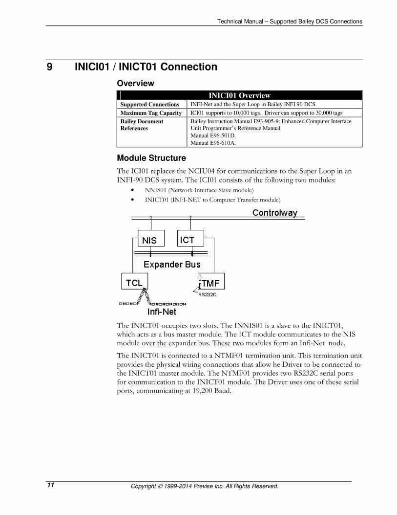
Module Structure
The ICI01 replaces the NCIU04 for communications to the Super Loop in an INFI-90 DCS system. The ICI01 consists of the following two modules:
• NNIS01 (Network Interface Slave module)
• INICT01 (INFI-NET to Computer Transfer module)
The INICT01 occupies two slots. The INNIS01 is a slave to the INICT01, which acts as a bus master module. The ICT module communicates to the NIS module over the expander bus. These two modules form an Infi-Net node.
The INICT01 is connected to a NTMF01 termination unit. This termination unit provides the physical wiring connections that allow he Driver to be connected to the INICT01 master module. The NTMF01 provides two RS232C serial ports for communication to the INICT01 module. The Driver uses one of these serial ports, communicating at 19,200 Baud.

Technical Manual – Supported Bailey DCS Connections
Copyright 1999-2014 Previse Inc. All Rights Reserved. 12
Cabling to ICI01
The Driver is connected to the ICI01 using a serial RS-232 communication channel. The required cables are not provided.
At the ICI01:
Connect the serial RS-232 cable to the 25 pin D connector labeled ‘‘Terminal”. The wiring of the connector is defined in the CIU instruction manual.
At the Driver:
Connect the serial cable to the selected COM port.
INICI01 Component Setup
INICI01 Component Setup DIP Switch Settings for ICT01 Note: 0=Closed (ON), 1=Open(OFF)
U72 – 00010010 U73 – 11111111 U75 – 00000
DIP Switch Settings for NIS01 Note: 0=Closed (ON), 1=Open(OFF)
SW1 – Bailey Loop Address
SW2 – Bailey Node Address
SW3 – 01001000 (Set for 10MB Super Loop)
SW4 – 00010000
Jumper Settings per Silk Screen on Module
Dip shunt Straps for TMF or
IMF
Note: 0=Cut (OPEN), 1=Intact (CLOSED)
XU1 – 1110011010
XU2 – 0010100000

Technical Manual – Supported Bailey DCS Connections
Copyright 1999-2014 Previse Inc. All Rights Reserved. 13
10 INPCI02 Connection
Overview
INPCI02 Overview Supported Connections Plant Loop in Bailey Net 90 DCS.
Maximum Tag Capacity INPCI02 supports to 5,000 tags. Driver support to 30,000 Tags
Bailey Document
0References
Bailey Instruction Manual E93-905-9: Enhanced Computer Interface
Unit Programmer’s Reference Manual
Manual E96-501D.
Manual E96-610A.
Controller Modules
Supported
Driver supports Function Code data communications to the following controller modules: MFP01; MFP02; MFP03; MFC01; MFC02; MFC03; MFC04; MFC05 ;COM01; COM 02; COM03; COM04; LMM01; LMM02; RIO01; RIO02
Module Structure
The INPCI02 consists of three modules:
• INLIM03 (Loop Interface Module)
• INBTM01 (Bus Transfer Module)
• INPCT01 (Plant Loop to Computer Transfer module)
The bus transfer module communicates with the loop interface module through a direct memory access ribbon cable. The bus transfer module transfers the data from the plant loop to the computer transfer module. The computer transfer module responds to commands from the Driver and delivers the data requested.
The PCT provides two RS232C communication channels for communication. These channels are similar to those provided by its predecessor, the CIU.

Technical Manual – Supported Bailey DCS Connections
Copyright 1999-2014 Previse Inc. All Rights Reserved. 14
Cabling to INPCI02
The Driver is connected to the INPCI02 using a serial RS-232 communication channel. The required cables are not provided.
At the INPCI02:
Connect the serial RS-232 cable to the 25 pin D connector labeled ‘‘Terminal”. The wiring of the connector is defined in the CIU driver’s instruction manual.
At the Driver:
Connect the serial cable to the selected COM port.
INPCI01 Setup
INPCI02 Setup DIP Switch Settings for
PCT
Note: 0=Closed (ON), 1=Open(OFF)
U72 – 00010010
U73 – 11111111
U75 – 00000
DIP Switch Settings for
LIM
Note: 0=Closed (ON), 1=Open(OFF)
SW1 – 00110000
SW2 – Bailey Node Address
DIP Switch Settings for
BTM
Note: 0=Closed (ON), 1=Open(OFF)
SW1 - 00000
Dip shunt Straps for
TMF or IMF
Note: 0=Cut (OPEN), 1=Intact (CLOSED)
XU1 – 1110011010
XU2 – 0010100000

Technical Manual – Supported Bailey DCS Connections
Copyright 1999-2014 Previse Inc. All Rights Reserved. 15
11 IIMCP01 / IIMCP02 Connection
Overview
IIMCP01/02 Overview Supported Connections IIMCP01: Plant Loop
IIMCP02: INFI-Net and the Super Loop in INFI 90
Maximum Point
Capacity
IIMCP01/02 supports to 10,000/30,000 tags. Driver supports to 30,000 tags
Bailey Instruction Manual E93-905-9: Enhanced Computer Interface Unit Programmer’s Reference Manual
Manual E96-501D.
Manual E96-610A.
Bailey Document
References
Operator Interface Station (40 Series) Hardware manual
Module Structure
The CIU type interface consists of three modules:
• IIMLM0l multi-bus loop module
• IIMCP0l/02 multi-bus communication processor module
• IIMCL01 loop termination module
The IIMLM0l multi-bus loop module, allows communication between the multi-bus communication processor module (IIMCP0l or IIMCP02) and the INFI-NET or Plant Loop communication highway through the termination module (IIMCL01).
Two ribbon cables connect the loop module to the communication processor module and to the communication loop module terminations. Dipswitches SW1 and SW2 select the node address and ring number of the console.
An IIMKM02 keyboard interface or an IIMRM02 reset module is present in the multi-bus card cage. The modules provide power-up reset signal and power fault interrupt on the multi-bus back-plane.

Technical Manual – Supported Bailey DCS Connections
Copyright 1999-2014 Previse Inc. All Rights Reserved. 16
Cabling for Serial Communications (IIMCP01 & IIMCP02)
The Driver is connected to the IIMCP02 via serial RS-232.
At the IIMCP01/02:
For serial connect the RS-232 cable to the 9 pin D connector labeled PORT-B. Standard 9 pin RS232 cables can be used (not provided). IIMCP01/02 DIP switch settings must be correct.
At the Driver:
Connect the serial cable to the selected COM port.
Cabling for SCSI Communications (IIMCP02)
A SCSI Connection Kit containing the required cables, certified SCSI interface adapter and terminators must be purchased from Previse (or your supplier). This kit contains:
a) SCSI Adapter for connect to PC computer6
b) SCSI connector to connect to IIMCP02/INICT03 SCSI connector
c) All cables & connectors required to connect between (a) and (b) above7
d) Appropriate SCSI termination hardware8
e) Installation instructions
� NOTE: The SCSI standard employed is an old 8 bit SCSI-1 standard. Maintenance of warranty requires purchase of SCSI kit mentioned above.
At the IIMCP02:
Connect the standard 50 pin flat cable connector to IIMCP02 connector P7. Appropriate SCSI termination hardware, provided in the kit, must be installed according to the accompanying instructions.
At the Driver:
Install the provided SCSI adapter and connect the SCSI cable provided in the kit to the connector on the SCSI adapter.
� NOTE: The SCSI channel used for DCS communications must be a dedicated SCSI channel with no other devices on the same SCSI Adapter.
6 Previse offers a SCSI Adapter kit suitable for installation in a 5 volt PCI card slot. It is expected that additional options will be required for installation in 3.5 volt PCIX card slot and via USB port. Contact us if you require this. 7 The recommended SCSI cable length is limited to 6 feet (1.8 meters). 8 SCSI termination will include one or more of (a) SCSI terminator connector to install in connector P8, or (b) SIP resistors may need to be inserted in IIMCP02 connectors labeled RN2, RN3 and RN4 or (c) SCSI cable may have a build in terminator.

Technical Manual – Supported Bailey DCS Connections
Copyright 1999-2014 Previse Inc. All Rights Reserved. 17
IIMCP01 Setup
IIMLM01 DIP Switch Description
Switch Position Description Switch Settings / Range 1 1-8 Node / PCU 1 - FA (hex pole 8 LSB)
2 1-8 Ring / Loop 1 - FA (hex pole 8 LSB)
0 = MCP 1 Device Compatibility
1 = BCM
0 = No checksum 2 ROM checksum
1 = Checksum Enabled
0 = Normal Operation 3 RUN mode
1 = Test mode
0 = Normal Operations 4 Busy Test
1 = Busy NAK all loop messages if
RUN mode is Test
0 = Disable LED’s flashing 5 Broken Loop Indication
1 = Flashing LED’s
0 = Normal Operations 6 Diagnostic Enabled
1 = Diagnostic enabled
00 = 10 MHz INFI-NET
01 = 2 MHz INFI-NET
10 = Do not use
3
7-8 Loop Type
11 = Plant Loop
1-3 I/O expander bus
address select
0 – 7 4
4-8 LED display select 0 – 1F (hex)
NOTE: O = CLOSED or ON, 1 = OPEN or OFF. Bold areas indicate factory default settings.
Use factory settings, or settings to match DCS configuration, to set up IIMLM01.
IIMCP01 DIP Switch Description
Switch Position Description Switch Settings / Range
Configure the IIMCP01 module by setting dipswitches. Also located on the module board
are jumpers J5. J6. and J7. Jumper J5 should not be changed from the factory setting. 0 = No checksum 1 ROM checksum
1 = Checksum Enabled
00 = 8 d ,1s, no parity
01 = 8 d, 1s, even parity
10 = 8 d, 1s, odd parity
2-3 Port A Parity settings
11 = 8 d, 1s, no parity
0 = NIU command mode 4 Port B Mode
1 = NIU utility mode
00 = 8 d ,1s, no parity
01 = 8 d, 1s, even parity
10 = 8 d, 1s, odd parity
5-6 Port B Parity settings
11 = 8 d, 1s, no parity
0 = No checksum
0
7 Command checksum
1 = Checksum Enabled
1-4 Port A baud rate 1111 = 19200, 0111 = 9600 1
5-8 Port B baud rate 1111 = 19200, 0111 = 9600
0 = Test mode 1 Firmware test mode
1 = Normal Operation
0 = Disabled 2 Diagnostic mode
1 = enabled
0 = Disabled 3 INFI-NET system
diagnostic mode 1 = enabled
4-6 Not used -
7 NVRAM 1 = enabled, 0 = disabled
2
8 RAM Size 1, 0
NOTE: O = CLOSED or ON, 1 = OPEN or OFF. Bold areas indicate factory default settings.

Technical Manual – Supported Bailey DCS Connections
Copyright 1999-2014 Previse Inc. All Rights Reserved. 18
IIMCP02 DIP Switch Description
Switch Position Description Switch Settings / Range 1-4 Port A baud rate 1111 = 19200, 0111 = 9600 1
5-8 Port B baud rate 1111 = 19200, 0111 = 9600
0 = Enabled 1 MLM handshake timeout
1 = Disabled
0 = Disabled 2 MLM Diagnostic mode
1 = Enabled
0 = Disabled 3 Diagnostic utilities mode
1 = Enabled
0 = Disabled 4 Hardware diagnostics
1 = Enabled
2
5-8 Not used -
0 = Disabled 1 SCSI port
1 = Enabled
2-4 SCSI address 100 = 4
0 = Disabled 5 SCSI parity check enabled
1 = Enabled
3
6-8 Not used -
0 = Enabled 4 1 ROM checksum
1 = Disabled
00 = 8 d ,1s, no parity
01 = 8 d, 1s, even parity
10 = 8 d, 1s, odd parity
2-3 Serial Port Parity settings
11 = 8 d, 1s, no parity
0 = NIU command mode 4 Serial Port B Mode
1 = NIU utility mode
0 = Disabled 5 Modem Password
protection 1 = enabled
0 = Disabled 6 Port addressing mode
1 = enabled
0 = Disabled 7 Command checksum
1 = Enabled
1 = Security Enabled 8 Security ENABLE
MCP02 only 0 = Security Disabled
NOTE: O = CLOSED or ON, 1 = OPEN or OFF. Bold areas indicate factory default settings.
IIMCP02 Default Jumper Settings J1 J2 J5,J6 J7 J8 J9 J10,J11 1-3 1-4 1-2 1-2 1-2 3-4 1-2
2-4 3-4
5-7 5-6
6-8 7-8
Default jumper settings should not be changed for standard applications.
IIMCP01 DIP Switch Settings for Serial Communications DIP Switch 0 LSB 1101xx1x MSB
DIP Switch 1 LSB 1111xxxx MSB
DIP Switch 2 LSB 100xxx11 MSB
IIMCP02 DIP Switch Settings for Serial Communications DIP Switch 1 LSB 11111111 MSB
DIP Switch 2 LSB 00000000 MSB
DIP Switch 3 LSB 01000000 MSB
DIP Switch 4 LSB 00000010 MSB
IIMCP02 DIP Switch Settings for SCSI Communications DIP Switch 1 LSB 11111111 MSB
DIP Switch 2 LSB 00000000 MSB
DIP Switch 3 LSB 11001000 MSB
DIP Switch 4 LSB 00010010 MSB

Technical Manual – Supported Bailey DCS Connections
Copyright 1999-2014 Previse Inc. All Rights Reserved. 19
12 INICI03 / INICT03 Connection
Overview
INICI03 / INICT03 Overview Supported Connections INFI-Net and the Super Loop in Bailey INFI 90 DCS.
Maximum Tag Capacity INICI03 supports to 30,000 tags. Driver supports to 30,000 tags
Bailey Document
References
Bailey Instruction Manual E93-905-9: Enhanced Computer Interface
Unit Programmer’s Reference Manual
Manual E96-501D.
Manual E96-610A.
Module Structure
The ICI03 consists of the following modules:
• INNIS01 (Network Interface Slave module)
• INICT03 (INFI-NET to Computer Transfer module)
• IMMPI01 – SCSI and serial interface
• NKTI|U01 cable
• NTPM01 terminator
The INICT03 occupies two slots. The INNIS01 is a slave to the INICT03, which acts as a bus master module. The ICT03 communicates to the NIS over the expander bus. These two modules form a node on the INFI-NET.
The INICT03 is connected to a NTPM01 termination unit. This termination unit provides the physical wiring connections that allow the Driver to be connected to the INICT03 master module. The NTPM01 provides two RS232C serial ports for communication to the INICT03 module. The Driver can use one of these serial ports, communicating at 19,200 Baud.
The INICT03 is designed with a SCSI interface. This interface is the preferred connection to the host computer and should be used in most applications.
Cabling for Serial Communications to INICT03
At the INICT03:
Connect the serial RS-232 cable to the 25 pin D connector labeled ‘‘Printer”. The wiring of the connector is defined in the CIU driver’s instruction manual.
At the Driver:
Connect the serial cable to the selected COM port.

Technical Manual – Supported Bailey DCS Connections
Copyright 1999-2014 Previse Inc. All Rights Reserved. 20
Cabling for SCSI Communications to INICT03
A SCSI Connection Kit containing the required cables and certified SCSI interface adapter must be purchased from Previse (or your supplier). This kit contains:
• SCSI Adapter for connect to PC computer (PCI or PCI-X or PCI Express card slot)9
• Cable required to connect between SCSI adapter and INICI0310
• Installation instructions
� NOTE: The SCSI standard employed is an old 8 bit SCSI-1 standard. Maintenance of warranty requires purchase of SCSI kit mentioned above.
At the INICT03:
Connect the standard 50 pin flat cable connector to IMMPI01. Appropriate SCSI termination hardware, provided in the kit, must be installed according to the accompanying instructions.
At the Driver:
Install the provided SCSI adapter and connect the SCSI cable provided within the SCSI kit to the connector on the SCSI adapter.
� NOTE: The SCSI channel used for DCS communications must be a dedicated SCSI channel with no other devices on the same SCSI Adapter.
NIS and TMF Setup
Configure INNIS01 per instructions in ABB Instruction Manual. Must be configured correctly for your specific DCS configuration.
INICT03 Firmware Version Considerations
There is a set of versioned EPROM firmware installed on the INICT03. Driver support for this firmware is as follows:
Firmware Version Supported?
Versions prior to E0 Supported
E0 Supported
F0, F1 Not Supported – Hardware dongle required.
G0 and later Supported
9 Previse offers a SCSI Adapter kit, consisting of SCSI adapter card and SCSI cable. To order you must specify (a) whether the SCSI adapter card must insert into PCI or PCI-X or PCI Express card slot within the PC and (b) 6, 8, 10, pr 12 feet cable length. It is your responsibility to ensure this is correctly specified to Previse. 10 The SCSI cable length, between impedance termination at either end, MUST not exceed 6 meters (19 feet). Recommended SCSI cable length is 6, 8, 10 or 12 feet, provided that overall length between terminations < 6 meters maintained .

Technical Manual – Supported Bailey DCS Connections
Copyright 1999-2014 Previse Inc. All Rights Reserved. 21
INICT03 DIP Switch Description
INICT03 DIP Switch Description
Switch Position Description Switch Settings / Range 1-4 Port A baud rate 1111 = 19200, 0111 = 9600 1
5-8 Port B baud rate 1111 = 19200, 0111 = 9600
0 = Enabled 1 MLM handshake
timeout 1 = Disabled
0 = Disabled 2 MLM Diagnostic mode
1 = Enabled
0 = Disabled 3 Diagnostic utilities
mode 1 = Enabled
0 = Disabled 4 Hardware diagnostics
1 = Enabled
2
5-7 Not used -
0 = Disabled 1 SCSI port
1 = Enabled
2-4 SCSI address 100 = 4
0 = Disabled 5 SCSI parity check
enabled 1 = Enabled
3
6-8 Not used -
0 = Enabled 4 1 ROM checksum
1 = Disabled
00 = 8 d ,1s, no parity
01 = 8 d, 1s, even parity
10 = 8 d, 1s, odd parity
2-3 Serial Port Parity
settings
11 = 8 d, 1s, no parity
0 = NIU command mode 4 Serial Port B Mode
1 = NIU utility mode
0 = Disabled 5 Modem Password
protection 1 = enabled
0 = Disabled 6 Port addressing mode
1 = enabled
0 = Disabled 7 Command checksum
1 = Enabled
1 = Security Enabled 8 Security ENABLE
MCP02 only 0 = Security Disabled
INICT03 DIP Switch Settings for Serial Communications
DIP Switch 1 LSB 11111111 MSB
DIP Switch 2 LSB 00000000 MSB
DIP Switch 3 LSB 01000000 MSB
DIP Switch 4 LSB 00000010 MSB
INICT03 DIP Switch Settings for SCSI Communications
DIP Switch 1 LSB 11111111 MSB
DIP Switch 2 LSB 00000000 MSB
DIP Switch 3 LSB 11000000 MSB
DIP Switch 4 LSB 00010010 MSB
NOTE: O = CLOSED or ON, 1 = OPEN or OFF. Bold areas indicate default settings.

Technical Manual – Supported Bailey DCS Connections
Copyright 1999-2014 Previse Inc. All Rights Reserved. 22
13 INICI13 / INICT13 Connection
Overview
INICI13 / INICT13 Overview Supported Connections INFI-Net and the Super Loop in Bailey INFI 90 DCS.
Maximum Tag Capacity INICI13 supports to 30,000 tags. Driver supports to 30,000 tags
Bailey Document
References
ABB Instruction Manual 3BUA000354R00O1
Harmony Series
Cnet-to-Computer Communication Interface INICI03
Module Structure
The ICI13 consists of the following modules:
• INNIS21 (Network Interface Slave module)
• INICT13 (INFI-NET to Computer Transfer module)
• P-HC-BRC-PBA20000 Symphony Processor Bus Adapter
• NKTU01 cable
• NTPM01 terminator.
The INICT13 occupies one slot. The INNIS21 is a slave to the INICT13, which acts as a bus master module. The ICT13 communicates to the NIS over the expander bus. These two modules form a node on the INFI-NET.
The INICT13 is connected to a NTPM01 termination unit. This termination unit provides the physical wiring connections that allow the Driver to be connected to the INICT13 master module. The NTPM01 provides two RS232C serial ports for communication to the INICT13 module. The Driver can use one of these serial ports, communicating at 19,200 Baud.
The INICT13 is designed with a SCSI interface. This interface is the preferred connection to the host computer and should be used in most applications.
Cabling for Serial Communications to INICT13
At the INICT13:
Connect the serial RS-232 cable to the 25 pin D connector labeled ‘‘Printer”. The wiring of the connector is defined in the CIU driver’s instruction manual.
At the Driver:
Connect the serial cable to the selected COM port.

Technical Manual – Supported Bailey DCS Connections
Copyright 1999-2014 Previse Inc. All Rights Reserved. 23
Cabling for SCSI Communications to INICT13
A SCSI Connection Kit containing the required cables and certified SCSI interface adapter must be purchased from Previse (or your supplier). This kit contains:
• SCSI Adapter for connect to PC computer (PCI or PCIX card slot)11
• Cable required to connect between SCSI adapter and INICI1312
• Installation instructions
� NOTE: The SCSI standard employed is an old 8 bit SCSI-1 standard. Maintenance of warranty requires purchase of SCSI kit mentioned above.
At the INICT13:
Connect the standard 50 pin flat cable connector to INICT13. Appropriate SCSI termination hardware, provided in the kit, must be installed according to the accompanying instructions.
At the Driver:
Install the provided SCSI adapter and connect the SCSI cable provided within the SCSI kit to the connector on the SCSI adapter.
� NOTE: The SCSI channel used for DCS communications must be a dedicated SCSI channel with no other devices on the same SCSI Adapter.
INNIS21 Setup
Configure INNIS21 per instructions in ABB Instruction Manual 3BUA000354R00O1 - Harmony Series - Cnet-to-Computer Communication Interface INICI03. Must be configured correctly for your specific DCS configuration.
11 Previse offers a SCSI Adapter kit, consisting of SCSI adapter card and SCSI cable. To order you must specify (a) whether the SCSI adapter card must insert into PCI or PCI-X or PCI Express card slot within the PC and (b) 6, 8, 10, pr 12 feet cable length. It is your responsibility to ensure this is correctly specified to Previse. 12 The SCSI cable length, between impedance termination at either end, MUST not exceed 6 meters (19 feet). Recommended SCSI cable length is 6, 8, 10 or 12 feet, provided that overall length between terminations < 6 meters maintained .

Technical Manual – Supported Bailey DCS Connections
Copyright 1999-2014 Previse Inc. All Rights Reserved. 24
INICT13 DIP Switch Description
INICT13 DIP Switch Description
Switch Pole Description Switch Settings / Range 1-4 Port 0 baud rate 1111 = 19200, 0111 = 9600 SW2
RS232 Speed 5-8 Port 1 baud rate 1111 = 19200, 0111 = 9600
0 = Disabled 1 Emulator Running in
RAM 1 = Enabled
0 = Enabled 2 ROM checksumming
1 = Disabled
0 = Enabled – Normal Operation 3 INNIS21 handshake
timeout 1 = Disabled
0 = Disabled – Normal operation 4 INNIS module
diagnostics 1 = Enabled
0 = Disabled – Normal operation 5 Cnet/Infi-Net
diagnostics 1 = Enabled
SW3
Diagnostics
6-8 Not used -
0 = Disabled 1 SCSI port
1 = Enabled
2-4 SCSI address13
0/0/0 = 0; 0/0/1 = 1; 0/1/0 = 2; 0/1/1 = 3;
1/0/0 = 4; 1/0/1 = 5; 1/1/0 = 6; 1/1/1 = 7;
0 = Disabled 5 SCSI parity check
enabled 1 = Enabled
SW4
6-8 Cache Mode 0/0/0 = Disabled; 0/0/1 = Instruction;
0/1/0 = Data; 0/1/1 = Data, Instruction
1/0/0 = Branch; 1/0/1 = Branch, Instruction
1/1/0 = Branch, Data
1/1/1 = Branch, Data, Instruction
0 = Disabled SW5 1 Hardware diagnostics
1 = Enabled
00 = 8 d ,1s, no parity
01 = 8 d, 1s, even parity
10 = 8 d, 1s, odd parity
2-3 Serial Port Parity
settings (ports 0 and 1)
11 = 8 d, 2s, no parity
0 = Serial Port to Host computer 4 Serial Port 1 Mode
1 = Utility operation
0 = Disabled 5 Modem Password
protection 1 = enabled
0 = Disabled 6 Port addressing mode
1 = enabled
0 = Disabled 7 Checksumming Option
1 = Enabled
1 = Enabled (Port 1 key required) 8 Security
0 = Disabled (Port 1 is 2nd command port)
INICT13 Switch Settings for Serial Communications
Switch SW2 LSB 11111111 MSB
Switch SW3 LSB 01000xxx MSB
Switch SW4 LSB 0100x111 MSB
Switch SW5 LSB 00000010 MSB
INICT13 Switch Settings for SCSI Communications
Switch SW2 LSB 11111111 MSB
Switch SW3 LSB 01000xxx MSB
Switch SW4 LSB 11000111 MSB
Switch SW5 LSB 00010010 MSB
NOTE: O = CLOSED or ON, 1 = OPEN or OFF, x = don’t care
13 Recommended SCSI port address is 3 or 4.

Technical Manual – Supported Bailey DCS Connections
Copyright 1999-2014 Previse Inc. All Rights Reserved. 25
14 INICI12 / INICT12 Connection
Overview
INICI12 / INICT12 Overview Supported Connections INFI-Net and the Super Loop in Bailey INFI 90 DCS.
Maximum Tag Capacity INICI12 supports to 10,000 tags. Driver supports to 30,000 tags
Bailey Document
References
ABB Instruction Manual WBPEEUI250021A1
Harmony Series
CNET-to-Computer Communication Interface INICI12
Module Structure
The ICI11 consists of the following modules:
• INNIS11 (Network Interface Slave module)
• INICT12 (INFI-NET to Computer Transfer module)
• additional termination components
The INICT12 occupies one slot. The INNIS11 is a slave to the INICT12, which acts as a bus master module. The ICT12 communicates to the NIS over the expander bus. These two modules form a node on the INFI-NET.
The INICT12 is connected to a NTPM01 termination unit. This termination unit provides the physical wiring connections that allow the Driver to be connected to the INICT12 master module. The NTPM01 provides two RS232C serial ports for communication to the INICT12 module. The Driver can use one of these serial ports, communicating at 19,200 Baud.
Cabling for Serial Communications to INICT12
At the INICT12:
Connect the serial RS-232 cable to the 25 pin D connector labeled ‘‘Printer”. The wiring of the connector is defined in the CIU driver’s instruction manual.
At the Driver:
Connect the serial cable to the selected COM port.
INNIS11 Setup
Configure INNIS11 per instructions in ABB Manual WBPEEUI250022A1 - CNET-to-HCU Communication Interface, INNIS11/INNPM12. Must be configured correctly for your specific DCS configuration.

Technical Manual – Supported Bailey DCS Connections
Copyright 1999-2014 Previse Inc. All Rights Reserved. 26
INICT12 DIP Switch Description
INICT12 DIP Switch Description
Switch Pole Description Switch Settings / Range 0 = Disabled 1 Hardware Diagnostics
1 = Enabled
0 = Disabled – Normal operation 2 NIS Diagnostics
1 = Enabled
0 = Disabled – Normal operation 3 CNET Diagnostics
1 = Enabled
0 = Enabled – Normal Operation 4 NIS Handshake Timeout
1 = Disabled
0 = Enabled 5 ROM Checksums
1 = Disabled
0 = Disabled 6 Modem Password
protection 1 = enabled
0 = Disabled 7 Port addressing mode
1 = enabled
SW3
Operating
Mode
8 Port 1 Utility option 0 = Serial Port to Host computer
00 = 8 d ,1s, no parity
01 = 8 d, 1s, even parity
10 = 8 d, 1s, odd parity
½ Serial Port Parity
settings (ports 0 and 1)
11 = 8 d, 2s, no parity
00 = 2,400 baud
01 = 4,800 baud
10 = 9,600 baud
3/4 Port 0 speed
11 = 19,200 baud
00 = 2,400 baud
01 = 4,800 baud
10 = 9,600 baud
5/6 Port 1 speed
11 = 19,200 baud
0 = Disabled 7 Message Checksums
1 = Enabled
0 = Disabled (Port 1 is 2nd command port)
1 = Enabled (Port 1 key required)
SW4
Port Options
8 Security Key on Port 1
1 = Utility operation
INICT12 Switch Settings for Serial Communications
Switch SW3 LSB 00000000 MSB
Switch SW4 LSB 00111110 MSB
NOTE: O = CLOSED or ON, 1 = OPEN or OFF, x = don’t care