BaiCells Base Station Configuration Guide - Amazon S3 · BaiCells Base Station Configuration Guide...
54
All rights reserved © BaiCells Technologies Co., Ltd. BaiCells Base Station Configuration Guide V1.0
Transcript of BaiCells Base Station Configuration Guide - Amazon S3 · BaiCells Base Station Configuration Guide...

All rights reserved © BaiCells Technologies Co., Ltd.
BaiCells Base Station Configuration Guide
V1.0

1
About This Document
This document describes the configuration of the BaiCells base station. It is a guide on
how to configure the small base station after its installation completes.
Copyright Notice
BaiCells copyrights this specification. No part of this specification may be reproduced in
any form or means, without the prior written consent of BaiCells.
Disclaimer
This specification is preliminary and is subject to change at any time without notice.
BaiCells assumes no responsibility for any errors contained herein. For more information,
please consult our technical engineers.
Revision Record
Date Version Description Author
30 May,2016 V1.0 Initial released. Jian Chunbing
Contact Us
E-mail: [email protected]
Phone: 86-10-62607100
Website: http://www.baicells.com/

Contents
1. Configuration Overview .............................................................................................. 1
Configuration Flow .................................................................................................... 1
Data Preparation ....................................................................................................... 1
2. Login Web Client ......................................................................................................... 1
Web Client Environmental Requirements ............................................................... 1
Connect Web Client to Base Station ........................................................................ 1
Set Up Client Computer ............................................................................................ 2
Log In .......................................................................................................................... 3
3. Basic Configuration ..................................................................................................... 5
Configure Network Interface ................................................................................... 5
3.1.1 Modify LAN Interface Configuration ................................................................ 5
3.1.2 Configure WAN Interface .................................................................................. 7
3.1.3 Add VLAN Interface ........................................................................................... 8
Quick Configuration .................................................................................................. 9
Configure Management Server .............................................................................. 11
4. IPSec Configuration ................................................................................................... 13
5. Synchronization Configuration ................................................................................. 17
GPS Synchronization ............................................................................................... 17
1588V2 Synchronization ......................................................................................... 17
Air Interface Synchronization ................................................................................. 17
6. Software Upgrade ..................................................................................................... 19
Firmware Upgrade .................................................................................................. 19
6.1.1 Upgrade ............................................................................................................ 19
6.1.2 Rollback ............................................................................................................ 20
Uboot Upgrade ........................................................................................................ 20
7. Others Configuration ................................................................................................. 21
Configure eNodeB .................................................................................................... 21

2
Configure Time ......................................................................................................... 21
Change Password .................................................................................................... 22
Export ....................................................................................................................... 23
Import ...................................................................................................................... 23
Configure Restore .................................................................................................... 23
Configure Security ................................................................................................... 24
8. Advanced Configuration ........................................................................................... 25
Mobility Settings ..................................................................................................... 25
8.1.1 X2 Enable Switch ............................................................................................. 25
8.1.2 GAP Settings..................................................................................................... 25
8.1.3 CSFB Parameter Settings ................................................................................. 25
8.1.4 LTE Neighbour Frequency Settings ................................................................... 26
8.1.5 LTE Neighbour Cell Settings .............................................................................. 27
8.1.6 TD-S Neighbour Frequency Settings ................................................................. 28
8.1.7 TD-S Neighbour Cell Settings ............................................................................ 29
8.1.8 GSM Neighbour Frequency Settings ................................................................ 30
8.1.9 GSM Neighbour Cell Settings ........................................................................... 31
Measurement Configuration .................................................................................. 32
8.2.1 A1 Event Threshold .......................................................................................... 32
8.2.2 A2 Event Threshold .......................................................................................... 32
8.2.3 A3 Event Threshold .......................................................................................... 33
8.2.4 A5 Event Threshold .......................................................................................... 34
8.2.5 B2 Event Threshold ........................................................................................... 34
Scheduling Algorithm ............................................................................................... 35
PCI Range Settings.................................................................................................... 36
Random Access Parameters ..................................................................................... 37
Capacity Parameters ................................................................................................ 38
RRC Status Parameters ............................................................................................ 38

3
SON Function Switch ............................................................................................... 39
Power Control Parameters ....................................................................................... 39
Tx And Rx Parameters .............................................................................................. 40
Measurement Control Parameter ............................................................................ 41
Cell Selection Parameter .......................................................................................... 41
Cell Reselection Parameter ...................................................................................... 42
Terminology & Acronym ............................................................................... 44

Contents of Figure
Figure 1-1 Base Station Configuration Procedure ..................................................... 1
Figure 2-1 mBS1110 LAN Interface ............................................................................ 1
Figure 2-2 Internet Protocol Version (TCP/IPV4) ..................................................... 2
Figure 2-3 Base Station Web Login Page .................................................................. 3
Figure 2-4 Homepage of the Base Station’s Web Client .......................................... 4
Figure 3-1 Configure Network Interface ....................................................................... 5
Figure 3-2 Configure LAN Interface ............................................................................. 6
Figure 3-3 Configure DHCP Server.............................................................................. 7
Figure 3-4 Configure WAN Interface ............................................................................ 7
Figure 3-5 Create VLAN Interface ................................................................................ 8
Figure 3-6 Quick Configuration .................................................................................. 10
Figure 3-7 Configure Network Management Server .................................................. 12
Figure 4-1 Configure IPSec ....................................................................................... 13
Figure 4-2 IPSec General Settings ........................................................................... 14
Figure 4-3 IPSec Advanced Settings ........................................................................ 15
Figure 5-1 Configure GPS Synchronization ............................................................... 17
Figure 5-2 Configure 1588V2 Synchronization .......................................................... 17
Figure 6-1 Firmware Upgrade ................................................................................... 19
Figure 6-2 Uboot Upgrade ......................................................................................... 20
Figure 7-1 Configure Time Zone ................................................................................ 21
Figure 7-2 Configure NTP Server ............................................................................... 22
Figure 7-3 Export ....................................................................................................... 23
Figure 7-4 Security Settings ...................................................................................... 24
Figure 8-1 CSFB Parameter Settings ....................................................................... 26
Figure 8-2 LTE Neighbour Frequency Settings .......................................................... 26
Figure 8-3 LTE Neighbour Cell Settings .................................................................... 27
Figure 8-4 TD-S Neighbour Frequency Settings ....................................................... 28
Figure 8-5 TD-S Neighbour Cell Settings .................................................................. 29

2
Figure 8-6 GSM Neighbour Frequency Settings ........................................................ 30
Figure 8-7 GSM Neighbour Cell Settings................................................................... 31
Figure 8-8 A2 Event Threshold .................................................................................. 33
Figure 8-9 A5 Event Threshold .................................................................................. 34
Figure 8-10 B2 Event Threshold ................................................................................ 35
Figure 8-11 Scheduling Algorithm .............................................................................. 36
Figure 8-12 PCI Range Settings ................................................................................ 37
Figure 8-13 Random Access Parameters .................................................................. 37
Figure 8-14 Capacity Parameters .............................................................................. 38
Figure 8-15 RRC Status Parameters ......................................................................... 39
Figure 8-16 Power Control Parameters ..................................................................... 40
Figure 8-17 Measurement Control Parameter ........................................................... 41
Figure 8-18 Cell Selection Parameter ........................................................................ 42
Figure 8-19 Cell Reselection Parameter .................................................................... 43

Contents of Table
Table 2-1 Environmental Requirements of the Client ................................................ 1
Table 3-1 Parameter Description of LAN Interface ...................................................... 6
Table 3-2 DHCP server parameter description .......................................................... 7
Table 3-3 Parameter descriptions on the WAN interface .......................................... 8
Table 3-4 Parameter descriptions on the VLAN interface creation .......................... 9
Table 3-5 Parameter Description of Quick Configuration ........................................... 10
Table 3-6 Parameter descriptions for the network management ............................ 12
Table 4-1 Descriptions for IPSec basic parameters ................................................ 14
Table 4-2 Descriptions of the IPSec Advanced Parameters ................................... 15
Table 7-1 NTP server parameter ............................................................................... 22
Table 7-2 Descriptions of the security parameters .................................................. 24
Table 8-1 CSFB parameter descriptions .................................................................. 26
Table 8-2 Parameter descriptions for LTE neighbor frequency setting .................. 27
Table 8-3 Parameter description for LTE neighbor cell setting ............................... 28
Table 8-4 Parameter descriptions on setting neighbor frequency .......................... 28
Table 8-5 Parameter descriptions for setting TD-S neighbor cells ......................... 30
Table 8-6 Parameter descriptions for setting the GSM neighbor frequency .......... 30
Table 8-7 Parameter descriptions for setting GSM neighbor cells ......................... 31
Table 8-8 Parameter descriptions for A1 event ....................................................... 32
Table 8-9 Parameter descriptions for A2 event ........................................................ 33
Table 8-10 Parameter descriptions for A5 event threshold ..................................... 34
Table 8-11 Parameter descriptions for B2 event threshold ..................................... 35
Table 8-12 Parameter descriptions for the scheduling algorithms ......................... 36
Table 8-13 Parameter descriptions for setting the PCI range................................. 37
Table 8-14 Descriptions for setting the access parameters .................................... 38
Table 8-15 Parameter descriptions for the capacity setting .................................... 38
Table 8-16 RRC Parameter descriptions for the RRC status ................................. 39
Table 8-17 Parameter descriptions for the power control ....................................... 40

2
Table 8-18 Parameter descriptions for measurement control ................................. 41
Table 8-19 Parameter descriptions for PCI range setting ....................................... 42
Table 8-20 Parameter descriptions for cell reselection ........................................... 43

1. Configuration Overview
Configuration Flow
After the BaiCells is powered on, one needs to configure its data and launch the base
station so that users can get their access to the voice and data service. The
configuration procedure is shown in Figure 1-1.
Figure 1-1 Base Station Configuration Procedure
Data Preparation
Before configuring the base station’s data, data planning needs to be done first. The
data to configure includes local parameters and connecting parameters. These
parameters are either provided by the user or determined after negotiation with the
customers. The data to prepare include IP address, cell parameters, protocol
parameters, software version, and so on.

1
2. Login Web Client
Web Client Environmental Requirements
Table 2-1 describes the requirements on computer of the client.
Table 2-1 Environmental Requirements of the Client
Item Description
CPU Above Intel Core 1GHz
Memory Above 2G RAM
Hard disk No less than 100 MB space available
Operating system Microsoft:Windows XP, Windows Vista or Windows7
Mac:MacOSX10.5 or above
Screen resolution Above 1024*768 pixels
Browser Chrome 9 or higher
Internet Explorer 7.0 or higher
Firefox 3.6 or higher
Connect Web Client to Base Station
Use cable to connect the Ethernet interface of the Web client computer to the LAN
interface of the base station. The LAN interface of the base station is shown in Figure
2-1, taking mBS1100 as an example.
Figure 2-1 mBS1110 LAN Interface

2
Set Up Client Computer
Before logging into the Web client, the client computer ’s IP address needs to be set up
first so that the connection between the client and the server is possible. Take
Windows 7 as an example:
1. Click “Start>Control Panel” and later “Network and Internet” in the window
that pops up.
2. Click “View network status and tasks” and later “Local Connectivity” in the
window that pops up.
3. 3. In “Status of Local Connectivity”, click “Properties” to see the “Properties of
Local Connectivity” popup window.
4. Select “Internet Protocol Version (TCP/IPV4)” and click “Properties” to see the
popup window as Figure 2-2.
Figure 2-2 Internet Protocol Version (TCP/IPV4)
Select either “Obtain an IP address automatically” or “Use the following IP
address”:

3
If “Obtain an IP address automatically” selected, go directly to step 7
If “Use the following IP address” selected, follow step 5 ~ step 7
Note:
In general, if the auto obtaining fails, one needs to set up the IP address manually.
5. Select “Use the following IP address”.
6. Input IP address, subnet mask, and default gateway, and then click “OK”.
IP address: 192.168.150. XXX: (recommended XXX: 100~254)
Because the base station’s LAN interface use the IP address of
192.168.150.1, others should avoid using this address.
Subnet mask: 255.255.255.0
Default gateway: 192.168.150.1
7. In the command window, execute ping 192.168.150.1 and check whether the
connection between the client computer and the server works or not.
Log In
1. In the browser’s address column, input http://192.168.150.1, click “Enter” to open
the Web client login page, as shown in Figure 2-3.
Figure 2-3 Base Station Web Login Page
Input user name, password, and click “LOGIN”. The homepage of the Web client

4
is given in Figure 2-4.
Figure 2-4 Homepage of the Base Station’s Web Client
In the homepage, information about the base station’s basic and status is displayed,
where the status information is refreshed every 5s.

5
3. Basic Configuration
Configure Network Interface
Before configuring the base station’s data, the network interface needs to be configured
first. The LAN interface is the internal maintenance interface used in initialization and will
no longer be needed in normal operation. The WAN interface is an external
communication interface of the base station used for connecting the network management
system and MME. WAN interface supports the configuration of multiple VLAN.
3.1.1 Modify LAN Interface Configuration
The default IP address of the LAN interface is 192.168.150.1. Usually, the initial value is
not need to be changed of the LAN interface’s configuration.
The configuration of the LAN interface included the configuration of DCHP server. The
user is allowed to start and stop the DHCP server, and to modify the starting IP address
and the maximum access number of the DHCP server, as well as the lease time to
allocate IP address.
1. Select “Network Settings > Network Interfaces” to enter the configuration page
for the network interface, as shown in Figure 3-1.
Figure 3-1 Configure Network Interface
2. Click “EDIT” in the LAN column to enter the LAN interface configuration page, as
shown in Figure 3-2.

6
Figure 3-2 Configure LAN Interface
3. Input the LAN interface configuration parameters, which descriptions are given in
Table 3-1.
Table 3-1 Parameter Description of LAN Interface
Parameter Name Description
Protocol Only Static protocol supported at the time being.
IPv4 Address IP address of the LAN interface
The default IP address of the LAN interface, 192.168.150.1, is
the login IP address of the Web client. If this IP address is
changed, the connection will be lost, and the new IP address
will be needed for login.
IPv4 subnet mask LAN interface subnet mask
Default value is 255.255.255.0
IPv4 gateway IP address of the LAN interface gateway
DNS IP address of the user defined DNS server
Multiple IP addresses are allowed.
4. The default option for DHCP service is “Enable”. In case that the DHCP
configuration needs to be changed, refer to the configuration parameters given in
Figure 3-3.

7
Figure 3-3 Configure DHCP Server
5. Input the DHCP server parameters, whose descriptions are given in Table 3-2.
Table 3-2 DHCP server parameter description
Parameter Name Description
Ignore Interface To start/stop the DHCP server. Default value is “Enable”.
Start Starting IP address allocated by the DHCP server
Limit Maximum number of IP addresses allocated
Lease time Lease time of the DHCP server
6. Click “SAVE” to complete the modification on the LAN interface and the DHCP
server.
3.1.2 Configure WAN Interface
1. Click “EDIT” in the WAN column to enter the WAN interface configuration page, as
shown in Figure 3-4.
Figure 3-4 Configure WAN Interface
2. Input the configuration parameters for the WAN interface, which supports three

8
protocols, namely, DHCP, Static, and PPPOE. DHCP and Static are
recommended. The configuration parameters depend on which protocol is chosen.
Descriptions on the parameters are given in Table 3-3.
Table 3-3 Parameter descriptions on the WAN interface
Protocol Parameter Name Description
DHCP - IP address dynamically obtained, no
configuration needed.
Static IPv4 address IP address of the WAN interface
IPv4 netmask Subnet mask of the WAN interface
IPv4 gateway IP address of the WAN interface’s
gateway
DNS IP address of the DNS server
Multiple IP addresses are allowed
PPPOE
(not
recommen
ded)
PAP/CHAP user name Authenticated user name
PAP/CHAP password Authenticated PAP/CHAP password
Access hub Auto detection
Service name Auto detection
3. Click “SAVE” to complete the WAN interface configuration.
3.1.3 Add VLAN Interface
When connecting to different devices, the base station is allowed to use different
VLANs (up to 2).
1. Click “ADD VLAN INTERFACE” to enter the “Create VLAN Interface” page as
shown in Figure 3-5.
Figure 3-5 Create VLAN Interface
2. Input the configuration parameters of the VLAN interface. The VLAN interface
supports DHCP and Static protocols. The configuration parameters depend on
which protocol is chosen. The parameter descriptions are given in Table 3-4.

9
Table 3-4 Parameter descriptions on the VLAN interface creation
Parameter Name Description
VLAN Name The name of VLAN interface.
VLAN Protocol DHCP
Static
IPv4 address Visible when “Static” is chosen for “VLAN Protocol”
IP address of the VLAN interface
IPv4 netmask Visible when “Static” is chosen for “VLAN Protocol”
Subnet mask of the VLAN interface
IPv4 gateway Visible when “Static” is chosen for “VLAN Protocol”
IP address of the VLAN interface’s gateway
DNS Visible when “Static” is chosen for “VLAN Protocol”
IP address of the DNS server
Multiple IP addresses are allowed
VLAN ID Input the VLAN interface’s ID, a unique number that must not
be identical to any other VLAN.
Options: 2~4095
Where 12 is used by the LAN interface and thus forbidden.
3. Click “SAVE” to complete the VLAN interface configuration.
Quick Configuration
In configuring the base station’s data, first, one needs to configure the cell parameters,
including base station’s operating mode, cell ID, operating frequency band, and
frequency point. These parameters should be configured by the network planning
engineers and under specific conditions.
1. In the navigation column in the left, select “BTS Settings > Quick Settings” to see
a page as shown in Figure 3-6.

10
Figure 3-6 Quick Configuration
The parameter descriptions of the quick configuration are given in Table 3-5.
Table 3-5 Parameter Description of Quick Configuration
Parameter Name Description
Duplex Mode Select the duplex mode of the base station
Only TDD mode supported in the current version
Band Select the base station’s operating frequency band.
Dependent on the hardware implementations (boards)
Frequency Select the base station’s operating frequency points
Allocated by the operators
Bandwidth Select the uplink and downlink bandwidth, of the TDD
mode. Allocated by the operator
Options:
20MHz
10MHz
Default: 20MHz
SubFrame Aaasignment Uplink and downlink subframe configuration
Options:
1 (DL:UL=2:2)
2 (DL:UL=3:1)

11
Parameter Name Description
Default: 2
Special Subframe
Patterns
Special subfame pattern
Options: 5 or 7
Default: 7
PCI Physical cell ID, allocated by the operator
Options: 0~503
ECI Cell ID, allocated by the operator
Options: 0~268435455
MME IP IP address of the cell’s associated MME, identical to the
IP address of the MME at the core network side
MME Interface Binding Assign the network interface to connect with the network
management, should be chosen among the network
interface already configured
The interface has already been configured in the
“Configure WAN interface”. The WAN interface eth2 is
used by default, but the VLAN interface can also be
configured.
PLMN PLMN that the cell belongs to, allocated by the operator
TAC Code for the tracking area where the base station
resides. Used to determine the range of the paging
information. Allocated by the operator.
Options: 1~65535
2. Click “SAVE” to complete the quick settings for the base station.
Note:
In case of incorrect parameters found before the submission, click “RESET” to restore the data
before the modification.
Configure Management Server
After configuring the network management system, one could log in the system to
check if the base station has been added or not. Once added, the base station can be
configured and managed in the system.
1. In the navigation column in the left, select “BTS settings > Management Server”
as shown in Figure 3-7.

12
Figure 3-7 Configure Network Management Server
2. Input the network management parameters, whose descriptions are given in Table
3-6.
Table 3-6 Parameter descriptions for the network management
Parameter Name Description
Management Server
IP
IP address and port number of the network management
system
Domain name supported in the case of cloud network
management
Management Server
Interface Binding
Assign the network interface to connect with the network
management, should be chosen among the network
interface already configured
The interface has already been configured in the
“Configure WAN interface”. The WAN interface eth2 is
used by default, but the VLAN interface can also be
configured.
3. Click “SAVE” to complete the network management configuration.
Note:
Certificate configuration is not yet supported in the current version.

13
4. IPSec Configuration
The system will enable the IPSec by default. In the presence of a security gateway, the
security protocols will be provided in the network layer to ensure the safety of the
message transmission.
Users can modify, delete and add the IPSec server based on requirements.
1. Click “Network Settings > IPSec” to enter the IPSec configuration page, as
shown in Figure 4-1.
Figure 4-1 Configure IPSec
2. In the “Global Settings” area, select to enable IPSec or not.
The system enables the IPSec by default.
3. After enabling IPSec, click “EDIT” to enter the IPSec configuration page. Basic
parameters need to be configured first, as shown in Figure 4-2.

14
Figure 4-2 IPSec General Settings
4. First, configure the basic parameters shown in Table 4-1.
Table 4-1 Descriptions for IPSec basic parameters
Parameter Name Description
Tunnel Name Name of the connecting tunnel. Length less than 14
characters.
Gateway IP address of the IPSec server (security gateway). Must be
consistent to the security gateway side
Right Subnet IP address of the remote subnet (message within this
address range will be packed as tunnel). Must be consistent
to the security gateway side
Left Identifier ID of this end (client). Must be consistent to the security
gateway side
If absent from the security gateway, leave it empty here
Right Identifier ID of the other end (server). Must be consistent to the
security gateway side
If absent from the security gateway, leave it empty here
Authby Attention: Change not recommended !
Authentication method of the IPSec. Must be consistent to
the security gateway side
psk
cert
AKA_psk
AKA_cert
Default: psk
Pre Shared Key Attention: Change not recommended !
PSK key. Must be consistent to the security gateway side
15
Parameter Name Description
Left source IP Virtual address allocation. If absent, use the local IP
address
Caution: It is highly recommended to use the default values and do NOT
change the advanced parameters of the IPSec in the followings. Improper
changes will lead to system exception.
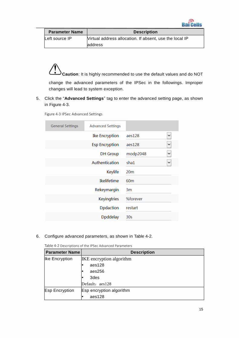
5. Click the “Advanced Settings” tag to enter the advanced setting page, as shown
in Figure 4-3.
Figure 4-3 IPSec Advanced Settings
6. Configure advanced parameters, as shown in Table 4-2.
Table 4-2 Descriptions of the IPSec Advanced Parameters
Parameter Name Description
Ike Encryption IKE encryption algorithm
aes128
aes256
3des
Default:aes128
Esp Encryption Esp encryption algorithm
aes128

16
Parameter Name Description
aes256
3des
Default:aes128
DH Group DH group
modp768
modp1024
modp1536
modp2048
modp4096
Default:modp1024
Authentication Authentication algorithm
sha1
sha512
Default:sha1
Keylife Ipsec sa renegotiation time
Time format (s seconds, m minutes, h hours)
Default:20m
Ikelifetime Ike sa renegotiation time
Time format (s seconds, m minutes, h hours)
Default:60m
Rekeymargin Renegotiation time before the expiry of Ikelifetime (negotiate
the Ike sa’s expire time before the expiry of Ikelifetime).
Time format (s seconds, m minutes, h hours)
Default:3m
Keyingtries Renegotiation attempts after the Ike negotiation fails
Default: 3
Dpdaction Action to take on spot of a gateway exception
none
clear
hold
restart
Default: restart
Dpddelay Time interval for sending the dpd detection message
Time format (s seconds, m minutes, h hours)
Default:30s
7. If there is more IPSec gateways to add, click “ADD” and configure the parameters as
stated above.
8. Click “SAVE” to complete the IPSec configuration.

17
5. Synchronization Configuration
BaiCells supports multiple synchronization means. The default priority among these
synchronizations is as follows: GPS synchronization, 1588V2 synchronization, and the air
interface synchronization. Users can choose the proper synchronization according to their
actual needs in network planning.
Note:
Air interface synchronization is not yet supported by the current version. Use GPS or 1588V2 for
synchronization instead.
GPS Synchronization
Using GPS synchronization, the availability of GPS antennas is required.
1. In the navigation column in the left, select “BTS Settings > Sync Settings”.
2. Click in the “GPS Sync” area, select “Enable” as shown in Figure 5-1.
Figure 5-1 Configure GPS Synchronization
3. Click “SAVE” to settle the GPS synchronization.
1588V2 Synchronization
1. Click in the “1588 Sync” area, select “Enable” as shown in Figure 5-2.
Figure 5-2 Configure 1588V2 Synchronization
2. Click “SAVE” to settle the 1588V2 synchronization.
Air Interface Synchronization
Air interface synchronization is not yet supported in the current version.


19
6. Software Upgrade
When the preset version does not meet the actual need, the base station shall initiate
a software upgrade. Local upgrade is supported.
Firmware Upgrade
6.1.1 Upgrade
1. In the navigation column in the left, select “System Settings > Firmware
Upgrade” as shown in Figure 6-1.
Figure 6-1 Firmware Upgrade
2. The user downloads the firmware of interest, and save it in the web client
computer.
3. Click “Browse” to select the firmware file saved.
4. Double check and then click “Flash IMAGE…”
5. In the pop-up window click “PROCEED”.
Wait 5min for the base station to reboot.
In the “BTS Info > Basic Info” page, the upgraded version will be displayed in
“Software Version".

20
6.1.2 Rollback
Only one rollback operation is allowed for each upgrade. Under the rollback permission of
the base station, the software can roll back to the version before upgrade.
After the rollback, a new rollback will not be permitted until an upgrade has taken place.
To see whether there is any firmware version for rollback, the user can check the
presence of any version number in the “Previous Version” area of the “Version Rollback”
section. Any version number existing means a possible fallback, and a “-” means
impossible.
Click “CLICK FALLBCAK” and wait 5min for the reboot to complete.
In the “BTS Info > Basic Info” page, the version after rollback will be displayed in
“Software Version”.
Uboot Upgrade
1. In the navigation column in the left, select “System Settings > Uboot Upgrade”
as shown in Figure 6-2.
Figure 6-2 Uboot Upgrade
2. The user downloads the firmware of interest, and save it in the web client
computer.
3. Click “Browse” to select the firmware file saved.
4. Double check and then click “Flash IMAGE…”
Wait 5min for the base station to reboot.
Reload the page and the upgraded Uboot version will be displayed in “Current
Version".

21
7. Others Configuration
Configure eNodeB
1. Click “LTE Settings > eNodeB Settings” to enter the eNodeB setting page.
2. Input the “eNodeB name”.
An eNodeB name consists of English letters, numbers and special characters, with a
maximum length of 48 characters. By default it is empty.
3. Click “SAVE” to complete the eNodeB setting.
Configure Time
In order to get synchronized in time, the NTP service needs to be configured.
1. In the navigation column in the left, select “System Settings > Time Settings” to
enter the NTP setting page.
The page contains time zone service and NTP setting.
2. Configure the time zone service as shown in Figure 7-1.
Figure 7-1 Configure Time Zone
Click “SYNC WITH BROWSER” to synchronize the base station’s time and the
browser’s.
Click behind the time zone parameter to select the base station ’s residing time
zone.
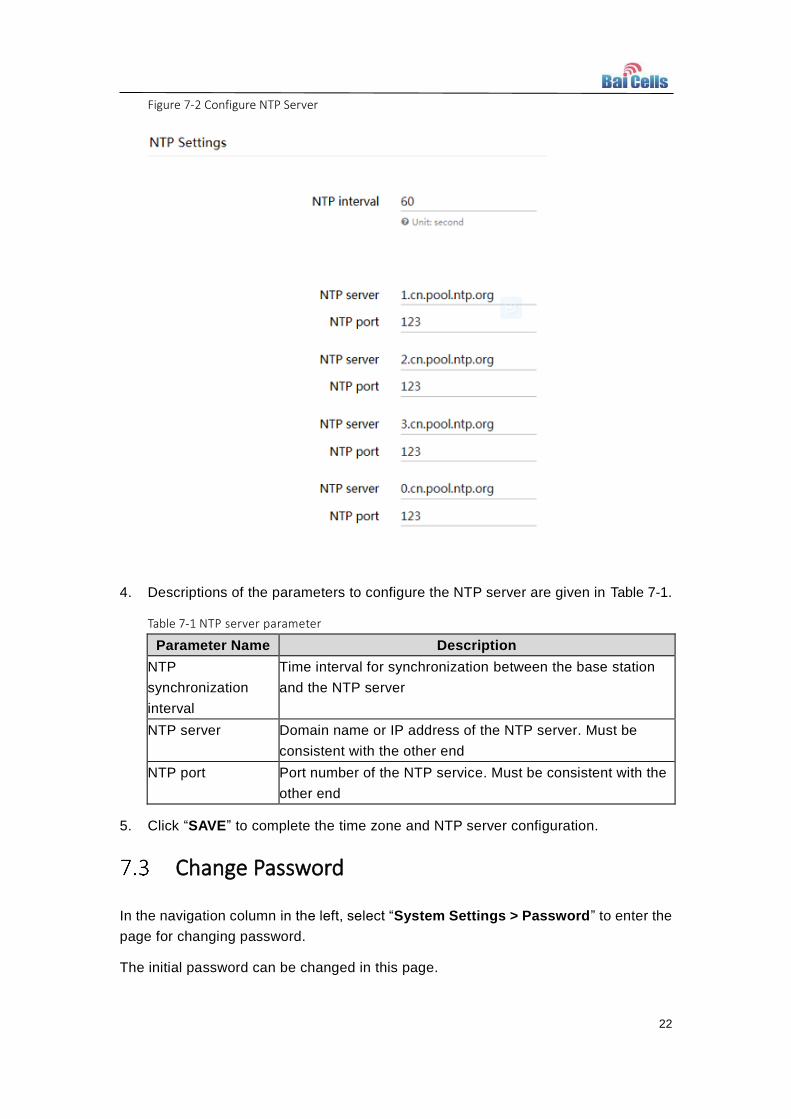
3. Configure the NTP server as shown in Figure 7-2.
The NTP is often used by base station as an external clock source and configured
according to the actual needs. Up to three NTP servers are supported by the base
station, where one for NTP service and the other two for backup.
22
Figure 7-2 Configure NTP Server
4. Descriptions of the parameters to configure the NTP server are given in Table 7-1.
Table 7-1 NTP server parameter
Parameter Name Description
NTP
synchronization
interval
Time interval for synchronization between the base station
and the NTP server
NTP server Domain name or IP address of the NTP server. Must be
consistent with the other end
NTP port Port number of the NTP service. Must be consistent with the
other end
5. Click “SAVE” to complete the time zone and NTP server configuration.
Change Password
In the navigation column in the left, select “System Settings > Password” to enter the
page for changing password.
The initial password can be changed in this page.

23
Export
This system supports the export of log files and configuration files.
1. In the navigation column in the left, select “System Settings > Export” to enter
the page for exporting data, as shown in Figure 7-3.
Figure 7-3 Export
2. Click “GENERATE LOG” to pop up a dialog box for download.
3. Click “SAVE” to select the directory for saving the log file and complete the
operation.
4. Click “GENERATE FILE” to pop up a dialog box for download.
5. Click “SAVE” to select the directory for saving the configuration file and complete
the operation.
Import
1. In the navigation column in the left, select “System Settings > Import” to enter
the page for exporting data.
2. Click “Browse” and in the pop-up dialog box “Choose File to Upload” select the
configuration file to import.
3. Click “UPLOAD FILE” to upload the configuration file to the base station.
Configure Restore
Once the restore setting operation is executed, the base station will reboot. Please be
cautious in doing this. Only the “BTS Settings” and the “LTE Settings” will be

24
restored.
Caution: The following security parameters should not be changed. Please
keep the default value.
Configure Security
1. In the navigation column in the left select “BTS Settings > Security Settings” as
shown in Figure 7-4.
Figure 7-4 Security Settings
2. Input the security parameters, whose descriptions are given in Table 7-2.
Table 7-2 Descriptions of the security parameters
Parameter Name Description
Ciphering Algorithm Encryption algorithm
Options:
EEA0(recommended)
128-EEA1
128-EEA2
128-EEA3
Default:EEA0
Integrity Algorithm Integrity protection algorithm
Options:
EIA0
128-EIA1
128-EIA2
128-EIA3
Default: 128-EIA1
3. Click “SAVE” to complete the security algorithm setting.

25
8. Advanced Configuration
Caution: Common operators are NOT recommended to modify the advanced
configuration below. It is better to keep the default values. For senior experts in
need, please treat it with great caution.
Mobility Settings
8.1.1 X2 Enable Switch
If the X2 connection is needed by the base station, enable it; otherwise, keep it
disabled. It is disabled by default.
1. Select “LTE Settings >X2 Enable Switch” to enter the page for
enabling/disabling the X2 establishment.
2. The system default value for “X2 Enable Switch” is “Disable”. If needed, change it
accordingly to “Enable.”
3. Click “SAVE” to complete the enabling/disabling of the X2 establishment.
8.1.2 GAP Settings
1. Select “LTE Settings > GAP Settings” to enter the GAP setting page.
Input the “Inter-Frequency Meas GAP” value. Either 1 or 2, and default is 1.
Descriptions:
1: GPA period of 40ms
2: GPA period of 80ms
2. Click “SAVE” to complete the GAP setting.
8.1.3 CSFB Parameter Settings
1. Select “LTE Settings > CSFB Parameter Settings” to enter the CSFB parameter
setting page, as shown in Figure 8-1.

26
Figure 8-1 CSFB Parameter Settings
2. Input the CSFB parameters, whose descriptions are given in Table 8-1.
Table 8-1 CSFB parameter descriptions
Parameter Name Description
CSFB PLMN RAT
Prior
System to fallback
LTE: non-fallback, no CSFB service
GSM: fall back to GSM for CSFB service
Default: LTE
GERAN CCO Whether to fall back to GSM by means of CCO
Default: no
3. Click “SAVE” to complete the CSFB parameter setting.
8.1.4 LTE Neighbour Frequency Settings
1. Select “LTE Settings > LTE Neighbour Freq Settings” to enter the page for setting
the LTE neighbor frequency, as shown in Figure 8-2.
Figure 8-2 LTE Neighbour Frequency Settings
Users can add, modify, and delete the LTE neighbor frequency. Up to eight LTE
neighbor frequencies can be set.
2. Click “ADD NEIGHBOUR FREQ” to enter the page for adding the LTE neighbor
frequency. Descriptions of related parameters are given in Table 8-2.

27
Table 8-2 Parameter descriptions for LTE neighbor frequency setting
Parameter Name Description
EARFCN Frequency point of the neighbor frequency
Q-RxLevMin Minimum access level. Only the received signal power
measured by the UE is higher than this threshold, the UE can
camp on this cell.
Q-OffsetRange Offset between the target candidate cell and the cell currently
camping on
Reselection Timer Expire time of the cell reselection timer
Reselection Prior Priority of the reselection to cells at this frequency
Reselection
ThreshX High
Reselection threshold for higher priority inter-band frequency
This parameter represents the access threshold level, at
which the UE will leave the serving cell and reselect another
cell at the target frequency, given that the target frequency
cell has a cell reselection priority higher than the serving one.
Reselection
ThreshX Low
Reselection threshold for lower priority inter-band frequency.
This parameter represents the access threshold level, at
which the UE will leave the serving cell and reselect another
cell at the target frequency, given that the target frequency
cell has an absolute priority lower than the serving one.
P-Max Maximum transmit power a UE allowed to use in the uplink,
for limiting the transmit power of the UE within this cell
3. Click “SAVE” to complete the LTE neighbor frequency setting.
8.1.5 LTE Neighbour Cell Settings
1. Click “LTE Settings > LTE Neighbour Cell Settings” to enter the page for setting
the LTE neighbor cells, as shown in Figure 8-3.
Figure 8-3 LTE Neighbour Cell Settings

28
Users can add, modify, and delete LTE neighbor cells. Up to 16 LTE neighbor cells
can be set.
2. Click “ADD NEIGHBOUR CELL” to enter the page for adding LTE neighbor cells.
The descriptions of related parameters are given in Table 8-3.
Table 8-3 Parameter description for LTE neighbor cell setting
Parameter Name Description
PLMN PLMN that the neighbor cell belongs to
CELL ID Cell ID of the neighbor cell
EARFCN Frequency point of the neighbor cell
PCI PCI of the neighbor cell
Qoffset Frequency offset the neighbor cell
CIO Cell offset of the neighbor cell
TAC Tracking area code of the neighbor cell
3. Click “SAVE” to complete the setting of the LTE neighbor cells.
8.1.6 TD-S Neighbour Frequency Settings
1. Select “LTE Settings > TD-S Neighbour Freq Settings” to enter the page for
setting the TD-S neighbor frequency, as shown in Figure 8-4.
Figure 8-4 TD-S Neighbour Frequency Settings
Users can add, modify, and delete the TD-S neighbor frequency. Up to 16 LTE
neighbor frequency can be set.
2. Click “ADD NEIGHBOUR FREQ” to enter the page for adding TD-S neighbor
frequency. Descriptions of related parameters are given in Table 8-4.
Table 8-4 Parameter descriptions on setting neighbor frequency
Parameter Name Description
TDD Mode Three modes of the TDD chip rate
ARFCN Frequency point of the TDD neighbor frequency
29
Parameter Name Description
Q-RxLevMin Minimum access level. Only the received signal power
measured by the UE is higher than this threshold, the UE can
camp on this cell.
Reselection Prior Priority of the reselection to cells at this frequency
Reselection ThreshX
High
Reselection threshold for higher priority inter-band frequency.
This parameter represents the access threshold level, at
which the UE will leave the serving cell and reselect another
cell at the target frequency, given that the target frequency
cell has a cell reselection priority higher than the serving one
Reselection ThreshX
Low
Reselection threshold for lower priority inter-band frequency.
This parameter represents the access threshold level, at
which the UE will leave the serving cell and reselect another
cell at the target frequency, given that the target frequency
cell has an absolute priority lower than the serving one.
P-Max Maximum transmit power a UE allowed to use in the uplink,
for limiting the transmit power of the UE within this cell
Q-Offset Offset between the target candidate cell and the cell currently
camping on
3. Click “SAVE” to complete the setting of the TD-S neighbor frequency.
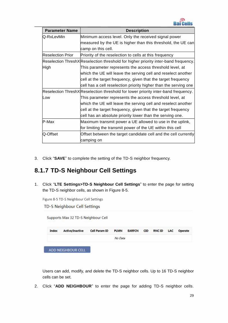
8.1.7 TD-S Neighbour Cell Settings
1. Click “LTE Settings>TD-S Neighbour Cell Settings” to enter the page for setting
the TD-S neighbor cells, as shown in Figure 8-5.
Figure 8-5 TD-S Neighbour Cell Settings
Users can add, modify, and delete the TD-S neighbor cells. Up to 16 TD-S neighbor
cells can be set.
2. Click “ADD NEIGHBOUR” to enter the page for adding TD-S neighbor cells.

30
Descriptions of related parameters are given in Table 8-5.
Table 8-5 Parameter descriptions for setting TD-S neighbor cells
Parameter Name Description
CPI Used to separate cells in traffic slots
PLMN PLMN that the neighbor cell belongs to
ARFCN Frequency point of the neighbor cell
CELL ID Cell ID of the neighbor cell
RNC ID ID of the neighbor cell’s RNC
LAC Location area code of the neighbor cell
3. Click “SAVE” to complete the setting of the TD-S neighbor cells.
8.1.8 GSM Neighbour Frequency Settings
1. Select “LTE Settings> GSM Neighbour Freq Settings” to enter the page for setting
GSM neighbor frequency, as shown in Figure 8-6.
Figure 8-6 GSM Neighbour Frequency Settings
Users can add, modify, and delete the GSM neighbor frequency. Up to 8 GSM
neighbor frequencies can be set.
2. Click “ADD NEIGHBOUR FREQ” to enter the page for adding GSM neighbor
frequency. Descriptions of related parameters are given in Table 8-6.
Table 8-6 Parameter descriptions for setting the GSM neighbor frequency
Parameter Name Description
Band GSM neighbor band
BCCH ARFCN Frequency point of the GSM neighbor frequency
Q-RxLevMin Minimum access level
Only when the received signal power measured by the UE is
higher than this threshold, the UE is allowed to camp on this

31
Parameter Name Description
cell.
Reselection Prior Priority of the reselection to cells at this frequency
Reselection ThreshX
High
Reselection threshold for higher priority inter-band frequency.
This parameter represents the access threshold level, at
which the UE will leave the serving cell and reselect another
cell at the target frequency, given that the target frequency
cell has a cell reselection priority higher than the serving one
Reselection ThreshX
Low
Reselection threshold for lower priority inter-band frequency.
This parameter represents the access threshold level, at
which the UE will leave the serving cell and reselect another
cell at the target frequency, given that the target frequency
cell has an absolute priority lower than the serving one.
3. Click “SAVE” to complete the setting of the GSM neighbor frequency.
8.1.9 GSM Neighbour Cell Settings
1. Select “LTE Settings>GSM Neighbour Cell Settings” to enter the page of setting
GSM neighbor cell, as shown in Figure 8-7.
Figure 8-7 GSM Neighbour Cell Settings
Users can add, modify, and delete GSM neighbor cells. Up to 16 GSM neighbor cells
can be set.
2. Click “ADD NEIGHBOUR CELL” to enter the page for adding GSM neighbor cells,
as shown in Table 8-7.
Table 8-7 Parameter descriptions for setting GSM neighbor cells
Parameter Name Description
PLMN ID PLMN that the neighbor cell belongs to
LAC Location area code of the neighbor cell
BSIC Base station identification code of the neighbor cell
CELL ID Cell ID of the neighbor cell

32
Parameter Name Description
Band Ind BAND of the neighbor cell
BCCH ARFCN Frequency point of the neighbor cell
3. Click “SAVE” to complete the setting of the GSM neighbor cell.
Measurement Configuration
8.2.1 A1 Event Threshold
A1 event: the serving cell better than the absolute threshold. The A1 event can be
used to turn off certain inter-cell measurements.
1. Select “LTE Settings > A1 Event Threshold” to enter the page for setting the A1
event threshold.
2. Input the parameter of the A1 event threshold, whose description is given in Table
8-8.
Table 8-8 Parameter descriptions for A1 event
Parameter Name Description
A1 Event RSRP
Threshold
the RSRP threshold parameter of the A1 event
Options: 0~97
Default: 90
3. Click “SAVE” to complete the setting of the A1 event threshold.
8.2.2 A2 Event Threshold
1. Select “LTE Settings > A2 Event Threshold” to enter the page for setting the A2
event threshold, as shown in Figure 8-8.

33
Figure 8-8 A2 Event Threshold
2. Input the parameter of the A1 event threshold, whose description is given in Table
8-9.
Table 8-9 Parameter descriptions for A2 event
Parameter Name Description
Multiple A2 Event Whether to enable multiple A2 events
Default: disabled
LTE A2 RSRP Threshold the RSRP threshold parameter of the A2 event
Blind Redirect A2 RSRP
Threshold
the RSRP threshold parameter of the blind redirect A2
event
IRAT Data A2 RSRP
Threshold
the RSRP threshold parameter of the data service A2
event
IRAT Volte A2 RSRP
Threshold
the RSRP threshold parameter of the voice service A2
event
3. Click “SAVE” to complete the setting of the A2 event threshold.
8.2.3 A3 Event Threshold
1. Select “LTE Settings > A3 Event Threshold” to enter the page for setting the A3
event threshold.
2. Input the “A3 Event Offset” threshold value.
Range: -30~30, default: 10.
3. Click “SAVE” to complete the setting of the A3 event threshold.

34
8.2.4 A5 Event Threshold
1. Select “LTE Settings > A5 Event Threshold” to enter the page for setting the A5
event threshold, as shown in Figure 8-9.
Figure 8-9 A5 Event Threshold
2. Input the A5 event threshold parameter. Descriptions of the parameters are given
in Table 8-10.
Table 8-10 Parameter descriptions for A5 event threshold
Parameter Name Description
ANR A5 RSRP Threshold1 RSRP threshold parameter 1 of the A5 event
Default: 70
ANR A5 RSRP Threshold2 RSRP threshold parameter 2 of the A5 event
Default: 65
A5 Event RSRP Threshold1 RSRP threshold parameter 1 of the ANR A5 event
Default: 75
A5 Event RSRP Threshold 2 RSRP threshold parameter 2 of the ANR A5 event
Default: 50
3. Click “SAVE” to complete the setting of the A5 event threshold.
8.2.5 B2 Event Threshold
1. Select “LTE Settings > B2 Event Threshold” to enter the page for setting the B2
event threshold, as shown in Figure 8-10.

35
Figure 8-10 B2 Event Threshold
2. Input the B2 event threshold parameter. Descriptions of the parameters are given
in Table 8-11.
Table 8-11 Parameter descriptions for B2 event threshold
Parameter Name Description
UTRA B2 RSRP
Threshold1
Threshold parameter 1 of the UTRA TDS B2 event
Default: 70
UTRA B2 RSRP
Threshold 2
Threshold parameter 2 of the UTRA TDS B2 event
Default: 0
GERAN B2 RSRP
Threshold1
Threshold parameter 1 of the GERAN B2 event
Default: 10
GERAN B2 RSRP
Threshold2
Threshold parameter 2 of the GERAN B2 event
Default: 20
3. Click “SAVE” to complete the setting of the B2 event threshold.
Scheduling Algorithm
Scheduling is an important insurance for the good operation of the wireless data
service. Scheduling algorithms have a general impact on key performance indicators
like the cell throughput, cell edge user throughput, VoIP capacity, and QoS of data
service.
Scheduling strategies commonly used are:
MAXC/I algorithm: allocate the resource and opportunities to terminals in favor of
those with good channel quality. QoS not taken into account, and memory not used.
PFS algorithm: balance between user channel quality and fairness, both cell

36
throughput and user fairness taken into account.
RR algorithm: allocate the resource and opportunities to all terminals equally. QoS
not taken into account, and memory not used.
1. Select “LTE Settings > Scheduling Algorithm” to enter the page for setting the
scheduling algorithm, as shown in Figure 8-11.
Figure 8-11 Scheduling Algorithm
2. Input the scheduling algorithm parameter. Descriptions of the parameters are
given in Table 8-12.
Table 8-12 Parameter descriptions for the scheduling algorithms
Parameter Name Description
UL Schedule Type MAC uplink scheduling algorithm
0:MAXC/I algorithm
1:PFS algorithm
2:RR algorithm
Default: 2
DL Schedule Type MAC downlink scheduling algorithm
0:MAXC/I algorithm
1:PFS algorithm
2:RR algorithm
Default: 2
3. Click “SAVE” to complete the setting of the scheduling algorithm.
PCI Range Settings
1. Select “LTE Settings > PCI Range Settings” to enter the page for setting the PCI
range, as shown in Figure 8-12.

37
Figure 8-12 PCI Range Settings
2. Input the setting parameter of the PCI range, whose descriptions are given in
Table 8-13.
Table 8-13 Parameter descriptions for setting the PCI range
Parameter Name Description
Start PCI Start number of the cell allocated PCI
Default: 1
PCI Range Range of the cell PCI (relative to the start number)
Default: 400
3. Click “SAVE” to complete the setting of the PCI range.
Random Access Parameters
1. Select “LTE Settings > Random Access Parameters” to enter the page for setting
the access parameters, as shown in Figure 8-13.
Figure 8-13 Random Access Parameters
2. Input the parameters of the access setting, whose descriptions are given in Table
8-14.

38
Table 8-14 Descriptions for setting the access parameters
Parameter Name Description
Prach-Configuration Index PRACH configuration index, broadcasted to the UE
via SIB2
Range: 0~63
Zero Correlation Zone
Config
prachCyclicShiftConfig, used to generate the
preamble sequence.
Range: 0~63
3. Click “SAVE” to complete the setting of the access parameters.
Capacity Parameters
1. Select “LTE Settings > Capacity Parameters” to enter the page for setting the
capacity parameters, as shown in Figure 8-14.
Figure 8-14 Capacity Parameters
2. Input the parameters of the capacity setting, whose descriptions are given in Table
8-15.
Table 8-15 Parameter descriptions for the capacity setting
Parameter Name Description
Max UE Number 96 Number of active users the cell can handle at the same
time
Max Mac RNTI Number Maximum number of RNTI in MAC layer
3. Click “SAVE” to complete the setting of the capacity parameters.
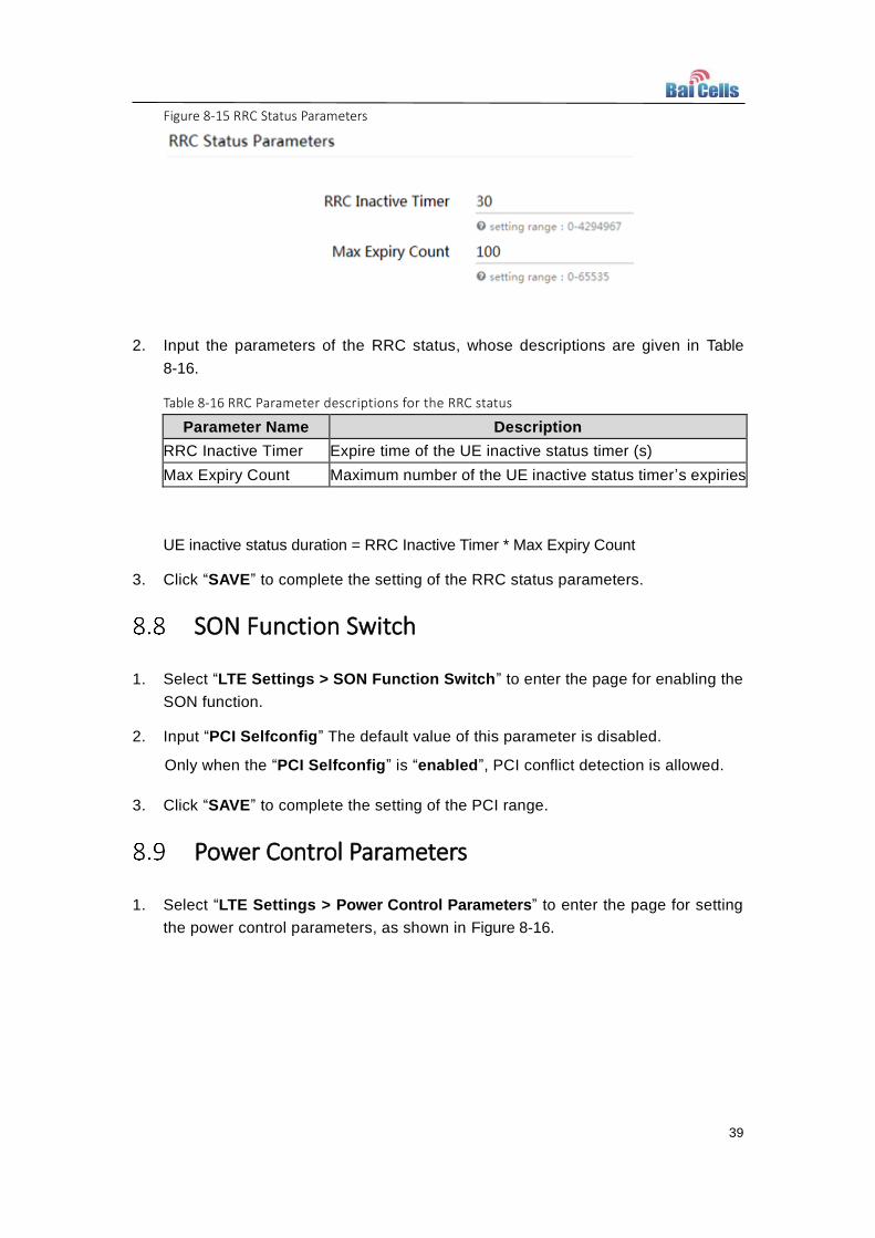
RRC Status Parameters
1. Select “LTE Settings > RRC Status Parameters” to enter the page for setting the
RRC status parameters, as shown in Figure 8-15.
39
Figure 8-15 RRC Status Parameters
2. Input the parameters of the RRC status, whose descriptions are given in Table
8-16.
Table 8-16 RRC Parameter descriptions for the RRC status
Parameter Name Description
RRC Inactive Timer Expire time of the UE inactive status timer (s)
Max Expiry Count Maximum number of the UE inactive status timer’s expiries
UE inactive status duration = RRC Inactive Timer * Max Expiry Count
3. Click “SAVE” to complete the setting of the RRC status parameters.
SON Function Switch
1. Select “LTE Settings > SON Function Switch” to enter the page for enabling the
SON function.
2. Input “PCI Selfconfig” The default value of this parameter is disabled.
Only when the “PCI Selfconfig” is “enabled”, PCI conflict detection is allowed.
3. Click “SAVE” to complete the setting of the PCI range.
Power Control Parameters
1. Select “LTE Settings > Power Control Parameters” to enter the page for setting
the power control parameters, as shown in Figure 8-16.

40
Figure 8-16 Power Control Parameters
2. Input the parameters of power control, whose descriptions are given in Table 8-17.
Table 8-17 Parameter descriptions for the power control
Parameter Name Description
p-MAX Limit on the UE’s maximum transmit power
Reference Signal Power Transmit power of the reference signals
Power Ramping Step size of the PRACH’s power ramping
Preamble Init Target
Power
Initial power of PRACH
Pusch Power Control Enable/disable the PUSCH format3’s power control
Pucch Power Control Enable/disable the PUCCH format3’s power control
P0 PUSCH Initial transmit power of PUSCH
P0 PUCCH Initial transmit power of PUCCH
3. Click “SAVE” to complete the setting of the power control parameters.
Tx And Rx Parameters
1. Select “LTE Settings > Tx AND Rx Parameters” to enter the page for setting the
transmit and receive parameters.

41
2. Input the “PHY RXGAIN” parameter, which is used to set the radio frequency
receiving gain in the uplink.
3. Click “SAVE” to complete the setting of the transmission and receive parameters.
Measurement Control Parameter
1. Select “LTE Settings > Measurement Control Parameter” to enter the page for
setting the measurement control parameters, as shown in Figure 8-17.
Figure 8-17 Measurement Control Parameter
2. Input the parameters of measurement control, whose descriptions are given in
Table 8-18.
Table 8-18 Parameter descriptions for measurement control
Parameter Name Description
HYSTERESIS This parameter refers to the hysteresis of the handover
measurement event, and is used to avoid the frequent
triggering of cell handover evaluation due to the fluctuation in
wireless signals.
TIME TO TRIGGER Delay time of the handover measurement event
3. Click “SAVE” to complete the setting of the measurement control parameters.
Cell Selection Parameter
1. Select “LTE Settings > Cell Selection Parameter” to enter the page for setting the
cell selection parameters, as shown in Figure 8-18.

42
Figure 8-18 Cell Selection Parameter
2. Input the parameters of measurement control, whose descriptions are given in
Table 8-19.
Table 8-19 Parameter descriptions for PCI range setting
Parameter Name Description
QRX LEVEL MIN SIB1 Minimum level acceptable by cell selection
QRX LEVEL MIN
OFFSET
Minimum level offset needed by cell selection
3. Click “SAVE” to complete the setting of cell selection parameters.
Cell Reselection Parameter
1. Select “LTE Settings > Cell Reselection Parameter” to enter the page for setting
the cell reselection parameters, as shown in Figure 8-19.

43
Figure 8-19 Cell Reselection Parameter
2. Input the parameters of cell reselection, whose descriptions are given in Table
8-20.
Table 8-20 Parameter descriptions for cell reselection
Parameter Name Description
S INTRA SEARCH Intra-band measurement threshold
S_NON INTRA
SEARCH
Inter-band measurement threshold
QRX LEVEL MIN SIB3 Minimum level for reselection
QHYST Delay time for reselection
Reselection Priority Priority for reselection
SERVING LOW Threshold for selection to cells of low priority
ALLOWED MEAS BW
sib3
Measurement bandwidth allowed
3. Click “SAVE” to complete the setting of the cell reselection parameters.

44
Terminology & Acronym
Acronym Full Name
PCI Physical Cell Identifier
MME Mobility Management Entity
PLMN Public Land Mobile Network
TAC Tracking Area Code
DHCP Dynamic Host Configuration Protocol
PPPOE Point to Point Protocol over Ethernet
GPS Global Positioning System
NTP Network Time Protocol
PAP Password Authentication Protocol
CHAP Challenge Handshake Authentication Protocol
CSFB Circuit Switched Fallback
RSRP Reference Signal Receiving Power