Baha® Systems
32
FOR PROFESSIONALS For Cochlear ™ Baha ® DermaLock ™ Surgical Procedure COCHLEAR ™ Baha ® Systems SURGERY GUIDE
-
Upload
nguyenkiet -
Category
Documents
-
view
227 -
download
0
Transcript of Baha® Systems

FOR PROFESSIONALS
For Cochlear™ Baha®
DermaLock™ Surgical Procedure
COCHLEAR™
Baha® SystemsSURGERY GUIDE
AcknowledgementsThe protocol detailed in this manual originates from the clinical work carried out by:
Pete Weber, M.D., MBA, Chief Medical Officer, Cochlear Americas
This surgical guide sets forth detailed recommended procedures for using Cochlear™ Baha® surgical components and instruments. It offers guidance needed for performing the procedure but, as with any technical guide, the surgeon must consider the particular needs of each patient and make appropriate adjustments when required. The techniques shown in this guide are provided for your consideration only, and do not constitute direct medical advice from Cochlear. This guide is not a substitute for actual medical education and hands-on training.
Cochlear accepts no responsibility for any adverse outcomes if used with products not recommended by Cochlear. Close cooperation in an interdisciplinary team is essential for a successful outcome. Hands-on surgical workshops are available from Cochlear. Contact your local Cochlear office for details.
2 |
Contents
Introduction 5
Preparations 6
Baha FAST surgery 11
Baha two-stage surgery 17
Aftercare 24
Complications 26
References 29
Notes 30
NOTE:
Images in this guide are not to scale.
Not all products are available in all markets. Product availability is subject to regulatory approval in the respective markets.
Baha FAST surgery is the same as one-stage surgery.
This guide is applicable for the DermaLock Implant with Abutment (BIA400), and the BI300 Implants used with the DermaLock Abutments (BA400). These products are used for Baha surgery with soft tissue preservation.
Traditional Baha surgery with soft tissue removal is carried out using BA210 Abutments, BA300 Abutments or previous generation Baha abutments. For more information, see the Baha Surgery guide for the BI300 Implant system (BUN004).
| 3

4 |
| 5
Introduction
Since 1977, the Cochlear Baha Bone Conduction Implant has proven successful for thousands of patients worldwide. The system – which combines a small titanium implant, an abutment, and a sound processor – has yielded excellent results for certain patient groups, particularly for thoseindividuals with single-sided sensorineural deafness,conductive, and mixed hearing loss.1
The long-term predictability and success of Baha implants results from the creation of an active bond between the titanium implant and the surrounding bone tissue – a process known as osseointegration. The use of a precise implantation technique is vital to successful, long-term osseointegration.
Since the introduction of the Baha System, the surgical procedure for implantation has been modified by surgical teams worldwide to further improve the results and to shorten the surgery time.
The Cochlear Baha DermaLock Abutments have been specifically designed to facilitate a minimally invasive surgical technique that preserves soft tissue.
When selecting a surgical approach, the techniques in this guide provide the recommended alternatives.
Technique selection
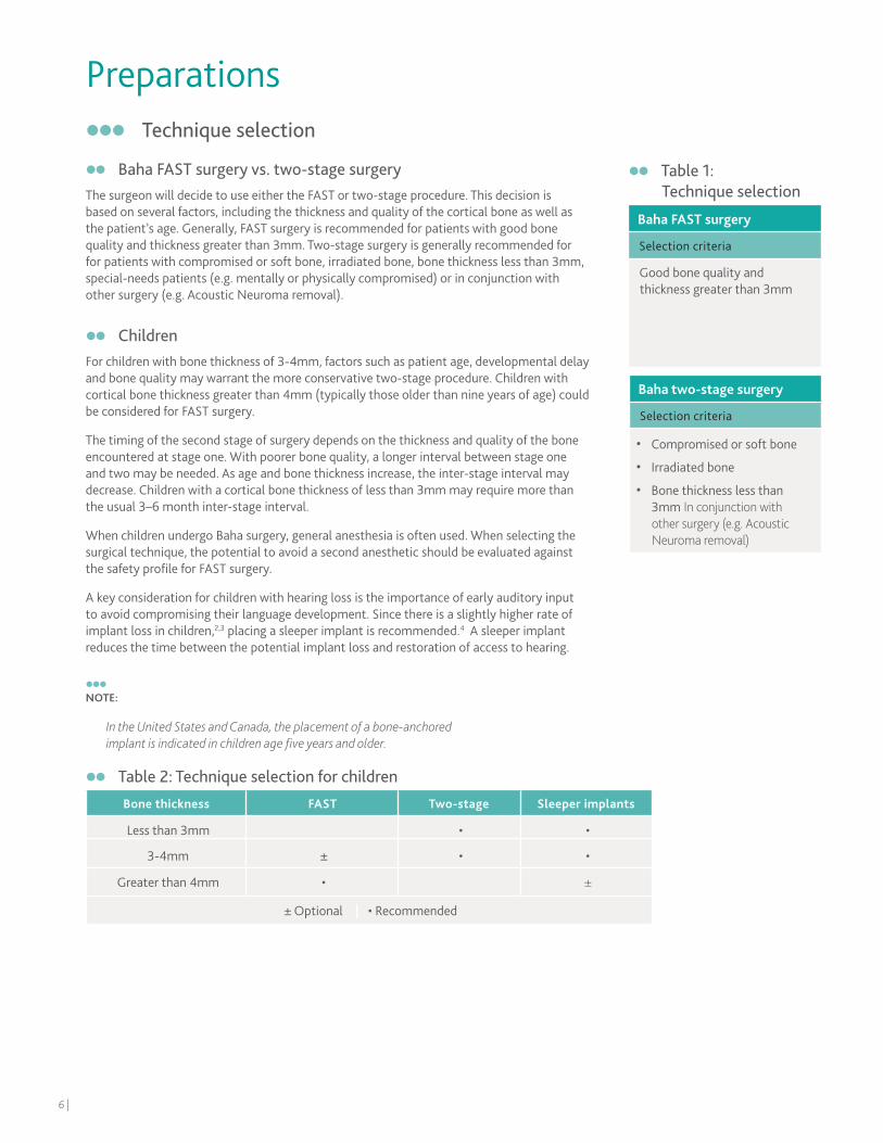
Baha FAST surgery vs. two-stage surgeryThe surgeon will decide to use either the FAST or two-stage procedure. This decision is based on several factors, including the thickness and quality of the cortical bone as well as the patient’s age. Generally, FAST surgery is recommended for patients with good bone quality and thickness greater than 3mm. Two-stage surgery is generally recommended for for patients with compromised or soft bone, irradiated bone, bone thickness less than 3mm, special-needs patients (e.g. mentally or physically compromised) or in conjunction with other surgery (e.g. Acoustic Neuroma removal).
ChildrenFor children with bone thickness of 3-4mm, factors such as patient age, developmental delay and bone quality may warrant the more conservative two-stage procedure. Children with cortical bone thickness greater than 4mm (typically those older than nine years of age) could be considered for FAST surgery.
The timing of the second stage of surgery depends on the thickness and quality of the bone encountered at stage one. With poorer bone quality, a longer interval between stage one and two may be needed. As age and bone thickness increase, the inter-stage interval may decrease. Children with a cortical bone thickness of less than 3mm may require more than the usual 3–6 month inter-stage interval.
When children undergo Baha surgery, general anesthesia is often used. When selecting the surgical technique, the potential to avoid a second anesthetic should be evaluated against the safety profile for FAST surgery.
A key consideration for children with hearing loss is the importance of early auditory input to avoid compromising their language development. Since there is a slightly higher rate ofimplant loss in children,2,3 placing a sleeper implant is recommended.4 A sleeper implant reduces the time between the potential implant loss and restoration of access to hearing.
NOTE:
In the United States and Canada, the placement of a bone-anchored implant is indicated in children age five years and older.
Baha FAST surgery
Selection criteria
Good bone quality and thickness greater than 3mm
Baha two-stage surgery
Selection criteria
• Compromised or soft bone
• Irradiated bone
• Bone thickness less than 3mm In conjunction with other surgery (e.g. Acoustic Neuroma removal)
Preparations
Table 1: Technique selection
Bone thickness FAST Two-stage Sleeper implants
Less than 3mm • •
3-4mm ± • •
Greater than 4mm • ±
± Optional | • Recommended
Table 2: Technique selection for children
6 |
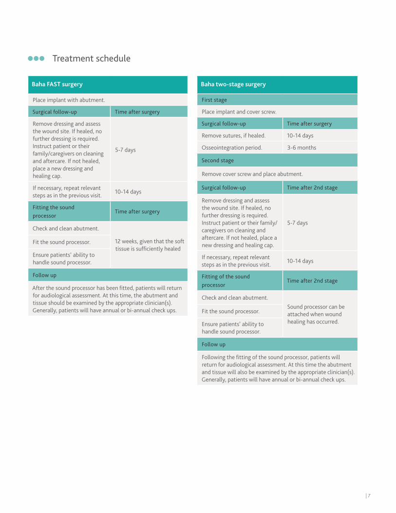
Treatment schedule
Baha FAST surgery
Place implant with abutment.
Surgical follow-up Time after surgery
Remove dressing and assess the wound site. If healed, no further dressing is required. Instruct patient or their family/caregivers on cleaning and aftercare. If not healed, place a new dressing and healing cap.
5-7 days
If necessary, repeat relevant steps as in the previous visit.
10-14 days
Fitting the sound processor
Time after surgery
Check and clean abutment.
12 weeks, given that the soft tissue is sufficiently healed
Fit the sound processor.
Ensure patients’ ability to handle sound processor.
Follow up
After the sound processor has been fitted, patients will return for audiological assessment. At this time, the abutment andtissue should be examined by the appropriate clinician(s). Generally, patients will have annual or bi-annual check ups.
Baha two-stage surgery
First stage
Place implant and cover screw.
Surgical follow-up Time after surgery
Remove sutures, if healed. 10-14 days
Osseointegration period. 3-6 months
Second stage
Remove cover screw and place abutment.
Surgical follow-up Time after 2nd stage
Remove dressing and assess the wound site. If healed, no further dressing is required.Instruct patient or their family/caregivers on cleaning and aftercare. If not healed, place a new dressing and healing cap.
5-7 days
If necessary, repeat relevant steps as in the previous visit.
10-14 days
Fitting of the sound processor
Time after 2nd stage
Check and clean abutment.Sound processor can be attached when wound healing has occurred.
Fit the sound processor.
Ensure patients’ ability to handle sound processor.
Follow up
Following the fitting of the sound processor, patients will return for audiological assessment. At this time the abutmentand tissue will also be examined by the appropriate clinician(s). Generally, patients will have annual or bi-annual check ups.
| 7
Preparations for surgeryPrepare the patient as for any surgical procedure, i.e. sterilize the incision area. Local or general anesthesia can be used for adult patients. When children undergo Baha surgery general anesthesia is most often used.
NOTE:
1
2
Selecting the implant siteEven though the surgeon will ultimately select the implant site, successful treatment relies on an interdisciplinary approach that includes consultation with other clinicians involved in the case, as well as the patient and/or the patient’s family/caregiver. Choosing the appropriate implant site requires attention to the following factors and considerations:
• Audiological factors — Baha surgery is indicated as a treatment for patients with with single-sided sensorineural deafness (SSD), as well as conductive or mixed hearing loss. For patients with single-sided sensorineural deafness (SSD), place the implant on the deaf side.
In patients with a bilateral hearing loss, bilateral fitting is recommended. Studies show that the patient benefits from bilateral fitting in terms of greater stimulation level, better directional hearing and space perception as well as overall better speech understanding in noise.5
In case of unilateral fitting, place the implant on the side with the best cochlear function (i.e. best bone conduction thresholds).
• Physiological factors — Incorrect implant placement too far from the cochlea can change the audiological outcome.6 Estimate the site location in cases of complete aural atresia, or place the Baha in the parietal cortex rather than the thicker mastoid bone in children with craniofacial abnormalities. Move the site posteriorly (generally 60-65mm from ear canal) for children who will undergo autogenous reconstruction.
• Manual dexterity — Ensure patients’ (or families’/caregivers’) ability to utilize controls as well as remove and replace the sound processor.
• Head gear — Special consideration is warranted for patients who regularly wear a hat or helmet for work or certain activities (e.g. construction workers and cyclists).
• For patients with mixed or conductive loss:
Driving habits — Patients that regularly drive with a passenger seated next to or behind them usually prefer their implant on the side facing the passenger.
Telephone use — Patients that frequently use the telephone prefer the implant on the side opposite to their writing hand.
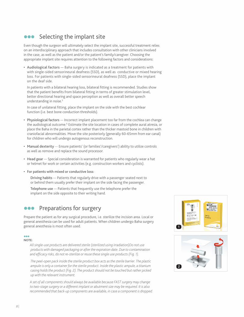
All single-use products are delivered sterile (sterilized using irradiation)Do not use products with damaged packaging or after the expiration date. Due to contamination and efficacy risks, do not re-sterilize or reuse these single use products (Fig. 1).
The peel-open pack inside the sterile product box acts as the sterile barrier. The plastic ampule is only a container for the sterile product. Inside the plastic ampule, a titanium casing holds the product (Fig. 2). The product should not be touched but rather picked up with the relevant instrument.
A set of all components should always be available because FAST surgery may change to two-stage surgery or a different implant or abutment size may be required. It is also recommended that back-up components are available, in case a component is dropped.
8 |
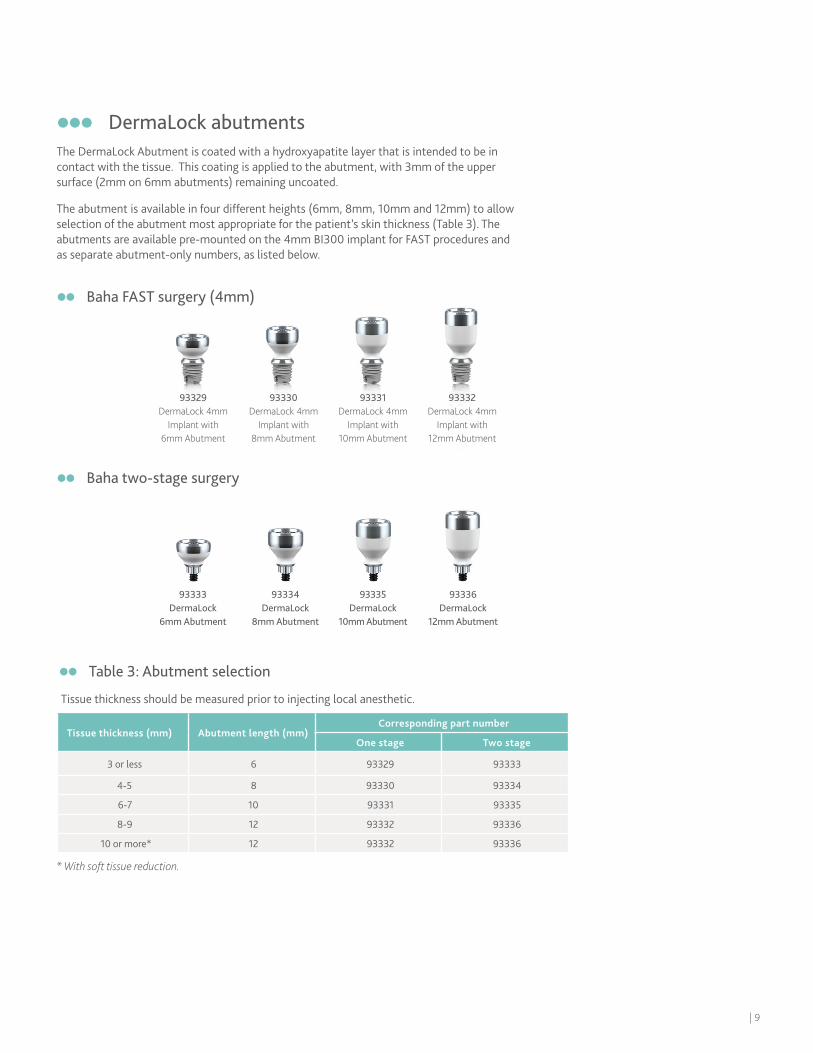
DermaLock abutmentsThe DermaLock Abutment is coated with a hydroxyapatite layer that is intended to be in contact with the tissue. This coating is applied to the abutment, with 3mm of the upper surface (2mm on 6mm abutments) remaining uncoated.
The abutment is available in four different heights (6mm, 8mm, 10mm and 12mm) to allow selection of the abutment most appropriate for the patient’s skin thickness (Table 3). The abutments are available pre-mounted on the 4mm BI300 implant for FAST procedures and as separate abutment-only numbers, as listed below.
93329 DermaLock 4mm
Implant with 6mm Abutment
93333 DermaLock
6mm Abutment
93330 DermaLock 4mm
Implant with 8mm Abutment
93334DermaLock
8mm Abutment
93331 DermaLock 4mm
Implant with 10mm Abutment
93335 DermaLock
10mm Abutment
93332 DermaLock 4mm
Implant with 12mm Abutment
93336 DermaLock
12mm Abutment
Baha two-stage surgery
Baha FAST surgery (4mm)
Table 3: Abutment selection
Tissue thickness should be measured prior to injecting local anesthetic.
Tissue thickness (mm) Abutment length (mm)Corresponding part number
One stage Two stage
3 or less 6 93329 93333
4-5 8 93330 93334
6-7 10 93331 93335
8-9 12 93332 93336
10 or more* 12 93332 93336
* With soft tissue reduction.
| 9

10 |
Baha FAST surgery
Generally, FAST surgery is recommended for patients with good bone quality and thickness. FAST surgery is performed in one stage and the procedure involves placing an implant with a pre-mounted abutment.
This section provides step-by-step instructions for Baha FAST surgery with soft tissue preservation, or minimal soft tissue removal where required. Because a FAST surgery may need to be converted to a two-stage surgery intra-operatively, it is recommended to keep a 3mm implant and a 3mm widening drill in the OR.
| 11
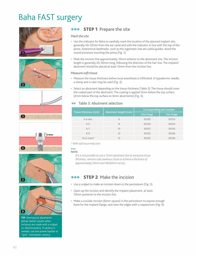
STEP 1 Prepare the site Mark the site• Use the indicator for Baha to carefully mark the location of the planned implant site,
generally 50–55mm from the ear canal and with the indicator in line with the top of the pinna. Anatomical landmarks, such as the zygomatic line are useful guides. Avoid the sound processor touching the pinna (Fig. 1).
• Mark the incision line approximately 10mm anterior to the abutment site. The incision length is generally 20-30mm long, following the direction of the hair line. The implant/abutment should be placed at least 10mm from the incision line.
Measure soft tissue• Measure the tissue thickness before local anesthesia is infiltrated. A hypodermic needle,
a clamp and a ruler may be used (Fig. 3).
• Select an abutment depending on the tissue thickness (Table 3). The tissue should cover the coated part of the abutment. The coating is applied 3mm below the top surface (2mm below the top surface on 6mm abutments) (Fig. 4).
NOTE:
If it is not possible to use a 12mm abutment due to excessive tissue thickness, remove subcutaneous tissue to achieve a thickness of approximately 10mm and 40x60mm across.
STEP 2 Make the incision• Use a scalpel to make an incision down to the periosteum (Fig. 5).
• Open up the incision and identify the implant placement, at least 10mm posterior to the incision line.
• Make a cruciate incision (6mm square) in the periosteum to expose enough bone for the implant flange, and raise the edges with a raspatorium (Fig. 6).
Baha FAST surgery
1
2
3
4
5
6
Table 3: Abutment selection
Tissue thickness (mm) Abutment length (mm)Corresponding part number
One Stage Two Stage
3 or less 6 93329 93333
4-5 8 93330 93334
6-7 10 93331 93335
8-9 12 93332 93336
10 or more* 12 93332 93336
* With soft tissue reduction.
TIP: DermaLock abutments deliver better results when incisions are made with a scalpel vs. electrocautery. If cautery is needed, use low power bipolar or “spot” monopolar cautery.
12 |
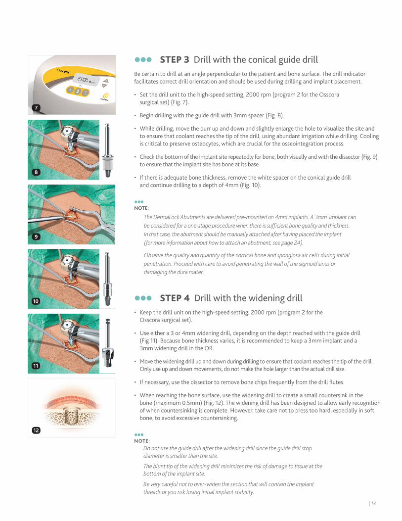
STEP 3 Drill with the conical guide drillBe certain to drill at an angle perpendicular to the patient and bone surface. The drill indicator facilitates correct drill orientation and should be used during drilling and implant placement.
• Set the drill unit to the high-speed setting, 2000 rpm (program 2 for the Osscora surgical set) (Fig. 7).
• Begin drilling with the guide drill with 3mm spacer (Fig. 8).
• While drilling, move the burr up and down and slightly enlarge the hole to visualize the site and to ensure that coolant reaches the tip of the drill, using abundant irrigation while drilling. Cooling is critical to preserve osteocytes, which are crucial for the osseointegration process.
• Check the bottom of the implant site repeatedly for bone, both visually and with the dissector (Fig. 9) to ensure that the implant site has bone at its base.
• If there is adequate bone thickness, remove the white spacer on the conical guide drill and continue drilling to a depth of 4mm (Fig. 10).
NOTE:
STEP 4 Drill with the widening drill• Keep the drill unit on the high-speed setting, 2000 rpm (program 2 for the
Osscora surgical set).
• Use either a 3 or 4mm widening drill, depending on the depth reached with the guide drill (Fig 11). Because bone thickness varies, it is recommended to keep a 3mm implant and a 3mm widening drill in the OR.
• Move the widening drill up and down during drilling to ensure that coolant reaches the tip of the drill. Only use up and down movements, do not make the hole larger than the actual drill size.
• If necessary, use the dissector to remove bone chips frequently from the drill flutes.
• When reaching the bone surface, use the widening drill to create a small countersink in the bone (maximum 0.5mm) (Fig. 12). The widening drill has been designed to allow early recognition of when countersinking is complete. However, take care not to press too hard, especially in soft bone, to avoid excessive countersinking.
NOTE:
Do not use the guide drill after the widening drill since the guide drill stop diameter is smaller than the site.
The blunt tip of the widening drill minimizes the risk of damage to tissue at the bottom of the implant site.
Be very careful not to over-widen the section that will contain the implant threads or you risk losing initial implant stability.
8
9
10
11
12
7
The DermaLock Abutments are delivered pre-mounted on 4mm implants. A 3mm implant can be considered for a one-stage procedure when there is sufficient bone quality and thickness. In that case, the abutment should be manually attached after having placed the implant (for more information about how to attach an abutment, see page 24).
Observe the quality and quantity of the cortical bone and spongiosa air cells during initial penetration. Proceed with care to avoid penetrating the wall of the sigmoid sinus or damaging the dura mater.
| 13
16
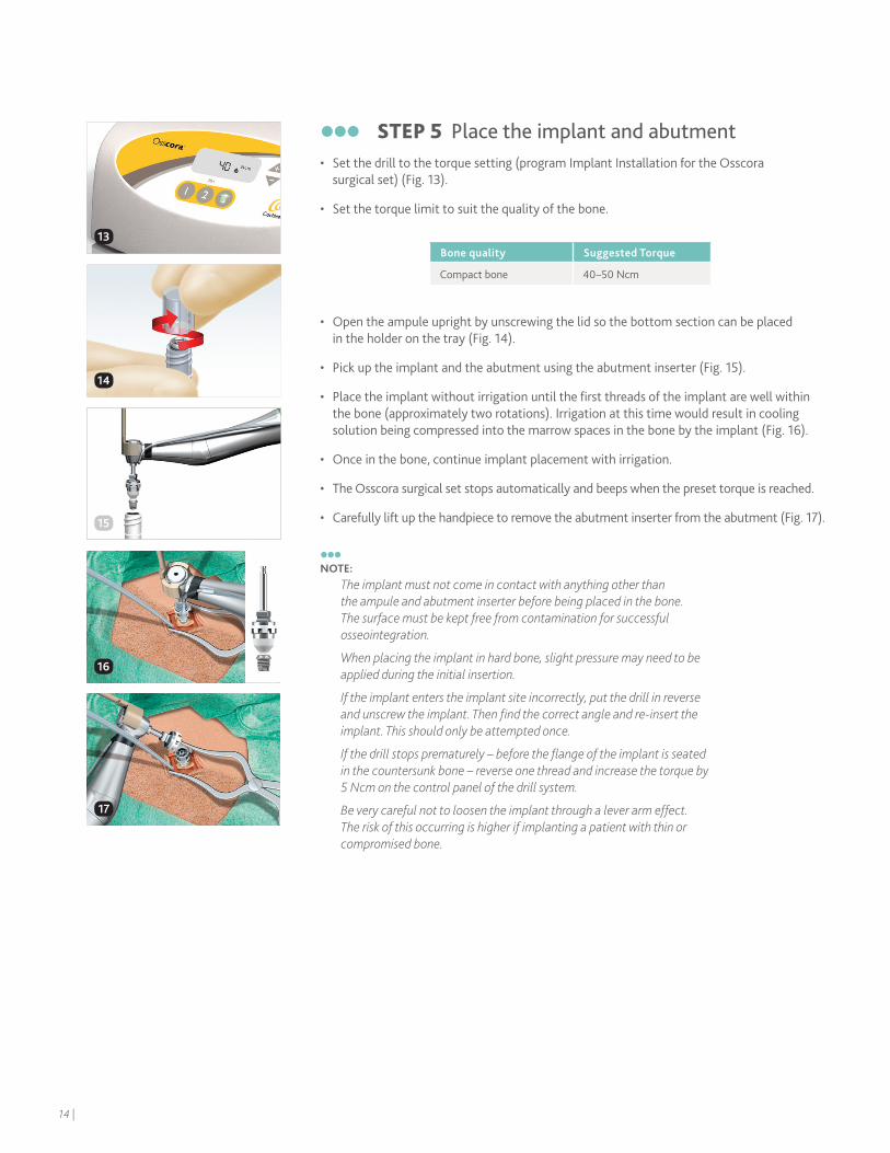
STEP 5 Place the implant and abutment• Set the drill to the torque setting (program Implant Installation for the Osscora
surgical set) (Fig. 13).
• Set the torque limit to suit the quality of the bone.
• Open the ampule upright by unscrewing the lid so the bottom section can be placed in the holder on the tray (Fig. 14).
• Pick up the implant and the abutment using the abutment inserter (Fig. 15).
• Place the implant without irrigation until the first threads of the implant are well within the bone (approximately two rotations). Irrigation at this time would result in cooling solution being compressed into the marrow spaces in the bone by the implant (Fig. 16).
• Once in the bone, continue implant placement with irrigation.
• The Osscora surgical set stops automatically and beeps when the preset torque is reached.
• Carefully lift up the handpiece to remove the abutment inserter from the abutment (Fig. 17).
NOTE:
The implant must not come in contact with anything other than the ampule and abutment inserter before being placed in the bone. The surface must be kept free from contamination for successful osseointegration.
When placing the implant in hard bone, slight pressure may need to be applied during the initial insertion.
If the implant enters the implant site incorrectly, put the drill in reverse and unscrew the implant. Then find the correct angle and re-insert the implant. This should only be attempted once.
If the drill stops prematurely – before the flange of the implant is seated in the countersunk bone – reverse one thread and increase the torque by 5 Ncm on the control panel of the drill system.
Be very careful not to loosen the implant through a lever arm effect. The risk of this occurring is higher if implanting a patient with thin or compromised bone.
Bone quality Suggested Torque
Compact bone 40 –50 Ncm
14
16
17
13
15
14 |
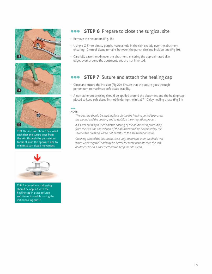
STEP 6 Prepare to close the surgical site• Remove the retractors (Fig. 18).
• Using a Ø 5mm biopsy punch, make a hole in the skin exactly over the abutment, ensuring 10mm of tissue remains between the punch site and incision line (Fig 19).
• Carefully ease the skin over the abutment, ensuring the approximated skin edges evert around the abutment, and are not inverted.
STEP 7 Suture and attach the healing cap• Close and suture the incision (Fig 20). Ensure that the suture goes through
periosteum to maximize soft tissue stability.
• A non-adherent dressing should be applied around the abutment and the healing cap placed to keep soft tissue immobile during the initial 7-10 day healing phase (Fig 21).
NOTE:
The dressing should be kept in place during the healing period to protect the wound and the coating and to stabilize the integration process.
If a silver dressing is used and the coating of the abutment is protruding from the skin, the coated part of the abutment will be discolored by the silver in the dressing. This is not harmful to the abutment or tissue.
Cleaning around the abutment site is very important. Non-alcoholic wet wipes work very well and may be better for some patients than the soft abutment brush. Either method will keep the site clean.
18
19
20
TIP: This incision should be closed such that the suture goes from the skin through the periosteum to the skin on the opposite side to minimize soft tissue movement.
TIP: A non-adherent dressing should be applied with the healing cap in place to keep soft tissue immobile during the initial healing phase.
| 15

16 |

Baha two-stage surgeryGenerally, two-stage surgery is recommended for patients with compromised or soft bone with a bone thickness less than 3mm. For children with bone thickness 3-4mm, factors such as patient age, developmental delay and bone quality may warrant the more conservative two-stage procedure.* The bone quality and thickness may also influence the length of the inter-stage interval and placement of a sleeper implant.
NOTE:
This section illustrates two-stage surgery with a straight incision. However, a skin flap may also be used.
When FAST surgery becomes a two-stage procedureBecause a FAST surgery may have to be converted to a two-stage surgery intra-operatively, it is recommended to keep a 3mm implant and a 3mm widening drill in the OR.
If a 4mm FAST system is being converted to a two stage procedure, disconnect the abutment from the implant by using the counter torque wrench and the 95mm Unigrip screwdriver. Place a cover screw into the implant at this time.
* In the U.S. and Canada, Baha surgery is indicated for children age five years and older.
| 17
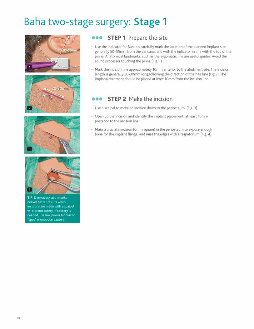
Baha two-stage surgery: Stage 1 STEP 1 Prepare the site • Use the indicator for Baha to carefully mark the location of the planned implant site,
generally 50–55mm from the ear canal and with the indicator in line with the top of the pinna. Anatomical landmarks, such as the zygomatic line are useful guides. Avoid the sound processor touching the pinna (Fig. 1).
• Mark the incision line approximately 10mm anterior to the abutment site. The incision length is generally 20-30mm long,following the direction of the hair line (Fig 2). The implant/abutment should be placed at least 10mm from the incision line.
STEP 2 Make the incision• Use a scalpel to make an incision down to the periosteum. (Fig. 3).
• Open up the incision and identify the implant placement, at least 10mm posterior to the incision line.
• Make a cruciate incision (6mm square) in the periosteum to expose enough bone for the implant flange, and raise the edges with a raspatorium (Fig. 4).
1
2
3
4
TIP: DermaLock abutments deliver better results when incisions are made with a scalpel vs. electrocautery. If cautery is needed, use low power bipolar or “spot” monopolar cautery.
18 |
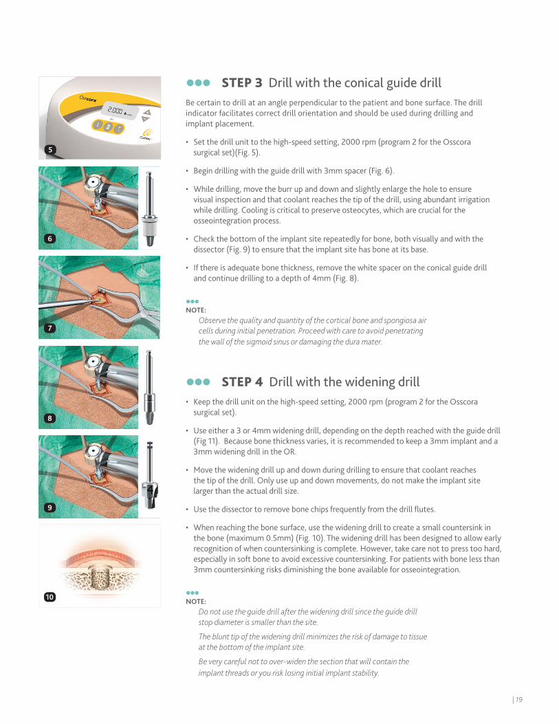
STEP 3 Drill with the conical guide drill Be certain to drill at an angle perpendicular to the patient and bone surface. The drill indicator facilitates correct drill orientation and should be used during drilling and implant placement.
• Set the drill unit to the high-speed setting, 2000 rpm (program 2 for the Osscora surgical set)(Fig. 5).
• Begin drilling with the guide drill with 3mm spacer (Fig. 6).
• While drilling, move the burr up and down and slightly enlarge the hole to ensure visual inspection and that coolant reaches the tip of the drill, using abundant irrigation while drilling. Cooling is critical to preserve osteocytes, which are crucial for the osseointegration process.
• Check the bottom of the implant site repeatedly for bone, both visually and with the dissector (Fig. 9) to ensure that the implant site has bone at its base.
• If there is adequate bone thickness, remove the white spacer on the conical guide drill and continue drilling to a depth of 4mm (Fig. 8).
NOTE:
Observe the quality and quantity of the cortical bone and spongiosa air cells during initial penetration. Proceed with care to avoid penetrating the wall of the sigmoid sinus or damaging the dura mater.
STEP 4 Drill with the widening drill • Keep the drill unit on the high-speed setting, 2000 rpm (program 2 for the Osscora
surgical set).
• Use either a 3 or 4mm widening drill, depending on the depth reached with the guide drill (Fig 11). Because bone thickness varies, it is recommended to keep a 3mm implant and a 3mm widening drill in the OR.
• Move the widening drill up and down during drilling to ensure that coolant reaches the tip of the drill. Only use up and down movements, do not make the implant site larger than the actual drill size.
• Use the dissector to remove bone chips frequently from the drill flutes.
• When reaching the bone surface, use the widening drill to create a small countersink in the bone (maximum 0.5mm) (Fig. 10). The widening drill has been designed to allow early recognition of when countersinking is complete. However, take care not to press too hard, especially in soft bone to avoid excessive countersinking. For patients with bone less than 3mm countersinking risks diminishing the bone available for osseointegration.
NOTE:
Do not use the guide drill after the widening drill since the guide drill stop diameter is smaller than the site.
The blunt tip of the widening drill minimizes the risk of damage to tissue at the bottom of the implant site.
Be very careful not to over-widen the section that will contain the implant threads or you risk losing initial implant stability.
6
7
8
9
10
5
| 19
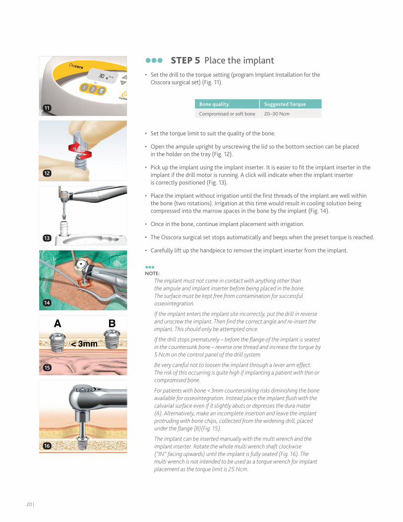
STEP 5 Place the implant • Set the drill to the torque setting (program Implant Installation for the
Osscora surgical set) (Fig. 11).
• Set the torque limit to suit the quality of the bone.
• Open the ampule upright by unscrewing the lid so the bottom section can be placed in the holder on the tray (Fig. 12).
• Pick up the implant using the implant inserter. It is easier to fit the implant inserter in the implant if the drill motor is running. A click will indicate when the implant inserter is correctly positioned (Fig. 13).
• Place the implant without irrigation until the first threads of the implant are well within the bone (two rotations). Irrigation at this time would result in cooling solution being compressed into the marrow spaces in the bone by the implant (Fig. 14).
• Once in the bone, continue implant placement with irrigation.
• The Osscora surgical set stops automatically and beeps when the preset torque is reached.
• Carefully lift up the handpiece to remove the implant inserter from the implant.
NOTE:
The implant must not come in contact with anything other than the ampule and implant inserter before being placed in the bone. The surface must be kept free from contamination for successful osseointegration.
If the implant enters the implant site incorrectly, put the drill in reverse and unscrew the implant. Then find the correct angle and re-insert the implant. This should only be attempted once.
If the drill stops prematurely – before the flange of the implant is seated in the countersunk bone – reverse one thread and increase the torque by 5 Ncm on the control panel of the drill system.
Be very careful not to loosen the implant through a lever arm effect. The risk of this occurring is quite high if implanting a patient with thin or compromised bone.
For patients with bone <3mm countersinking risks diminishing the bone available for osseointegration. Instead place the implant flush with the calvarial surface even if it slightly abuts or depresses the dura mater (A). Alternatively, make an incomplete insertion and leave the implant protruding with bone chips, collected from the widening drill, placed under the flange (B)(Fig. 15).
The implant can be inserted manually with the multi wrench and the implant inserter. Rotate the whole multi wrench shaft clockwise (“IN” facing upwards) until the implant is fully seated (Fig. 16). The multi wrench is not intended to be used as a torque wrench for implant placement as the torque limit is 25 Ncm.
Bone quality Suggested Torque
Compromised or soft bone 20 –30 Ncm
1212
15
16
14
11
20 |
13
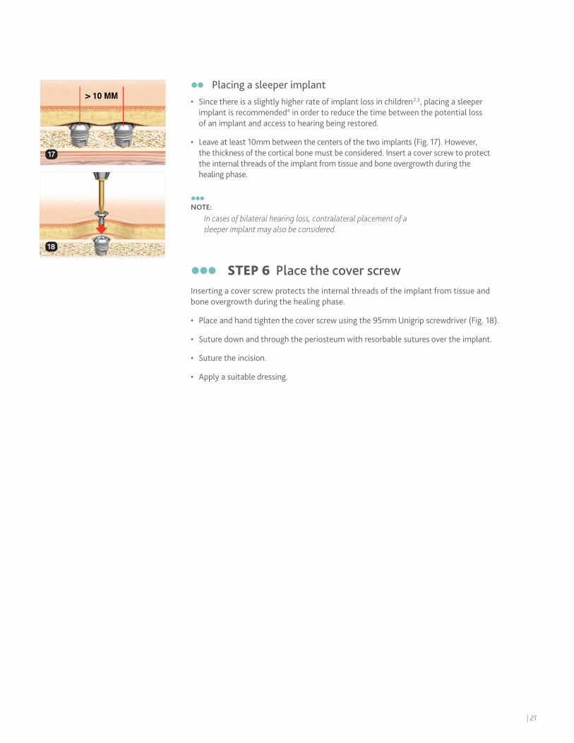
Placing a sleeper implant • Since there is a slightly higher rate of implant loss in children2,3, placing a sleeper
implant is recommended4 in order to reduce the time between the potential loss of an implant and access to hearing being restored.
• Leave at least 10mm between the centers of the two implants (Fig. 17). However, the thickness of the cortical bone must be considered. Insert a cover screw to protect the internal threads of the implant from tissue and bone overgrowth during the healing phase.
NOTE:
In cases of bilateral hearing loss, contralateral placement of a sleeper implant may also be considered.
STEP 6 Place the cover screwInserting a cover screw protects the internal threads of the implant from tissue and bone overgrowth during the healing phase.
• Place and hand tighten the cover screw using the 95mm Unigrip screwdriver (Fig. 18).
• Suture down and through the periosteum with resorbable sutures over the implant.
• Suture the incision.
• Apply a suitable dressing.
18
17
| 21
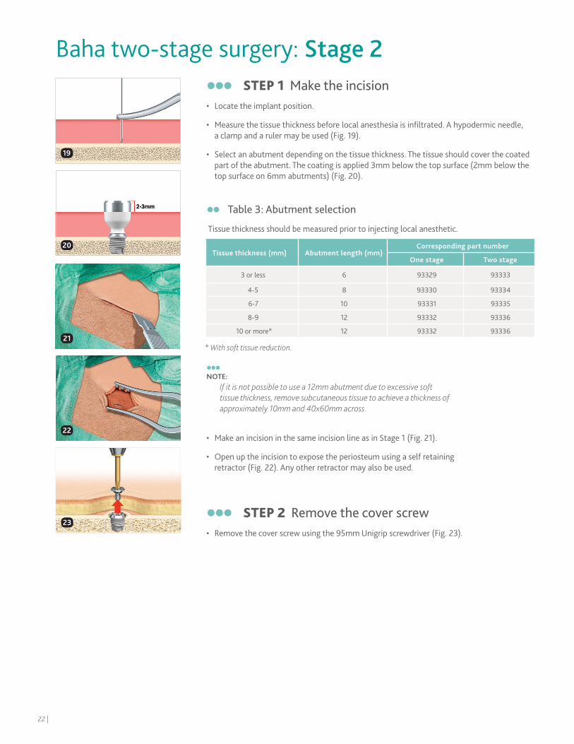
STEP 1 Make the incision • Locate the implant position.
• Measure the tissue thickness before local anesthesia is infiltrated. A hypodermic needle, a clamp and a ruler may be used (Fig. 19).
• Select an abutment depending on the tissue thickness. The tissue should cover the coated part of the abutment. The coating is applied 3mm below the top surface (2mm below the top surface on 6mm abutments) (Fig. 20).
NOTE:
If it is not possible to use a 12mm abutment due to excessive soft tissue thickness, remove subcutaneous tissue to achieve a thickness of approximately 10mm and 40x60mm across.
• Make an incision in the same incision line as in Stage 1 (Fig. 21).
• Open up the incision to expose the periosteum using a self retaining retractor (Fig. 22). Any other retractor may also be used.
STEP 2 Remove the cover screw• Remove the cover screw using the 95mm Unigrip screwdriver (Fig. 23).
Baha two-stage surgery: Stage 2
19
20
21
22
23
Table 3: Abutment selection
Tissue thickness should be measured prior to injecting local anesthetic.
Tissue thickness (mm) Abutment length (mm)Corresponding part number
One stage Two stage
3 or less 6 93329 93333
4-5 8 93330 93334
6-7 10 93331 93335
8-9 12 93332 93336
10 or more* 12 93332 93336
* With soft tissue reduction.
22 |
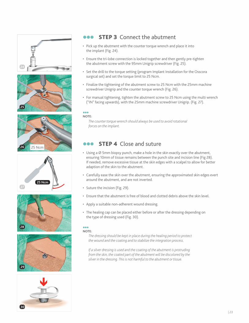
STEP 3 Connect the abutment • Pick up the abutment with the counter torque wrench and place it into
the implant (Fig. 24).
• Ensure the tri-lobe connection is locked together and then gently pre-tighten the abutment screw with the 95mm Unigrip screwdriver (Fig. 25).
• Set the drill to the torque setting (program Implant Installation for the Osscora surgical set) and set the torque limit to 25 Ncm.
• Finalize the tightening of the abutment screw to 25 Ncm with the 25mm machine screwdriver Unigrip and the counter torque wrench (Fig. 26).
• For manual tightening, tighten the abutment screw to 25 Ncm using the multi wrench (“IN” facing upwards), with the 25mm machine screwdriver Unigrip. (Fig. 27).
NOTE:
The counter torque wrench should always be used to avoid rotational forces on the implant.
STEP 4 Close and suture• Using a Ø 5mm biopsy punch, make a hole in the skin exactly over the abutment,
ensuring 10mm of tissue remains between the punch site and incision line (Fig 28). If needed, remove excessive tissue at the skin edges with a scalpel to allow for better adaption of the skin to the abutment.
• Carefully ease the skin over the abutment, ensuring the approximated skin edges evert around the abutment, and are not inverted.
• Suture the incision (Fig. 29).
• Ensure that the abutment is free of blood and clotted debris above the skin level.
• Apply a suitable non-adherent wound dressing.
• The healing cap can be placed either before or after the dressing depending on the type of dressing used (Fig. 30).
NOTE:
The dressing should be kept in place during the healing period to protectthe wound and the coating and to stabilize the integration process.
If a silver dressing is used and the coating of the abutment is protruding from the skin, the coated part of the abutment will be discolored by the silver in the dressing. This is not harmful to the abutment or tissue.
24
25
24
27
28
29
25 Ncm26
25 Ncm
30
Table 3: Abutment selection
Tissue thickness should be measured prior to injecting local anesthetic.
| 23
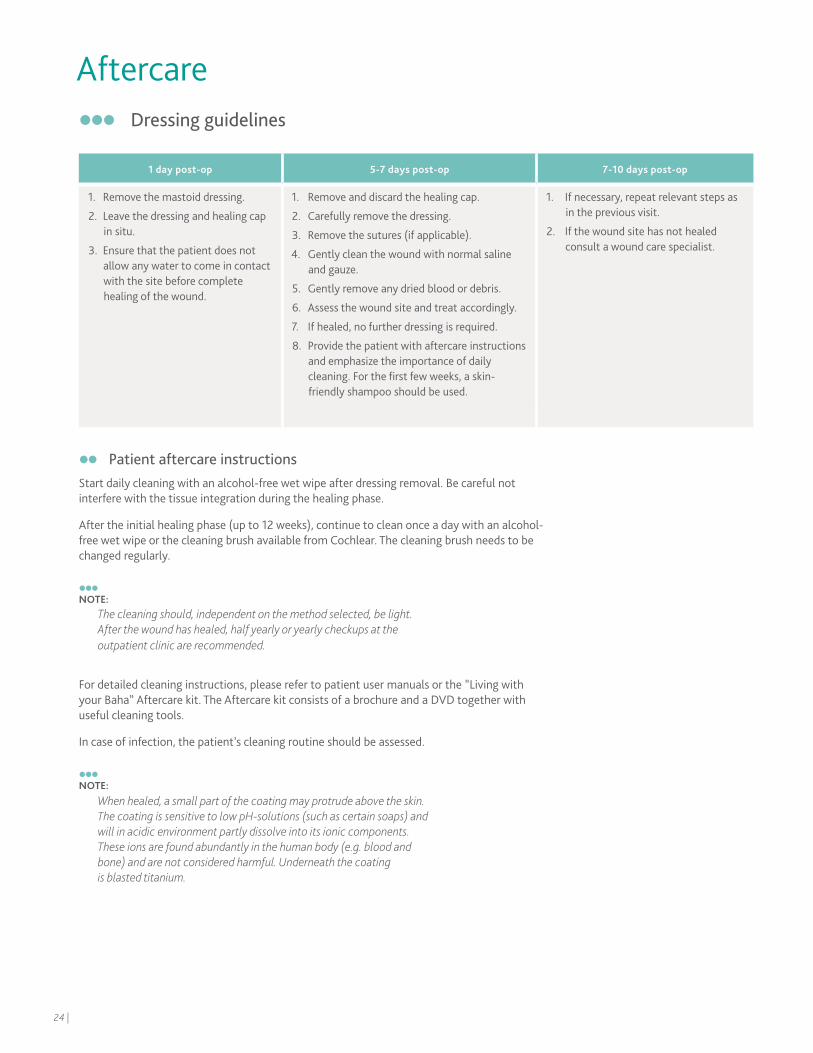
Aftercare Dressing guidelines
Patient aftercare instructionsStart daily cleaning with an alcohol-free wet wipe after dressing removal. Be careful not interfere with the tissue integration during the healing phase.
After the initial healing phase (up to 12 weeks), continue to clean once a day with an alcohol-free wet wipe or the cleaning brush available from Cochlear. The cleaning brush needs to be changed regularly.
NOTE:
The cleaning should, independent on the method selected, be light. After the wound has healed, half yearly or yearly checkups at the outpatient clinic are recommended.
For detailed cleaning instructions, please refer to patient user manuals or the ”Living with your Baha” Aftercare kit. The Aftercare kit consists of a brochure and a DVD together with useful cleaning tools.
In case of infection, the patient’s cleaning routine should be assessed.
NOTE:
When healed, a small part of the coating may protrude above the skin. The coating is sensitive to low pH-solutions (such as certain soaps) and will in acidic environment partly dissolve into its ionic components. These ions are found abundantly in the human body (e.g. blood and bone) and are not considered harmful. Underneath the coating is blasted titanium.
1 day post-op 5-7 days post-op 7-10 days post-op
1. Remove the mastoid dressing.
2. Leave the dressing and healing cap in situ.
3. Ensure that the patient does not allow any water to come in contact with the site before complete healing of the wound.
1. Remove and discard the healing cap.
2. Carefully remove the dressing.
3. Remove the sutures (if applicable).
4. Gently clean the wound with normal saline and gauze.
5. Gently remove any dried blood or debris.
6. Assess the wound site and treat accordingly.
7. If healed, no further dressing is required.
8. Provide the patient with aftercare instructions and emphasize the importance of daily cleaning. For the first few weeks, a skin-friendly shampoo should be used.
1. If necessary, repeat relevant steps as in the previous visit.
2. If the wound site has not healed consult a wound care specialist.
24 |
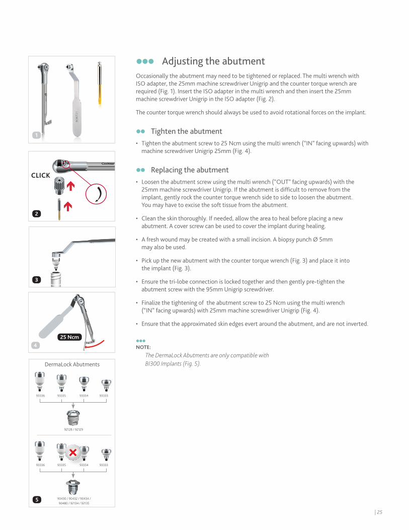
Adjusting the abutmentOccasionally the abutment may need to be tightened or replaced. The multi wrench with ISO adapter, the 25mm machine screwdriver Unigrip and the counter torque wrench are required (Fig. 1). Insert the ISO adapter in the multi wrench and then insert the 25mm machine screwdriver Unigrip in the ISO adapter (Fig. 2).
The counter torque wrench should always be used to avoid rotational forces on the implant.
Tighten the abutment• Tighten the abutment screw to 25 Ncm using the multi wrench (“IN” facing upwards) with
machine screwdriver Unigrip 25mm (Fig. 4).
Replacing the abutment• Loosen the abutment screw using the multi wrench (“OUT” facing upwards) with the
25mm machine screwdriver Unigrip. If the abutment is difficult to remove from the implant, gently rock the counter torque wrench side to side to loosen the abutment. You may have to excise the soft tissue from the abutment.
• Clean the skin thoroughly. If needed, allow the area to heal before placing a new abutment. A cover screw can be used to cover the implant during healing.
• A fresh wound may be created with a small incision. A biopsy punch Ø 5mm may also be used.
• Pick up the new abutment with the counter torque wrench (Fig. 3) and place it into the implant (Fig. 3).
• Ensure the tri-lobe connection is locked together and then gently pre-tighten the abutment screw with the 95mm Unigrip screwdriver.
• Finalize the tightening of the abutment screw to 25 Ncm using the multi wrench (“IN” facing upwards) with 25mm machine screwdriver Unigrip (Fig. 4).
• Ensure that the approximated skin edges evert around the abutment, and are not inverted.
NOTE:
The DermaLock Abutments are only compatible with BI300 Implants (Fig. 5).
2
4
DermaLock Abutments
93333 93335 9333493336
93333 93335 9333493336
92128 / 92129
5 90430 / 90432 / 90434 / 90480 / 92134 / 92135
25 Ncm
CLICK
3
1
| 25
Complications The success rate for Baha surgery is very high. However, unexpected situations, both intra-operatively and postoperatively, may occur. Below is a list of potential complications and recommendations for handling them. Importantly, the patient must be informed of all possible complications related to safety and effectiveness prior to surgery.The regulation of medical devices requires the manufacturer to report adverse events to the appropriate authority. Should such an incident occur, notify your local Cochlear office or its official distributor as soon as possible.
Complications during surgery
Implant becomes stuck during insertionThis can occur if the implant alignment is incorrect. Set the drill unit to reverse mode. Then unscrew the implant. Find the correct alignment and re-insert the implant. If the same happens again, prepare a new implant site at least 10mm from the first site.
Implant continues to rotate when seatedThis may occur when drilling in compromised and soft bone, and when the torque is set too high in relation to the quality of the bone. Prepare a new implant site at least 10mm from the first site and then place the implant with a lower torque.
Exposure of dura mater or perforation of the sigmoid sinusAlthough rare, a mild CSF or blood leak can occur during guide hole drilling. If this occurs, it is a low pressure system that can be sealed easily. If there is good bone volume, place the implant to seal the leak. If the bone is too thin, seal the leak with soft tissue of bone wax. Then choose a new implant site at least 10mm from the original site (as close as possible without intersecting).
Subdural hematomaThis condition, caused by venous bleeding under the dura, is rare and typically slow developing. It is not often identified during surgery, but is more likely caused by direct trauma and will develop gradually over time and display general neurological symptoms. Should this occur, a CT or MRI can be used to verify the diagnosis. Treat this condition according to general practice.
26 |
Post-operative soft tissue complications
Inflammation and infection around the abutmentPoor or excessive personal hygiene is the most common cause of irritation. It could also be due to a loose abutment or insufficient osseointegration.
If the skin around the abutment becomes inflamed /infected, thoroughly clean the entire implant site and, if appropriate, apply antimicrobial cream. Provide the patient with the appropriate aftercare instructions.
If further treatment is needed, an antibiotic/steroid injection might be considered.
Persistent soft tissue complicationsWhen medical therapy has failed and the patient has a persistent problem, remove the abutment. You may have to excise the soft tissue from the abutment. Clean the skin thoroughly. Perform a culture before providing the appropriate antimicrobial and anti-inflammatory treatment. Place a cover screw and allow the area to heal before placing a new abutment. Ensure the approximated skin edges evert around the abutment, and are not inverted.
Skin overgrowth
In some patients (predominantly male teenagers) an inflammatory reaction may occur and result in soft tissue thickening or complete overgrowth of the abutment by soft tissue. Treatment with a longer abutment, topical steroid cream or a steroid injection may be consideared. 7,8
KeloidsIn the case of keloids that do not subside over time, an injection with Kenalog might be considered. Another option is to place a silicone disc9 over the keloid and keep pressure on the silicone disc for 7-10 days.
Post-operative numbness-parasthesiaPostoperative numbness may occur. Usually this will subside after a few months.
| 27
Post-operative bone complications
Implant lossPotential causes for failure of osseointegration include lack of adequate bone quantity/quality, trauma, infection, generalized diseases and surgical complications.
Bony overgrowthThe potential for a bony overgrowth around the implant is highest in children implanted at a very young age. Removal of some bone will allow sufficient clearance between the skin and the Baha sound processor.
Pain when touching the abutmentIf the patient experiences pain when touching the abutment, there may be an increased risk of implant loss. In most cases, the loose implant can be removed and another one placed in adjacent bone. In others, the implant must be removed and the defect then carefully curetted and filled with blood coagulates. In most cases adjacent bone is available and suitable for the placement of another implant.
Special considerations
MRI and magnetic fieldsBe certain to caution patients about procedures that could be harmful to the sound processor, such as MRI and other magnetic fields. Always remove the sound processor before an MRI procedure. The implant itself and the abutment are not ferromagnetic and will not cause any damage to the patient during an MRI.10 The resulting artifacts are minor.
Radiation therapyIf a patient already has an implant, and is scheduled for radiation therapy around the implant area, the abutment should be removed but the implant could be left in place to allow healing of the site before radiation is performed. A cover screw can be used to cover the implant until the abutment is replaced.
Sporting activitiesIt is important to educate the parents and caregivers about the need for helmets and other safety precautions during sporting activities to minimize traumatic events. Traumatic implant loss can still occur across all age groups.
28 |
1. Snik AF, Mylanus EA, Proops DW, Wolfaardt JF, Hodgetts WE, Somers T, Niparko JK, Wazen JJ, Sterkers O, Cremers CW, Tjellström A. Consensus statements on the BAHA system: where do we stand at present? Ann Otol Rhinol Laryngol Suppl. 2005 Dec;195:2-12.
2. de Wolf MJ et al. Nijmegen results with application of a Bone-Anchored Hearing Aid in children: Simplified Surgical Technique Ann Otol Rhinol Laryngol. 2008;117(11):805-14.
3. McDermott AL, Williams J, Kuo M, Reid A, Proops D, The Birmingham paediatric bone anchored hearing aid programme: A 15 year experience . Otol Neurotol. 2009;30(2):178-83.
4. Durvasula VS, Patel H, Mahendran S, Gray RF. Bone anchored hearing aids: a second fixture reduces auditory deprivation in Cambridge. Eur Arch Otorhinolaryngol. 2007 Sep;264(9):991-4.
5. Priwin C, Stenfelt S, Granström G, Tjellström A, Håkansson B. Bilateral Bone-Anchored Hearing Aids (BAHAs): an audiometric evaluation. The Laryngoscope 2004;114(1):77-84.
6. Eeg-Olofsson M, Stenfelt S, Tjellström A, Granström G. Transmission of bone-conducted sound in the human skull measured by cochlear vibrations. Int J Audiol. 2008 Dec;47(12):761-9.
7. Falcone MT, Kaylie DM, Labadie RF, Haynes DS. Bone-anchored hearing aid abutment skin overgrowth reduction with clobetasol. Otolaryngol Head Neck Surg. 2008 Dec;139(6):829-32.
8. Ghossaini SN, Spitzer JB. Local steroid injections in the management of skin growth over the abutment in Baha patients. Otolaryngol Head Neck Surg. 2009 Oct;141(4):530-2.
9. Wiseman S, Tapia G, Schaaf N, Sullivan M, Loree T. Utilization of a plastic washer to prevent auricular prosthesis abutment overgrowth report of a case and description of a technique. International Journal of Oraland Maxillofacial Implants 2001 Nov-Dec;16(6):880-82
10. Arndt S, Kromeier J, Berlis A, Maier W, Laszig R, Aschendorff, A. Imaging procedures after bone-anchored hearing aid, implantation. Laryngoscope; 2007, Oct;117(10):1815–8
References
Products in this manual are protected by the following patents: US 5 735 790, US 5 935 170, EP 0715839, EP 0715838, US 07074222, WO 02/09622, US 7409070, EB 01633284, US 27009853, WO 04105650 , US 2010249784 (A1) and corresponding patents in other countries and pending patent applications. All products can be subject to change without notice. No part of this publication may be replaced, stored in a retrieval system, or transmitted, in any form by means, electronic, mechanical, photocopying, recording or otherwise, without the prior written permission of the publisher.
| 29

Notes
30 |

Notes
| 31
As the leading global expert in implantable hearing solutions, Cochlear is dedicated to bringing the gift of sound to people all over the world. For thirty years, Cochlear has pioneered this technology, helping more than a quarter of a million people reconnect to their families and friends.
Along with the industry’s largest investment in research and development, we continue to partner with leading international researchers and hearing professionals, ensuring that we are at the forefront of hearing science.
For our customers, that means access to our latest technologies throughout their lives, and the ongoing support they need.
That is why seven out of ten people worldwide who choose a cochlear implant choose Cochlear as their hearing partner.*
©Cochlear Limited 2014. All rights reserved. Hear now. And always and other trademarks and registered trademarks are the property of Cochlear Limited or Cochlear Bone Anchored Solutions AB. The names of actual companies and products mentioned herein may be the trademarks of their respective owners.
BUN128 ISS2 AUG14
Cochlear Americas 13059 East Peakview Avenue Centennial, CO 80111 USA Telephone: 1 303 790 9010 Support: 1 800 483 3123
Cochlear Canada Inc. 2500-120 Adelaide Street West Toronto, ON M5H 1T1 Canada Telephone: 1 416 972 5082 Fax: 1 416 972 5083
www.Cochlear.com/US Follow us on
*Cochlear Americas [Data on file] 2012 March.
Not everyone with hearing loss is a candidate for a Baha. All surgical procedures include an element of risk, and it is impossible to guarantee success. For complete information regarding the risks and benefits of a Baha procedure, please refer to the Instructions for use for the Baha implant available at www.Cochlear.com/US/BahaIndications