Baffle and Shredder Kits - Land Pride · The Baffle Kit and Shredder Kit are exclusively ... 5020...
12
1 © Copyright 2010 Printed Before You Start The Baffle Kit and Shredder Kit are exclusively designed for your 20’ Land Pride Rotary Cutter. Please read these installation instructions and your Rotary Cutter Operator’s Manual thoroughly before beginning. Especially read information relating to safety concerns. Also included in the Operator’s Manual is important information on operation, adjustment, troubleshooting, and maintenance for this attachment (some manual sections do not apply to all accessories). A separate Rotary Cutter Parts Manual is available free of charge at www.landpride.com or can be purchased from your nearest Land Pride dealer. Have the model and serial numbers of your cutter handy when placing an order. Manual Part Numbers: • Operator’s Manual . . . . . . . . . . . . . . . . . 318-474M • Parts Manual . . . . . . . . . . . . . . . . . . . . . 318-474P General Information These assembly instructions apply to the Baffle and Shredder Kits listed below: 330-309A SHREDDER/FIXED BLADE/BAFFLE 330-114A BAFFLES, FRONT 330-308A SHREDDER/FIXED BLADE 330-585A BAFFLES, REAR Tools required: • Safety Glasses • Work Gloves • Two 3/4" wrenches . . . . . . . . . . . . . . . . . Baffle Kit Only • Two 1 1/2" wrenches . . . . . . . . . . . . Shredder Kit Only • One 55mm wrench . . . . . . . . . . . . . . Shredder Kit Only When you see this symbol, the subsequent instructions and warnings are serious - follow without exception. Your life and the lives of others depend on it! ! IMPORTANT: Before you begin, read these instructions and check to be sure all parts and tools are accounted for. Please retain these installation instructions for future reference and parts ordering information. Further Assistance Your dealer wants you to be satisfied with your new Baffle and Shredder Kits. If for any reason you do not understand any part of this manual or are not satisfied with the service received, the following actions are suggested: 1. Discuss the matter with your dealership service manager making sure he is aware of any problems you may have and that he has had the opportunity to assist you. 2. If you are still not satisfied, seek out the owner or general manager of the dealership, explain the problem and request assistance. 3. For further assistance write to: Land Pride Service Department 1525 East North Street P.O. Box 5060 Salina, Ks. 67402-5060 E-mail address [email protected] Safety Information ! DANGER Always disconnect main driveline from tractor PTO before servicing cutter deck. Cutter can be engaged if tractor is started resulting in cutter damage, bodily injury and/or death. ! WARNING Never work under equipment supported by hydraulics. Hydraulics can drop equipment if controls are actuated or if hydraulic lines burst. Either situation can drop the cutter instantly even when power to the hydraulics is shut off. Assembly Instructions A detailed listing of parts for the Baffle and Shredder Kits is provided on pages 10 & 11. Use the list as a checklist to inventory parts received. Please contact your local Land Pride dealer for any missing hardware. 1. Cutters with Serial No. 536742 and lower: Lower cutter and wings to the lowest position. Cutters with Serial No. 536743 and above: Raise wings fully up and lock into position with transport locks. IMPORTANT: Read all "Safety Information" above before working on and around the cutter decks. For RC(M)5020 Rotary Cutters Baffle and Shredder Kits 3/11/10 Manual No. 330-148M
Transcript of Baffle and Shredder Kits - Land Pride · The Baffle Kit and Shredder Kit are exclusively ... 5020...

1© Copyright 2010 Printed
Before You Start
The Baffle Kit and Shredder Kit are exclusively designedfor your 20’ Land Pride Rotary Cutter. Please read theseinstallation instructions and your Rotary CutterOperator’s Manual thoroughly before beginning.Especially read information relating to safety concerns.Also included in the Operator’s Manual is importantinformation on operation, adjustment, troubleshooting,and maintenance for this attachment (some manualsections do not apply to all accessories).
A separate Rotary Cutter Parts Manual is available freeof charge at www.landpride.com or can be purchasedfrom your nearest Land Pride dealer. Have the modeland serial numbers of your cutter handy when placing anorder.
Manual Part Numbers:• Operator’s Manual . . . . . . . . . . . . . . . . . 318-474M
• Parts Manual . . . . . . . . . . . . . . . . . . . . . 318-474P
General InformationThese assembly instructions apply to the Baffle andShredder Kits listed below:
330-309A SHREDDER/FIXED BLADE/BAFFLE330-114A BAFFLES, FRONT330-308A SHREDDER/FIXED BLADE330-585A BAFFLES, REAR
Tools required:• Safety Glasses• Work Gloves• Two 3/4" wrenches . . . . . . . . . . . . . . . . .Baffle Kit Only• Two 1 1/2" wrenches . . . . . . . . . . . . Shredder Kit Only• One 55mm wrench . . . . . . . . . . . . . . Shredder Kit Only
When you see this symbol, the subsequentinstructions and warnings are serious - followwithout exception. Your life and the lives ofothers depend on it!
!
IMPORTANT: Before you begin, read theseinstructions and check to be sure all parts and toolsare accounted for. Please retain these installationinstructions for future reference and parts orderinginformation.
Further AssistanceYour dealer wants you to be satisfied with your newBaffle and Shredder Kits. If for any reason you do notunderstand any part of this manual or are not satisfiedwith the service received, the following actions aresuggested:
1. Discuss the matter with your dealership servicemanager making sure he is aware of any problemsyou may have and that he has had the opportunity toassist you.
2. If you are still not satisfied, seek out the owner orgeneral manager of the dealership, explain theproblem and request assistance.
3. For further assistance write to:
Land Pride Service Department1525 East North Street
P.O. Box 5060Salina, Ks. 67402-5060
E-mail [email protected]
Safety Information
! DANGERAlways disconnect main driveline from tractor PTO beforeservicing cutter deck. Cutter can be engaged if tractor isstarted resulting in cutter damage, bodily injury and/or death.
! WARNINGNever work under equipment supported by hydraulics.Hydraulics can drop equipment if controls are actuated or ifhydraulic lines burst. Either situation can drop the cutterinstantly even when power to the hydraulics is shut off.
Assembly Instructions
A detailed listing of parts for the Baffle and Shredder Kitsis provided on pages 10 & 11. Use the list as a checklistto inventory parts received. Please contact your localLand Pride dealer for any missing hardware.
1. Cutters with Serial No. 536742 and lower:Lower cutter and wings to the lowest position.
Cutters with Serial No. 536743 and above:Raise wings fully up and lock into position withtransport locks.
IMPORTANT: Read all "Safety Information" abovebefore working on and around the cutter decks.
For RC(M)5020 Rotary Cutters
Baffle and Shredder Kits
3/11/10
Manual No. 330-148M

2 Manual No. 330-148M 3/11/10
Assembly Instructions
Bolt Hole Pattern (Left Wing Shown)Figure 1

33/11/10 Manual No. 330-148M
Assembly Instructions
Baffle Installation (Left Wing Shown)Figure 2
Refer to Figure 1 on page 2:1. Locate and drill twelve 9/16" dia. holes on each wing
deck as shown in Figure 1. If holes already exist, skipto step 2 below.
Refer to Figure 2:2. The wings should be raised and locked into position
for the remainder of the assembly.
3. Attach four front baffles (#1) to the left-hand wingdeck with 1/2"-13 x 1 1/2" GR5 hex head bolts (#2),1/2" flat washers (#4) and 1/2" hex whiz nut (#3).
4. Tighten nuts to 76 ft-lbs of torque.
5. Repeat steps 3 & 4 for the right-hand wing deck.
NOTE: Drilling holes is not necessary on modelsmanufactured after Serial No. 536742. Skip tostep 2 below if cutter Serial No. is 536743 or higher.
2. Place tractor gear selector in park and/or set brakes,shut engine off and remove ignition key.
3. Disconnect main driveline from tractor PTO.
Shredder/Fixed Blade/Baffle KitKit No. 330-309AThis Kit consist of Kits 330-114A and 330-308A.Therefore, see Kit No. 330-114A below for assemblyinstructions of the front baffles and Kit No. 330-308A onpage 4 for assembly instructions of the shredder bladesand fixed blades.
Front Baffle KitKit No. 330-114AA detailed listing of parts for this accessory kit is providedon page 10. Use the list as a checklist to inventory partsreceived. Please contact your local Land Pride dealer forany missing hardware.

4 Manual No. 330-148M 3/11/10
Assembly Instructions
Shredder/Fixed Blade KitKit No. 330-308AA detailed listing of parts for this accessory kit is providedon page 11. Use the list as a checklist to inventory partsreceived. Please contact your local Land Pride dealer forany missing hardware.
Refer to Figure 3 & Figure 4:1. Remove all three existing blade carrier assemblies
(not shown) from the gearbox output shafts (A & B).Keep flat washers (C), slotted hex nuts (D) and cotterpins (E) for reuse.
Right Wing Shredder Assembly(Part No. 330-228S)Refer to Figure 3:1. Attach right wing shredder assembly (#1) to gearbox
output shaft (A) with existing washer (C) and slottedhex nut (D). Torque slotted nut to 550 ft./lbs.
2. Install cotter pin (E) in the slotted nut and throughoutput shaft (A). Secure cotter pin (E) by bending itslegs around the nut.
Center Deck & Left Wing Shredder Assembly(Part No’s. 330-302S)Refer to Figure 4:1. Attach center deck and left wing shredder
assemblies (#2) to gearbox output shafts (B) withexisting washer (C) and slotted hex nut (D). Torqueslotted nut to 550 ft./lbs.
2. Install cotter pin (E) in the slotted nut and throughoutput shaft (B). Secure cotter pin (E) by bending itslegs around the nut.
IMPORTANT: Read “Safety Information” on page 1before installing shredder blades.
Right Wing Shredder Assembly (P/N 330-228S)Figure 3
Center Deck Shredder Assembly (P/N 330-302S)And Left Wing Shredder Assembly (P/N 330-302S)
Figure 4
Clockwise Rotation 25601
Counterclockwise Rotation25601

53/11/10 Manual No. 330-148M
Assembly Instructions
Check Free Vertical Movement of BladesRefer to Figure 5:The cutting blades should not have more than 3/4" freevertical movement at the blade tips. If vertical movementexceeds 3/4", install or change to thicker spacers (#3)following steps 1 through 5.
Order spacers (#3) and locknuts (#7) from your nearestLand Pride Dealer.
IMPORTANT: Read “Safety Information” on page 1before disassembling the shredder blades.
IMPORTANT: Locknuts can lose their ability to lockproperly once removed. Always use a plainthrowaway nut during pre-assembly of spacers.
IMPORTANT: Spacers (#3) are not required ifvertical movement at blade tip is 3/4" or less withoutspacers. However, spacers are required if verticalmovement at blade tip is greater than 3/4". This isparticularly important when using fixed blades.
1. Check blade deflection. If vertical deflection at theblade tip is greater than 3/4", remove blade bolt (#6)and reassemble using thicker spacers (#3). Selectspacer thickness based on deflection. The greaterthe deflection, the thicker the spacer required.
2. Assemble blades by inserting 1"-8 x 4 1/2" GR8 hexhead bolt (#6) through blade bushing (#4),spacer (#3), lower cutting blade (#8 or #10), bladecarrier (#5), upper flat cutting blade (#9), spacer (#3)and blade bushings (#4). Temporary secure bladewith a plain hex nut (Plain hex nut furnished bycustomer.) Draw nut up snug. Do not tighten.
3. Check blade deflection. If deflection at the blade tipsare greater than 3/4", remove blade bolt andreassemble as before with thicker spacers.
4. Once blade deflection is correct, replace plain nutwith supplied locknut (#7) & torque to 450 ft-lbs.
5. Repeat "Check Free Vertical Movement of Blades"instructions for the remaining shredder bladeassemblies.
Figure 5
(#1) Right Wing Shredder AssemblyClockwise Rotation (P/N 330-228S)
(#2) Center Deck & Left Wing Shredder AssembliesCounterclockwise Rotation (P/N 330-302S)
Blade Cutting EdgesPosition Beveled Edges Up
CCWRotation
BladeCuttingEdge
BladeCuttingEdge
CWRotation
Position BeveledEdges Down
25600

6 Manual No. 330-148M 3/11/10
Assembly Instructions
Fixed Blade Mounting HolesRefer to Figure 6:The bolt holes for mounting fixed blades to the wingdecks are not included on earlier models. See location ofmounting holes below to determine if your cutter has themounting holes. If mounting holes are present, skip to“Center Deck Fixed Blade Assembly” on page 7. Ifholes are missing, add them to the deck as follows:
1. Locate and drill four 9/16" dia. holes on the left wingdeck as shown in Figure 1.
2. Repeat step 1 above for the right wing deck.
Bolt Hole Pattern For Mounting Fixed Blades On The Wings (Left Wing ShownFigure 6
30182
73/11/10 Manual No. 330-148M
Assembly Instructions
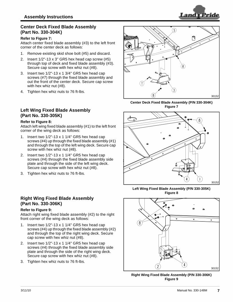
Center Deck Fixed Blade Assembly(Part No. 330-304K)Refer to Figure 7:Attach center fixed blade assembly (#3) to the left frontcorner of the center deck as follows:
1. Remove existing skid shoe bolt (#5) and discard.
2. Insert 1/2"-13 x 3" GR5 hex head cap screw (#5)through top of deck and fixed blade assembly (#3).Secure cap screw with hex whiz nut (#8).
3. Insert two 1/2"-13 x 1 3/4" GR5 hex head capscrews (#7) through the fixed blade assembly andout the front of the center deck. Secure cap screwwith hex whiz nut (#8).
4. Tighten hex whiz nuts to 76 ft-lbs.
Left Wing Fixed Blade Assembly(Part No. 330-305K)Refer to Figure 8:Attach left wing fixed blade assembly (#1) to the left frontcorner of the wing deck as follows:
1. Insert two 1/2"-13 x 1 1/4" GR5 hex head capscrews (#4) up through the fixed blade assembly (#1)and through the top of the left wing deck. Secure capscrew with hex whiz nut (#8).
2. Insert two 1/2"-13 x 1 1/4" GR5 hex head capscrews (#4) through the fixed blade assembly sideplate and through the side of the left wing deck.Secure cap screw with hex whiz nut (#8).
3. Tighten hex whiz nuts to 76 ft-lbs.
Right Wing Fixed Blade Assembly(Part No. 330-306K)Refer to Figure 9:Attach right wing fixed blade assembly (#2) to the rightfront corner of the wing deck as follows:
1. Insert two 1/2"-13 x 1 1/4" GR5 hex head capscrews (#4) up through the fixed blade assembly (#2)and through the top of the right wing deck. Securecap screw with hex whiz nut (#8).
2. Insert two 1/2"-13 x 1 1/4" GR5 hex head capscrews (#4) through the fixed blade assembly sideplate and through the side of the right wing deck.Secure cap screw with hex whiz nut (#8).
3. Tighten hex whiz nuts to 76 ft-lbs.
Center Deck Fixed Blade Assembly (P/N 330-304K)Figure 7
Left Wing Fixed Blade Assembly (P/N 330-305K)Figure 8
Right Wing Fixed Blade Assembly (P/N 330-306K)Figure 9
301523015
30152
30152

8 Manual No. 330-148M 3/11/10
Assembly Instructions
Rear Baffle KitKit No. 330-585AA detailed listing of parts for this accessory kit is providedon page 11. Use the list as a checklist to inventory partsreceived. Please contact your local Land Pride dealer forany missing hardware.
Right Rear Baffle Assembly(Part No. 330-620K)Refer to Figure 10:1. Locate right-hand rear baffle (#19). It is the baffle
with mounting plate extending pass the deflector onthe right side as shown. The mounting plate is flushwith the deflector on the left side.
2. Install right-hand rear baffle (#19) at the back of theright wing deck by inserting 1/2"-13 x 1 1/2" GR5round-head, square-neck bolts (#23) through thedeck’s rear curved plate first and then through therear baffle mounting plate as shown.
3. Secure bolt with hex whiz nuts (#24) and torque to76 ft-lbs.
Left Rear Baffle Assembly(Part No. 330-621K)Refer to Figure 11:1. Locate left-hand rear baffle (#20). It is the baffle with
the mounting plate extending pass the deflector onthe left side as shown. The mounting plate is flushwith the deflector on the right side.
2. Install left-hand rear baffle (#20) at the back of theleft wing deck by inserting 1/2"-13 x 1 1/2" GR5round-head, square-neck bolts (#23) through thedeck’s rear curved plate first and then through therear baffle mounting plate as shown.
3. Secure bolts with hex whiz nuts (#24) and torque to76 ft-lbs.
Center Rear Baffle Assembly(Part No. 330-622K)Refer to Figure 12:1. Install center rear baffle (#21) at the back of the
center deck by inserting 1/2"-13 x 3 1/2" GR5 round-head, square-neck bolts (#22) through the centerbaffle first and then through the rear square tubing asshown.
2. Secure bolts with hex whiz nuts (#24) and torque to76 ft-lbs.
IMPORTANT: Existing rear guards will need to beremoved to install this kit. Be sure to save allhardware with the guards should you choose toreinstall the guards later. Do not operate cutterwithout either the baffle or guard in place.
Right-Hand Rear Baffle Assembly (P/N 330-620K)Figure 10
Left-Hand Rear Baffle Assembly (P/N 330-621K)Figure 11
Center Rear Baffle Assembly (P/N 330-622K)Figure 12
RH: Mounting plate extends pass the deflector on the right side.
19
24
23
30151
LH: Mounting plate extends pass the deflector on the lift side.
24
23
20
30151
22
24
21
30151

93/11/10 Manual No. 330-148M
Assembly Instructions
Notes
10 Manual No. 330-148M 3/11/10
Assembly Instructions
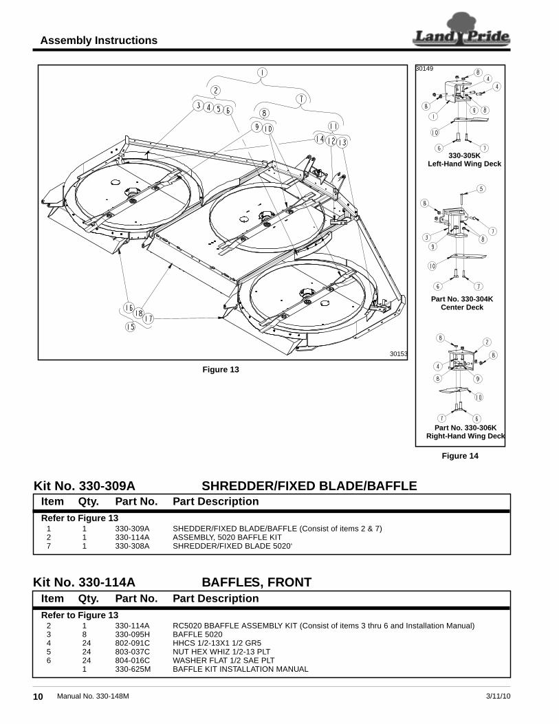
Refer to Figure 131 1 330-309A SHEDDER/FIXED BLADE/BAFFLE (Consist of items 2 & 7)2 1 330-114A ASSEMBLY, 5020 BAFFLE KIT7 1 330-308A SHREDDER/FIXED BLADE 5020‘
Kit No. 330-309A SHREDDER/FIXED BLADE/BAFFLEItem Qty. Part No. Part Description
Kit No. 330-114A BAFFLES, FRONT
Refer to Figure 132 1 330-114A RC5020 BBAFFLE ASSEMBLY KIT (Consist of items 3 thru 6 and Installation Manual)3 8 330-095H BAFFLE 50204 24 802-091C HHCS 1/2-13X1 1/2 GR55 24 803-037C NUT HEX WHIZ 1/2-13 PLT6 24 804-016C WASHER FLAT 1/2 SAE PLT
1 330-625M BAFFLE KIT INSTALLATION MANUAL
Item Qty. Part No. Part Description
Figure 13
30153
Figure 14
Part No. 330-304KCenter Deck
Part No. 330-306KRight-Hand Wing Deck
330-305KLeft-Hand Wing Deck
30149

113/11/10 Manual No. 330-148M
Assembly Instructions
Item Qty. Part No. Part DescriptionRefer to Figure 13
7 1 330-308A SHREDDER/FIXED BLADE 520 (Consist of items 8 & 11)8 1 330-303L SHREDDER KIT 5020 (Consist of items 9 & 10)9 1 330-228S 84" CW BLADE CARRIER ASSEMBLY
10 2 330-302S 84" CCW BLADE CARRIER ASSEMBLY11 1 330-307L FIXED BLADE ASSEMBLY (Consist of items 12, 13 & 14)12 1 330-304K CENTER DECK FIXED BLADE ASSEMBLY13 1 330-305K LEFT-HAND WING DECK FIXED BLADE ASSEMBLY14 1 330-306K RIGHT-HAND WING DECK FIXED BLADE ASSEMBLY
Refer to Figure 5 on page 5:(#1) Components for 330-228S CW Blade Assembly (Quantities shown are for one Assembly)
3 4 312-075D BLADE SPACER 16 GA3 4 312-082D BLADE SPACER 18 GA3 4 312-089D BLADE SPACER 20 GA.3 4 312-808D BLADE SPACER 24GA4 4 318-309D BLADE BUSHING5 1 330-227H BLADE BAR 43"6 2 802-680C HHCS 1-8 X 4 1/2 PLT GR87 2 803-168C NUT HEX TOP LOCK 1-8 PLT9 2 820-377C CUTTER BLADE 1/2 x 4 x 23.5 FLAT
10 2 820-170C CUTTER BLADE 1/2 x 4 x 23 CW
(#2) Components for 330-302S CCW Blade Assembly (Quantities shown are for one Assembly)3 4 312-075D BLADE SPACER 16 GA3 4 312-082D BLADE SPACER 18 GA3 4 312-089D BLADE SPACER 20 GA.3 4 312-808D BLADE SPACER 24GA4 4 318-309D BLADE BUSHING5 1 330-227H BLADE BAR 43"6 2 802-680C HHCS 1-8 X 4 1/2 PLT GR87 2 803-168C NUT HEX TOP LOCK 1-8 PLT8 2 820-169C CUTTER BLADE 1/2 x 4 x 23 CCW9 2 820-377C CUTTER BLADE 1/2 x 4 x 23.5 FLAT
Refer to Figure 14 on page 10:Components for 330-307L Fixed Blade Assembly (Quantities shown are for all 3 Blade Assemblies)
1 1 330-299H BRACKET, FIXED BLADE LH2 1 330-300H BRACKET, FIXED BLADE RH3 1 330-301H BRACKET, FIXED BLADE 20’ CENTER DECK4 8 802-034C HHCS 1/2-13X1 1/4 GR55 1 802-039C HHCS 1/2-13X3 GR56 3 802-064C HHCS 3/4-10X2 GR57 5 802-082C HHCS 1/2-13X1 3/4 GR58 14 803-037C NUT HEX WHIZ 1/2-13 PLT9 3 803-299C NUT HEX FLG TOP LK 3/4-10 PLT
10 3 820-373C CUTTER BLADE 1/2X4X10.25CW/CCW
Kit No. 330-308A SHREDDER/FIXED BLADE
A maximum of four spacersare used per assembly.
A maximum of four spacersare used per assembly.
Refer to Figure 1315 1 330-585A BAFFLES, REAR (Consist of items 16, 17 & 18)16 1 330-620K BAFFLE ASSEMBLY, RH REAR17 1 330-621K BAFFLE ASSEMBLY, LH REAR18 1 330-622K BAFFLE ASSEMBLY, CENTER REAR
Refer to Figure 10, Figure 11 & Figure 12 on page 8:Components for 330-585A Rear Baffles (Quantities shown are for all 3 Rear Baffles)19 1 330-617H REAR BAFFLE RH20 1 330-618H REAR BAFFLE LH21 1 330-159D DEFLECTOR CENTER22 8 802-585C RHSNB 1/2-13X3 1/2 GR5 PLT23 14 802-106C RHSNB 1/2-13X1 1/2 GR524 22 803-037C NUT HEX WHIZ 1/2-13 PLT
Kit No. 330-585A BAFFLES, REARItem Qty. Part No. Part Description

Corporate Office: P.O. Box 5060Salina, Kansas 67402-5060 USA
www.landpride.com