BACnet Option Module Instruction Manual - TR200 · 130R0451 MG12L122 Rev. 2009-06-18 *MG12L122*...
56
BACnet ® Option Module Instruction Manual November 2009 TR200 BAS-SVX24B-EN
Transcript of BACnet Option Module Instruction Manual - TR200 · 130R0451 MG12L122 Rev. 2009-06-18 *MG12L122*...
Rev. 2009-06-18130R0451 MG12L122
*MG12L122*
BACnet® Option Module Instruction Manual
November 2009
TR200 BAS-SVX24B-EN
Trane has a policy of continous product and product data improvement and reserves the right tochange design and specifications without notice.
www.trane.com
For more information, contact your local Traneoffice or e-mail us at [email protected]
Literature Order Number BAS-SVX24A-EN
Date June 2009
Supersedes
Table of Contents
Safety 1-1
Copyright, limitation of liability and revision rights 1-1
High Voltage Warning 1-3
Before Commencing Repair Work 1-8
Special Conditions 1-8
Introduction 2-1
Introduction 2-1
How to Install 3-1
The BACnet Option 3-1
System Specifications 3-5
How to Configure the System 4-1
Configuring BACnet 4-1
BIBBs 4-2
Example of a simple set-up of BACnet 4-3
How to Control the Adjustable Frequency Drive 5-1
Network Adjustable Frequency Drive Control Inputs and Out-puts 5-2
Adjustable Frequency Drive Feedback to Network 5-15
Parameters 6-1
Parameter Overview 6-1
Parameter Description 6-2
Troubleshooting 7-1
Alarm, Warning and Extended Status Word 7-1
Alarm Words 7-2
Warning Words 7-3
TR200 BACnet -1

LED Status 7-4
-2 TR200 BACnet

SafetyCopyright, limitation of liability and revision rights This publication contains information proprietary to Trane. By accepting and using this manual, the user agrees
that the information contained herein will be used solely for operating equipment from Trane or equipment
from other vendors provided that such equipment is intended for communication with Trane equipment over
a serial communication link. This publication is protected under the copyright laws of most countries.
Trane does not warrant that a software program produced according to the guidelines provided in this manual
will function properly in every physical, hardware or software environment.
Although Trane has tested and reviewed the documentation within this manual, Trane makes no warranty or
representation, neither expressed nor implied, with respect to this documentation, including its quality, per-
formance, or fitness for a particular purpose.
In no event shall Trane be liable for direct, indirect, special, incidental, or consequential damages arising out of
the use, or the inability to use information contained in this manual, even if advised of the possibility of such
damages. In particular, Trane is not responsible for any costs, including but not limited to those incurred as a
result of lost profits or revenue, loss or damage of equipment, loss of computer programs, loss of data, the costs
to substitute these, or any claims by third parties.
Trane reserves the right to revise this publication at any time and to make changes to its contents without prior
notice or any obligation to notify former or present users of such revisions or changes.
TR200 BACnet 1-1
Warnings, Cautions and NoticesNote that warnings, cautions and notices appear at appropriate intervals throughout this manual. Warnings are
provided to alert installing contractors to potential hazards that could result in personal injury or death. Cautions
are designed to alert personnel to hazardous situations that could result in personal injury, while notices indicate
a situation that could result in equipment or property damage-only accidents.
Your personal safety and the proper operation of this machine depend upon the strict observance of these
precautions.
Warnings, Cautions and Notices appear at appropriate sections throughout this literature. Read these carefully.
WARNINGIndicates a potentially hazardous situation which, if not avoided, could result in death or serious injury.
CAUTIONIndicates a potentially hazardous situation which, if not avoided, could result in minor or moderate injury. It could alsobe used to alert against unsafe practices.
NOTEIndicates a situation that could result in equipment or property damage-only accidents.
Note
Indicates something important to be noted by the reader.
✮ Indicates default setting
Safety
1-2 TR200 BACnet
High Voltage Warning
WARNINGThe voltage of the adjustable frequency drive is dangerous whenever it is connected to line power. Incorrect installationof the motor or adjustable frequency drive could result indeath, serious injury or damage to the equipment. Conse-quently, it is essential to comply with the instructions in this manual as well as local and national rules and safetyregulations.
Safety Note
WARNINGThe voltage of the adjustable frequency drive is dangerous whenever connected to line power. Incorrect installation ofthe motor, adjustable frequency drive or serial communication bus could result in death, serious personal injury ordamage to the equipment. Consequently, the instructions in this manual, as well as national and local rules and safetyregulations, must be complied with.
WARNINGFailure to follow instructions below could result in death or serious injury.
Safety Regulations1. The adjustable frequency drive must be disconnected from line power if repair work is to be carried out.
Make sure that the line power supply has been disconnected and that the necessary time has passed before
removing motor and line power plugs.
2. The [STOP/RESET] key on the keypad of the adjustable frequency drive does not disconnect the equipment
from line power and is thus not to be used as a safety switch.
3. Correct protective grounding of the equipment must be established, the user must be protected against
supply voltage, and the motor must be protected against overload in accordance with applicable national
and local regulations.
4. The ground leakage currents are higher than 3.5 mA.
5. Protection against motor overload is set by par.1-90 Motor Thermal Protection. If this function is desired,
set par.1-90 Motor Thermal Protection to data value [ETR trip] (default value) or data value [ETR warning].
Note: The function is initialized at 1.16 x rated motor current and rated motor frequency. For the North
American market: The ETR functions provide class 20 motor overload protection in accordance with NEC.
6. Do not remove the plugs for the motor and line power supply while the adjustable frequency drive is con-
nected to line power. Make sure that the line power supply has been disconnected and that the necessary
time has passed before removing motor and line power plugs.
7. Please note that the adjustable frequency drive has more voltage inputs than L1, L2 and L3, when load
sharing (linking of DC intermediate circuit) and external 24 Vdc have been installed. Make sure that all
voltage inputs have been disconnected and that the necessary time has passed before commencing repair
work.
Safety
TR200 BACnet 1-3
Installation at high altitudes
WARNINGInstallation at high altitude:380–500 V, enclosure A, B and C: At altitudes above 6,561 ft [2 km], please contact Trane regarding PELV/Class II.380–500 V, enclosure D, E and F: At altitudes above 9,842 ft [3 km], please contact Trane regarding PELV/Class II.If the drive is to be installed over 6,561 ft [2 km] altitude, then the PELV specifications are not fulfilled anymore, i.e.,the distances between components and critical parts become too small. To maintain the clearance for functional insu-lation anyway, the risk for overvoltage must be reduced by means of external protective devices or some kind of galvanicisolation. De-rating should also be taken into consideration, since cooling the drive is more difficult at high altitude.Please contact Trane in such cases.Failure to follow recommendations could result in death or serious injury.
WARNINGWarning against Unintended Start
1. The motor can be brought to a stop by means of digital commands, bus commands, references or a local stop,while the adjustable frequency drive is connected to line power. If personal safety considerations make it necessaryto ensure that no unintended start occurs, these stop functions are not sufficient.
2. While parameters are being changed, the motor may start. Consequently, the stop key [STOP/RESET] must alwaysbe activated, following which data can be modified.
3. A motor that has been stopped may start if faults occur in the electronics of the adjustable frequency drive, or if atemporary overload or a fault in the supply line power or the motor connection ceases.
Consequently, disconnect all electric power, including remote disconnects before servicing. Follow proper lockout/tagout procedures to ensure the power cannot be inadvertently energized. Failure to follow recommendations couldresult in death or serious injury.
WARNINGTouching the electrical parts could result in death or serious injury - even after the equipment has been disconnectedfrom line power.
Also make sure that other voltage inputs have been disconnected, such as external 24 VDC, load sharing (linkage
of DC intermediate circuit), as well as the motor connection for kinetic backup. Refer to the Instruction Manual
for further safety guidelines.
Failure to follow recommendations could result in death or serious injury.
WARNINGThe adjustable frequency drive DC link capacitors remain charged after power has been disconnected. To avoid anelectrical shock hazard, disconnect the adjustable frequency drive from line power before carrying out maintenance.Wait at least as follows before doing service on the adjustable frequency drive:Failure to follow recommendations could result in death or serious injury.
Safety
1-4 TR200 BACnet

Voltage (V) Min. Waiting Time (Minutes)4 15 20 30 40
200 - 240 1.5–5 hp
[1.1–3.7 kW]
7.5–60 hp
[5.5 –45 kW]
380 - 480 1.5–10 hp
[1.1–7.5 kW]
15–125 hp
[11–90 kW]
150–350 hp
[110–250 kW]
450–1350 hp
[315–1000 kW]
525-600 1.5–10 hp
[1.1–7.5 kW]
15–125 hp
[11–90 kW]
525-690 15–125 hp
[11–90 kW]
60–550 hp
[45–400 kW]
600–1875 hp
[450–1400 kW]
Be aware that there may be high voltage on the DC link even when the LEDs are turned off.
Safety
TR200 BACnet 1-5
Safety Precautions
WARNINGThe voltage of the adjustable frequency drive is dangerous whenever connected to line power. Incorrect installation ofthe motor, adjustable frequency drive or serial communication bus could cause death, serious personal injury or damageto the equipment. Consequently, the instructions in this manual, as well as national and local rules and safety regula-tions, must be complied with.
WARNINGSafety Regulations
1. The line power supply to the adjustable frequency drive must be disconnected whenever repair work is to becarried out. Make sure that the line power supply has been disconnected and that the necessary time has elapsedbefore removing motor and line power supply plugs.
2. The [OFF] button on the control panel of the adjustable frequency driver does not disconnect the line power supplyand consequently it must not be used as a safety switch.
3. The equipment must be properly grounded, the user must be protected against supply voltage and the motor mustbe protected against overload in accordance with applicable national and local regulations.
4. The ground leakage current exceeds 3.5 mA.
5. Protection against motor overload is not included in the factory setting. If this function is desired, set par.1-90 Motor Thermal Protection to data value ETR trip 1 [4] or data value ETR warning 1 [3].
6. Do not remove the plugs for the motor and line power supply while the adjustable frequency drive is connectedto line power. Make sure that the line power supply has been disconnected and that the necessary time has elapsedbefore removing motor and line power plugs.
7. Please note that the adjustable frequency drive has more voltage sources than L1, L2 and L3, when load sharing(linking of DC intermediate circuit) or external 24 V DC are installed. Make sure that all voltage sources have beendisconnected and that the necessary time has elapsed before commencing repair work.
Failure to follow recommendations could result in death or serious injury.
WARNINGWarning against unintended start
1. The motor can be brought to a stop by means of digital commands, bus commands, references or a local stop,while the adjustable frequency drive is connected to line power. If personal safety considerations (e.g., risk ofpersonal injury caused by contact with moving machine parts following an unintentional start) make it necessaryto ensure that no unintended start occurs, these stop functions are not sufficient. In such cases, the line powersupply must be disconnected or the Safe Stop function must be activated.
2. The motor may start while setting the parameters. If this means that personal safety may be compromised (e.g.,personal injury caused by contact with moving machine parts), motor starting must be prevented, for instance byuse of the Safe Stop function or secure disconnection of the motor connection.
3. A motor that has been stopped with the line power supply connected, may start if faults occur in the electronicsof the adjustable frequency drive, through temporary overload or if a fault in the power supply grid or motor con-nection is remedied. If unintended start must be prevented for personal safety reasons (e.g., risk of injury causedby contact with moving machine parts), the normal stop functions of the adjustable frequency drive are not suffi-cient. In such cases, the line power supply must be disconnected or the Safe Stop function must be activated.
Consequently, disconnect all electric power, including remote disconnects before servicing. Follow proper lockout/tagout procedures to ensure the power cannot be inadvertently energized. Failure to follow recommendations couldresult in death or serious injury.
Safety
1-6 TR200 BACnet
Disconnect all electric power, including remote disconnects before servicing. Follow proper lockout/tagout pro-
cedures to ensure the power cannot be inadvertently energized. Failure to follow recommendations could result
in death or serious injury.
1. Control signals from, or internally within, the adjustable frequency drive may in rare cases be activated in
error, be delayed or fail to occur entirely. When used in situations where safety is critical, e.g., when con-
trolling the electromagnetic brake function of a hoist application, these control signals must not be relied
on exclusively.
Note
When using the Safe Stop function, always follow the instructions in the Safe Stop section of the Design Guide.
WARNINGDisconnect all electric power, including remote disconnects. Follow proper lockout/tagout procedures to ensure thepower cannot be inadvertently energized. Use an appropriate voltmeter to verify that the unit is discharged. Failure todisconnect power and ensure unit is discharged before servicing could result in death or serious injury.Also make sure that other voltage inputs have been disconnected, such as external 24 V DC, load sharing (linkage ofDC intermediate circuit), as well as the motor connection for kinetic backup.Systems where adjustable frequency drives are installed must, if necessary, be equipped with additional monitoringand protective devices according to the valid safety regulations, e.g., law on mechanical tools, regulations for theprevention of accidents, etc. Modifications on the adjustable frequency drives by means of the operating software areallowed.Failure to follow recommendations could result in death or serious injury.
Hoisting applications:
The adjustable frequency drive functions for controlling mechanical brakes cannot be considered as a primary
safety circuit. There must always be a redundancy for controlling external brakes.
Protection ModeOnce a hardware limit on motor current or DC link voltage is exceeded, the drive will enter “Protection mode”.
“Protection mode” means a change of the PWM modulation strategy and a low switching frequency to minimize
losses. This continues 10 sec after the last fault and increases the reliability and the robustness of the drive while
re-establishing full control of the motor.
In hoist applications, “Protection mode” is not usable because the drive will usually not be able to leave this
mode again, and therefore it will extend the time before activating the brake – which is not recommended.
"Protection mode” can be disabled by setting par.14-26 Trip Delay at Inverter Fault to zero, which means that
the drive will trip immediately if one of the hardware limits is exceeded.
Note
It is recommended to disable protection mode in hoisting applications (par.14-26 Trip Delay at Inverter Fault =
0).
Safety
TR200 BACnet 1-7
Before Commencing Repair Work
WARNINGHazardous Voltage!
1. Disconnect the adjustable frequency drive from line power.
2. Disconnect DC bus terminals 88 and 89
3. Wait at least the time mentioned above in the section General Warning.
4. Remove motor cable
Failure to follow recommendations could result in death or serious injury.
Special ConditionsElectrical ratings:The rating indicated on the nameplate of the adjustable frequency drive is based on a typical 3-phase line power
supply within the specified voltage, current and temperature ranges, which are expected to be used in most
applications.
The adjustable frequency drives also support other special applications, which affect the electrical ratings of the
adjustable frequency drive.
Special conditions that affect the electrical ratings might be:
• Single phase applications.
• High temperature applications that require derating of the electrical ratings.
• Marine applications with more severe environmental conditions.
Other applications might also affect the electrical ratings.
Consult the relevant sections in this manual and in the for information about the electrical ratings.
Installation requirements:The overall electrical safety of the adjustable frequency drive requires special installation considerations re-
garding:
• Fuses and circuit breakers for overcurrent and short-circuit protection
• Selection of power cables (line power, motor, brake, load sharing and relay)
• Grid configuration (grounded delta transformer leg, IT,TN, etc.)
• Safety of low-voltage ports (PELV conditions).
Consult the relevant clauses in these instructions and in the for information about the installation requirements.
Safety
1-8 TR200 BACnet
IntroductionIntroduction
About this ManualFirst time users can obtain the most essential information for quick installation and set-up in these chapters:
Introduction
How to Install
How to Configure the System
Application Example
For more detailed information including the full range of set-up options and diagnosis tools, refer to the chapters:
How to Control the TR200
How to Access TR200 Parameters
Parameters
Troubleshooting
Technical OverviewBACnet (Building Automation and Control Network) is an open data communications protocol, American Na-
tional Standard (ANSI/ASHRAE 135-1995). BACnet provides a means by which computer-based control equip-
ment from different manufacturers can work together. BACnet is designed to handle many types of building
controls, including HVAC, lighting, security, fire, access control, maintenance and waste management. BACnet
permits flexibility for expansion and different equipment combinations.
Conformance Classes, Function Groups and the PICS: Evaluating the capabilities of a BACnet device is poten-
tially a formidable task, given the great choice of objects, properties and services, which can be implemented,
as well as the fact that it is not necessary for every BACnet device to have a full BACnet implementation in order
to carry out its task. ASHRAE's BACnet Committee recognized this problem and responded with aids to evalu-
ation in the form of "Conformance Classes", "Function Groups" and the "Protocol Implementation Conformance
Statement" (PICS).
The BACnet protocol defines six levels of conformance classes, each of which specifies the minimum subset of
services implemented on the device. The lowest level, Conformance Class 1, requires only that the BACnet
device contain a device object and that it be able to execute (respond to) a ReadProperty service request. Each
successive conformance class level adds service requests that must be executable by the device, as well as the
service requests it must be able to initiate. Conformance Class 6 requires 21 types of service requests (of the 32
overall) to be implemented, of which 20 must be initiable and 17 executable. Conformance class thus provides
a measure of the device's ability to communicate.
Function groups specify a combination of objects and services necessary to carry out certain building automa-
tion functions. They are specified independently of conformance class, though the implementation of some of
the function groups automatically confers some conformance class higher than 1.
TR200 BACnet 2-1
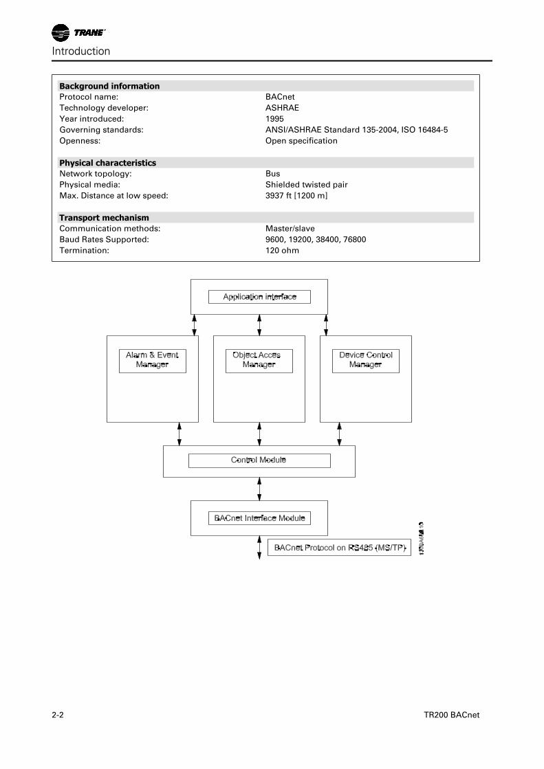
Background informationProtocol name: BACnet
Technology developer: ASHRAE
Year introduced: 1995
Governing standards: ANSI/ASHRAE Standard 135-2004, ISO 16484-5
Openness: Open specification
Physical characteristicsNetwork topology: Bus
Physical media: Shielded twisted pair
Max. Distance at low speed: 3937 ft [1200 m]
Transport mechanismCommunication methods: Master/slave
Baud Rates Supported: 9600, 19200, 38400, 76800
Termination: 120 ohm
Introduction
2-2 TR200 BACnet
AssumptionsThis manual assumes you are using a Trane BACnet Option Card in conjunction with a Trane TR200 series
adjustable frequency drive. It is also assumed that your master is a BMS or PC equipped with a serial commu-
nication card supporting all the BACnet communication services required by your application, and that all
requirements stipulated in the BACnet standard, as well as those pertaining to the Variable Frequency Drive are
strictly observed as well as all limitations therein fully respected.
Background KnowledgeThe Trane BACnet Option Card is designed to communicate with any master complying with the BACnet stand-
ard. Familiarity with the PC or PLC used as a master in the system is assumed. Issues regarding hardware or
software produced by other manufacturers are beyond the scope of this manual and are not the responsibility
of Trane.
If you have questions regarding set-up of master-to-master communication or communication to a non-Trane
slave, consult the appropriate manuals.
Available Literature for TR200
- The Instruction Manual provides the necessary information for getting the drive up and running.
- Instruction Manual TR200 High Power
- The Design Guide contains all the technical information about the drive and customer design and applica-
tions.
- The Programming Guide provides information on how to program and includes complete parameter de-
scriptions.
x = Revision number
yy = Language code
Trane technical literature is available in print from your local Trane Sales Office or online at: www.trane.com/vfd
Introduction
TR200 BACnet 2-3
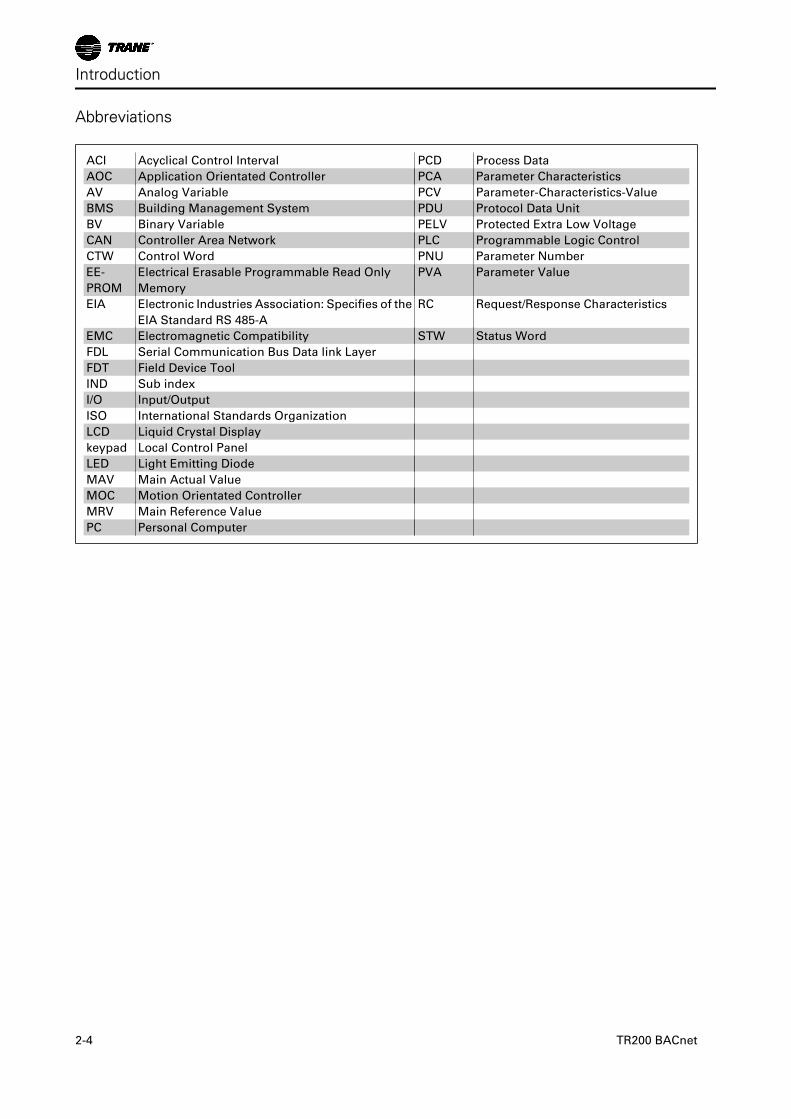
Abbreviations
ACI Acyclical Control Interval PCD Process Data
AOC Application Orientated Controller PCA Parameter Characteristics
AV Analog Variable PCV Parameter-Characteristics-Value
BMS Building Management System PDU Protocol Data Unit
BV Binary Variable PELV Protected Extra Low Voltage
CAN Controller Area Network PLC Programmable Logic Control
CTW Control Word PNU Parameter Number
EE-
PROM
Electrical Erasable Programmable Read Only
Memory
PVA Parameter Value
EIA Electronic Industries Association: Specifies of the
EIA Standard RS 485-A
RC Request/Response Characteristics
EMC Electromagnetic Compatibility STW Status Word
FDL Serial Communication Bus Data link Layer
FDT Field Device Tool
IND Sub index
I/O Input/Output
ISO International Standards Organization
LCD Liquid Crystal Display
keypad Local Control Panel
LED Light Emitting Diode
MAV Main Actual Value
MOC Motion Orientated Controller
MRV Main Reference Value
PC Personal Computer
Introduction
2-4 TR200 BACnet
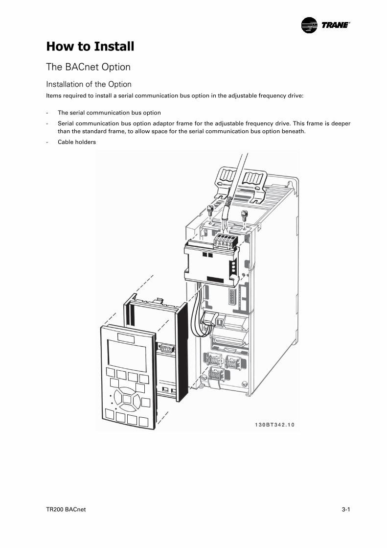
How to InstallThe BACnet Option
Installation of the OptionItems required to install a serial communication bus option in the adjustable frequency drive:
- The serial communication bus option
- Serial communication bus option adaptor frame for the adjustable frequency drive. This frame is deeper
than the standard frame, to allow space for the serial communication bus option beneath.
- Cable holders
TR200 BACnet 3-1
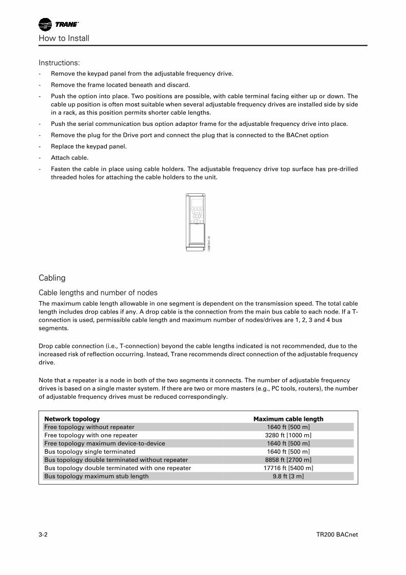
Instructions:- Remove the keypad panel from the adjustable frequency drive.
- Remove the frame located beneath and discard.
- Push the option into place. Two positions are possible, with cable terminal facing either up or down. The
cable up position is often most suitable when several adjustable frequency drives are installed side by side
in a rack, as this position permits shorter cable lengths.
- Push the serial communication bus option adaptor frame for the adjustable frequency drive into place.
- Remove the plug for the Drive port and connect the plug that is connected to the BACnet option
- Replace the keypad panel.
- Attach cable.
- Fasten the cable in place using cable holders. The adjustable frequency drive top surface has pre-drilled
threaded holes for attaching the cable holders to the unit.
130B
T341
.10
Cabling
Cable lengths and number of nodesThe maximum cable length allowable in one segment is dependent on the transmission speed. The total cable
length includes drop cables if any. A drop cable is the connection from the main bus cable to each node. If a T-
connection is used, permissible cable length and maximum number of nodes/drives are 1, 2, 3 and 4 bus
segments.
Drop cable connection (i.e., T-connection) beyond the cable lengths indicated is not recommended, due to the
increased risk of reflection occurring. Instead, Trane recommends direct connection of the adjustable frequency
drive.
Note that a repeater is a node in both of the two segments it connects. The number of adjustable frequency
drives is based on a single master system. If there are two or more masters (e.g., PC tools, routers), the number
of adjustable frequency drives must be reduced correspondingly.
Network topology Maximum cable lengthFree topology without repeater 1640 ft [500 m]
Free topology with one repeater 3280 ft [1000 m]
Free topology maximum device-to-device 1640 ft [500 m]
Bus topology single terminated 1640 ft [500 m]
Bus topology double terminated without repeater 8858 ft [2700 m]
Bus topology double terminated with one repeater 17716 ft [5400 m]
Bus topology maximum stub length 9.8 ft [3 m]
How to Install
3-2 TR200 BACnet
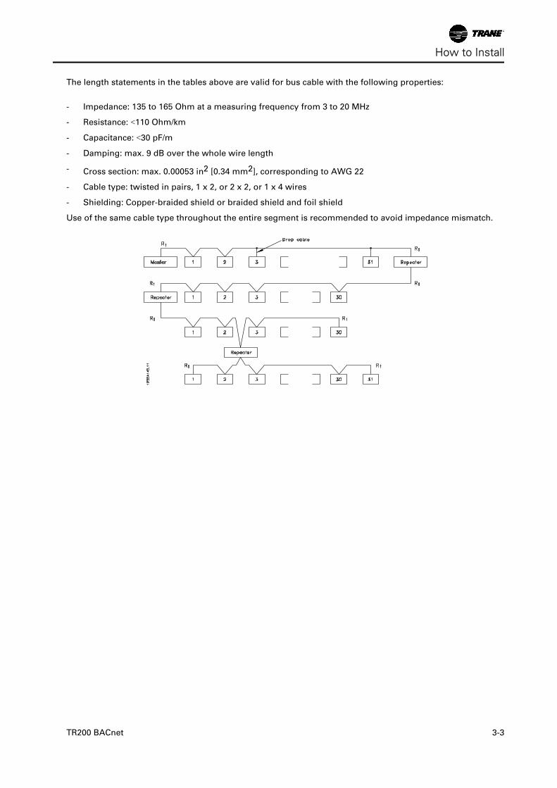
The length statements in the tables above are valid for bus cable with the following properties:
- Impedance: 135 to 165 Ohm at a measuring frequency from 3 to 20 MHz
- Resistance: <110 Ohm/km
- Capacitance: <30 pF/m
- Damping: max. 9 dB over the whole wire length
- Cross section: max. 0.00053 in2 [0.34 mm2], corresponding to AWG 22
- Cable type: twisted in pairs, 1 x 2, or 2 x 2, or 1 x 4 wires
- Shielding: Copper-braided shield or braided shield and foil shield
Use of the same cable type throughout the entire segment is recommended to avoid impedance mismatch.
How to Install
TR200 BACnet 3-3
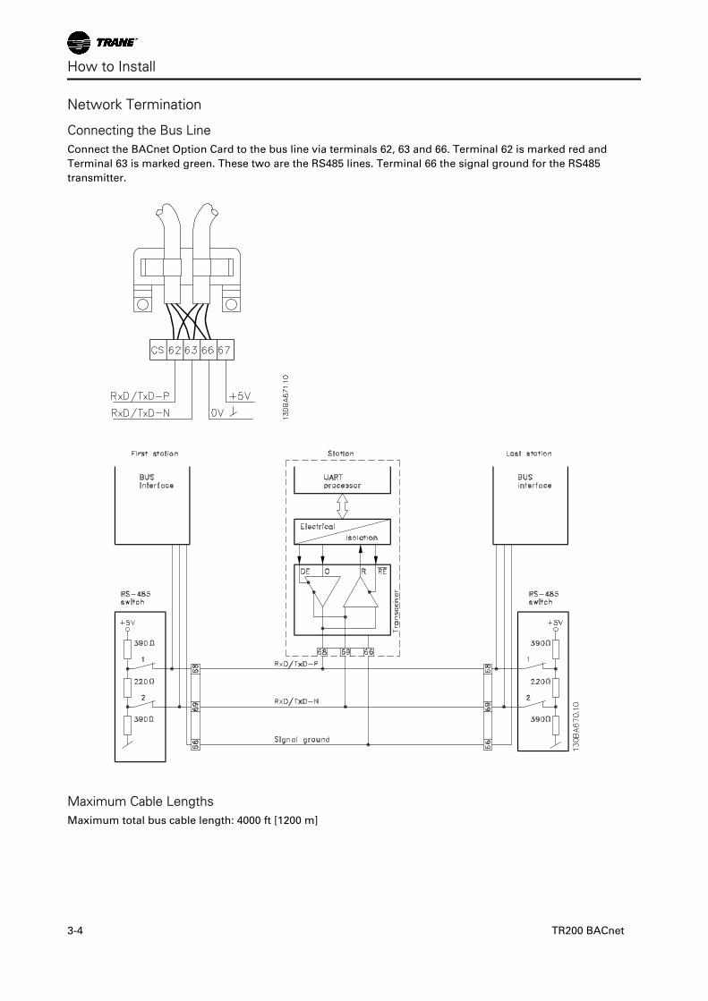
Network Termination
Connecting the Bus LineConnect the BACnet Option Card to the bus line via terminals 62, 63 and 66. Terminal 62 is marked red and
Terminal 63 is marked green. These two are the RS485 lines. Terminal 66 the signal ground for the RS485
transmitter.
Maximum Cable LengthsMaximum total bus cable length: 4000 ft [1200 m]
How to Install
3-4 TR200 BACnet
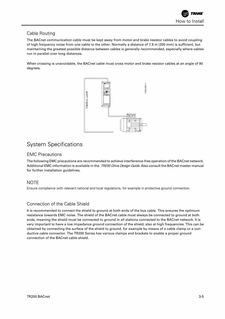
Cable RoutingThe BACnet communication cable must be kept away from motor and brake resistor cables to avoid coupling
of high frequency noise from one cable to the other. Normally a distance of 7.9 in (200 mm) is sufficient, but
maintaining the greatest possible distance between cables is generally recommended, especially where cables
run in parallel over long distances.
When crossing is unavoidable, the BACnet cable must cross motor and brake resistor cables at an angle of 90
degrees.
System Specifications
EMC PrecautionsThe following EMC precautions are recommended to achieve interference-free operation of the BACnet network.
Additional EMC information is available in the TR200 Drive Design Guide. Also consult the BACnet master manual
for further installation guidelines.
NOTEEnsure compliance with relevant national and local regulations, for example in protective ground connection.
Connection of the Cable ShieldIt is recommended to connect the shield to ground at both ends of the bus cable. This ensures the optimum
resistance towards EMC noise. The shield of the BACnet cable must always be connected to ground at both
ends, meaning the shield must be connected to ground in all stations connected to the BACnet network. It is
very important to have a low impedance ground connection of the shield, also at high frequencies. This can be
obtained by connecting the surface of the shield to ground, for example by means of a cable clamp or a con-
ductive cable connector. The TR200 Series has various clamps and brackets to enable a proper ground
connection of the BACnet cable shield.
How to Install
TR200 BACnet 3-5

Ground ConnectionIt is important that all stations connected to the BACnet network are connected to the same ground potential.
The ground connection must have low HF (high frequency) impedance. This can be achieved by connecting a
large surface area of the cabinet to ground, for example by mounting the TR200 series on a conductive rear
plate. Particularly when there are long distances between the stations in a BACnet network, it may be necessary
to use additional potential equalizing cables, connecting the individual stations to the same ground potential.
The use of repeaters with galvanic isolation or fiber optic can improve the EMC performance and reduce ground
loop current.
How to Install
3-6 TR200 BACnet
How to Configure the SystemConfiguring BACnet
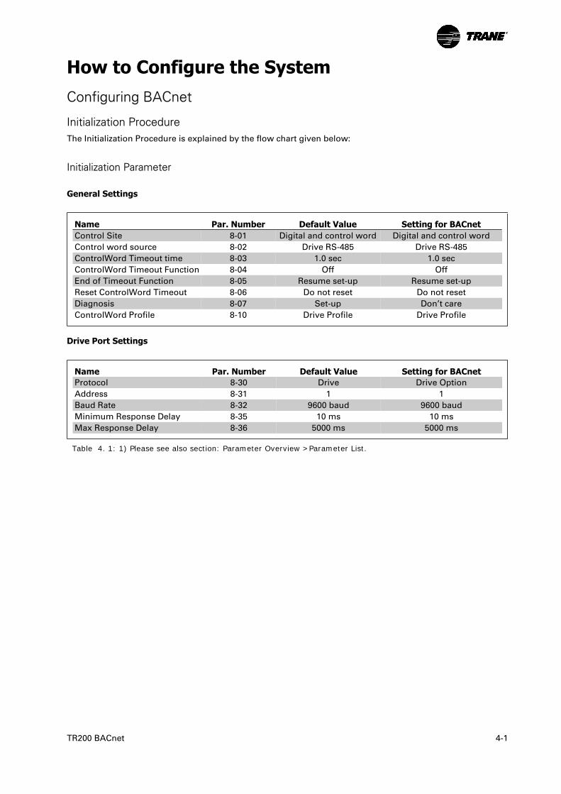
Initialization ProcedureThe Initialization Procedure is explained by the flow chart given below:
Initialization Parameter
General Settings
Name Par. Number Default Value Setting for BACnetControl Site 8-01 Digital and control word Digital and control word
Control word source 8-02 Drive RS-485 Drive RS-485
ControlWord Timeout time 8-03 1.0 sec 1.0 sec
ControlWord Timeout Function 8-04 Off Off
End of Timeout Function 8-05 Resume set-up Resume set-up
Reset ControlWord Timeout 8-06 Do not reset Do not reset
Diagnosis 8-07 Set-up Don’t care
ControlWord Profile 8-10 Drive Profile Drive Profile
Drive Port Settings
Name Par. Number Default Value Setting for BACnetProtocol 8-30 Drive Drive Option
Address 8-31 1 1
Baud Rate 8-32 9600 baud 9600 baud
Minimum Response Delay 8-35 10 ms 10 ms
Max Response Delay 8-36 5000 ms 5000 ms
Table 4. 1: 1) Please see also section: Parameter Overview >Parameter List.
TR200 BACnet 4-1
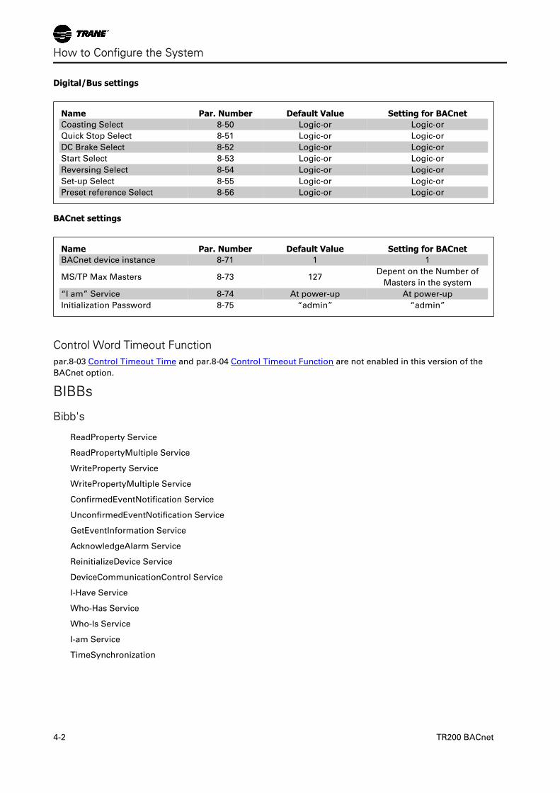
Digital/Bus settings
Name Par. Number Default Value Setting for BACnetCoasting Select 8-50 Logic-or Logic-or
Quick Stop Select 8-51 Logic-or Logic-or
DC Brake Select 8-52 Logic-or Logic-or
Start Select 8-53 Logic-or Logic-or
Reversing Select 8-54 Logic-or Logic-or
Set-up Select 8-55 Logic-or Logic-or
Preset reference Select 8-56 Logic-or Logic-or
BACnet settings
Name Par. Number Default Value Setting for BACnetBACnet device instance 8-71 1 1
MS/TP Max Masters 8-73 127Depent on the Number of
Masters in the system
“I am” Service 8-74 At power-up At power-up
Initialization Password 8-75 “admin” “admin”
Control Word Timeout Functionpar.8-03 Control Timeout Time and par.8-04 Control Timeout Function are not enabled in this version of the
BACnet option.
BIBBs
Bibb's
ReadProperty Service
ReadPropertyMultiple Service
WriteProperty Service
WritePropertyMultiple Service
ConfirmedEventNotification Service
UnconfirmedEventNotification Service
GetEventInformation Service
AcknowledgeAlarm Service
ReinitializeDevice Service
DeviceCommunicationControl Service
I-Have Service
Who-Has Service
Who-Is Service
I-am Service
TimeSynchronization
How to Configure the System
4-2 TR200 BACnet
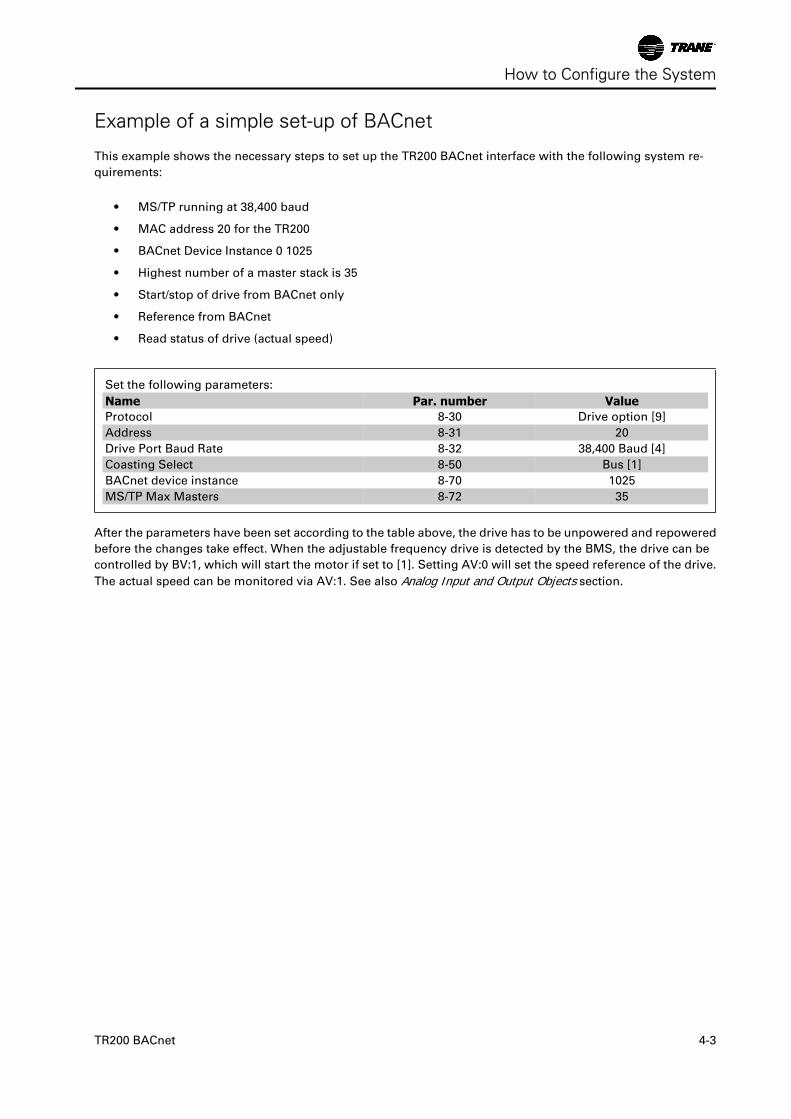
Example of a simple set-up of BACnet
This example shows the necessary steps to set up the TR200 BACnet interface with the following system re-
quirements:
• MS/TP running at 38,400 baud
• MAC address 20 for the TR200
• BACnet Device Instance 0 1025
• Highest number of a master stack is 35
• Start/stop of drive from BACnet only
• Reference from BACnet
• Read status of drive (actual speed)
Set the following parameters:
Name Par. number ValueProtocol 8-30 Drive option [9]
Address 8-31 20
Drive Port Baud Rate 8-32 38,400 Baud [4]
Coasting Select 8-50 Bus [1]
BACnet device instance 8-70 1025
MS/TP Max Masters 8-72 35
After the parameters have been set according to the table above, the drive has to be unpowered and repowered
before the changes take effect. When the adjustable frequency drive is detected by the BMS, the drive can be
controlled by BV:1, which will start the motor if set to [1]. Setting AV:0 will set the speed reference of the drive.
The actual speed can be monitored via AV:1. See also Analog Input and Output Objects section.
How to Configure the System
TR200 BACnet 4-3

How to Configure the System
4-4 TR200 BACnet
How to Control the Adjustable Frequency DriveReference HandlingSelect the adjustable frequency drive configuration mode in par.1-00 Configuration Mode.
[0] Open-loop
[3] Closed-loop
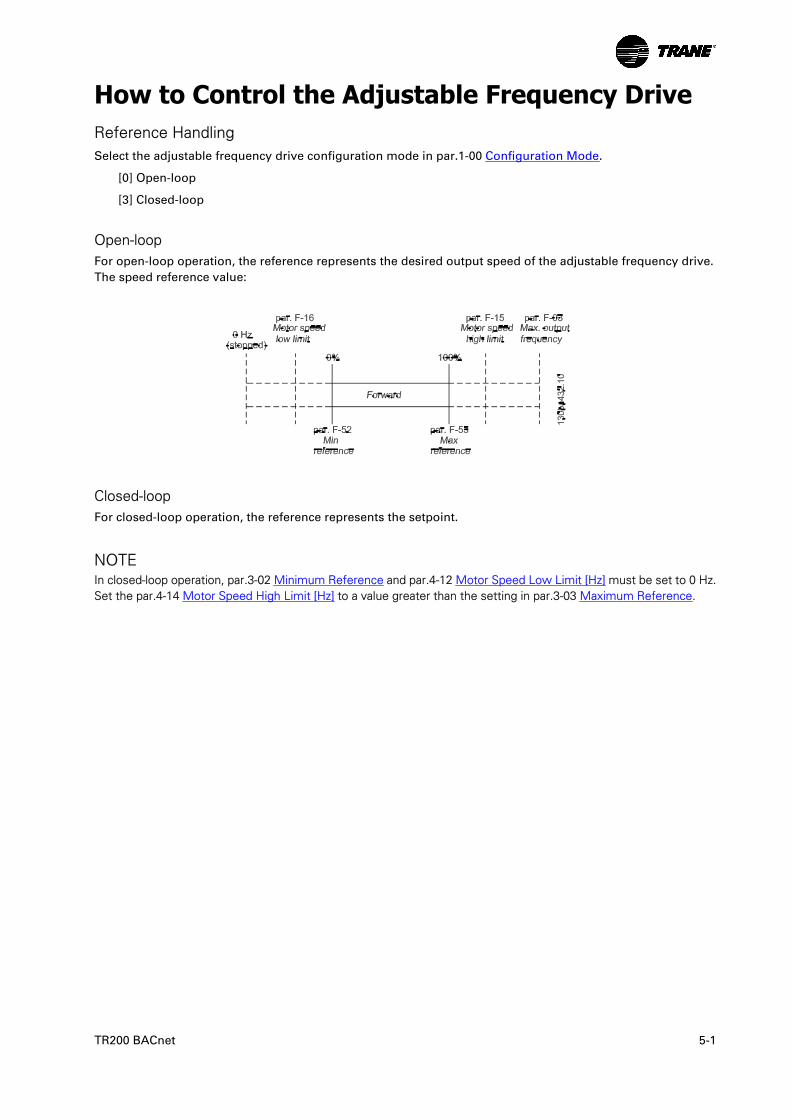
Open-loopFor open-loop operation, the reference represents the desired output speed of the adjustable frequency drive.
The speed reference value:
Closed-loopFor closed-loop operation, the reference represents the setpoint.
NOTEIn closed-loop operation, par.3-02 Minimum Reference and par.4-12 Motor Speed Low Limit [Hz] must be set to 0 Hz.Set the par.4-14 Motor Speed High Limit [Hz] to a value greater than the setting in par.3-03 Maximum Reference.
TR200 BACnet 5-1
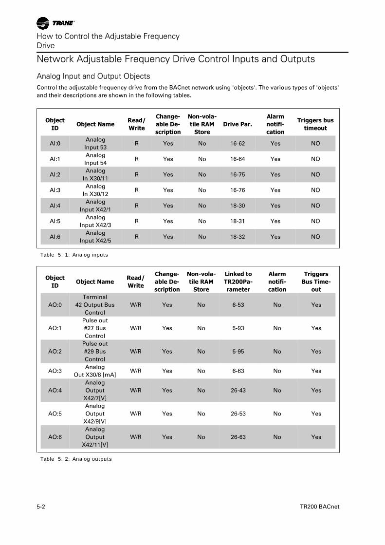
Network Adjustable Frequency Drive Control Inputs and Outputs
Analog Input and Output ObjectsControl the adjustable frequency drive from the BACnet network using 'objects'. The various types of 'objects'
and their descriptions are shown in the following tables.
ObjectID
Object NameRead/Write
Change-able De-scription
Non-vola-tile RAM
StoreDrive Par.
Alarmnotifi-cation
Triggers bustimeout
AI:0Analog
Input 53R Yes No 16-62 Yes NO
AI:1Analog
Input 54R Yes No 16-64 Yes NO
AI:2Analog
In X30/11R Yes No 16-75 Yes NO
AI:3Analog
In X30/12R Yes No 16-76 Yes NO
AI:4Analog
Input X42/1R Yes No 18-30 Yes NO
AI:5Analog
Input X42/3R Yes No 18-31 Yes NO
AI:6Analog
Input X42/5R Yes No 18-32 Yes NO
Table 5. 1: Analog inputs
ObjectID
Object NameRead/Write
Change-able De-scription
Non-vola-tile RAM
Store
Linked toTR200Pa-rameter
Alarmnotifi-cation
TriggersBus Time-
out
AO:0
Terminal
42 Output Bus
Control
W/R Yes No 6-53 No Yes
AO:1
Pulse out
#27 Bus
Control
W/R Yes No 5-93 No Yes
AO:2
Pulse out
#29 Bus
Control
W/R Yes No 5-95 No Yes
AO:3Analog
Out X30/8 [mA]W/R Yes No 6-63 No Yes
AO:4
Analog
Output
X42/7[V]
W/R Yes No 26-43 No Yes
AO:5
Analog
Output
X42/9[V]
W/R Yes No 26-53 No Yes
AO:6
Analog
Output
X42/11[V]
W/R Yes No 26-63 No Yes
Table 5. 2: Analog outputs
How to Control the Adjustable FrequencyDrive
5-2 TR200 BACnet
ObjectID
Object NameRead/Write
Change-able De-scription
Non-vola-tile RAM
Store
TR200Pa-rameter
Alarmnotifi-cation
Triggers BusTimeout
AV:0 Reference W/R Yes No MRV No Yes
AV:1 Speed Act. Value W/R Yes No MAV Yes Yes
AV:2 Bus Feedback1 W/R Yes No 8-94 No Yes
AV:3 Bus Feedback2 W/R Yes No 8-95 No Yes
AV:4 Bus Feedback3 W/R Yes No 8-96 No Yes
AV:5 Motor Voltage Read Yes No 16-12 Yes No
AV:6 Motor Current Read Yes No 16-14 Yes No
AV:7 Motor Torque % Read Yes No 16-22 Yes No
AV:8 DC Link Voltage Read Yes No 16-30 Yes No
AV:9 Motor Thermal Read Yes No 16-18 Yes No
AV:10Heatsink Temper-
atureRead Yes No 16-34 Yes No
AV:11 Inverter Thermal Read Yes No 16-35 Yes No
AV:12 Operating Hours Read No No 15-00 No No
AV:13 Running Hours Read No No 15-01 No No
AV:14 KWh Counter Read No No 15-02 No No
AV:15 Power [KW] Read No No 16-10 No No
AV:16PID Start Speed
[Hz]W/R No TR200 20-83 No No
AV:17PID Proportional
GainW/R No TR200 20-93 No No
AV:18PID Integral Time
(Sec)W/R No TR200 20-94 No No
AV:19PID Differential
Time (Sec)W/R No TR200 20-95 No No
AV:20 PID Dif. Gain Limit W/R No TR200 20-96 No No
AV:21On Reference
BandwithW/R No TR200 20-84 No No
AV:22 Ext. 1 Setpoint W/R No TR200 21-15 No No
AV:23Ext. 1 Reference
[Unit]W/R No TR200 21-17 No No
AV:24Ext. 1 Feedback
[Unit]W/R No TR200 21-18 No No
AV:25Ext. 1 Proportion-
al GainW/R No TR200 21-21 No No
AV:26 Reserved W/R No Na
AV:27Ext. 1 Integral
Time (Sec)W/R No TR200 21-22 No No
AV:28Ext. 1 Differential
Time (Sec)W/R No TR200 21-23 No No
AV:29Ext. 1 Dif. Gain
LimitW/R No TR200 21-24 No No
AV:30 Reserved W/R No Na
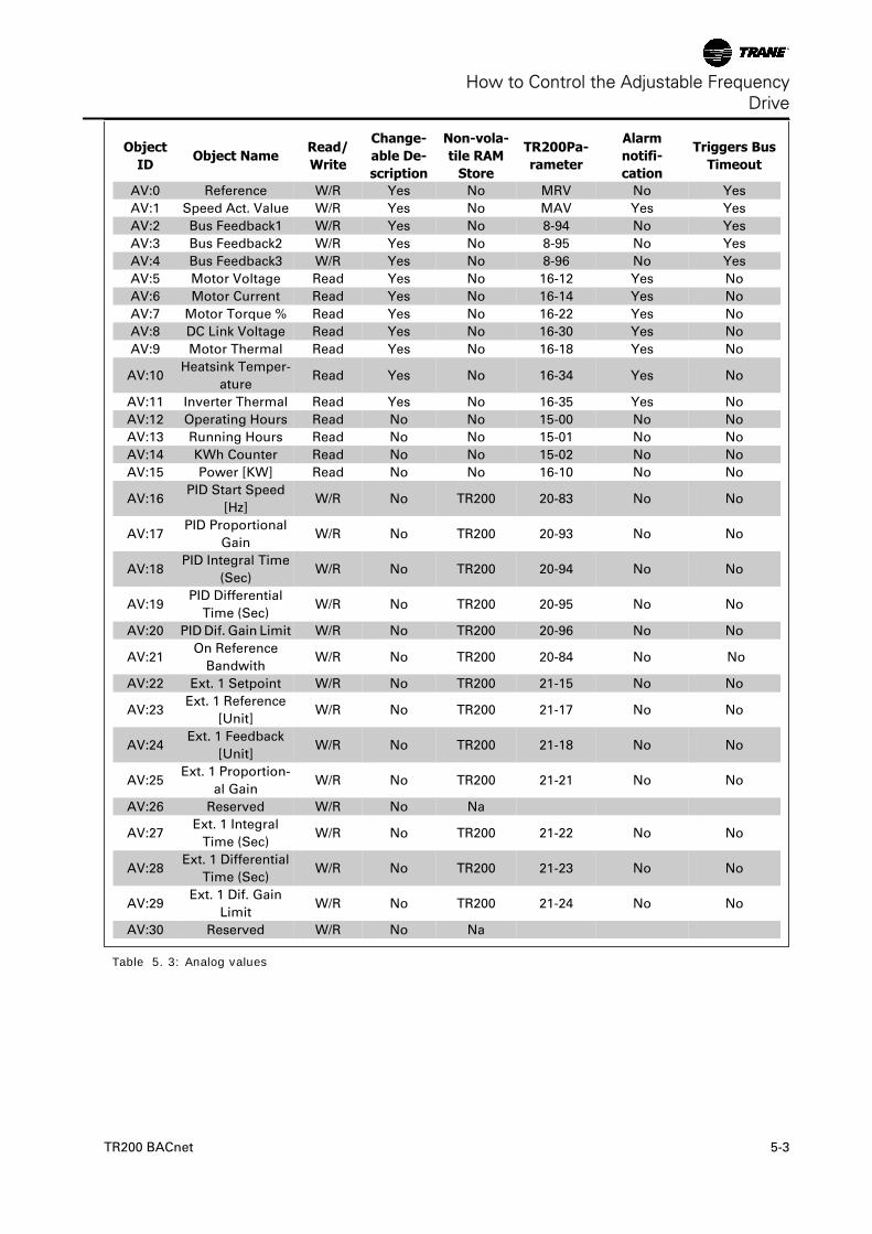
Table 5. 3: Analog values
How to Control the Adjustable FrequencyDrive
TR200 BACnet 5-3
ObjectID
Object NameRead/Write
Change-able De-scription
Non-vola-tile RAM
Store
TR200 Pa-rameter
Alarmnotifi-cation
Triggers BusTimeout
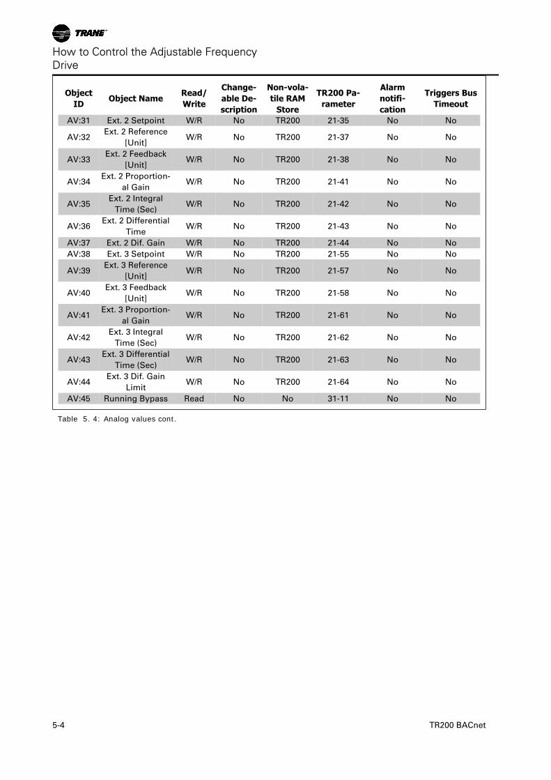
AV:31 Ext. 2 Setpoint W/R No TR200 21-35 No No
AV:32Ext. 2 Reference
[Unit]W/R No TR200 21-37 No No
AV:33Ext. 2 Feedback
[Unit]W/R No TR200 21-38 No No
AV:34Ext. 2 Proportion-
al GainW/R No TR200 21-41 No No
AV:35Ext. 2 Integral
Time (Sec)W/R No TR200 21-42 No No
AV:36Ext. 2 Differential
TimeW/R No TR200 21-43 No No
AV:37 Ext. 2 Dif. Gain W/R No TR200 21-44 No No
AV:38 Ext. 3 Setpoint W/R No TR200 21-55 No No
AV:39Ext. 3 Reference
[Unit]W/R No TR200 21-57 No No
AV:40Ext. 3 Feedback
[Unit]W/R No TR200 21-58 No No
AV:41Ext. 3 Proportion-
al GainW/R No TR200 21-61 No No
AV:42Ext. 3 Integral
Time (Sec)W/R No TR200 21-62 No No
AV:43Ext. 3 Differential
Time (Sec)W/R No TR200 21-63 No No
AV:44Ext. 3 Dif. Gain
LimitW/R No TR200 21-64 No No
AV:45 Running Bypass Read No No 31-11 No No
Table 5. 4: Analog values cont.
How to Control the Adjustable FrequencyDrive
5-4 TR200 BACnet
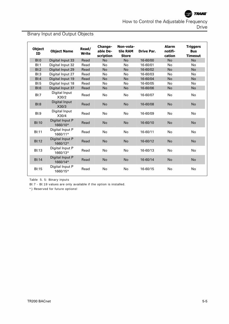
Binary Input and Output Objects
ObjectID
Object NameRead/Write
Change-able De-scription
Non-vola-tile RAM
StoreDrive Par.
Alarmnotifi-cation
TriggersBus
TimeoutBI:0 Digital Input 33 Read No No 16-60/00 No No
BI:1 Digital Input 32 Read No No 16-60/01 No No
BI:2 Digital Input 29 Read No No 16-60/02 No No
BI:3 Digital Input 27 Read No No 16-60/03 No No
BI:4 Digital Input 19 Read No No 16-60/04 No No
BI:5 Digital Input 18 Read No No 16-60/05 No No
BI:6 Digital Input 37 Read No No 16-60/06 No No
BI:7Digital Input
X30/2Read No No 16-60/07 No No
BI:8Digital Input
X30/3Read No No 16-60/08 No No
BI:9Digital Input
X30/4Read No No 16-60/09 No No
BI:10Digital Input P
1660/10*Read No No 16-60/10 No No
BI:11Digital Input P
1660/11*Read No No 16-60/11 No No
BI:12Digital Input P
1660/12*Read No No 16-60/12 No No
BI:13Digital Input P
1660/13*Read No No 16-60/13 No No
BI:14Digital Input P
1660/14*Read No No 16-60/14 No No
BI:15Digital Input P
1660/15*Read No No 16-60/15 No No
Table 5. 5: Binary inputsBl:7 - Bl:19 values are only available if the option is installed.*) Reserved for future options!
How to Control the Adjustable FrequencyDrive
TR200 BACnet 5-5
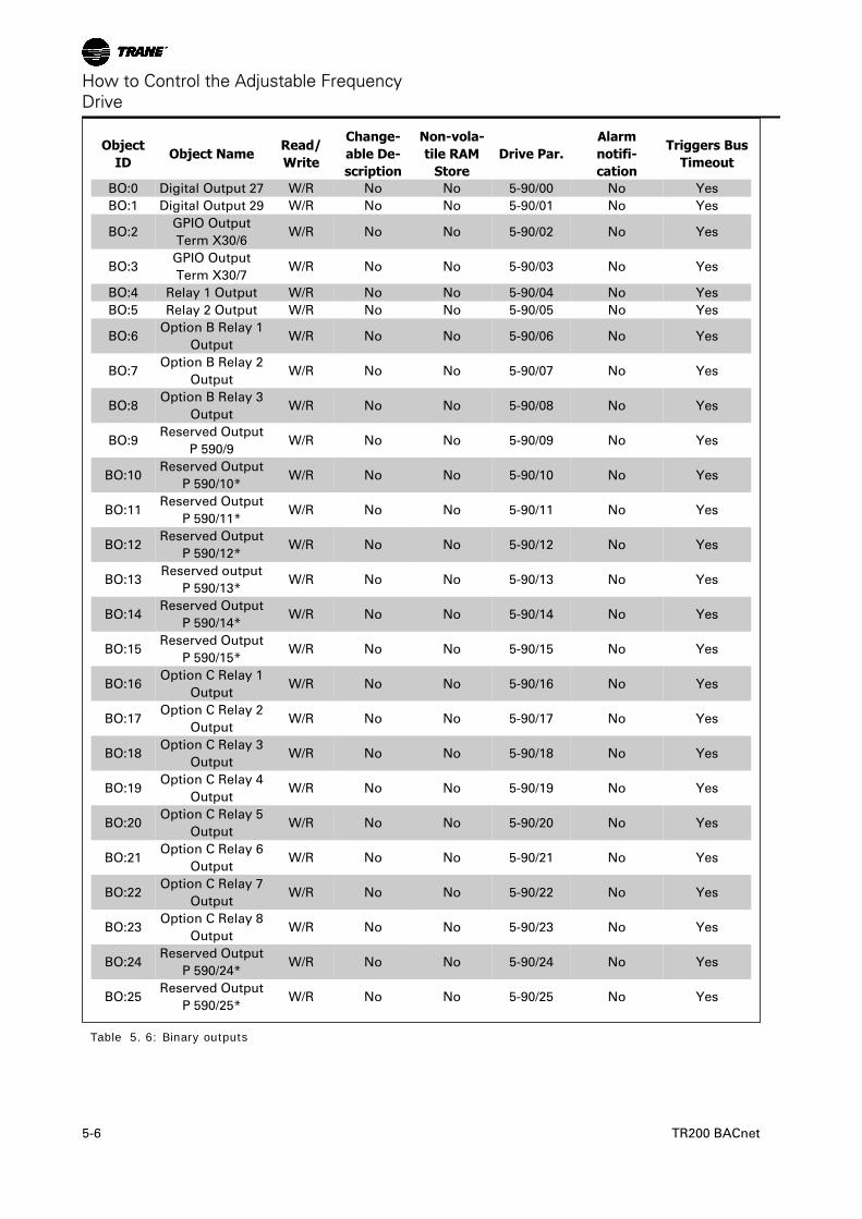
ObjectID
Object NameRead/Write
Change-able De-scription
Non-vola-tile RAM
StoreDrive Par.
Alarmnotifi-cation
Triggers BusTimeout
BO:0 Digital Output 27 W/R No No 5-90/00 No Yes
BO:1 Digital Output 29 W/R No No 5-90/01 No Yes
BO:2GPIO Output
Term X30/6W/R No No 5-90/02 No Yes
BO:3GPIO Output
Term X30/7W/R No No 5-90/03 No Yes
BO:4 Relay 1 Output W/R No No 5-90/04 No Yes
BO:5 Relay 2 Output W/R No No 5-90/05 No Yes
BO:6Option B Relay 1
OutputW/R No No 5-90/06 No Yes
BO:7Option B Relay 2
OutputW/R No No 5-90/07 No Yes
BO:8Option B Relay 3
OutputW/R No No 5-90/08 No Yes
BO:9Reserved Output
P 590/9W/R No No 5-90/09 No Yes
BO:10Reserved Output
P 590/10*W/R No No 5-90/10 No Yes
BO:11Reserved Output
P 590/11*W/R No No 5-90/11 No Yes
BO:12Reserved Output
P 590/12*W/R No No 5-90/12 No Yes
BO:13Reserved output
P 590/13*W/R No No 5-90/13 No Yes
BO:14Reserved Output
P 590/14*W/R No No 5-90/14 No Yes
BO:15Reserved Output
P 590/15*W/R No No 5-90/15 No Yes
BO:16Option C Relay 1
OutputW/R No No 5-90/16 No Yes
BO:17Option C Relay 2
OutputW/R No No 5-90/17 No Yes
BO:18Option C Relay 3
OutputW/R No No 5-90/18 No Yes
BO:19Option C Relay 4
OutputW/R No No 5-90/19 No Yes
BO:20Option C Relay 5
OutputW/R No No 5-90/20 No Yes
BO:21Option C Relay 6
OutputW/R No No 5-90/21 No Yes
BO:22Option C Relay 7
OutputW/R No No 5-90/22 No Yes
BO:23Option C Relay 8
OutputW/R No No 5-90/23 No Yes
BO:24Reserved Output
P 590/24*W/R No No 5-90/24 No Yes
BO:25Reserved Output
P 590/25*W/R No No 5-90/25 No Yes
Table 5. 6: Binary outputs
How to Control the Adjustable FrequencyDrive
5-6 TR200 BACnet
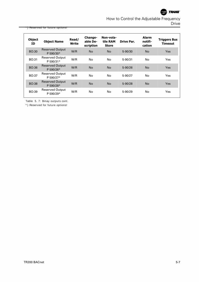
*) Reserved for future options!
ObjectID
Object NameRead/Write
Change-able De-scription
Non-vola-tile RAM
StoreDrive Par.
Alarmnotifi-cation
Triggers BusTimeout
BO:30Reserved Output
P 590/30*W/R No No 5-90/30 No Yes
BO:31Reserved Output
P 590/31*W/R No No 5-90/31 No Yes
BO:36Reserved Output
P 590/26*W/R No No 5-90/26 No Yes
BO:37Reserved Output
P 590/27*W/R No No 5-90/27 No Yes
BO:38Reserved Output
P 590/28*W/R No No 5-90/28 No Yes
BO:39Reserved Output
P 590/29*W/R No No 5-90/29 No Yes
Table 5. 7: Binay outputs cont.*) Reserved for future options!
How to Control the Adjustable FrequencyDrive
TR200 BACnet 5-7
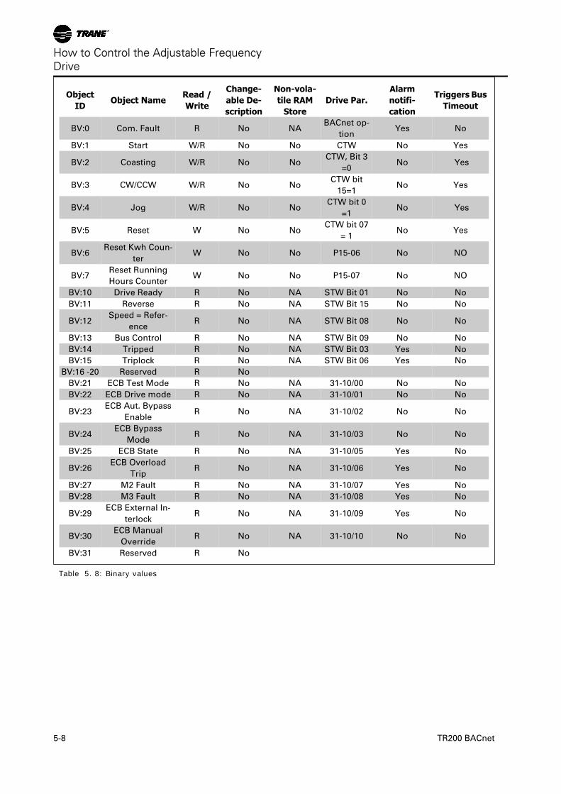
ObjectID
Object NameRead /Write
Change-able De-scription
Non-vola-tile RAM
StoreDrive Par.
Alarmnotifi-cation
Triggers BusTimeout
BV:0 Com. Fault R No NABACnet op-
tionYes No
BV:1 Start W/R No No CTW No Yes
BV:2 Coasting W/R No NoCTW, Bit 3
=0No Yes
BV:3 CW/CCW W/R No NoCTW bit
15=1No Yes
BV:4 Jog W/R No NoCTW bit 0
=1No Yes
BV:5 Reset W No NoCTW bit 07
= 1No Yes
BV:6Reset Kwh Coun-
terW No No P15-06 No NO
BV:7Reset Running
Hours CounterW No No P15-07 No NO
BV:10 Drive Ready R No NA STW Bit 01 No No
BV:11 Reverse R No NA STW Bit 15 No No
BV:12Speed = Refer-
enceR No NA STW Bit 08 No No
BV:13 Bus Control R No NA STW Bit 09 No No
BV:14 Tripped R No NA STW Bit 03 Yes No
BV:15 Triplock R No NA STW Bit 06 Yes No
BV:16 -20 Reserved R No
BV:21 ECB Test Mode R No NA 31-10/00 No No
BV:22 ECB Drive mode R No NA 31-10/01 No No
BV:23ECB Aut. Bypass
EnableR No NA 31-10/02 No No
BV:24ECB Bypass
ModeR No NA 31-10/03 No No
BV:25 ECB State R No NA 31-10/05 Yes No
BV:26ECB Overload
TripR No NA 31-10/06 Yes No
BV:27 M2 Fault R No NA 31-10/07 Yes No
BV:28 M3 Fault R No NA 31-10/08 Yes No
BV:29ECB External In-
terlockR No NA 31-10/09 Yes No
BV:30ECB Manual
OverrideR No NA 31-10/10 No No
BV:31 Reserved R No
Table 5. 8: Binary values
How to Control the Adjustable FrequencyDrive
5-8 TR200 BACnet
ObjectID
Object NameRead /Write
Change-able De-scription
Non-vola-tile RAM
StoreDrive Par.
Alarmnotifi-cation
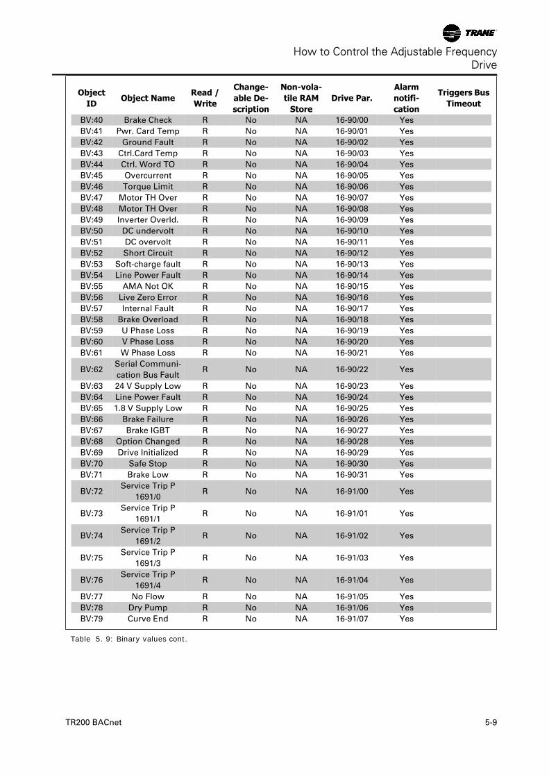
Triggers BusTimeout
BV:40 Brake Check R No NA 16-90/00 Yes
BV:41 Pwr. Card Temp R No NA 16-90/01 Yes
BV:42 Ground Fault R No NA 16-90/02 Yes
BV:43 Ctrl.Card Temp R No NA 16-90/03 Yes
BV:44 Ctrl. Word TO R No NA 16-90/04 Yes
BV:45 Overcurrent R No NA 16-90/05 Yes
BV:46 Torque Limit R No NA 16-90/06 Yes
BV:47 Motor TH Over R No NA 16-90/07 Yes
BV:48 Motor TH Over R No NA 16-90/08 Yes
BV:49 Inverter Overld. R No NA 16-90/09 Yes
BV:50 DC undervolt R No NA 16-90/10 Yes
BV:51 DC overvolt R No NA 16-90/11 Yes
BV:52 Short Circuit R No NA 16-90/12 Yes
BV:53 Soft-charge fault R No NA 16-90/13 Yes
BV:54 Line Power Fault R No NA 16-90/14 Yes
BV:55 AMA Not OK R No NA 16-90/15 Yes
BV:56 Live Zero Error R No NA 16-90/16 Yes
BV:57 Internal Fault R No NA 16-90/17 Yes
BV:58 Brake Overload R No NA 16-90/18 Yes
BV:59 U Phase Loss R No NA 16-90/19 Yes
BV:60 V Phase Loss R No NA 16-90/20 Yes
BV:61 W Phase Loss R No NA 16-90/21 Yes
BV:62Serial Communi-
cation Bus FaultR No NA 16-90/22 Yes
BV:63 24 V Supply Low R No NA 16-90/23 Yes
BV:64 Line Power Fault R No NA 16-90/24 Yes
BV:65 1.8 V Supply Low R No NA 16-90/25 Yes
BV:66 Brake Failure R No NA 16-90/26 Yes
BV:67 Brake IGBT R No NA 16-90/27 Yes
BV:68 Option Changed R No NA 16-90/28 Yes
BV:69 Drive Initialized R No NA 16-90/29 Yes
BV:70 Safe Stop R No NA 16-90/30 Yes
BV:71 Brake Low R No NA 16-90/31 Yes
BV:72Service Trip P
1691/0R No NA 16-91/00 Yes
BV:73Service Trip P
1691/1R No NA 16-91/01 Yes
BV:74Service Trip P
1691/2R No NA 16-91/02 Yes
BV:75Service Trip P
1691/3R No NA 16-91/03 Yes
BV:76Service Trip P
1691/4R No NA 16-91/04 Yes
BV:77 No Flow R No NA 16-91/05 Yes
BV:78 Dry Pump R No NA 16-91/06 Yes
BV:79 Curve End R No NA 16-91/07 Yes
Table 5. 9: Binary values cont.
How to Control the Adjustable FrequencyDrive
TR200 BACnet 5-9
ObjectID
Object NameRead /Write
Change-able De-scription
Non-vola-tile RAM
StoreDrive Par.
Alarmnotifi-cation
Triggers BusTimeout
BV:80 Broken Belt R No NA 16-91/08 Yes
BV:81 Discharge High R No NA 16-91/08 Yes
BV:82 Start Fault R No NA 16-91/10 Yes
BV:83 Speed Limit R No NA 16-91/11 Yes
BV:84State Fault P
1691/12R No NA 16-91/12 Yes
BV:85State Fault P
1691/13R No NA 16-91/13 Yes
BV:86State Fault P
1691/14R No NA 16-91/14 Yes
BV:87State Fault P
1691/15R No NA 16-91/15 Yes
BV:88KTY Temperature
ErrorR No NA 16-91/16 Yes
BV:89 Drive Fan Error R No NA 16-91/17 Yes
BV:90 ECB Error R No NA 16-91/18 Yes
BV:91 Alarm 1692/19 R No NA 16-91/19 Yes
BV:92 Alarm 1692/20 R No NA 16-91/20 Yes
BV:93 Alarm 1692/21 R No NA 16-91/21 Yes
BV:94 Alarm 1692/22 R No NA 16-91/22 Yes
BV:95 Alarm 1692/23 R No NA 16-91/23 Yes
BV:96 Alarm 1692/24 R No NA 16-91/24 Yes
BV:97 Alarm 1692/25 R No NA 16-91/25 Yes
BV:98 Alarm 1692/26 R No NA 16-91/26 Yes
BV:99 Alarm 1692/27 R No NA 16-91/27 Yes
BV:100 Alarm 1692/28 R No NA 16-91/28 Yes
BV:101 Alarm 1692/29 R No NA 16-91/29 Yes
BV:102 Alarm 1692/30 R No NA 16-91/30 Yes
BV:103 Alarm 1692/31 R No NA 16-91/31 Yes
BV:104 Brake Check R No NA 16-92/00 Yes
BV:105 Pwr. Card Temp R No NA 16-92/01 Yes
BV:106 Ground Fault R No NA 16-92/02 Yes
BV:107 Ctrl. Card Temp R No NA 16-92/03 Yes
BV:108 Crtl. Word TO R No NA 16-92/04 Yes
BV:109 Overcurrent R No NA 16-92/05 Yes
BV:110 Torque Limit R No NA 16-92/06 Yes
BV:111 Motor Th Over R No NA 16-92/07 Yes
BV:112 Motor ETR Over R No NA 16-92/08 Yes
BV:113 Inverter Overld. R No NA 16-92/09 Yes
BV:114 DC undervolt R No NA 16-92/10 Yes
BV:115 DC overvolt R No NA 16-92/11 Yes
BV:116 DC Voltage Low R No NA 16-92/12 Yes
BV:117 DC Voltage high R No NA 16-92/13 Yes
BV:118 Line ph. loss R No NA 16-92/14 Yes
BV:119 No Motor R No NA 16-92/15 Yes
BV:120 Live Zero Error R No NA 16-92/16 Yes
Table 5. 10: Binary values cont.
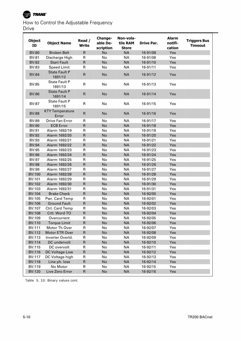
How to Control the Adjustable FrequencyDrive
5-10 TR200 BACnet
ObjectID
Object NameRead /Write
Change-able De-scription
Non-vola-tile RAM
StoreDrive Par.
Alarmnotifi-cation
Triggers BusTimeout
BV:121 10V low R No NA 16-92/17 Yes
BV:122 Brake Overload R No NA 16-92/18 Yes
BV:123 Brake Resistor R No NA 16-92/19 Yes
BV:124 Brake IGBT R No NA 16-92/20 Yes
BV:125 Speed Limit R No NA 16-92/21 Yes
BV:126Serial Communi-
cation Bus FaultR No NA 16-92/22 Yes
BV:127 24V Supply Low R No NA 16-92/23 Yes
BV:128 Line failure R No NA 16-92/24 Yes
BV:129 Current Limit R No NA 16-92/25 Yes
BV:130 Low Temp R No NA 16-92/26 Yes
BV:131 Voltage Limit R No NA 16-92/27 Yes
BV:132 Encoder loss R No NA 16-92/28 Yes
BV:133Output Freq. Lim-
itR No NA 16-92/29 Yes
BV:134 Safe Stop R No NA 16-92/30 Yes
BV:135 Ext. Status R No NA 16-92/31 Yes
BV:136 Start Delayed R No NA 16-93/00 Yes
BV:137 Stop Delayed R No NA 16-93/01 Yes
BV:138 Clock Failure R No NA 16-93/02 Yes
BV:139Fire Mode was
ActiveR No NA 16-93/03 Yes
BV:140Reserved,
P1693/04R No NA 16-93/04 Yes
BV:141 No Flow R No NA 16-93/05 Yes
BV:142 Dry Pump R No NA 16-93/06 Yes
BV:143 End of Curve R No NA 16-93/07 Yes
BV:144 Belt Broken R No NA 16-93/08 Yes
BV:145 Discharge High R No NA 16-93/09 Yes
BV:146Reserved, P
1693/10R No NA 16-93/10 Yes
BV:147Reserved, P
1693/11R No NA 16-93/11 Yes
BV:148Reserved, P
1693/12R No NA 16-93/12 Yes
BV:149Reserved, P
1693/13R No NA 16-93/13 Yes
BV:150Reserved, P
1693/14R No NA 16-93/14 Yes
BV:151Reserved, P
1693/15R No NA 16-93/15 Yes
BV:152Reserved, P
1693/16R No NA 16-93/16 Yes
BV:153 KTY Temperature R No NA 16-93/17 Yes
BV:154 Drive Fan Failure R No NA 16-93/18 Yes
BV:155 ECB Failure R No NA 16-93/19 Yes
Table 5. 11: Binary values cont.
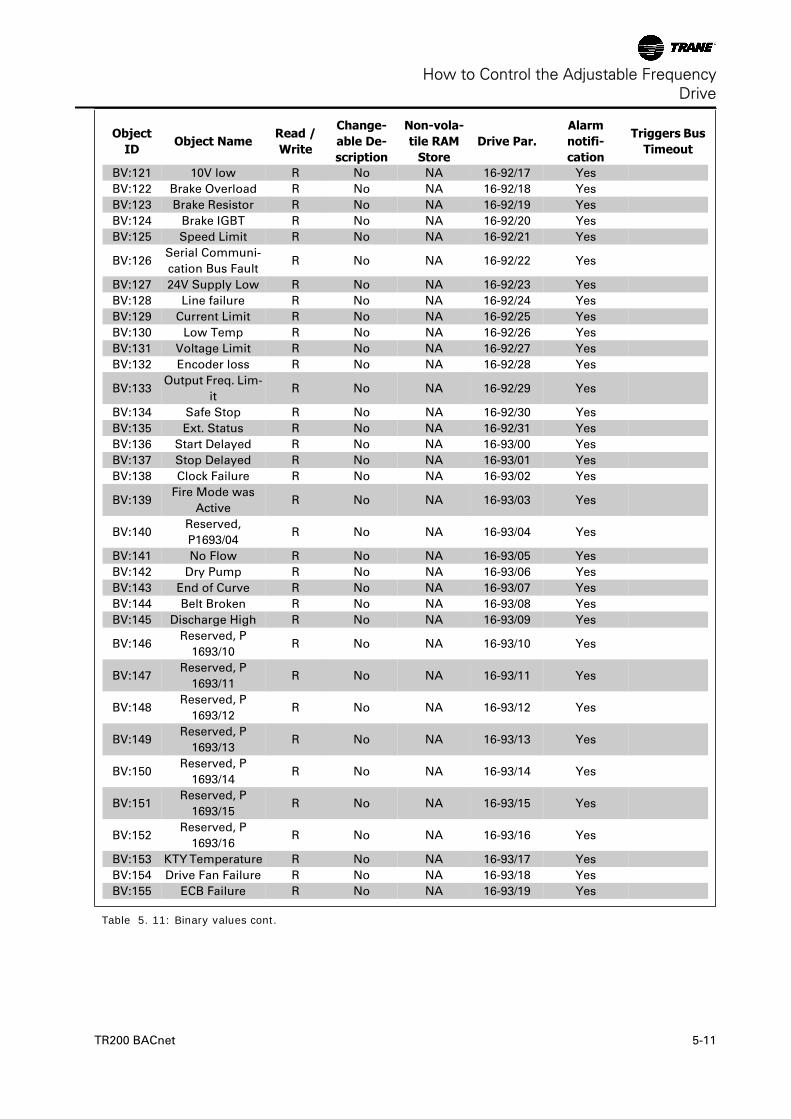
How to Control the Adjustable FrequencyDrive
TR200 BACnet 5-11
ObjectID
Object NameRead /Write
Change-able De-scription
Non-vola-tile RAM
StoreDrive Par.
Alarmnotifi-cation
Triggers BusTimeout
BV:156Reserved, P
1693/20R No NA 16-93/20 Yes
BV:157Reserved, P
1693/21R No NA 16-93/21 Yes
BV:158Reserved, P
1693/22R No NA 16-93/22 Yes
BV:159Reserved, P
1693/23R No NA 16-93/23 Yes
BV:160Reserved, P
1693/24R No NA 16-93/24 Yes
BV:161Reserved, P
1693/25R No NA 16-93/25 Yes
BV:162Reserved, P
1693/26R No NA 16-93/26 Yes
BV:163Reserved, P
1693/27R No NA 16-93/27 Yes
BV:164Reserved, P
1693/28R No NA 16-93/28 Yes
BV:165Reserved, P
1693/29R No NA 16-93/29 Yes
BV:166 PTC Temperature R No NA 16-93/30 Yes
BV:167Reserved, P
1693/31R No NA 16-93/31 Yes
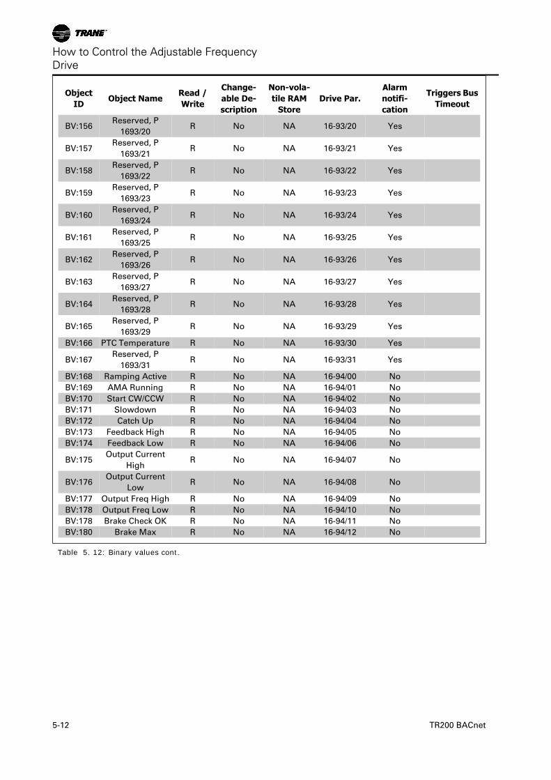
BV:168 Ramping Active R No NA 16-94/00 No
BV:169 AMA Running R No NA 16-94/01 No
BV:170 Start CW/CCW R No NA 16-94/02 No
BV:171 Slowdown R No NA 16-94/03 No
BV:172 Catch Up R No NA 16-94/04 No
BV:173 Feedback High R No NA 16-94/05 No
BV:174 Feedback Low R No NA 16-94/06 No
BV:175Output Current
HighR No NA 16-94/07 No
BV:176Output Current
LowR No NA 16-94/08 No
BV:177 Output Freq High R No NA 16-94/09 No
BV:178 Output Freq Low R No NA 16-94/10 No
BV:178 Brake Check OK R No NA 16-94/11 No
BV:180 Brake Max R No NA 16-94/12 No
Table 5. 12: Binary values cont.
How to Control the Adjustable FrequencyDrive
5-12 TR200 BACnet
ObjectID
Object NameRead /Write
Change-able De-scription
Non-vola-tile RAM
StoreDrive Par.
Alarmnotifi-cation
Triggers BusTimeout
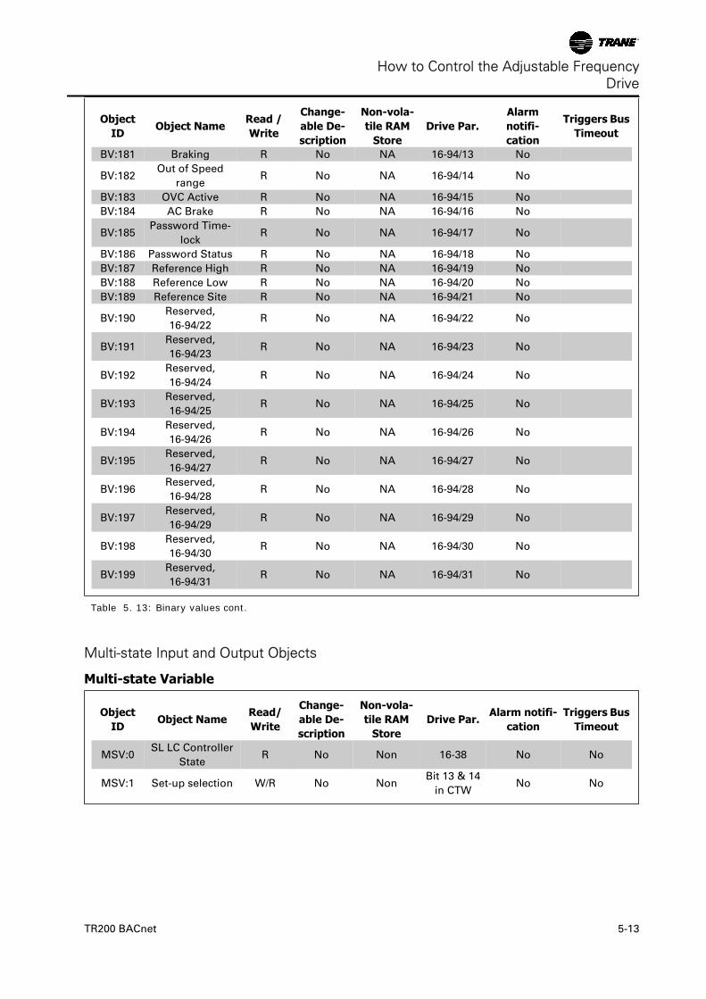
BV:181 Braking R No NA 16-94/13 No
BV:182Out of Speed
rangeR No NA 16-94/14 No
BV:183 OVC Active R No NA 16-94/15 No
BV:184 AC Brake R No NA 16-94/16 No
BV:185Password Time-
lockR No NA 16-94/17 No
BV:186 Password Status R No NA 16-94/18 No
BV:187 Reference High R No NA 16-94/19 No
BV:188 Reference Low R No NA 16-94/20 No
BV:189 Reference Site R No NA 16-94/21 No
BV:190Reserved,
16-94/22R No NA 16-94/22 No
BV:191Reserved,
16-94/23R No NA 16-94/23 No
BV:192Reserved,
16-94/24R No NA 16-94/24 No
BV:193Reserved,
16-94/25R No NA 16-94/25 No
BV:194Reserved,
16-94/26R No NA 16-94/26 No
BV:195Reserved,
16-94/27R No NA 16-94/27 No
BV:196Reserved,
16-94/28R No NA 16-94/28 No
BV:197Reserved,
16-94/29R No NA 16-94/29 No
BV:198Reserved,
16-94/30R No NA 16-94/30 No
BV:199Reserved,
16-94/31R No NA 16-94/31 No
Table 5. 13: Binary values cont.
Multi-state Input and Output Objects
Multi-state Variable
ObjectID
Object NameRead/Write
Change-able De-scription
Non-vola-tile RAM
StoreDrive Par.
Alarm notifi-cation
Triggers BusTimeout
MSV:0SL LC Controller
StateR No Non 16-38 No No
MSV:1 Set-up selection W/R No NonBit 13 & 14
in CTWNo No
How to Control the Adjustable FrequencyDrive
TR200 BACnet 5-13
Mailbox variable
ObjectID
Object NameRead/Write
Change-able De-scription
Non-vola-tile RAM
StoreDrive Par.
Alarm notifi-cation
Triggers BusTimeout
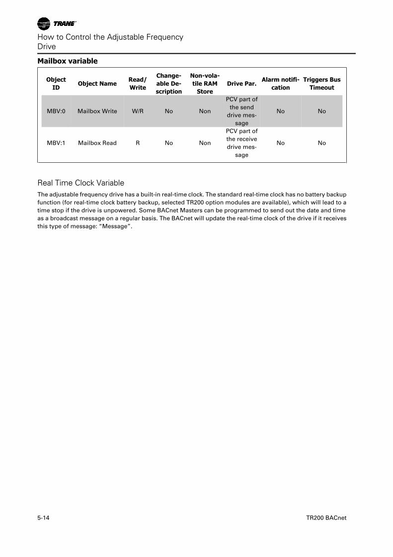
MBV:0 Mailbox Write W/R No Non
PCV part of
the send
drive mes-
sage
No No
MBV:1 Mailbox Read R No Non
PCV part of
the receive
drive mes-
sage
No No
Real Time Clock VariableThe adjustable frequency drive has a built-in real-time clock. The standard real-time clock has no battery backup
function (for real-time clock battery backup, selected TR200 option modules are available), which will lead to a
time stop if the drive is unpowered. Some BACnet Masters can be programmed to send out the date and time
as a broadcast message on a regular basis. The BACnet will update the real-time clock of the drive if it receives
this type of message: “Message”.
How to Control the Adjustable FrequencyDrive
5-14 TR200 BACnet
Adjustable Frequency Drive Feedback to Network
The BACnet option provides several output variables (NVOs) to the network, containing important adjustable
frequency drive, motor and I/O feedback data. The BACnet option transmits bound network variables only and
sends feedback data when there is a change in value.
Influence of the digital input terminals upon the drive control mode, par.8-50 Coasting Select to par.8-56 Preset
Reference Select
The influence of the digital input terminals upon control of the adjustable frequency drive can be programmed
in par.8-50 Coasting Select to par.8-56 Preset Reference Select.
NOTEpar.8-01 Control Site overrules the settings in parameters 8-50 to 8-56 and Terminal 37, Safe Stop overrules anyparameter.
Each of the digital input signals can be programmed to logic AND, logic OR, or to have no relation to the cor-
responding bit in the control word. In this way, a specific control command, i.e., stop / coast, can be initiated by
the serial communication bus only, serial communication bus AND Digital Input, or serial communication bus
OR digital input terminal.
CAUTIONIn order to control the adjustable frequency drive via BACnet, par.8-50 Coasting Select must be set to either Bus [1],or to Logic AND [2] and par.8-01 Control Site must be set to Digital and ctrl. word [0] or Controlword only [2].
More detailed information and examples of logical relationship options are provided in the Troubleshootingchapter.
How to Control the Adjustable FrequencyDrive
TR200 BACnet 5-15
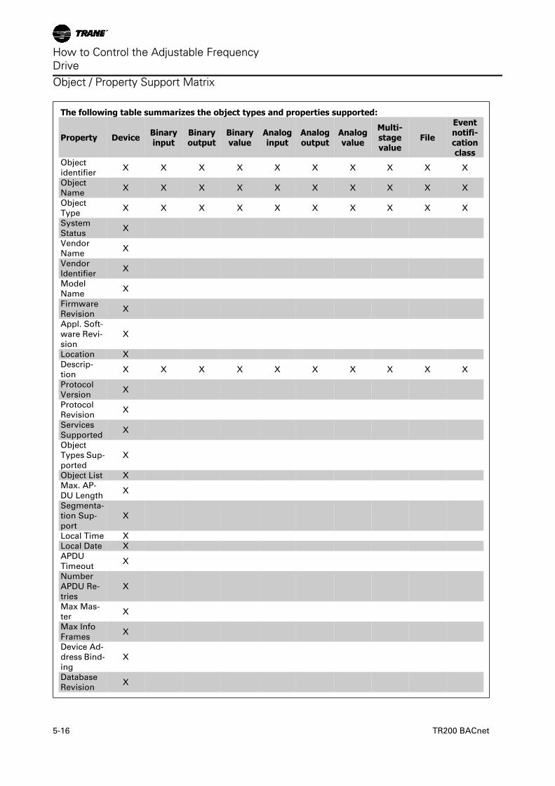
Object / Property Support Matrix
The following table summarizes the object types and properties supported:
Property Device Binaryinput
Binaryoutput
Binaryvalue
Analoginput
Analogoutput
Analogvalue
Multi-stagevalue
File
Eventnotifi-cationclass
Object
identifierX X X X X X X X X X
Object
NameX X X X X X X X X X
Object
TypeX X X X X X X X X X
System
StatusX
Vendor
NameX
Vendor
IdentifierX
Model
NameX
Firmware
RevisionX
Appl. Soft-
ware Revi-
sion
X
Location X
Descrip-
tionX X X X X X X X X X
Protocol
VersionX
Protocol
RevisionX
Services
SupportedX
Object
Types Sup-
ported
X
Object List X
Max. AP-
DU LengthX
Segmenta-
tion Sup-
port
X
Local Time X
Local Date X
APDU
TimeoutX
Number
APDU Re-
tries
X
Max Mas-
terX
Max Info
FramesX
Device Ad-
dress Bind-
ing
X
Database
RevisionX
How to Control the Adjustable FrequencyDrive
5-16 TR200 BACnet
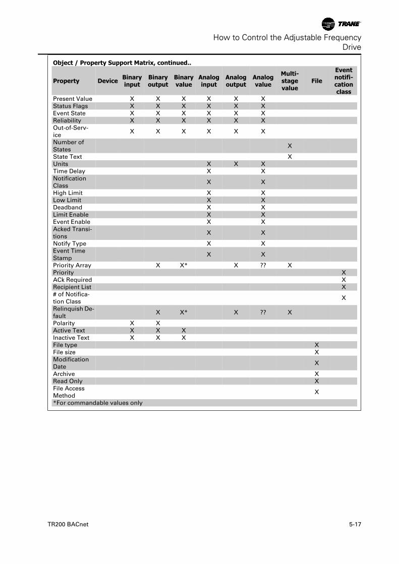
Object / Property Support Matrix, continued..
Property Device Binaryinput
Binaryoutput
Binaryvalue
Analoginput
Analogoutput
Analogvalue
Multi-stagevalue
File
Eventnotifi-cationclass
Present Value X X X X X X
Status Flags X X X X X X
Event State X X X X X X
Reliability X X X X X X
Out-of-Serv-
ice X X X X X X
Number of
States X
State Text X
Units X X X
Time Delay X X
Notification
Class X X
High Limit X X
Low Limit X X
Deadband X X
Limit Enable X X
Event Enable X X
Acked Transi-
tions X X
Notify Type X X
Event Time
Stamp X X
Priority Array X X* X ?? X
Priority X
ACk Required X
Recipient List X
# of Notifica-
tion Class X
Relinquish De-
fault X X* X ?? X
Polarity X X
Active Text X X X
Inactive Text X X X
File type X
File size X
Modification
Date X
Archive X
Read Only X
File Access
Method X
*For commandable values only
How to Control the Adjustable FrequencyDrive
TR200 BACnet 5-17

How to Control the Adjustable FrequencyDrive
5-18 TR200 BACnet
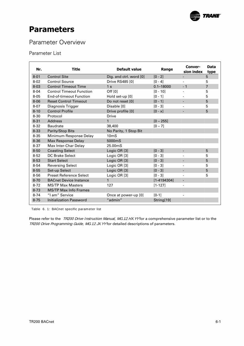
ParametersParameter Overview
Parameter List
Nr. Title Default value RangeConver-
sion indexDatatype
8-01 Control Site Dig. and ctrl. word [0] [0 - 2] - 5
8-02 Control Source Drive RS485 [0] [0 - 4] - 5
8-03 Control Timeout Time 1 s 0.1–18000 - 1 7
8-04 Control Timeout Function Off [0] [0 - 10] - 5
8-05 End-of-timeout Function Hold set-up [0] [0 - 1] - 5
8-06 Reset Control Timeout Do not reset [0] [0 - 1] - 5
8-07 Diagnosis Trigger Disable [0] [0 - 3] - 5
8-10 Control Profile Drive profile [0] [0 - x] - 5
8-30 Protocol Drive
8-31 Address 1 [0 – 255]
8-32 Baudrate 38,400 [0 – 7]
8-33 Parity/Stop Bits No Parity, 1 Stop Bit
8-35 Minimum Response Delay 10mS
8-36 Max Response Delay 5000mS
8-37 Max Inter-Char Delay 25.00mS
8-50 Coasting Select Logic OR [3] [0 - 3] - 5
8-52 DC Brake Select Logic OR [3] [0 - 3] - 5
8-53 Start Select Logic OR [3] [0 - 3] - 5
8-54 Reversing Select Logic OR [3] [0 - 3] - 5
8-55 Set-up Select Logic OR [3] [0 - 3] - 5
8-56 Preset Reference Select Logic OR [3] [0 - 3] - 5
8-70 BACnet Device Instance 1 [1-4194304] -
8-72 MS/TP Max Masters 127 [1-127] -
8-73 MS/TP Max Info Frames
8-74 “I am” Service Once at power-up [0] [0-1] -
8-75 Initialization Password “admin” String[19]
Table 6. 1: BACnet specific parameter list
Please refer to the TR200 Drive Instruction Manual, MG.12.HX.YY for a comprehensive parameter list or to the
TR200 Drive Programming Guide, MG.12.JX.YY for detailed descriptions of parameters.
TR200 BACnet 6-1
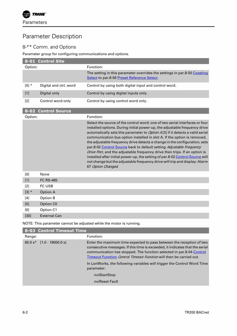
Parameter Description
8-** Comm. and Options Parameter group for configuring communications and options.
8-01 Control SiteOption: Function:
The setting in this parameter overrides the settings in par.8-50 Coasting
Select to par.8-56 Preset Reference Select.
[0] * Digital and ctrl. word Control by using both digital input and control word.
[1] Digital only Control by using digital inputs only.
[2] Control word only Control by using control word only.
8-02 Control SourceOption: Function:
Select the source of the control word: one of two serial interfaces or four
installed options. During initial power-up, the adjustable frequency drive
automatically sets this parameter to Option A [3] if it detects a valid serial
communication bus option installed in slot A. If the option is removed,
the adjustable frequency drive detects a change in the configuration, sets
par.8-02 Control Source back to default setting Adjustable FrequencyDrive Port, and the adjustable frequency drive then trips. If an option is
installed after initial power-up, the setting of par.8-02 Control Source will
not change but the adjustable frequency drive will trip and display: Alarm
67 Option Changed.
[0] None
[1] FC RS-485
[2] FC USB
[3] * Option A
[4] Option B
[5] Option C0
[6] Option C1
[30] External Can
NOTE: This parameter cannot be adjusted while the motor is running.
8-03 Control Timeout TimeRange: Function:
60.0 s* [1.0 - 18000.0 s] Enter the maximum time expected to pass between the reception of two
consecutive messages. If this time is exceeded, it indicates that the serial
communication has stopped. The function selected in par.8-04 Control
Timeout Function Control Timeout Function will then be carried out.
In LonWorks, the following variables will trigger the Control Word Time
parameter:
nviStartStop
nviReset Fault
Parameters
6-2 TR200 BACnet
nviControlWord
nviDrvSpeedStpt
nviRefPcnt
nviRefHz
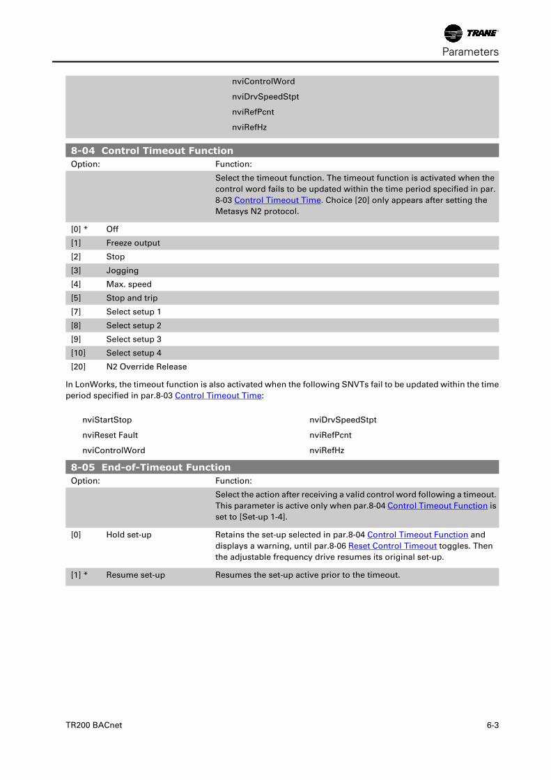
8-04 Control Timeout FunctionOption: Function:
Select the timeout function. The timeout function is activated when the
control word fails to be updated within the time period specified in par.
8-03 Control Timeout Time. Choice [20] only appears after setting the
Metasys N2 protocol.
[0] * Off
[1] Freeze output
[2] Stop
[3] Jogging
[4] Max. speed
[5] Stop and trip
[7] Select setup 1
[8] Select setup 2
[9] Select setup 3
[10] Select setup 4
[20] N2 Override Release
In LonWorks, the timeout function is also activated when the following SNVTs fail to be updated within the time
period specified in par.8-03 Control Timeout Time:
nviStartStop
nviReset Fault
nviControlWord
nviDrvSpeedStpt
nviRefPcnt
nviRefHz
8-05 End-of-Timeout FunctionOption: Function:
Select the action after receiving a valid control word following a timeout.
This parameter is active only when par.8-04 Control Timeout Function is
set to [Set-up 1-4].
[0] Hold set-up Retains the set-up selected in par.8-04 Control Timeout Function and
displays a warning, until par.8-06 Reset Control Timeout toggles. Then
the adjustable frequency drive resumes its original set-up.
[1] * Resume set-up Resumes the set-up active prior to the timeout.
Parameters
TR200 BACnet 6-3
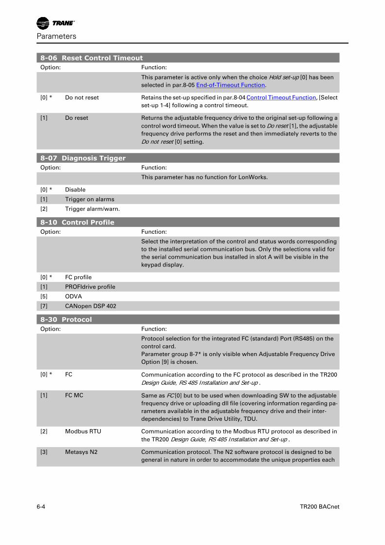
8-06 Reset Control TimeoutOption: Function:
This parameter is active only when the choice Hold set-up [0] has been
selected in par.8-05 End-of-Timeout Function.
[0] * Do not reset Retains the set-up specified in par.8-04 Control Timeout Function, [Select
set-up 1-4] following a control timeout.
[1] Do reset Returns the adjustable frequency drive to the original set-up following a
control word timeout. When the value is set to Do reset [1], the adjustable
frequency drive performs the reset and then immediately reverts to the
Do not reset [0] setting.
8-07 Diagnosis TriggerOption: Function:
This parameter has no function for LonWorks.
[0] * Disable
[1] Trigger on alarms
[2] Trigger alarm/warn.
8-10 Control ProfileOption: Function:
Select the interpretation of the control and status words corresponding
to the installed serial communication bus. Only the selections valid for
the serial communication bus installed in slot A will be visible in the
keypad display.
[0] * FC profile
[1] PROFIdrive profile
[5] ODVA
[7] CANopen DSP 402
8-30 ProtocolOption: Function:
Protocol selection for the integrated FC (standard) Port (RS485) on the
control card.
Parameter group 8-7* is only visible when Adjustable Frequency Drive
Option [9] is chosen.
[0] * FC Communication according to the FC protocol as described in the TR200
Design Guide, RS 485 Installation and Set-up .
[1] FC MC Same as FC [0] but to be used when downloading SW to the adjustable
frequency drive or uploading dll file (covering information regarding pa-
rameters available in the adjustable frequency drive and their inter-
dependencies) to Trane Drive Utility, TDU.
[2] Modbus RTU Communication according to the Modbus RTU protocol as described in
the TR200 Design Guide, RS 485 Installation and Set-up .
[3] Metasys N2 Communication protocol. The N2 software protocol is designed to be
general in nature in order to accommodate the unique properties each
Parameters
6-4 TR200 BACnet
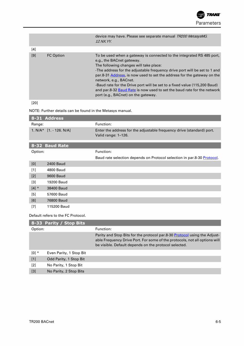
device may have. Please see separate manual TR200 MetasysMG.12.NX.YY.
[4]
[9] FC Option To be used when a gateway is connected to the integrated RS 485 port,
e.g., the BACnet gateway.
The following changes will take place:
-The address for the adjustable frequency drive port will be set to 1 and
par.8-31 Address, is now used to set the address for the gateway on the
network, e.g., BACnet.
-Baud rate for the Drive port will be set to a fixed value (115,200 Baud)
and par.8-32 Baud Rate is now used to set the baud rate for the network
port (e.g., BACnet) on the gateway.
[20]
NOTE: Further details can be found in the Metasys manual.
8-31 AddressRange: Function:
1. N/A* [1. - 126. N/A] Enter the address for the adjustable frequency drive (standard) port.
Valid range: 1–126.
8-32 Baud RateOption: Function:
Baud rate selection depends on Protocol selection in par.8-30 Protocol.
[0] 2400 Baud
[1] 4800 Baud
[2] 9600 Baud
[3] 19200 Baud
[4] * 38400 Baud
[5] 57600 Baud
[6] 76800 Baud
[7] 115200 Baud
Default refers to the FC Protocol.
8-33 Parity / Stop BitsOption: Function:
Parity and Stop Bits for the protocol par.8-30 Protocol using the Adjust-
able Frequency Drive Port. For some of the protocols, not all options will
be visible. Default depends on the protocol selected.
[0] * Even Parity, 1 Stop Bit
[1] Odd Parity, 1 Stop Bit
[2] No Parity, 1 Stop Bit
[3] No Parity, 2 Stop Bits
Parameters
TR200 BACnet 6-5
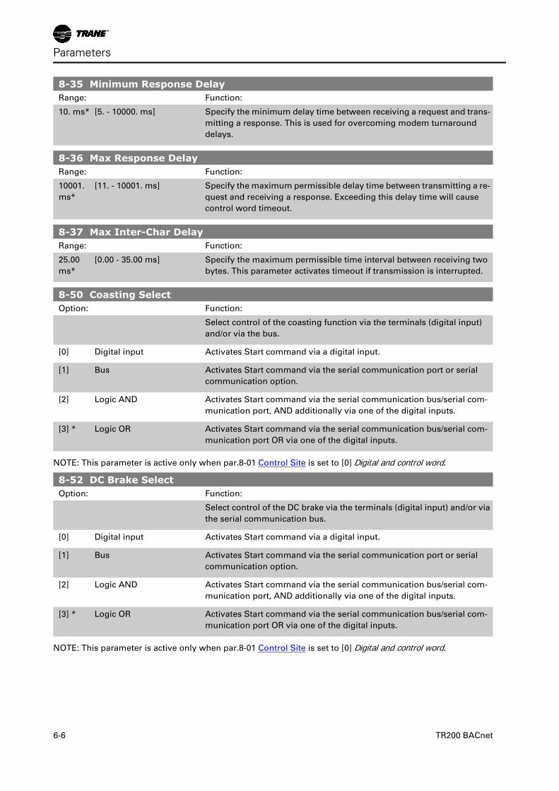
8-35 Minimum Response DelayRange: Function:
10. ms* [5. - 10000. ms] Specify the minimum delay time between receiving a request and trans-
mitting a response. This is used for overcoming modem turnaround
delays.
8-36 Max Response DelayRange: Function:
10001.
ms*
[11. - 10001. ms] Specify the maximum permissible delay time between transmitting a re-
quest and receiving a response. Exceeding this delay time will cause
control word timeout.
8-37 Max Inter-Char DelayRange: Function:
25.00
ms*
[0.00 - 35.00 ms] Specify the maximum permissible time interval between receiving two
bytes. This parameter activates timeout if transmission is interrupted.
8-50 Coasting SelectOption: Function:
Select control of the coasting function via the terminals (digital input)
and/or via the bus.
[0] Digital input Activates Start command via a digital input.
[1] Bus Activates Start command via the serial communication port or serial
communication option.
[2] Logic AND Activates Start command via the serial communication bus/serial com-
munication port, AND additionally via one of the digital inputs.
[3] * Logic OR Activates Start command via the serial communication bus/serial com-
munication port OR via one of the digital inputs.
NOTE: This parameter is active only when par.8-01 Control Site is set to [0] Digital and control word.
8-52 DC Brake SelectOption: Function:
Select control of the DC brake via the terminals (digital input) and/or via
the serial communication bus.
[0] Digital input Activates Start command via a digital input.
[1] Bus Activates Start command via the serial communication port or serial
communication option.
[2] Logic AND Activates Start command via the serial communication bus/serial com-
munication port, AND additionally via one of the digital inputs.
[3] * Logic OR Activates Start command via the serial communication bus/serial com-
munication port OR via one of the digital inputs.
NOTE: This parameter is active only when par.8-01 Control Site is set to [0] Digital and control word.
Parameters
6-6 TR200 BACnet
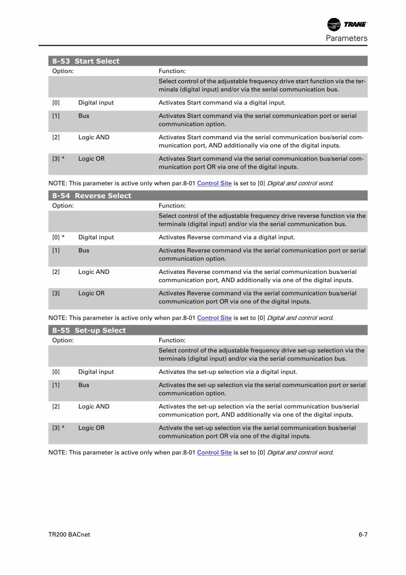
8-53 Start SelectOption: Function:
Select control of the adjustable frequency drive start function via the ter-
minals (digital input) and/or via the serial communication bus.
[0] Digital input Activates Start command via a digital input.
[1] Bus Activates Start command via the serial communication port or serial
communication option.
[2] Logic AND Activates Start command via the serial communication bus/serial com-
munication port, AND additionally via one of the digital inputs.
[3] * Logic OR Activates Start command via the serial communication bus/serial com-
munication port OR via one of the digital inputs.
NOTE: This parameter is active only when par.8-01 Control Site is set to [0] Digital and control word.
8-54 Reverse SelectOption: Function:
Select control of the adjustable frequency drive reverse function via the
terminals (digital input) and/or via the serial communication bus.
[0] * Digital input Activates Reverse command via a digital input.
[1] Bus Activates Reverse command via the serial communication port or serial
communication option.
[2] Logic AND Activates Reverse command via the serial communication bus/serial
communication port, AND additionally via one of the digital inputs.
[3] Logic OR Activates Reverse command via the serial communication bus/serial
communication port OR via one of the digital inputs.
NOTE: This parameter is active only when par.8-01 Control Site is set to [0] Digital and control word.
8-55 Set-up SelectOption: Function:
Select control of the adjustable frequency drive set-up selection via the
terminals (digital input) and/or via the serial communication bus.
[0] Digital input Activates the set-up selection via a digital input.
[1] Bus Activates the set-up selection via the serial communication port or serial
communication option.
[2] Logic AND Activates the set-up selection via the serial communication bus/serial
communication port, AND additionally via one of the digital inputs.
[3] * Logic OR Activate the set-up selection via the serial communication bus/serial
communication port OR via one of the digital inputs.
NOTE: This parameter is active only when par.8-01 Control Site is set to [0] Digital and control word.
Parameters
TR200 BACnet 6-7
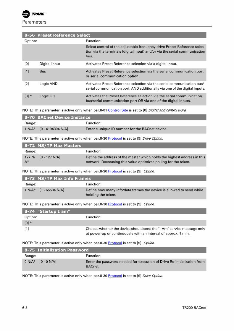
8-56 Preset Reference SelectOption: Function:
Select control of the adjustable frequency drive Preset Reference selec-
tion via the terminals (digital input) and/or via the serial communication
bus.
[0] Digital input Activates Preset Reference selection via a digital input.
[1] Bus Activates Preset Reference selection via the serial communication port
or serial communication option.
[2] Logic AND Activates Preset Reference selection via the serial communication bus/
serial communication port, AND additionally via one of the digital inputs.
[3] * Logic OR Activates the Preset Reference selection via the serial communication
bus/serial communication port OR via one of the digital inputs.
NOTE: This parameter is active only when par.8-01 Control Site is set to [0] Digital and control word.
8-70 BACnet Device InstanceRange: Function:
1 N/A* [0 - 4194304 N/A] Enter a unique ID number for the BACnet device.
NOTE: This parameter is active only when par.8-30 Protocol is set to [9] Drive Option.
8-72 MS/TP Max MastersRange: Function:
127 N/
A*
[0 - 127 N/A] Define the address of the master which holds the highest address in this
network. Decreasing this value optimizes polling for the token.
NOTE: This parameter is active only when par.8-30 Protocol is set to [9] Option.
8-73 MS/TP Max Info FramesRange: Function:
1 N/A* [1 - 65534 N/A] Define how many info/data frames the device is allowed to send while
holding the token.
NOTE: This parameter is active only when par.8-30 Protocol is set to [9] Option.
8-74 "Startup I am"Option: Function:
[0] *
[1] Choose whether the device should send the "I-Am" service message only
at power-up or continuously with an interval of approx. 1 min.
NOTE: This parameter is active only when par.8-30 Protocol is set to [9] Option.
8-75 Initialization PasswordRange: Function:
0 N/A* [0 - 0 N/A] Enter the password needed for execution of Drive Re-initialization from
BACnet.
NOTE: This parameter is active only when par.8-30 Protocol is set to [9] Drive Option.
Parameters
6-8 TR200 BACnet
TroubleshootingAlarm, Warning and Extended Status Word
Alarm and Warning Messages
GeneralThere is a clear distinction between alarms and warnings. In the event of an alarm, the adjustable frequency
drive will enter a fault condition. After the cause for the alarm has been cleared, the master must acknowledge
the alarm message in order to start operation of the adjustable frequency drive again. A warning, on the other
hand, may appear when a warning condition arises, then disappear when conditions return to normal without
interfering with the process.
Alarm Word and Warning Word are shown on the display in Hex format. If there is more than one warning or
alarm, a sum of all warnings or alarms will be shown. Warning Word and Alarm Word are displayed in par.
16-90 to 16-95. For more information on the individual alarms and warnings, please refer to: TR200 DesignGuide.
WarningsAll warnings within the adjustable frequency drive are represented by a single bit within a warning word. A
warning word is always an action parameter. Bit status FALSE [0] means no warning, while bit status TRUE [1]
means warning. Each bit status has a corresponding text string message. In addition to the Warning Word
message, the master will also be notified via a change to bit 7 in the status word.
AlarmsFollowing an alarm message the adjustable frequency drive will enter a fault condition. Only after the fault has
been rectified and the master has acknowledged the alarm message by setting bit 3 in the Control Word, can
the adjustable frequency drive resume operation. All alarms within the TR200 are represented by a single bit
within an alarm word. An alarm word is always an action parameter. Bit status FALSE [0] means no alarm, while
bit status TRUE [1] means alarm.
TR200 BACnet 7-1
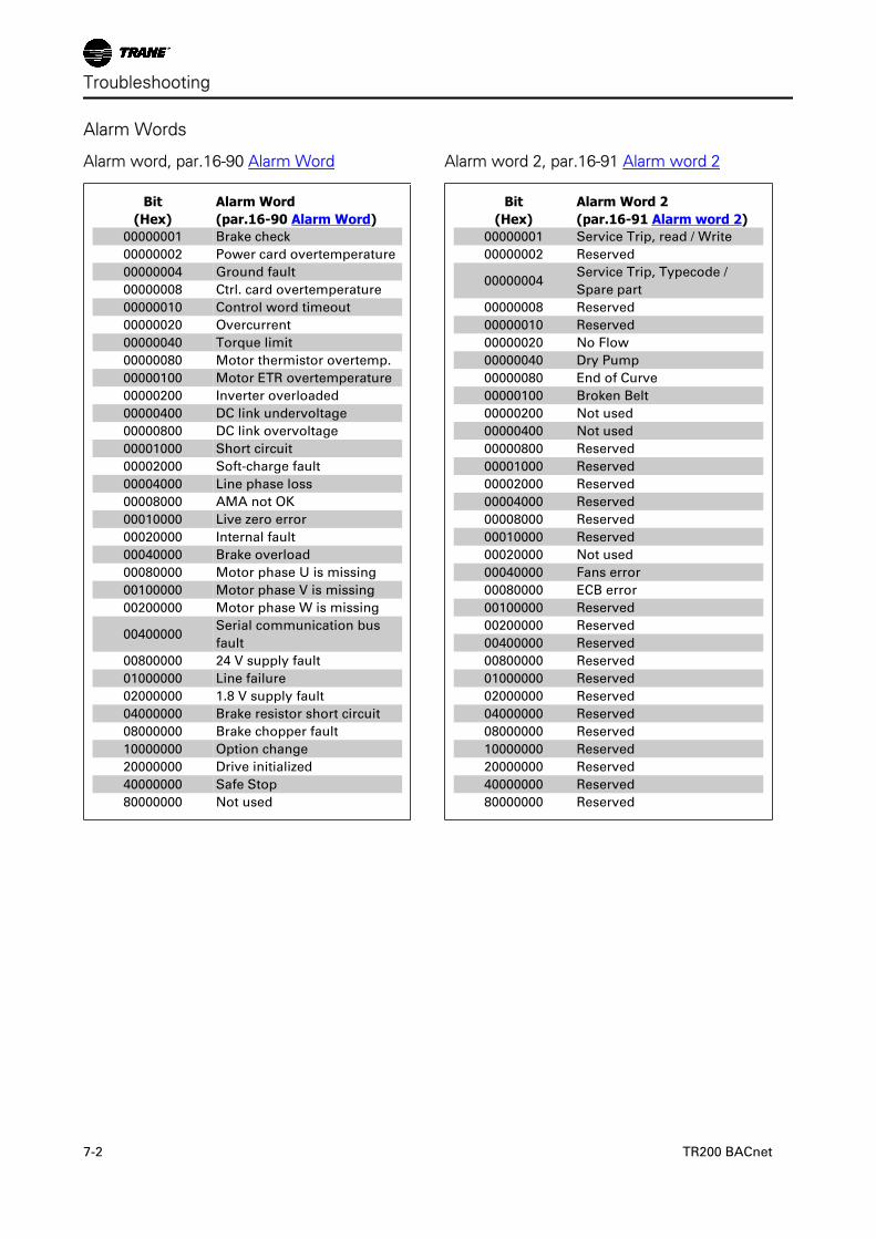
Alarm Words
Alarm word, par.16-90 Alarm Word
Bit(Hex)
Alarm Word(par.16-90 Alarm Word)
00000001 Brake check
00000002 Power card overtemperature
00000004 Ground fault
00000008 Ctrl. card overtemperature
00000010 Control word timeout
00000020 Overcurrent
00000040 Torque limit
00000080 Motor thermistor overtemp.
00000100 Motor ETR overtemperature
00000200 Inverter overloaded
00000400 DC link undervoltage
00000800 DC link overvoltage
00001000 Short circuit
00002000 Soft-charge fault
00004000 Line phase loss
00008000 AMA not OK
00010000 Live zero error
00020000 Internal fault
00040000 Brake overload
00080000 Motor phase U is missing
00100000 Motor phase V is missing
00200000 Motor phase W is missing
00400000Serial communication bus
fault
00800000 24 V supply fault
01000000 Line failure
02000000 1.8 V supply fault
04000000 Brake resistor short circuit
08000000 Brake chopper fault
10000000 Option change
20000000 Drive initialized
40000000 Safe Stop
80000000 Not used
Alarm word 2, par.16-91 Alarm word 2
Bit(Hex)
Alarm Word 2(par.16-91 Alarm word 2)
00000001 Service Trip, read / Write
00000002 Reserved
00000004Service Trip, Typecode /
Spare part
00000008 Reserved
00000010 Reserved
00000020 No Flow
00000040 Dry Pump
00000080 End of Curve
00000100 Broken Belt
00000200 Not used
00000400 Not used
00000800 Reserved
00001000 Reserved
00002000 Reserved
00004000 Reserved
00008000 Reserved
00010000 Reserved
00020000 Not used
00040000 Fans error
00080000 ECB error
00100000 Reserved
00200000 Reserved
00400000 Reserved
00800000 Reserved
01000000 Reserved
02000000 Reserved
04000000 Reserved
08000000 Reserved
10000000 Reserved
20000000 Reserved
40000000 Reserved
80000000 Reserved
Troubleshooting
7-2 TR200 BACnet
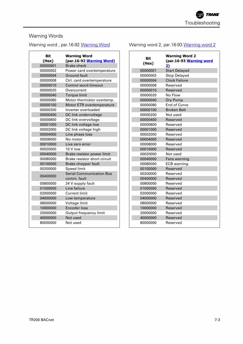
Warning Words
Warning word , par.16-92 Warning Word
Bit(Hex)
Warning Word(par.16-92 Warning Word)
00000001 Brake check
00000002 Power card overtemperature
00000004 Ground fault
00000008 Ctrl. card overtemperature
00000010 Control word timeout
00000020 Overcurrent
00000040 Torque limit
00000080 Motor thermistor overtemp.
00000100 Motor ETR overtemperature
00000200 Inverter overloaded
00000400 DC link undervoltage
00000800 DC link overvoltage
00001000 DC link voltage low
00002000 DC link voltage high
00004000 Line phase loss
00008000 No motor
00010000 Live zero error
00020000 10 V low
00040000 Brake resistor power limit
00080000 Brake resistor short circuit
00100000 Brake chopper fault
00200000 Speed limit
00400000Serial Communication Bus
comm. fault
00800000 24 V supply fault
01000000 Line failure
02000000 Current limit
04000000 Low temperature
08000000 Voltage limit
10000000 Encoder loss
20000000 Output frequency limit
40000000 Not used
80000000 Not used
Warning word 2, par.16-93 Warning word 2
Bit(Hex)
Warning Word 2(par.16-93 Warning word2)
00000001 Start Delayed
00000002 Stop Delayed
00000004 Clock Failure
00000008 Reserved
00000010 Reserved
00000020 No Flow
00000040 Dry Pump
00000080 End of Curve
00000100 Broken Belt
00000200 Not used
00000400 Reserved
00000800 Reserved
00001000 Reserved
00002000 Reserved
00004000 Reserved
00008000 Reserved
00010000 Reserved
00020000 Not used
00040000 Fans warning
00080000 ECB warning
00100000 Reserved
00200000 Reserved
00400000 Reserved
00800000 Reserved
01000000 Reserved
02000000 Reserved
04000000 Reserved
08000000 Reserved
10000000 Reserved
20000000 Reserved
40000000 Reserved
80000000 Reserved
Troubleshooting
TR200 BACnet 7-3
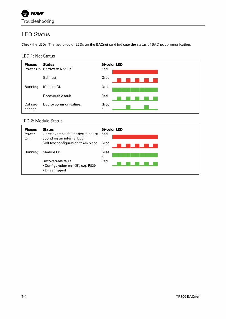
LED Status
Check the LEDs. The two bi-color LEDs on the BACnet card indicate the status of BACnet communication.
LED 1: Net Status
Phases Status Bi-color LEDPower On. Hardware Not OK Red
Self test Gree
n ▂█▂█▂█▂█▂█ Running Module OK Gree
n ██████████ Recoverable fault Red
Data ex-
change
Device communicating. Gree
n
LED 2: Module Status
Phases Status Bi-color LEDPower
On.
Unrecoverable fault drive is not re-
sponding on internal bus
Red
Self test configuration takes place Gree
n ▂█▂█▂█▂█▂█ Running Module OK Gree
n ██████████ Recoverable fault
• Configuration not OK, e.g, P830
• Drive tripped
Red
Troubleshooting
7-4 TR200 BACnet

Rev. 2009-06-18130R0451 MG12L122
*MG12L122*
BACnet® Option Module Instruction Manual
June 2009
TR200
BAS-SVX24A-EN
BAS-SVX24A-EN
Trane has a policy of continous product and product data improvement and reserves the right tochange design and specifications without notice.
www.trane.com
For more information, contact your local Traneoffice or e-mail us at [email protected]
Literature Order Number BAS-SVX24B-EN
Date November 2009
Supersedes BAS-SVX24A