
Backplanes, technical specifications - Pixus Technologies 2.1 (hot swap spec.) IEEE 1101.1,...
10
Page 60 Pixus offers an extensive range of powerful backplanes for Compact- PCI. ● Modular construction facilitates expansion up to a maximum of 21 slots ● Connection between segments via cPCI and/or H.110 bridge modules ● Power input via ATX-compatible connectors or screw terminal ● Additional 2 x 3 Mate-N-Lock connector for 48 V with H.110 back- plane ● Optional development of customer-specific Monolithic backplanes ● 8 layer ● System slot on right (left upon request) Modular assembly The Ripac backplanes in 32 or 64 bit versions allow the configura- tion of cPCI systems from 2 – 21 slots. This is possible due to the modular design of the backplanes and connection of the individual segments via cPCI or H.110 bridge modules. Each backplane segment contains between 2 and 8 slots and operates in stand- alone mode in conjunction with a CPU board and a power supply unit. For assembling larger systems, several segments may be joined together via PCI bridge modules fitted at the rear. In such cases, only one of the segments will run in the system slot with a CPU board. The remaining segments will have a subordinate status with- out CPU boards. However, the first slot on the right of the backplane is available for a standard 32 or 64 bit CompactPCI host CPU. Technical specifications CPU slot A single 3 U or 6 U CPU board with 32 or 64 bits is required for each system. The system slot on the right-hand side ensures that 2-slot or wider system boards do not conceal other slots, thus rendering them unusable. Available slots Each backplane contains two to eight 3 U or 6 U slots (32 or 64 bit). Data transfer rate 132/264 MBytes for 32/64 bit version +5 V, 33 MHz PCI bus interface 264/512 MBytes for 32/64 bit version +3.3 V, 66 MHz (max. 5 slots) PCI bus interface PCI bridges Single backplanes do not require bridges. For each additional backplane, however, a bridge fitted at the rear is required. Power supply Voltage supply via one or more ATX connectors. Control connector Each backplane has a control connector where +3.3, +5, ±12 V voltages may be picked off, e.g. for the connection of power LEDs. I/O modules for J3 – J5 I/O modules can be connected at the rear of each slot. Standards ● PCI 2.1 (PCI specification) ● PICMG 2.0 (CompactPCI spec.) ● PICMG 2.1 (hot swap spec.) ● IEEE 1101.1, mechanics ● IEEE 1101.10, mechanics ● IEEE 1101.11, mechanics Power Backplane Modular Backplane Beginning Segment Middle Segment End Segment H.110 Bridge (RP1150) PCI-PCI Bridge (RP113x) h o s t s l o t As viewed from rear of subrack cPCI Backplanes, technical specifications
-
Upload
nguyentuyen -
Category
Documents
-
view
220 -
download
1
Transcript of Backplanes, technical specifications - Pixus Technologies 2.1 (hot swap spec.) IEEE 1101.1,...

Page 60
Pixus offers an extensive range of powerful backplanes for Compact-PCI.● Modular construction facilitates expansion up to a maximum of
21 slots● Connection between segments via cPCI and/or H.110 bridge modules ● Power input via ATX-compatible connectors or screw terminal● Additional 2 x 3 Mate-N-Lock connector for 48 V with H.110 back-
plane● Optional development of customer-specific Monolithic backplanes● 8 layer ● System slot on right (left upon request)
Modular assemblyThe Ripac backplanes in 32 or 64 bit versions allow the configura-tion of cPCI systems from 2 – 21 slots. This is possible due to the modular design of the backplanes and connection of the individual segments via cPCI or H.110 bridge modules. Each backplane segment contains between 2 and 8 slots and operates in stand-alone mode in conjunction with a CPU board and a power supply unit.
For assembling larger systems, several segments may be joined together via PCI bridge modules fitted at the rear. In such cases, only one of the segments will run in the system slot with a CPU board. The remaining segments will have a subordinate status with-out CPU boards. However, the first slot on the right of the backplane is available for a standard 32 or 64 bit CompactPCI host CPU.
Technical specificationsCPU slotA single 3 U or 6 U CPU board with 32 or 64 bits is required for each system. The system slot on the right-hand side ensures that 2-slot or wider system boards do not conceal other slots, thus rendering them unusable.Available slotsEach backplane contains two to eight 3 U or 6 U slots (32 or 64 bit).Data transfer rate132/264 MBytes for 32/64 bit version +5 V, 33 MHz PCI bus interface 264/512 MBytes for 32/64 bit version +3.3 V, 66 MHz (max. 5 slots) PCI bus interface PCI bridgesSingle backplanes do not require bridges. For each additional backplane, however, a bridge fitted at the rear is required.
Power supplyVoltage supply via one or more ATX connectors.Control connectorEach backplane has a control connector where +3.3, +5, ±12 V voltages may be picked off, e.g. for the connection of power LEDs.I/O modules for J3 – J5I/O modules can be connected at the rear of each slot.Standards ● PCI 2.1 (PCI specification)● PICMG 2.0 (CompactPCI spec.)● PICMG 2.1 (hot swap spec.)● IEEE 1101.1, mechanics● IEEE 1101.10, mechanics● IEEE 1101.11, mechanics
PowerBackplane
ModularBackplane
BeginningSegment
MiddleSegment
EndSegment
H.110 Bridge (RP1150)
PCI-PCI Bridge (RP113x)
host
slot
As viewed from rear of subrack
cPCI
Backplanes, technical specifications

Page 61
32-bit pin assignmentP2 connector9) P1 connector9)
Pin Z6) A B C D E F22 GND GA45) GA35) GA25) GA15) GAO5) GND21 GND BP(I/O) BP(I/O) BP(I/O) BP(I/O) BP(I/O) GND20 GND BP(I/O) BP(I/O) BP(I/O) BP(I/O) BP(I/O) GND19 GND BP(I/O) BP(I/O) BP(I/O) BP(I/O) BP(I/O) GND18 GND BP(I/O) BP(I/O) BP(I/O) BP(I/O) BP(I/O) GND17 GND BP(I/O) BP(I/O) BP(I/O) BP(I/O) BP(I/O) GND16 GND BP(I/O) BP(I/O) BP(I/O) BP(I/O) BP(I/O) GND15 GND BP(I/O) BP(I/O) BP(I/O) BP(I/O) BP(I/O) GND14 GND BP(I/O) BP(I/O) BP(I/O) BP(I/O) BP(I/O) GND13 GND BP(I/O) BP(I/O) BP(I/O) BP(I/O) BP(I/O) GND12 GND BP(I/O) BP(I/O) BP(I/O) BP(I/O) BP(I/O) GND11 GND BP(I/O) BP(I/O) BP(I/O) BP(I/O) BP(I/O) GND10 GND BP(I/O) BP(I/O) BP(I/O) BP(I/O) BP(I/O) GND9 GND BP(I/O) BP(I/O) BP(I/O) BP(I/O) BP(I/O) GND8 GND BP(I/O) BP(I/O) BP(I/O) BP(I/O) BP(I/O) GND7 GND BP(I/O) BP(I/O) BP(I/O) BP(I/O) BP(I/O) GND6 GND BP(I/O) BP(I/O) BP(I/O) BP(I/O) BP(I/O) GND5 GND BP(I/O) BP(I/O) BP(I/O) BP(I/O) BP(I/O) GND4 GND BP(I/O) BP(I/O) BP(I/O) BP(I/O) BP(I/O) GND3 GND BP(I/O) BP(I/O) BP(I/O) BP(I/O) BP(I/O) GND2 GND BP(I/O) BP(I/O) BP(I/O) BP(I/O) BP(I/O) GND1 GND BP(I/O) BP(I/O) BP(I/O) BP(I/O) BP(I/O) GND
Pin Z6) A B C D E F25 GND 5 V REQ64# ENUM# 3.3 V 5 V GND24 GND AD(1) 5 V V(I/O)3) AD(O) ACK64# GND23 GND 3.3 V AD(4) AD(3) 5 V AD(2) GND22 GND AD(7) GND 3.3 V AD(6) AD(5) GND21 GND 3.3 V AD(9) AD(8) M66EN3) C/BE(0)# GND20 GND AD(12) GND V(I/O)3) AD(11) AD(10) GND19 GND 3.3 V AD(15) AD(14) GND AD(13) GND18 GND SERR# GND 3.3 V PAR C/BE(1)# GND17 GND 3.3 V SDONE SBQ# GND PERR# GND16 GND DEVSEL GND V(I/O)1)3) STOP# LOCK# GND15 GND 3.3 V FRAME# IRDY GND2) TRDY# GND
DNGAERA YEK41 – 2111 GND AD(18) AD(17) AD(16) GND C/BE(2)# GND10 GND AD(21) GND 3.3 V AD(20) AD(19) GND9 GND C/BE(3)# IDSEL AD(23) GND AD(22) GND8 GND AD(26) GND V(I/O)3) AD(25) AD(24) GND7 GND AD(30) AD(29) AD(28) GND AD(27) GND6 GND REQ# GND 3.3 V CLK AD(31) GND5 GND BRSVP1A5 BRSVP1B5 RST# GND GNT# GND4 GND BRSVP1A4 GND V(I/O)3) INTP INTS GND3 GND INTA# INTB# INTC# 5 V INTD# GND2 GND TCK 5 V TMS TDO TDI GND1 GND 5 V –12 V TRST# +12 V 5 V GND
32-bit and 64-bit backplane – Technical specifications:The cPCI specifications define both 32-bit and 64-bit versions. Both versions may be implemented on a 3 U daughterboard. However, the 32-bit version allows the complete P2/J2 connector to be used for user-defined I/O signals (slots 2 – 8). Slot 1 (system slot) uses separate P2/J2 pins for functions such as clock, arbitration, (grant/requests) and other system functions. These pins are printed in bold in the table. In 32-bit systems the P2/J2 connector may optionally be populated at the rear with 16 mm long pins and a transfer frame. Signals can be picked off or I/O boards connected at the rear.
64-bit CompactPCI pin assignments – Technical specifications:With the 64-bit CompactPCI, both P1 and P2 connectors are fully assigned with signals. User-defined I/O signal pins are not availa-ble. I/O signals are only availabl e with 6 U boards on connectors P3, P4 and P5.
64-bit pin assignmentP2 connector9) P1 connector9)
Pin Z7) A B C D E F22 GND GA46) GA36) GA26) GA16) GAO6) GND21 GND CLK6 GND RSV RSV RSV GND20 GND CLK5 GND RSV GND8) RSV GND19 GND GND GND8) RSV RSV RSV GND18 GND BRSVP2A18 BRSVP2B18 BRSVP2C18 GND8) BRSVP2E18 GND17 GND BRSVP2A17 GND8) PRST# REQ6# GNT6# GND16 GND BRSVP2A16 BRSVP2B16 DEG# GND8) BRSVP2E16 GND15 GND BRSVP2A15 GND FAL# REQ5# GNT5# GND14 GND AD(35) AD(34) AD(33) GND AD(32) GND13 GND AD(38) GND V(I/O)3) AD(37) AD(36) GND12 GND AD(42) AD(41) AD(40) GND AD(39) GND11 GND AD(45) GND V(I/O)3) AD(44) AD(43) GND10 GND AD(49) AD(48) AD(47) GND AD(46) GND9 GND AD(52) GND V(I/O)3) AD(51) AD(50) GND8 GND AD(56) AD(55) AD(54) GND AD(53) GND7 GND AD(59) GND V(I/O)3) AD(58) AD(57) GND6 GND AD(63) AD(62) AD(61) GND AD(60) GND5 GND C/BE(5)# GND V(I/O)3) C/BE(4)# PAR64 GND4 GND V(I/O)3) BRSVP2B4 C/BE(7)# – C/BE(6)# GND
33) GND CLK4 GND GNT3# – GNT4# GND23) GND CLK2 CLK3 SYSEN#4) – REQ3# GND13) GND CLK1 GND REQ1# – REQ2# GND
Pin Z7) A B C D E F25 GND 5 V REQ64# ENUM# 3.3 V 5 V GND24 GND AD(1) 5 V V(I/O)3) AD(0) ACK64# GND23 GND 3.3 V AD(4) AD(3) 5 V AD(2) GND22 GND AD(7) GND 3.3 V AD(6) AD(5) GND21 GND 3.3 V AD(9) AD(8) M66EN4)5) C/BE(0) GND20 GND AD(12) GND V(I/O)3) AD(11) AD(10) GND19 GND 3.3 V AD(15) AD(14) GND AD(13) GND18 GND SERR# GND 3.3 V PAR C/BE(1)# GND17 GND 3.3 V SDONE SBO# GND PERR# GND16 GND DEVSEL# GND V(I/O)1)3) STOP# LOCK# GND15 GND 3.3 V FRAME# IRDY# GND2)3) TRDY# GND
AERA YEK41 – 2111 – AD(18) AD(17) AD(16) GND C/BE(2)# GND10 GND AD(21) GND 3.3 V AD(20) AD(19) GND9 GND C/BE(3)# IDSEL AD(23) GND AD(22) GND8 GND AD(26) GND V(I/O) AD(25) AD(24) GND7 GND AD(30) AD(29) AD(28) GND AD(27) GND6 GND REQ# GND 3.3 V CLK AD(31) GND5 GND BRSVA5 BRSVB 5 RST# GND GNT# GND4 GND BRSVA4 GND V(I/O) INTP INTS GND3 GND INTA# INTB# INTC 5 V INTD# GND2 GND TCK 5 V TMS TDO TDI GND1 GND 5 V –12 V TRST# +12 V 5 V GND
The signals printed in bold are only assigned in the system slot 1) “Early mate” pin 2) “Late mate” pin 3) +3.3 V or 5 V 4) Earthed with system slot 5) GND for 33 MHz backplane, bussed in 66 MHz systems 6) Each slot may have its own address code (see cPCI specifications) 7) Not for daughtercards 8) Not for cPCI cards after version 1.0 9) All Pixus standard cPCI backplanes are designed for 64-bit applications on the layout side. With 32-bit versions, the P2/J2 conne ctors are populated on request .
cPCI
Backplanes, technical specificaitons
Page 62
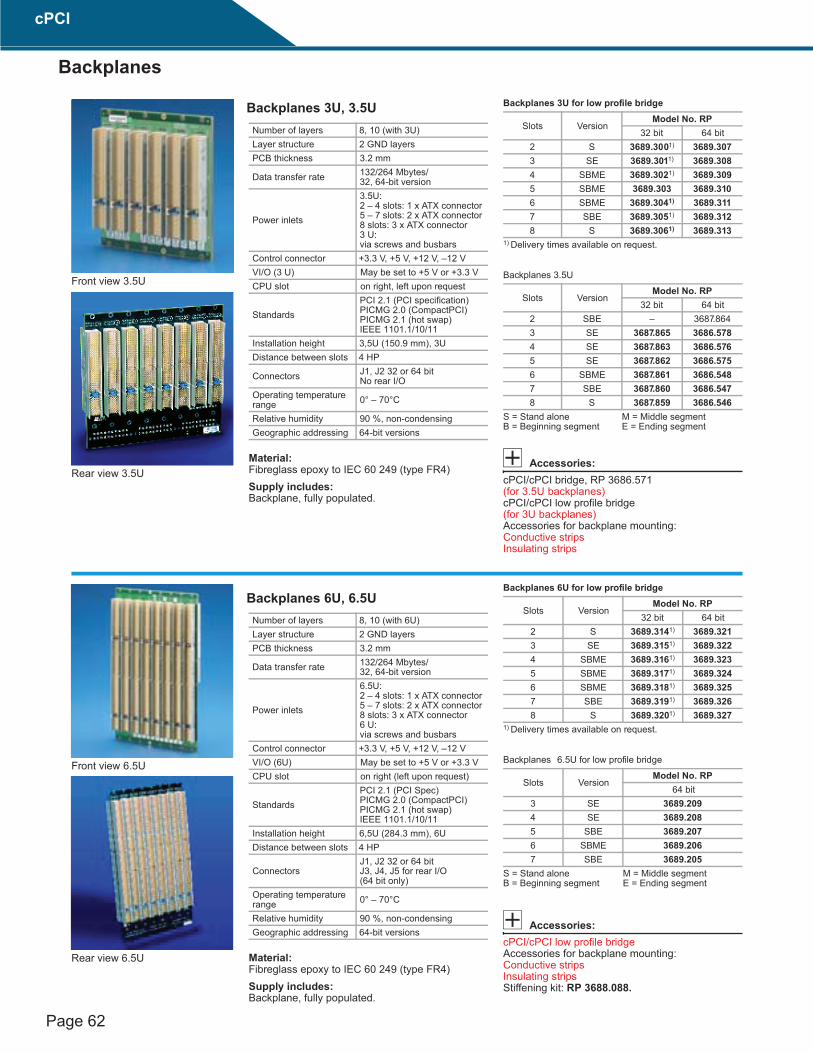
Material:Fibreglass epoxy to IEC 60 249 (type FR4)Supply includes:Backplane, fully populated.
Backplanes 3 U for low profile bridge
Backplanes 3.5 U
Accessories:cPCI/cPCI bridge, RP 3686.571 (for 3.5U backplanes) cPCI/cPCI low profile bridge (for 3U backplanes)Accessories for backplane mounting: Conductive stripsInsulating strips
Number of layers 8, 10 (with 3 U)Layer structure 2 GND layersPCB thickness 3.2 mm
Data transfer rate 132/264 Mbytes/32, 64-bit version
Power inlets
3.5 U:2 – 4 slots: 1 x ATX connector 5 – 7 slots: 2 x ATX connector 8 slots: 3 x ATX connector 3 U: via screws and busbars
Control connector +3.3 V, +5 V, +12 V, –12 VVI/O (3 U) May be set to +5 V or +3.3 VCPU slot on right, left upon request
StandardsPCI 2.1 (PCI specification) PICMG 2.0 (CompactPCI) PICMG 2.1 (hot swap) IEEE 1101.1/10/11
Installation height 3,5 U (150.9 mm), 3 U Distance between slots 4 HP
Connectors J1, J2 32 or 64 bit No rear I/O
Operating temperature range 0° – 70°C
Relative humidity 90 %, non-condensingGeographic addressing 64-bit versions
Front view 3.5U
Rear view 3.5U
Slots VersionModel No. RP
32 bit 64 bit2 S 3689.3001) 3689.3073 SE 3689.3011) 3689.3084 SBME 3689.3021) 3689.3095 SBME 3689.303 3689.3106 SBME 3689.3041) 3689.3117 SBE 3689.3051) 3689.3128 S 3689.3061) 3689.313
1) Delivery times available on request.
Slots VersionModel No. RP
32 bit 64 bit2 SBE – 3687.8643 SE 3687.865 3686.5784 SE 3687.863 3686.5765 SE 3687.862 3686.5756 SBME 3687.861 3686.5487 SBE 3687.860 3686.5478 S 3687.859 3686.546
S = Stand aloneB = Beginning segment
M = Middle segment E = Ending segment
Material:Fibreglass epoxy to IEC 60 249 (type FR4)Supply includes:Backplane, fully populated.
Backplanes 6 U for low profile bridge
Backplanes 6.5 U for low profile bridge
Accessories:cPCI/cPCI low profile bridge Accessories for backplane mounting: Conductive stripsInsulating strips Stiffening kit: RP 3688.088.
Number of layers 8, 10 (with 6 U)Layer structure 2 GND layersPCB thickness 3.2 mm
Data transfer rate 132/264 Mbytes/32, 64-bit version
Power inlets
6.5 U: 2 – 4 slots: 1 x ATX connector 5 – 7 slots: 2 x ATX connector 8 slots: 3 x ATX connector 6 U: via screws and busbars
Control connector +3.3 V, +5 V, +12 V, –12 VVI/O (6 U) May be set to +5 V or +3.3 VCPU slot on right (left upon request)
StandardsPCI 2.1 (PCI Spec) PICMG 2.0 (CompactPCI) PICMG 2.1 (hot swap) IEEE 1101.1/10/11
Installation height 6,5 U (284.3 mm), 6 U Distance between slots 4 HP
ConnectorsJ1, J2 32 or 64 bit J3, J4, J5 for rear I/O (64 bit only)
Operating temperature range 0° – 70°C
Relative humidity 90 %, non-condensingGeographic addressing 64-bit versions
Front view 6.5U
Rear view 6.5U
Slots VersionModel No. RP
32 bit 64 bit2 S 3689.3141) 3689.3213 SE 3689.3151) 3689.3224 SBME 3689.3161) 3689.3235 SBME 3689.3171) 3689.3246 SBME 3689.3181) 3689.3257 SBE 3689.3191) 3689.3268 S 3689.3201) 3689.327
1) Delivery times available on request.
Slots VersionModel No. RP
64 bit3 SE 3689.2094 SE 3689.2085 SBE 3689.2076 SBME 3689.2067 SBE 3689.205
S = Stand aloneB = Beginning segment
M = Middle segment E = Ending segment
cPCI
Backplanes
Backplanes 3U, 3.5U
Backplanes 6U, 6.5U
Material:Fibreglass epoxy to IEC 60 249 (type FR4) Supply includes:Backplane, fully populated.
Number of layers 10Layer structure 2 GND layersPCB thickness 3.2 mm
Data transfer rate 132/264 MBytes/32, 64-bit (for cPCI)
Power inletsup to 4 slots 1 x ATX connector 5 – 7 slots: 2 x ATX connector 8 slots: 3 x ATX connector
CPU slot Right
Standards
PCI 2.1 (PCI specification) PICMG 2.0 (CompactPCI) PICMG 2.1 (hot swap) PICMG 2.5 (cPCI Computer Telephony) IEEE 1101.1/10/11
Installation height 7 UDistance between slots 4 HP
ConnectorsJ1, J2 64 bit J3 rear I/O J4 H.110
Operating temperature range 0° – 70°C
Relative humidity 90 %, non-condensingGeographic addressing Yes
Front view
Rear view
H.110 connected to system slot
Slots cPCI version H.110 version Model No. RP3 SE SE 3688.5084 SE SBME 3688.5075 SE SBME 3687.8756 SBME SBME 3687.8747 SBE SBME 3687.8738 S SBME 3687.877
H.110 not connected to system slot
Slots cPCI version H.110 version Model No. RP3 S S 3688.4274 S SB 3688.4265 S SB 3688.5066 SB SB 3688.5057 SBE SB 3688.5048 S SB 9805.494
Extendible with low profile bridge.
S B M E
= Stand alone = Beginning segment = Middle segment = Ending segment
Key to J4 pin assignment CT_name = H.110 TDM bus signals+5 V = +5 V power+3.3 V = +3.3 V powerGND = logic groundV(I/O) = I/O cell powerFG = frame groundRSVD = reserved for future use
NP = a pin and pad REQUIRED to be not populated to meet safety regulations
IN/C = no connect required for safety agency insulation requirements
-SELVbat = short loop batterySELVbatRtn = short loop battery return-Vbat = telecom power distribution busVbatRtn = return bus pin for -VbatSGA0-SGA4 = shelf enumeration bus signalsGA0-GA4 = slot ID signals: not bussedVRG = bus for ringing voltageVRGRtn = bus for ringing voltagePFSO#-PFS1# = busses for power fail senseKEY AREA = area utilized for key
J4 pin assignment
No. Row Z Row A Row B Row C Row D Row E Row F25 NP SGA4 SGA3 SGA2 SGA1 SGA0 FG24 NP GA4 GA3 GA2 GA1 GA0 FG23 NP +12 V /CT reset /CT EN -12 V CT_MC FG22 NP PFSO# RSVD RSVD RSDV RSDV FG21 NP -SEL Vbat PFS1# RSDV RSDV SEL VbatRtn FG20 NP NP NP NP NP NP NP19 NP NP NP NP NP NP NP18 NP VRG IN/C IN/C IN/C VRGRtn NP17 NP NP NP NP NP NP NP16 NP NP NP NP NP NP NP15 NP -Vbat IN/C IN/C IN/C Vbat Rtn NP14
KEY AREA131211 NP CT_D29 CT_D30 CT_D31 V(I/O) /CT_FRAME GND10 NP CT_D27 +3.3 V CT_D28 +5 V /C_FRAME B GND9 NP CT_D24 CT_D25 CT_D26 GND /FR_COMP GND8 NP CT_D21 CT_D22 CT_D23 +5 V CT_C8 A GND7 NP CT_D19 +5 V CT_D20 GND CT_C8 B GND6 NP CT_D16 CT_D17 CT_D18 GND CT_NETREF GND5 NP CT_D13 CT_D14 CT_D15 +3.3 V CT_NETREF GND4 NP CT_D11 +5 V CT_D12 +3.3 V SCLK GND3 NP CT_D8 CT_D9 CT_D10 GND SCLK-D GND2 NP CT_D4 CT_D5 CT_D6 CT_D7 GND GND1 NP CT_D0 +3.3 V CT_D1 CT_D2 CT_D3 GND

Page 63
Material:Fibreglass epoxy to IEC 60 249 (type FR4)Supply includes:Backplane, fully populated.
Backplanes 3 U for low profile bridge
Backplanes 3.5 U
Accessories:cPCI/cPCI bridge, RP 3686.571 (for 3.5U backplanes) cPCI/cPCI low profile bridge (for 3U backplanes)Accessories for backplane mounting: Conductive stripsInsulating strips
Number of layers 8, 10 (with 3 U)Layer structure 2 GND layersPCB thickness 3.2 mm
Data transfer rate 132/264 Mbytes/32, 64-bit version
Power inlets
3.5 U:2 – 4 slots: 1 x ATX connector 5 – 7 slots: 2 x ATX connector 8 slots: 3 x ATX connector 3 U: via screws and busbars
Control connector +3.3 V, +5 V, +12 V, –12 VVI/O (3 U) May be set to +5 V or +3.3 VCPU slot on right, left upon request
StandardsPCI 2.1 (PCI specification) PICMG 2.0 (CompactPCI) PICMG 2.1 (hot swap) IEEE 1101.1/10/11
Installation height 3,5 U (150.9 mm), 3 U Distance between slots 4 HP
Connectors J1, J2 32 or 64 bit No rear I/O
Operating temperature range 0° – 70°C
Relative humidity 90 %, non-condensingGeographic addressing 64-bit versions
Front view 3.5U
Rear view 3.5U
Slots VersionModel No. RP
32 bit 64 bit2 S 3689.3001) 3689.3073 SE 3689.3011) 3689.3084 SBME 3689.3021) 3689.3095 SBME 3689.303 3689.3106 SBME 3689.3041) 3689.3117 SBE 3689.3051) 3689.3128 S 3689.3061) 3689.313
1) Delivery times available on request.
Slots VersionModel No. RP
32 bit 64 bit2 SBE – 3687.8643 SE 3687.865 3686.5784 SE 3687.863 3686.5765 SE 3687.862 3686.5756 SBME 3687.861 3686.5487 SBE 3687.860 3686.5478 S 3687.859 3686.546
S = Stand aloneB = Beginning segment
M = Middle segment E = Ending segment
Material:Fibreglass epoxy to IEC 60 249 (type FR4)Supply includes:Backplane, fully populated.
Backplanes 6 U for low profile bridge
Backplanes 6.5 U for low profile bridge
Accessories:cPCI/cPCI low profile bridge Accessories for backplane mounting: Conductive stripsInsulating strips Stiffening kit: RP 3688.088.
Number of layers 8, 10 (with 6 U)Layer structure 2 GND layersPCB thickness 3.2 mm
Data transfer rate 132/264 Mbytes/32, 64-bit version
Power inlets
6.5 U: 2 – 4 slots: 1 x ATX connector 5 – 7 slots: 2 x ATX connector 8 slots: 3 x ATX connector 6 U: via screws and busbars
Control connector +3.3 V, +5 V, +12 V, –12 VVI/O (6 U) May be set to +5 V or +3.3 VCPU slot on right (left upon request)
StandardsPCI 2.1 (PCI Spec) PICMG 2.0 (CompactPCI) PICMG 2.1 (hot swap) IEEE 1101.1/10/11
Installation height 6,5 U (284.3 mm), 6 U Distance between slots 4 HP
ConnectorsJ1, J2 32 or 64 bit J3, J4, J5 for rear I/O (64 bit only)
Operating temperature range 0° – 70°C
Relative humidity 90 %, non-condensingGeographic addressing 64-bit versions
Front view 6.5U
Rear view 6.5U
Slots VersionModel No. RP
32 bit 64 bit2 S 3689.3141) 3689.3213 SE 3689.3151) 3689.3224 SBME 3689.3161) 3689.3235 SBME 3689.3171) 3689.3246 SBME 3689.3181) 3689.3257 SBE 3689.3191) 3689.3268 S 3689.3201) 3689.327
1) Delivery times available on request.
Slots VersionModel No. RP
64 bit3 SE 3689.2094 SE 3689.2085 SBE 3689.2076 SBME 3689.2067 SBE 3689.205
S = Stand aloneB = Beginning segment
M = Middle segment E = Ending segment
Material:Fibreglass epoxy to IEC 60 249 (type FR4) Supply includes:Backplane, fully populated.
Number of layers 10Layer structure 2 GND layersPCB thickness 3.2 mm
Data transfer rate 132/264 MBytes/32, 64-bit (for cPCI)
Power inletsup to 4 slots 1 x ATX connector 5 – 7 slots: 2 x ATX connector 8 slots: 3 x ATX connector
CPU slot Right
Standards
PCI 2.1 (PCI specification) PICMG 2.0 (CompactPCI) PICMG 2.1 (hot swap) PICMG 2.5 (cPCI Computer Telephony) IEEE 1101.1/10/11
Installation height 7 UDistance between slots 4 HP
ConnectorsJ1, J2 64 bit J3 rear I/O J4 H.110
Operating temperature range 0° – 70°C
Relative humidity 90 %, non-condensingGeographic addressing Yes
Front view
Rear view
H.110 connected to system slot
Slots cPCI version H.110 version Model No. RP3 SE SE 3688.5084 SE SBME 3688.5075 SE SBME 3687.8756 SBME SBME 3687.8747 SBE SBME 3687.8738 S SBME 3687.877
H.110 not connected to system slot
Slots cPCI version H.110 version Model No. RP3 S S 3688.4274 S SB 3688.4265 S SB 3688.5066 SB SB 3688.5057 SBE SB 3688.5048 S SB 9805.494
Extendible with low profile bridge.
S B M E
= Stand alone = Beginning segment = Middle segment = Ending segment
Key to J4 pin assignment CT_name = H.110 TDM bus signals+5 V = +5 V power+3.3 V = +3.3 V powerGND = logic groundV(I/O) = I/O cell powerFG = frame groundRSVD = reserved for future use
NP = a pin and pad REQUIRED to be not populated to meet safety regulations
IN/C = no connect required for safety agency insulation requirements
-SELVbat = short loop batterySELVbatRtn = short loop battery return-Vbat = telecom power distribution busVbatRtn = return bus pin for -VbatSGA0-SGA4 = shelf enumeration bus signalsGA0-GA4 = slot ID signals: not bussedVRG = bus for ringing voltageVRGRtn = bus for ringing voltagePFSO#-PFS1# = busses for power fail senseKEY AREA = area utilized for key
J4 pin assignment
No. Row Z Row A Row B Row C Row D Row E Row F25 NP SGA4 SGA3 SGA2 SGA1 SGA0 FG24 NP GA4 GA3 GA2 GA1 GA0 FG23 NP +12 V /CT reset /CT EN -12 V CT_MC FG22 NP PFSO# RSVD RSVD RSDV RSDV FG21 NP -SEL Vbat PFS1# RSDV RSDV SEL VbatRtn FG20 NP NP NP NP NP NP NP19 NP NP NP NP NP NP NP18 NP VRG IN/C IN/C IN/C VRGRtn NP17 NP NP NP NP NP NP NP16 NP NP NP NP NP NP NP15 NP -Vbat IN/C IN/C IN/C Vbat Rtn NP14
KEY AREA131211 NP CT_D29 CT_D30 CT_D31 V(I/O) /CT_FRAME GND10 NP CT_D27 +3.3 V CT_D28 +5 V /C_FRAME B GND9 NP CT_D24 CT_D25 CT_D26 GND /FR_COMP GND8 NP CT_D21 CT_D22 CT_D23 +5 V CT_C8 A GND7 NP CT_D19 +5 V CT_D20 GND CT_C8 B GND6 NP CT_D16 CT_D17 CT_D18 GND CT_NETREF GND5 NP CT_D13 CT_D14 CT_D15 +3.3 V CT_NETREF GND4 NP CT_D11 +5 V CT_D12 +3.3 V SCLK GND3 NP CT_D8 CT_D9 CT_D10 GND SCLK-D GND2 NP CT_D4 CT_D5 CT_D6 CT_D7 GND GND1 NP CT_D0 +3.3 V CT_D1 CT_D2 CT_D3 GND
cPCI
Backplanes
Backplanes 7U with H.110

Page 64
The “Switch Fabric” backplanes comply with PICMG specification 2.16. They support telephony applications and a high le vel of system availability in which cPCI is combined with Ethernet for high-speed applications.
Material:Fibreglass epoxy to IEC 60 249 (type FR4)Supply includes:Backplane, fully populated.
Technical specifications: ● 7U, 84 HP/32 HP● Comply with PICMG 2.1,
fully hot swap-compatible● Selectable voltage V (I/O) (3.3 V or 5 V) where
configured for 33 MHz CompactPCI ● Integral Schottky diode bus terminator● Prepared for up to four backplane reinforce-
ments to avoid bending during card insertion● H.110 CT bus complies with specification
PICMG 2.5 at all node slots ● Support 8 HP CPU boards when one node slot
is relinquished● Twin redundant support for Switch Fabric
(2 fabric and 12 basic nodes), as specified in PICMG 2.16
● Support rear transition modules with all board slots
● Configurable for power supply with either two 6U x 8 HP, three 6U x 4 HP, three 3U x 4 HP, three 3U x 8 HP or four 3 U x 4 HP
● All power supply slots conform to PICMG 2.11● Power supply connectors for H.110-Vbat,
-SELVbat and VRG power signals● ATX power connector for auxiliary power inlet/
outlet● Two fan power connectors for 12 V and system
management support● System control bus (SMBus) complies with
PICMG 2.9 and supports all boards, power supplies, power entry modules, fans and alarm cards
● Support of I2C bridge function on the alarm card for >19 SMBus nodes
Power inlets Positronic 47-pole, or ATXCPU slot Right
Standards
PCI 2.1 (PCI specification) PICMG 2.0 (CompactPCI) PICMG 2.1 (hot swap) PICMG 2.5 (cPCI Computer Telephony) IEEE 1101.1/10/11 PICMG 2.16
Installation height7 U (6 U for RP 3686.396 and RP 3689.186)
Distance between slots 4 HPOperating temperature range 0° – 70°C
Relative humidity 90 %, non-condensingGeographic addressing Yes
Width Number of slots Description of slots Model No. RP
32 HP 8
1 Fabric slot 6 node slots with cPCI and H.110 1 host slot
3689.188
see RP 3689.188, but without H.110 3686.414
64 HP 16
1 Fabric slot 6 node slots with cPCI and H.110 1 host slot 1 Fabric slot6 node slots with cPCI and H.110 1 host slot 3 slots for power supplies
3686.396
see RP 3686.396, but without H.110 3689.186
84 HP 21
7 node slots with cPCI and H.110 1 host slot 1 node slot with H.110 without cPCI 1 Fabric slot7 node slots with cPCI and H.110 1 host slot 1 node slot with H.110 without cPCI 1 Fabric slot1 Alarm slot
3686.397
see RP 3686.397, but without H.110 3689.190see RP 3686.397, but without cPCI 3689.191
Front Rear 1 System (CPU) card 12 Node card2 Node card 13 Node card3 Node card 14 Node card4 Node card 15 Node card5 Node card 16 Fabric card B6 Node card 17 Blank7 Node card 18 Power supply 18 Fabric card A 19 Power supply 29 System (CPU) card 20 Power supply 310 Node card 21 Blank11 Node card
1 System RTC 12 Node RTC2 Node RTC 13 Node RTC3 Node RTC 14 Node RTC4 Node RTC 15 Node RTC5 Node RTC 16 Fabric B RTC6 Node RTC 17 Alarm card7 Node RTC 18
PEM 18 Fabric A RTC 199 System RTC 20
PEM 210 Node RTC 2111 Node RTC
cPCI
Backplanes
Backplanes 7U, Switch Fabric to PICMG 2.16

Page 65
cPCI bridge may be connected to the rear to extend the bus by a maximum of 7 additional slots. The cPCI bridge handles all communica-tions between the individual bus segments. The front slots are freely available for cPCI boards. It supports the 64-bit PCI bus and may be used in conjunction with cPCI backplanes 3.5 U and 6.5U.Technical specifications:● May be connected to the rear of cPCI back-
planes● PCI bridge● 64 bit “high performance” Intel 21 154● For use with Pixus cPCI backplanes
(not with low profile backplanes)● Corresponding to PCI specifications 2.1● Conforms to cPCI ● cPCI bridge connects cPCI backplanes from
right to left (as viewed from the front) – i.e. the “left-hand” connector accommodates the host board
Material:Fibreglass epoxy to IEC 60 249 (FR4)Supply includes:Bridge, fully populated.
Front viewRear view
1
2
suB ICPC yradnoceSsuB ICPC yramirP
PCI BusArbitrition
PCI BusClock
PCI BusGeneral
PCI BusArbitrition
PCI BusClocks
PCI BusGeneral
PCI-PCIBridge
Intel 21 154
///
/
/
1 7
/7
/
/
7
1
1
tib-46tib-46
1
2
Description Model No. RP64-bit cPCI bridge 3686.571
Extended delivery times.
cPCI bridge may be connected to the rear to extend the bus by a maximum of 7 additional slots, without any loss of slots: Optionally availableas a 32-bit or 64-bit ve rsion. Only suitable for use in conjunction with low profile backplanes.Material:Fibreglass epoxy to IEC 60 249 (FR4)Supply includes:Bridge, fully populated.
32-bit version64-bit version
1
2
1
2
Version Bit Model No. RPleft-right 32 3689.210right-left 32 3689.211left-right 64 9810.637right-left 64 9812.625right-left 64 3687.8801)
1) For backplane H.110
cPCI
Backplanes
Modular cPCI bridge
Modular low profile bridge

Page 66
● Board 3U /3.5U (0.5U may be broken off), 8HP, 16H, 24 HP
● For use in conjunction with cPCI backplanes
●
Accommodation of 1/2/3 power supplies with up to 250 W
●
AC/DC connection is made via two 3-pole connectors
●●
Complies with PICMG 2.0, PICMG 2.11Technical specifications:Accommodation of 1/2/3 cPCI power supplies with up to 250 W.The second power supply unit may be used for redundancy (with power distribution) or, via parallel connection, to increase the current.
Input voltages:
●AC input via 2 x 3-pole AMP Mate-N-Lock (AMP # 350732-1), connector J12
●Connected via pin 45, 46, 47, type Positronic
●Maximum current load per pin is 25 A, matching counter-connector for cable harness AMP # 350715
●DC input via 2 x 3-pole AMP Mate-N-Lock (AMP # 350732-1), connector J5 connected via pin 46, 47, type Positronic
●Maximum current load per pin is 25 A, matching counter-connector for cable harness AMP # 350715 Output voltage:
●Three 20-pole ATX-compatible connectors for ATX cable harness (connection of power supply board to cPCI backplane)
Material:Fibreglass epoxy to IEC 60 249 (FR4)Supply includes:Board, fully populated.Note:Plug-in power supplies
Description HP Model No. RP3U for 1 x plug-in power supply with Positronic connector, 47-pin
8 9905.105
3U board for 3 x plug-in power supplies with Positronic connector, 47-pin
24 9904.131
3.5 U board for 2 x plug-in power supplies with Positronic connector, 47-pin
16 3688.603
ATX (12˝) cable harness 9810.337ATX (16˝) cable harness 3686.570ATX (20˝) cable harness 9810.338
Posit
roni
c PC
147F
300
A1
Posit
roni
c PC
1477
F300
A1
ATX
Con
nect
orAT
X C
onne
ctor
ATX
Con
nect
or
Mat
e-n-
Lok
(DC
-Inpu
t Pow
er)
Mat
e-n-
Lok
(AC
-Inpu
t Pow
er)
Sens
eH
eade
r
Con
trol
Hea
der
3.5
HE 3
HE
16 TE
RP 3688.603
Outgoing voltages to supply one or more cPCI backplanes are available at ATX-compatible connectors
cPCI
Backplanes
Power supply board 3U/3/5U

Page 67
Board 6U/6.5U (0.5U may be broken off), 8 HP
●
● For use in conjunction with cPCI back-planes 3.5U, 6.5U, H.110
● Accommodation of a power supply of up to 500 W
● AC/DC connection is made via 3-pole connec-tors
● Outgoing voltages to supply one or more cPCI backplanes are availabl e at 3 ATX-compatible connectors or at special power terminals
● Complies with PICMG 2.0, PICMG 2.11Technical specifications:Accommodation of a 6U cPCI power supply with up to 500 W.Input voltages:● AC input via 3-pole AMP Mate-N-Lock
connector Max. current capacity per pin 25 A
● DC input via 3-pole AMP Mate-N-Lock connector Max. current capacity per pin 25 A
Output voltage:● Three 20-pole ATX-compatible connectors for
ATX cable harness (connection of power supply board to cPCI backplane) and/or special power terminals
Material:Fibreglass epoxy to IEC 60 249 (FR4)Supply includes:Board, fully populated. Note:Plug-in power supplies
ATX
Con
nect
orAT
X C
onne
ctor
ATX
Con
nect
or
6 H
E
6.5
HE
GND
+5 V
+5 V
GND
+12 V
+12 V
GND
GND
+3 V
Loca
lS
ense
Posi
troni
c P
CI4
7F30
0A1
Mat
e-n-
Lock
(Inpu
t Pow
er)
Con
trol H
eade
r ( X )
17.2
7
12
34
45
46
47
20 19
44 43 42
26 25 2423 22 21
RP 3688.607
Description Model No. RP1 x plug-in power supply with Positronic connector, 47-pin
3688.607
ATX (12˝) cable harness 9810.337ATX (16˝) cable harness 3686.570ATX (20˝) cable harness 9810.338
Extended delivery times.
cPCI
BackplanesPower supply board6U/6.5U, 8HP

Page 68
● Board 6U /6.5U (0.5U may be broken off), 16HP
● For use in conjunction with Pixus cPCI back-planes
● Accommodation of two power supplies with up to 500 W
● AC/DC connection is made via two 2 x 3-pole connectors
● Outgoing voltages to supply one or more cPCI backplanes are availabl e at 5 ATX-compatible connectors or at special power terminals
● Complies with PICMG 2.0, PICMG 2.11 Technical specifications:Accommodation of 2 x 6U cPCI power supplies of up to 500 WInput voltages:● AC input via 2 x 3-pole AMP Mate-N-Lock
connector Max. current capacity per pin 25 A
● DC input via 2 x 3-pole AMP Mate-N-Lock connector Max. current capacity per pin 25 A
Output voltage:● Five 20-pole ATX-compatible connectors for
ATX cable harness (connection of power supply board to cPCI backplane) and/or special power terminals
Material:Fibreglass epoxy to IEC 60 249 (FR4)Supply includes:Board, fully populated.Note:Plug-in power supplies
17.2
7
( X )
Backplane Top Edge
12
34
45
46
47
20 19
44 43 42
26 25 2423 22 21
ATX Connector
ATX Connector
ATX Connector
ATX
Con
nect
or
ATX Connector
48 VOUT
48 VRTN
GND
+5 V +5 V +5 V +5 V +5 V
+3 V +3 V +3 V +3 V +3 V
+12 V +12 V +12 V +12 V +12 V
GND GND GND GND GND
GND GND GND GND GND
Loca
l Sen
seH
eade
r
Posi
troni
c P
CI4
7F30
0A1
Posi
troni
c P
CI4
7F30
0A1
Mat
e-n-
Lock
(Inpu
t Pow
er)
Con
trol H
eade
r
6 H
E
6.5
HE
RP 3688.608
Description Model No. RPBoard for 2 x plug-in power supplies with Positronic connector, 47-pin
3688.608
ATX (12˝) cable harness 9810.337ATX (16˝) cable harness 3686.570ATX (20˝) cable harness 9810.338
Extended delivery times.
cPCI
Power supply boards
Power supply board6U/6.5U, 16HP
Page 69
● Board 6U /6.5U (0.5U may be broken off), 16HP
● For use in conjunction with Pixus cPCI back-planes
● Accommodation of two power supplies with up to 500 W
● AC/DC connection is made via two 2 x 3-pole connectors
● Outgoing voltages to supply one or more cPCI backplanes are availabl e at 5 ATX-compatible connectors or at special power terminals
● Complies with PICMG 2.0, PICMG 2.11 Technical specifications:Accommodation of 2 x 6U cPCI power supplies of up to 500 WInput voltages:● AC input via 2 x 3-pole AMP Mate-N-Lock
connector Max. current capacity per pin 25 A
● DC input via 2 x 3-pole AMP Mate-N-Lock connector Max. current capacity per pin 25 A
Output voltage:● Five 20-pole ATX-compatible connectors for
ATX cable harness (connection of power supply board to cPCI backplane) and/or special power terminals
Material:Fibreglass epoxy to IEC 60 249 (FR4)Supply includes:Board, fully populated.Note:Plug-in power supplies
17.2
7
( X )
Backplane Top Edge
12
34
45
46
47
20 19
44 43 42
26 25 2423 22 21
ATX Connector
ATX Connector
ATX Connector
ATX
Con
nect
or
ATX Connector
48 VOUT
48 VRTN
GND
+5 V +5 V +5 V +5 V +5 V
+3 V +3 V +3 V +3 V +3 V
+12 V +12 V +12 V +12 V +12 V
GND GND GND GND GND
GND GND GND GND GND
Loca
l Sen
seH
eade
r
Posi
troni
c P
CI4
7F30
0A1
Posi
troni
c P
CI4
7F30
0A1
Mat
e-n-
Lock
(Inpu
t Pow
er)
Con
trol H
eade
r
6 H
E
6.5
HE
RP 3688.608
Description Model No. RPBoard for 2 x plug-in power supplies with Positronic connector, 47-pin
3688.608
ATX (12˝) cable harness 9810.337ATX (16˝) cable harness 3686.570ATX (20˝) cable harness 9810.338
Extended delivery times.
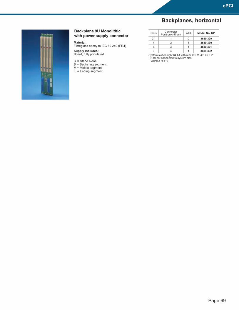
Material:Fibreglass epoxy to IEC 60 249 (FR4) Supply includes:Board, fully populated.
S = Stand alone B = Beginning segment M = Middle segment E = Ending segment
Slots Connector Positronic 47-pin ATX Model No. RP
21) 1 0 3689.3294 2 1 3689.3306 3 1 3689.3318 4 1 3689.332
System slot on right 64 bit with rear I/O, V I/O: +5.0 V. H.110 not connected to system slot.1) Without H.110
cPCI
Backplanes, horizontal
Backplane 9U Monolithicwith power supply connector


