Backpack Sprayer - GEMPLER'S - Outdoor Work … · Manual No. 181702 Rev F. 02/02/12 ECN11-023 5...
12
Manual No. 181702 Rev F. 02/02/12 ECN11-023 5 1/2” x 8 1/2” Booklet Do Not Return This Backpack To The Store For Help, Information or Parts, Call : 1-800-311-9903 The Fountainhead Group, Inc. 23 Garden St., New York Mills, NY 13417 1-800-311-9903 www.TheFountainheadGroup.com CAUTION: Read and follow all instructions BACKPACK SPRAYER Backpack Sprayer Use and Care Manual
Transcript of Backpack Sprayer - GEMPLER'S - Outdoor Work … · Manual No. 181702 Rev F. 02/02/12 ECN11-023 5...
Manual No. 181702Rev F. 02/02/12
ECN11-0235 1/2” x 8 1/2” Booklet
Do Not Return This Backpack To The StoreFor Help, Information or Parts, Call : 1-800-311-9903
The Fountainhead Group, Inc.23 Garden St., New York Mills, NY 13417
1-800-311-9903www.TheFountainheadGroup.com
CAUTION: Read and follow all instructions
BACKPACKSPRAYER
Backpack SprayerUse and Care Manual
Page 1
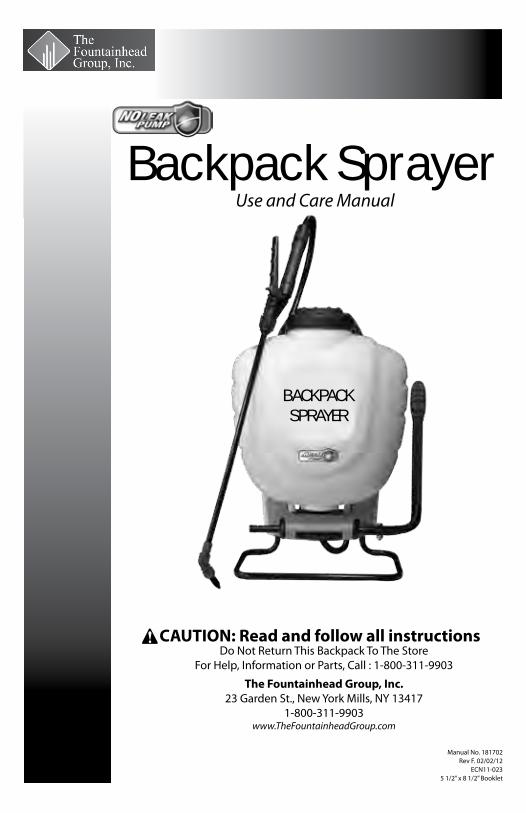
Do not return sprayer to store, if you experience problems or have questions contact our toll free Customer Service Center, M-F 8AM - 5PM, EST, at 1-800-311-9903, ore-mail: [email protected], or access online at: www.TheFountainheadGroup.com.
SAFETY PRECAUTIONS• Read owner’s manual completely before operating this sprayer.• Always use goggles, gloves, and protective clothing when using sprayer.• Read and follow all instructions and cautions on label of products used in this sprayer.• Never use flammable liquids, caustics, acids, or hot water in this tank.• Do not leave sprayer in the sun when not in use.• Spray when air is calm to prevent drift of chemicals.• Do not use sprayer near open flame or anything that could cause ignition of the spray.• Always inspect hose and all hose connections before each use. A damaged hose, or loose hose connection can result in unintended exposure to the pressurized chemical, resulting in serious injury or property damage.• Do not lift or carry sprayer by the hose, shut-off valve, or wand extension. Carry by the handle only.• Do not pressurize with any mechanical device such as an air compressor, since this can create a dangerous pressure level and bursting of parts resulting in serious injury. Only use original pump.• Do not store chemicals in this tank.• Always release pressure when sprayer is not in use and before performing any maintenance.• Clean and rinse sprayer thoroughly after each use.• Never attempt to alter sprayer from original condition.• Always use replacement parts from original manufacturer.• Keep the sprayer and all chemicals out of the reach of children.
WARNINGThe sprayer is operated with liquid under pressure. Failure to observe caution and to follow instructions for operating and cleaning can cause tank, hose and other parts to be weakened and rupture under pressure. This can result in serious injury from high pressure discharge of liquids or forcible ejection of parts. Do not use flammable materials in this sprayer. Material could ignite or explode, causing serious injury and/orpossible death. For safe use of this product, you must read and follow all instructions before use.
TEST SPRAYER WITH WATER BEFORE USING ANY CHEMICALS.
CAUTIONAlways empty, clean and dry tank, pump system, shut-off, hose, and extension after each use. FAILURE TO DO SO MAY WEAKEN SPRAYER COMPONENTS, CAUSING COMPONENTS TO RUPTURE WHEN PRESSURIZED. Additionally, FAILURE TO CLEAN AND PROPERLY MAINTAIN YOUR SPRAYER WILL VOID MANUFACTURER’S WARRANTY.
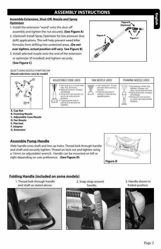
ASSEMBLY INSTRUCTIONS
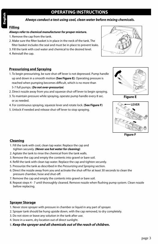
Assemble Pump HandleSlide handle onto shaft and line up holes. Thread bolt through handle and shaft and securely tighten. Thread on lock nut and tighten using a 13mm (or adjustable) wrench. Handle can be mounted on left or right depending on user preference. (See Figure D)
FOAMING NOZZLE USES:FAN NOZZLE USES:ADJUSTABLE CONE USES:
Spot spraying in flower beds, walkways, driveways, and patios, around trees and shrubs.Edging along fences, driveways and walkways.Killing brush such as poison ivy, poison oak, kudzu and wild blackberry.
Lawn replacement. Kill lawn and weeds before planting a new lawn.Preparing large areas for planting of ornamental and vegetable gardens.
Spot spraying in or around flower beds, trees, and shrubs.Edging along fences, driveways, and walkways.Killing brush such as poison ivy, poison oak, kudzu and wild blackberry.Preparing garden beds for planting of ornamentals and vegetables.
SELECT USING NOZZLE CHART BELOW(Nozzle selections vary by model)
A. Cap NutB. Foaming NozzleC. Adjustable Cone NozzleD. Fan NozzleE. Flat SealF. AdapterG. Extension
Assemble Extension, Shut-Off, Nozzle and Spray Optimizer1. Install the extension “wand” onto the shut-off assembly and tighten the nut securely. (See Figure A)2. (Optional) Install Spray Optimizer for low pressure (low drift) applications. This will help prevent weed killer formulas from drifting into undesired areas. (Do not over tighten, actual position will vary. See Figure B)3. Install selected nozzle onto the end of the extension or optimizer (if installed) and tighten securely. (See Figure C)
Figure A
Figure B(Optional)
Figure C
Figure D
Folding Handle (included on some models)1. Thread bolt through handle
and shaft as stated above.2. Snap strap around
handle.3. Handle shown in
folded position.
Page 2
A
B E
DC
F
G
Pressurizing and Spraying1. To begin pressurizing, be sure shut-off lever is not depressed. Pump handle up and down in a smooth motion (See Figure E). Operating pressure is reached when pumping becomes difficult, which is no more than 5-7 full pumps. (Do not over-pressurize)2. Direct nozzle away from you and squeeze shut-off lever to begin spraying.3. To maintain pressure while spraying, operate pump handle every 8 sec. or as needed.4. For continuous spraying, squeeze lever and rotate lock. (See Figure F)5. Unlock if needed and release shut-off lever to stop spraying.
page 3
Cleaning1. Fill the tank with cool, clean tap water. Replace the cap and tighten securely. (Never use hot water for cleaning)2. Agitate the tank to rinse the chemical from the tank walls.3. Remove the cap and empty the contents into gravel or bare soil.4. Refill the tank with clean tap water. Replace the cap and tighten securely.5. Pressurize the tank as described in the Pressurizing and Spraying section.6. Direct the nozzle away from you and activate the shut-off for at least 30 seconds to clean the pressure chamber, hose and shut-off.7. Remove the cap and empty the contents into gravel or bare soil.8. Repeat steps 4 - 7 until thoroughly cleaned. Remove nozzle when flushing pump system. Clean nozzle before replacing.
Always conduct a test using cool, clean water before mixing chemicals.
OPERATING INSTRUCTIONS
FillingAlways refer to chemical manufacturer for proper mixture.1. Remove the cap from the tank.2. Make sure the filter basket is in place in the neck of the tank. The filter basket includes the seal and must be in place to prevent leaks.3. Fill the tank with cool water and chemical to the desired level. 4. Reinstall the cap.
Figure E
Figure F
Sprayer Storage1. Never store sprayer with pressure in chamber or liquid in any part of sprayer.2. Sprayer tank should be hung upside down, with the cap removed, to dry completely.3. Do not store or leave any solution in the tank after use.4. Store in a warm, dry location out of direct sunlight.
5. Keep the sprayer and all chemicals out of the reach of children.
LEVER

Always conduct a test using cool, clean water before mixing chemicals.
Page 4
MAINTENANCE
Tank Maintenance1. After each use, rinse the tank with cool, clean water.2. Check the check valve (See Figure G) and filter basket gasket. (See Figure H) Make sure they do not show signs of wear and are operating properly. Replace them as required.3. Clean any dirt or debris from the filter basket.4. Periodically check the straps for fraying. Replace them as required.
Figure G Figure H
Pressure Chamber MaintenanceWARNING: Always depressurize sprayer before cleaning or replacing pressure chamber by activating shut-off and spraying out all pressure.1. Remove the tank cap and strainer (See Figure I).2. Reach into the tank and turn the chamber 1/4 turn counterclockwise (See Figure J) to unlock the chamber from the pump then remove chamber from tank (See Figure K). 3. Rinse out any debris that may have accumulated in the chamber.4. Reinstall the chamber into the pump by aligning the tabs on the chamber with the slots in the pump, push firmly into pump and turn clockwise until pump stops.5. Reinstall the strainer and tank cap (See Figure L).
Included with some models:
High Capacity Pressure Chamber (for longer spray duration)6. Using figures I2 - L2 as a reference, follow steps 1 - 5 in Pressure Chamber Maintenance section above.
Figure L
Figure I
Figure K
Figure J
Clockwise
Counter-Clockwise
A B
C
A. HandleB. FilterC. Shut-off Assembly
Shut-off Maintenance (Smith Pro)Always depressurize sprayer before maintenance by activating shut-off and spraying contents out.1. Unscrew the handle from the shut-off assembly.2. Remove the filter from the shut-off assembly.3. Clean any debris from inside the handle, shut-off assembly, or the filter by rinsing with cool, clean water.4. Reassemble the components as shown and tighten all connections securely.
A B
C
Nozzle Maintenance1. If nozzle clogs, remove and disassemble the nozzle assembly.2. Clean the openings of any obstructions and reassemble.
Figure L2
Figure I2
Figure K2
Figure J2
Clockwise
Counter-Clockwise

page 5
SERVICING INSTRUCTIONS
Tank Servicing Steps1. Unscrew cap from tank. Remove and replace check valve. (See Figure 1)2. Remove pressure chamber as outlined in Pressure Chamber Maintenance section of the manual. Remove and replace o-ring. Lubricate o-ring with petroleum jelly. (See Figure 2) 3. Unsnap agitator from piston rod. Remove from tank. (See Figure 3)
Figure 3Figure 2Figure 1
4. Position pump handle to the furthest downward position. Remove pump handle from sprayer. (See Figure 4)5. Disassemble carry handle by removing the (6) screws. (See Figure 5)6. Remove hitch pin and lift pivot clip off of the piston rod. (See Figure 6)
Figure 6Figure 4 Figure 5
Prior to servicing and/or repairs.1. Empty contents of tank.2. While squeezing shut-off, pump sprayer until all liquid is expelled.3. Continue squeezing shut-off without pumping to release all air pressure.4. You will find all parts for servicing primary seals and gaskets to be included in KIT #24.

SERVICING INSTRUCTIONS CON’T
7. Pull upward to slide piston rod out of pump. (See Figure 7)8. While holding onto the pump, use an adjustable wrench to unthread pump nut from pump. Remove nut, hose and barb assembly. (See Figure 8)9. Inspect (2) o-rings on barb assembly. If damaged, replace hose assembly. (See Figure 9)
Figure 9Figure 8Figure 7
page 6
Figure 10 Figure 11 Figure 12
10. Remove pump out of tank. Remove and replace gasket. (See Figure 10)11. Slide piston rod assembly down and out of grommet and remove from tank. (See Figure 11)12. Carefully remove and replace o-ring from piston. Lubricate o-ring with petroleum jelly. (See Figure 12)
Figure 13 Figure 14 Figure 15
13. Remove grommet from tank using pliers to grasp the head of the grommet while flexing the grommet out of the hole in the tank. Press or tap new grommet into tank. Lubricate hole in grommet with petroleum jelly. (See Figure 13)14. Insert piston rod assembly into tank and through grommet. (See Figure 14)15. Reassemble pump with gasket into tank. (See Figure 15) for correct orientation. Tighten pump nut securely with adjustable wrench while holding pump to maintain correct orientation. Push piston assembly into pump.

SERVICING INSTRUCTIONS CON’T
page 7
16. Attach pivot clip to piston rod and insert hitch pin. Note orientation of piston rod must match the pivot clip. (See Figure 16)17. Reassemble carry handle onto tank. Tighten all (6) screws. (See Figure 5)18. To reinstall the agitator, line the notch up on the agitator with the swedge on piston rod and snap into place. (See Figure 17)19. Reinstall pressure chamber as outlined in the Pressure Chamber Maintenance section. (See Figure 18)
Figure 16 Figure 17 Figure 18
Harness Installation 1. For each side, remove the small plastic clips from the two shoulder strap loops and thread each loop through the slots at the top of the carry handle. Replace the clips through the loops and pull strap securing the two shoulder straps in place. (See Figure 20)
2. To install lower end of the straps, remove strap from top portion of buckles and place around the foot stand, starting from underneath. (See Figure 21)
3. Loop strap through the first section of buckle. (See Figure 22)
4. Next loop strap through other section of buckle and tighten (See Figure 23). Adjust the shoulder pads and strap length for a comfortable fit.
Figure 23Figure 22
Figure 21Figure 20
Figure 19
20. Replace tank cap, filter (See FIgure 19) and pump handle (See Figure 4).
page 8
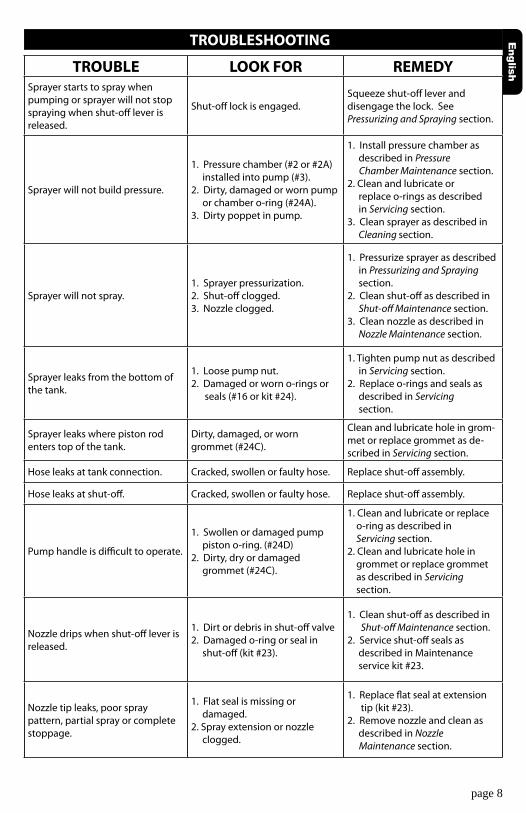
TROUBLESHOOTING
TROUBLE LOOK FOR REMEDYSprayer starts to spray when pumping or sprayer will not stop spraying when shut-off lever is released.
Shut-off lock is engaged.Squeeze shut-off lever and disengage the lock. SeePressurizing and Spraying section.
Sprayer will not build pressure.
1. Pressure chamber (#2 or #2A) installed into pump (#3). 2. Dirty, damaged or worn pump or chamber o-ring (#24A). 3. Dirty poppet in pump.
1. Install pressure chamber as described in Pressure Chamber Maintenance section. 2. Clean and lubricate or replace o-rings as described in Servicing section. 3. Clean sprayer as described in Cleaning section.
Sprayer will not spray.1. Sprayer pressurization. 2. Shut-off clogged. 3. Nozzle clogged.
1. Pressurize sprayer as described in Pressurizing and Spraying section. 2. Clean shut-off as described in Shut-off Maintenance section. 3. Clean nozzle as described in Nozzle Maintenance section.
Sprayer leaks from the bottom of the tank.
1. Loose pump nut. 2. Damaged or worn o-rings or seals (#16 or kit #24).
1. Tighten pump nut as described in Servicing section. 2. Replace o-rings and seals as described in Servicing section.
Sprayer leaks where piston rod enters top of the tank.
Dirty, damaged, or worn grommet (#24C).
Clean and lubricate hole in grom-met or replace grommet as de-scribed in Servicing section.
Hose leaks at tank connection. Cracked, swollen or faulty hose. Replace shut-off assembly.
Hose leaks at shut-off. Cracked, swollen or faulty hose. Replace shut-off assembly.
Pump handle is difficult to operate.
1. Swollen or damaged pump piston o-ring. (#24D) 2. Dirty, dry or damaged grommet (#24C).
1. Clean and lubricate or replace o-ring as described in Servicing section. 2. Clean and lubricate hole in grommet or replace grommet as described in Servicing section.
Nozzle drips when shut-off lever is released.
1. Dirt or debris in shut-off valve2. Damaged o-ring or seal in shut-off (kit #23).
1. Clean shut-off as described in Shut-off Maintenance section. 2. Service shut-off seals as described in Maintenance service kit #23.
Nozzle tip leaks, poor spraypattern, partial spray or complete stoppage.
1. Flat seal is missing or damaged. 2. Spray extension or nozzle clogged.
1. Replace flat seal at extension tip (kit #23). 2. Remove nozzle and clean as described in Nozzle Maintenance section.
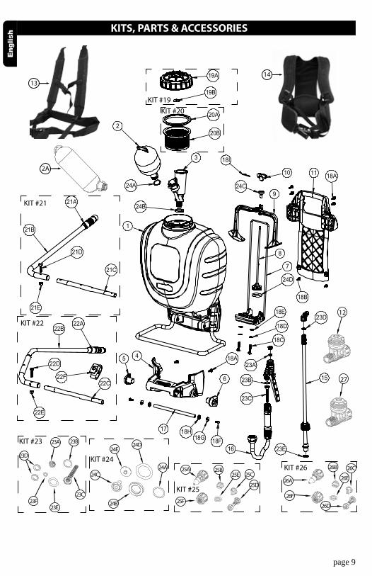
KITS, PARTS & ACCESSORIES
page 9
1
24B
2
3
20A
20B
19A
19B
18I
24C
10
8
7
9
24D
11
18D
23A
15
18F18G18H
6
17
22C22F
21B
21D
5 4
21C
18A
18A
18B
22D
21E
22E
18C
18E
23B
23C
24A
23D
22B
23E
22A
21A
1623A
1314
23B
23C
23D
23E23F
24E24D
24C
24B
24A
26F
26E
26D
26C26B
26A
25F
25E
25D
25C25B25A
12
27
KIT #19KIT #20
KIT #21
KIT #23
KIT #26
KIT #25
KIT #24
KIT #22
2A
page 10
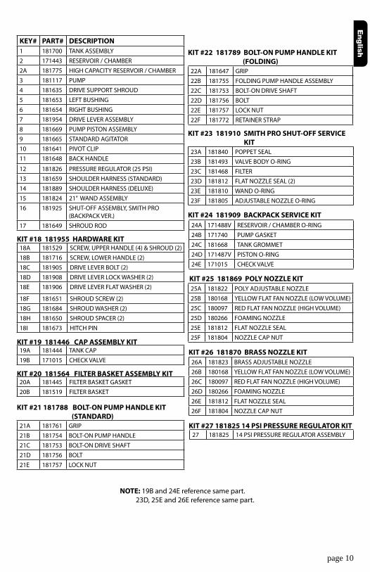
KEY# PART# DESCRIPTION1 181700 TANK ASSEMBLY2 171443 RESERVOIR / CHAMBER2A 181775 HIGH CAPACITY RESERVOIR / CHAMBER3 181117 PUMP4 181635 DRIVE SUPPORT SHROUD5 181653 LEFT BUSHING6 181654 RIGHT BUSHING7 181954 DRIVE LEVER ASSEMBLY8 181669 PUMP PISTON ASSEMBLY9 181665 STANDARD AGITATOR10 181641 PIVOT CLIP11 181648 BACK HANDLE
12 181826 PRESSURE REGULATOR (25 PSI)13 181659 SHOULDER HARNESS (STANDARD)14 181889 SHOULDER HARNESS (DELUXE)15 181824 21” WAND ASSEMBLY 16 181925 SHUT-OFF ASSEMBLY, SMITH PRO
(BACKPACK VER.)17 181649 SHROUD ROD
KIT #21 181788 BOLT-ON PUMP HANDLE KIT (STANDARD)21A 181761 GRIP21B 181754 BOLT-ON PUMP HANDLE21C 181753 BOLT-ON DRIVE SHAFT21D 181756 BOLT21E 181757 LOCK NUT
20A 181445 FILTER BASKET GASKET20B 181519 FILTER BASKET
KIT #20 181564 FILTER BASKET ASSEMBLY KIT
19A 181444 TANK CAP19B 171015 CHECK VALVE
KIT #19 181446 CAP ASSEMBLY KIT
18A 181529 SCREW, UPPER HANDLE (4) & SHROUD (2)18B 181716 SCREW, LOWER HANDLE (2)18C 181905 DRIVE LEVER BOLT (2)18D 181908 DRIVE LEVER LOCK WASHER (2)18E 181906 DRIVE LEVER FLAT WASHER (2)
18F 181651 SHROUD SCREW (2)18G 181684 SHROUD WASHER (2)18H 181650 SHROUD SPACER (2)18I 181673 HITCH PIN
KIT #18 181955 HARDWARE KIT
22A 181647 GRIP22B 181755 FOLDING PUMP HANDLE ASSEMBLY22C 181753 BOLT-ON DRIVE SHAFT22D 181756 BOLT22E 181757 LOCK NUT22F 181772 RETAINER STRAP
KIT #22 181789 BOLT-ON PUMP HANDLE KIT (FOLDING)
KIT #23 181910 SMITH PRO SHUT-OFF SERVICE KIT23A 181840 POPPET SEAL23B 181493 VALVE BODY O-RING23C 181468 FILTER23D 181812 FLAT NOZZLE SEAL (2)23E 181810 WAND O-RING23F 181805 ADJUSTABLE NOZZLE O-RING
KIT #24 181909 BACKPACK SERVICE KIT24A 171488V RESERVOIR / CHAMBER O-RING24B 171740 PUMP GASKET24C 181668 TANK GROMMET24D 171487V PISTON O-RING24E 171015 CHECK VALVE
KIT #25 181869 POLY NOZZLE KIT25A 181822 POLY ADJUSTABLE NOZZLE25B 180168 YELLOW FLAT FAN NOZZLE (LOW VOLUME)25C 180097 RED FLAT FAN NOZZLE (HIGH VOLUME)25D 180266 FOAMING NOZZLE25E 181812 FLAT NOZZLE SEAL25F 181804 NOZZLE CAP NUT
KIT #26 181870 BRASS NOZZLE KIT26A 181823 BRASS ADJUSTABLE NOZZLE26B 180168 YELLOW FLAT FAN NOZZLE (LOW VOLUME)26C 180097 RED FLAT FAN NOZZLE (HIGH VOLUME)26D 180266 FOAMING NOZZLE26E 181812 FLAT NOZZLE SEAL26F 181804 NOZZLE CAP NUT
KIT #27 181825 14 PSI PRESSURE REGULATOR KIT27 181825 14 PSI PRESSURE REGULATOR ASSEMBLY
NOTE: 19B and 24E reference same part. 23D, 25E and 26E reference same part.

SERVICE KITS, PARTS & ACCESSORIES ARE AVAILABLE BY CONTACTINGThe Fountainhead Group, Inc. - Customer Service Center
Monday - Friday 8 a.m. - 5 p.m., ESTToll Free: 1-800-311-9903
ore-mail: [email protected]
orAccess online at: www.TheFountainheadGroup.com
page 11