BACKGROUND STUDIES IN SUPPORT OF A …/67531/metadc621449/m2/1/high... · Kundig and W. S. Lyman,...
244
Received by OSff AUG 0 7 1990 UCRL-~21082 OE90 015107 BACKGROUND STUDIES IN SUPPORT OF A FEASIBILITY ASSESSMENT ON THE USE OF COPPER-BASE MATERIALS FOR NUCLEAR WASTE PACKAGES IN A REPOSITORY IN TUFF Introduction by R. A. Van Konynenburg Appendices by K. J . A. Kundig, W. S. Lyman, M. Prager, 3. R. Meyers, and I . S . Servi (Copper Development Association, Inc. and International Copper Research Association, Inc.) Manuscript Date; Publication Date: May 1988 June 1990
Transcript of BACKGROUND STUDIES IN SUPPORT OF A …/67531/metadc621449/m2/1/high... · Kundig and W. S. Lyman,...

Received by OSff AUG 0 7 1990
UCRL-~21082
OE90 015107
BACKGROUND STUDIES IN SUPPORT OF A FEASIBILITY ASSESSMENT ON THE USE OF COPPER-BASE
MATERIALS FOR NUCLEAR WASTE PACKAGES IN A REPOSITORY IN TUFF
Introduction by R. A. Van Konynenburg
Appendices by K. J . A. Kundig, W. S. Lyman, M. Prager,
3. R. Meyers, and I . S. Servi (Copper Development Association, Inc. and
International Copper Research Association, Inc . )
Manuscript Date; Publication Date:
May 1988 June 1990

DISCLAIMER
This document was prepared as an account of work sponsored by an agency of the United States Government. Neither the United States Government nor the University of California nor any of their employees, makes any warranty, express or implied, or assumes any legal liability or responsibility for the accuracy, completeness, or usefulness of any information, apparatus, product, or process disclosed, or represents that its use would not infringe privately owned rights. Reference herein to any specific commercial products, process, or service by trade name, trademark, manufacturer, or otherwise, does not necessarily constitute or imply its endorsement, recommendation, or favoring by the United States Government or the University of California, The views and opinions of authors expressed herein do not necessarily state or reflect those of the United States Government or the University of California, and shall not be used for advertising or product endorsement purposes.
Prepared by Yucca Mountain Project (YMP) participants as part of the Civilian Radioactive Waste Management Program. The Yucca Mountain Project is managed by the Waste Management Project Office of the U.S. Department of Energy, Nevada Operations Office. Yucca Mountain Project work is sponsored by the DOE Office of Civilian Radioactive Waste Management.
'Work performed under the auspices of the U.S. Department of Energy by Lawrence Livermore National Laboratory under Contract W-7405-ENG-48.

BACKGROUND STUDIES IN SUPPORT OF A FEASIBILITY ASSESSMENT ON THE USE OF COPPER-BASE MATERIALS FOR NUCLEAR WASTE
PACKAGES IN A REPOSITORY IN TUFF
Abstract
This report combines six work units performed in FY'85-86 by the Copper Development Association and the International Copper Research Association under contract with the University of California. The work includes literature surveys and state-of-the-art summaries on several considerations influencing the feasibility of the use of copper-base materials for fabricating high-level nuclear waste packages For the proposed repository in tuff rock at Yucca Mountain, Nevada. The general conclusion from this work was that copper-base materials are viable candidates for inclusion in the materials selection process for this application.

BACKGROUND STUDIES IN SUPPORT OF A FEASIBILITY ASSESSMENT ON THE USE OF COPPER-BASE MATERIALS FOR NUCLEAR WASTE
PACKAGES IN A REPOSITORY IN TUFF
Pursuant to the provisions of the Nuclear Waste Policy Act of 1982, as 2 amended in 1987, the U. S. Department of Energy (DOE) is engaged in the development of a high level nuclear waste repository through its Office of Civilian Radioactive Waste Management (OCRWM). At the time of writing (May, 1988) the List of candidate sites under consideration for the repository has been reduced to one; namely, Yucca Mountain, located in southern Nevada.
The Yucca Mountain site is being explored by the Nevada Nuclear Waste Storage Investigations (NNWSI) Project, administered by the Waste Management Project Office (WMPO) of the Nevada Operations Office (NVOD) of the DDE. Within this project, several organizations and laboratories are responsible for particular aspects. Among them, Lawrence Livermore National Laboratory (LLNL) has the responsibility for designing, testing, and projecting the long-term performance of the waste packages for the Yucca Mountain site. One aspect of this effort is the selection and testing of the material to be used for fabricating the waste packages.
Early in the project, NNWSI selected the iron to nickel-based austenitic materials as the candidate alloy system. Then, in 1984, in response to a directive from the Congress and the President, OOE instructed NNWSI to evaluate the feasibility of using copper-based materials for the waste packages, and to provide input for a report to the Congress at the end of FY'86. The now-defunct Basalt Waste Isolation Project (BWIP), which was studying an alternate repository site on the Hanford reservation in Washington, was instructed to do likewise.
LLNL developed an appropriate test plan to carry out the work, and it was reviewed by WMPO and OCRWM and finalized in December, 1984. In formulating this test plan, LLNL received considerable help from the Copper Development Association, Inc. (COA) and International Copper Research Association, Inc. (INCRA).
- 2 -

Several individual work units were carried out under this plan during FY'85 and FY'86, and a workshop was held on March 13-14, 1986, in Houston, Texas, to discuss progress up to that time and to exchange information with waste package researchers from Sweden and Canada as well as BWIP.
Reports 3 , 4 were written at the ends of FY'85 and FY'86, respectively, summarizing the NNWSI work, and DOE submitted a report to the Congress indicating that copper-based materials appeared to be feasible candidates for waste package construction. At the present time, there are six candidate waste package materials under consideration, namely types 3Q4L and 316L stainless steel, alloy 825 (a high-nickel austenitic alloy), and three copper-based materials (CDA 102, CDA 613 and CDA 715). We are also considering alternative metals and ceramics. We intend to reduce this field to one alloy and one alternative at the end of FY'89, and then to carry out comprehensive testing subsequently.
In the course of this feasibility investigation we have received several written reports from our CDA and INCRA contract researchers as well as from others on various aspects of the work. Although some of this work has since been extended or the conclusions somewhat modified by new information, we believe it i:; desirable to release these reports for publication at this time, so that all interested parties may examine the work that led to the positive feasibility assessment. Readers are advised that these reports represent the "best effort" that could be marshalled in the time available for this short feasibility assessment. SOTO questions remain and are being pursued. In cases where subsequent work has modified individual conclusions, we have so indicated in short summaries of each report. The reports being grouped together here are of the nature of literature or state-of-the-art summaries. They have been combined because of the close relationship of their subject matter and to promote efficiency in the publication process. All the work in this report was carried out under contract with CDA and INCRA.
- 3 -

The reports included in this package of work are the following, and arc attached as numbered appendices:
1. K. J. A. Kundig and W. S. Lyman, "Report of Meeting - Workshop/Seminar on Copper-Base Waste Package Container Materials," March 13-14, 1986, Copper Development Association, Inc. Greenwich, CT.
2. K. J. A. Kundig, "Fabrication Alternatives for Manufacturing Copper and Copper Alloy Nuclear Waste Containers - A Survey of Manufacturing Options," Copper Development Association, Inc., Greenwich, CT (May 30, 1986).
3. M. Prager, "Implications of Alloy Variables for Candidate Materials for Copper and Copper Alloy Nuclear Waste Containers," Copper Development Association, Inc. Greenwich, CT (June 2, 1986).
4. J. R. Meyers, "Corrosion and Oxidation of Copper and Selected Copper Alloys in Air, Steam, and Water at Temperatures up to 300°C," Copper Development Association, Inc., Greenwich, CT (July 18, 1986).
5. W. S. Lyman and I. S. Servi, "Copper Availability and Cost Considerations - A Survey of Published Forecasts to the Year 2000," Copper Development Association, Inc., Greenwich, CT (June 23, 1986).
6. Copper Development Association, Inc., and International Capper Research Association, Inc., "Properties of Copper and Copper Alloys Under Consideration for Nuclear Waste Containers," Copper Devel. Ass'n., Inc., Greenwich, CT (June 23, 1986).
Three other reports, covering experimental work, are being published separately.
- 4 -

The six included reports will be discussed in order.
1. Workshop/Seminar on Copper-Based Materials (Kundig and Lyman) The purpose of this meeting was to provide a forum for exchange of
information among researchers involved in studying the use of copper and its alloys for high level nuclear waste containers. Although no formal conclusions were reached, it was generally agreed that the workshop had served its purpose well. A few comments are in order to provide consistency with the current situation, and to point out items of particular interest:
a. The 1987 amendments to the Nuclear Waste Policy Act have eliminated consideration of basalt, salt, and crystalline rock as host rocks for the repository in the U. S. The only site currently under consideration is the tuff site at Yucca Mountain, Nevada.
b. The current plan in the U. S. is not to reprocess commercial waste, so 4 that the maximum gamma dose rates are expected to be in the 10 rad per hour
range, near spent fuel containers, rather than 2x10 rad per hour from commercial high level waste.
c. More detailed heat transfer calculations now indicate that a significant fraction of the waste container surfaces will drop below the boiling point of water before the end of the 3Q0- to 1000-year containment period, so that liquid water films will be present on some containers during this period.
d. Some of the information from other programs is applicable to the NNWSI effort, while other data are not directly relevant. The reducing redox conditions, water saturation, and hydrostatic head result in very different environments for the waste packages in the other programs. However, the information about fabrication of copper containers by HIPping and by electron beam welding of roll-and-weld structures in Sweden (Mattsson) is interesting. Also the availability of creep data for some of the copper alloys (Cohen) is
- 5 -

of interest to us. The absence of stress corrosion cracking in copper for nitrite levels less than 69 mg/i (Mattsson) is significant. The data on copper corrosion in boiler feedwater (Myers) is useful. The information on fabricability (Kundig) is very helpful.
2. Fabrication Alternatives (Kundig) The purpose of this report was to survey the possible ways of
manufacturing copper-based waste containers. Conclusions of the study were as follows:
"Waste canisters of both the NNWSI and BWIP suggested designs can be made relatively simply utilizing currently available technology. Some development work is needed: automatic welding, particularly £B welding for closure seams, must be tailored to the materials and configurations chosen; extrusion of canister-size, one-end-closed vessels must be worked out if extrusion is chosen as a manufacturing option; process parameters for the HIPping of copper and copper alloys must be optimized; and materials handling technology must be developed to perform loading and encapsulation under hot cell conditions. Research and development work of this nature will be needed no matter what the choice of canister material, and it can therefore be concluded that the use of copper-base metals is in no way limiting to the manufacture of practical, sound waste containers."
The following comments are made with respect to this report:
a. Electron-beam welding is termed the "reference welding method." This selection was made only for the purpose of Kundig's report. Currently, NNWSI is considering several closure processes and has not yet settled upon a reference method.
- 6 -

b. The President has determined that commercial and defense high level waste will be emplaced in the same repository.
c. A Quality Assurance Program Plan has been developed since this report was written, and appropriate quality control and assurance provisions will i*. applied to fabrication of the containers.
d. This report appears to be a good summary of the state-of-the-art. 8 9
NNWSI is continuing to explore methods of fabrication and closure and to compare them on the basis of several desirable characteristics, with the objective of selecting the best methods for this application. 3. Alloy Variables (Prager)
This report discusses the effects of variations in copper alloy composition on properties important in the waste package application. Although no specific conclusions were reached, it contains a large amount of detailed information that will be particularly useful in writing an alloy specification, if a copper-based material is selected for the waste packages.
4. Corrosion and Oxidation (Meyers) This report reviews the literature on corrosion and oxidation of the
pertinent copper-based materials under conditions relevant to the repository environment. No conclusions are presented. This work is being amplified and extended to include more recent work in the degradation mode surveys currently
... 10 in preparation.
5. Availability and Cost, (Lyman and Servi) This report reviews the copper resource picture worldwide, discusses
historical trends in supply and demand as well as price, and discusses projections for the future. The following conclusions are reached:
a. All forecasters project some growth but relatively weak demand for the balance of the 1980's, and growing demand leading to a somewhat firmer market for copper in the 1990's.
- ? -

b. Overcapacity of supply will continue to prevail into the 1990's. Whenever indications of a potential shortfall in supply become evident, expansion projects now in the planning stage will be activated promptly and the supply-demand balance will be maintained.
c. All substantial expansions of copper supply will occur outside North America, and a substantial fraction will occur in Chile, which will become increasingly dominant among the world producers of primary copper.
d. Because U. S. costs of production are higher than those abroad (especially in Chile), the U.S.A., which has until recently imported only some ten percent of its copper needs, is likely to become somewhat more dependent on foreign sources.
e. In the U.S.A., an increasing fraction of copper demand will be satisfied by old scrap, which is abundantly available from domestic sources.
f. Overall, there is no concern about the availability of copper in the U.S.A., barring unpredictable emergencies.
g. The price of refined copper will rise gradually in the 1990's from the current range around 65 cents per pound, but will never exceed 90. cents per pound by the year 2000, expressed in 1985 dollars.
Although the projections in this report extend only to the year 2000, whereas the need for waste containers will extend beyond this time, the information presented clearly shows that the availability and cost of copper are sufficiently predictable to justify consideration of copper-based materials as candidates. The cost estimate given per container could be reduced perhaps as much as 25% by purchase of production volumes of starting material.
*This projection was based on data up to 1985. There have been recent price increases, and readers should be aware that price forecasting is not an exact science.

6. Properties (CDA and INCRA) This report presents a Ubeful summary cf the pertinent physical and
mechanical properties of the candidate copper-based materials. It concludes that attention should be focused more closely on mechanical properties needed for the specific waste package application. It should be noted that the 90-10 copper-nickel alloy was a candidate for the now-defunct BWIP project, not for the NNWSI Yucca Mountain repository project. The phosphorous-deoxidized copper (C12200) has essentially the same copper content as the oxygen-free copper (010200), i.e., essentially pure copper, but offers some protection
* against oxidation during welding, and is thus considered for our purposes as a variant of the oxygen-free copper candidate.
It should also be noted that the NNWSI project has not made a decision to * require that waste packages be subject to the A5ME Boiler and Pressure Vessel
Code. When detailed specifications are written they may or may not include provisions of the code.
- 9 -

Conclusions from the Work Reported On the basis of thp work reported herein as well as some experimental work
reported elsewhere, " we concluded that copper-base materials are appropriate for inclusion as candidates in the on-going materials selection process for Yucca Mountain waste packages. As noted earlier, we intend to narrow the current list of candidates to one by the end of FY'69.
-10 -

References
1. Nuclear Waste Policy Act of 1982, 42 U.S.C. 10101, Congressional Record-House, pp. H-10525 to H-10544, (December 20,1982). (NNA.870608.0095)
2. Nuclear Waste Policy Amendments Act of 1987, House of Representatives Report 100-495, Omnibus Budget Reconciliation Act of 1987, (December 21, 1987). (NNA.870916.0042)
* 3. R. D. McCright, "FY'85 Status Report on Feasibility Assessment of Copper-Base Waste Package Container Materials in a Tuff Repository," UCID-20509, Lawrence Livermore National Laboratory, Livermore, CA (September 30, 1985). (HQS.880517.2492)
4. C. F. Acton and R. D. McCright, "Feasibility Assessment of Copper-Base Waste Package Container Materials in a Tuff Repository," UCID-20847, Lawrence Livermore National Laboratory, Livermore, CA (September 30, 1985). (HQS.880517.2376)
5. M. Akkaya and E. D. Verink, Jr., Foreword by R. A. Van Konynenburg "Electrochemical Corrosion Studies on Copper-Base Waste Package Container Materials in Unirradiated 0.1 N NaN03 at 95°C," available as Lawrence Livermore National Laboratory, Livermore, CA, UCID-21076, (May 1988). (NNA.891101.0040)
6. H. D. Smith, "An Experimental Investigation of Copper-Zircaloy Interactions Under Potential Tuff Repository Conditions," WHC-EP-0173, UC-70 Westinghouse Hanford Company, Richland, WA (February, 1987) available as Lawrence Livermore National Laboratory Report UCRL-21115, (September 1988). (NNA.891213.0189)
-11-

7. W. H. Yunker, "Corrosion Behavior of Copper-Base Materials in a Gamma-Irradiated Environment: Final Report," to be published by Westing house Hanford Company, Richland, WA, (WHC-EP-0188), available as Lawrence Livermore National Laboratory UCRL-21118, in review.
8. K. 0. Stein, H. A. Domain, R. L. Holbrook, and D. F. LaCount, "Fabrication Development for High-Level Nuclear Waste Containers for the Tuff Repository - Phase 1 Final Report," prepared by Babcock and Wilcox under subcontract by Lawrence LivermoreNational Laboratory (BAW-2010) also available as Lawrence Livermore National Laboratory report UCRL-15965, in review.
9. K. 0. Stein, E. S. Robitz, Jr., M. D. McAninch, and D. P. Edmonds, "Closure Development for High-Level Nuclear Waste Containers for the Tuff Repository - Phase 1 Final Report, prepared by Babcock and Wilcox under subcontract by Lawrence Livermore National Laboratory (BAW-2009), in review.
10. G. E. Gdowski and D. B. Bullen, "Survey of Degradation Modes of Candidate Materials for High-Level Radioactive-Waste Disposal Containers, Volume 2, Oxidation and Corrosion," UriD-21362, August 1938). (NNA.891222.0307)
-12-

REPORT OF MEETING
Workshop/Seminar on
Copper-Base Waste Package Container Materials
March 13-14,1986
Adam's Mark Hotel - Houston, Texas
written for
Lawrence Livermore National Laboratory and Rockwell Hanford Operations
by
Konrad J.A. Kundig and W. Stuart Lyman CDA/INCRA Joint Advisory Group
University of California Purchase Order 637805
Copper Development Association Inc. Greenwich Office Park 2, Box 1840
Greenwich, CT 06836

DISCLAIMER
This document was prepared as an account of work sponsored cyan agency of the United Stales Government, Neither ihc United States Government nor the University of California nor any of their employees, makes any warranty, express or implied, or assumes any legal liability or responsibility (or the accuracy, completeness, or usefulness of any information, apparatus, product, or process disclosed, or represents that its use would nol infringe privately owned rights. Reference herein to aiw specific commercial products, process, or service by trade name, trademark, manulacturcr. or otherwise, docs noi necessarily constitute or imply us endorsement, recommendation, or favoring by the United Slates Government orthe University of California, 'file views anil opinions of authors expressed herein do not nccessanly state or reflect those of the United Slates Government or the University of California, and shall not lie used far advertising or product endorsement purposes.
Prepared by Nevada Nuclear Waste Storage Investigations (NNWSI) Project participants as part of the Civilian Radioactive Waste Management Program, The NNWSI Project is managed by the Waste Management Project Office of the U.S. Department of Energy, Nevada Operations Office. NNWSI Project work is sponsored by the Office of Geologic Repositories of the DOE Office of Civilian Radioactive Waste Management.
Wort performed under the auspices of the U.S. Department of Energy by Lawrence Uvermorc National Laboratory under Contract W-i-IUS-lxg-W.

TABLE OF CONTENTS
Page
PREFACE i
BACKGROUND AND PURPOSE OF MEETING 1
SYNOPSIS OF TECHNICAL PRESENTATIONS 2 Disposal Environments and their Implications for Copper 2
1. Basalt (BWIP/RHO-T.B, McCall, R.P. Anantatmula) 2 2. Crystalline Rock
2.1 (SKB-E. Mattsson) 7 2.2 (AECL/WNRE-F.King) 10 2.3 (OCRD-A.A. Bauer) 13
3.Tuff(NNWSI/LLNL-R.A.VanKonynenburg) 13 Corrosion
1. Previous Work/Current Knowledge 1.1 (CDA/INCRA-J.R. Myers) 18 1.2 (SKB-E. Mattsson) 23
2. On-going Experimental Results 2.1 (AECL/WNRE- F. King) 26 2.2 (BWIP/RHO-R.P. Anantatmula) 28 2.3 (NNWSI/LLNL - R.D. McCright, R.S. Glass,
W.H.Smyrl, H.D. Smith, W. Yunker) 32 2.4 (SKB - E. Mattsson) 42
3. Thermodynamics (CDA/INCRA-E.D.Verink) 42 Mechanical Properties, Design, and Fabrication
1. Available Property Data (CDA/INCRA-A. Cohen) 46 2. Design and Fabrication Approaches
2.1 (SKB- L. Werme) 46 2.2 (NNWSI/LLNL-R.D.McCright) 47 2.3 (BWIP/RHO-J.CKrogness) 49 2.4 (AECL/WNRE-F. King) 50
3. Fabrication Alternatives - U. S. Capabilities and Facilities (CDA/INCRA-KJ.A. Kundig) 52
Future plans and Needs 1. R.D. McCright (NNWSI/LLNL) 57 2. R.P. Anantatmula (BWIP/RHO) 57 3. A.A. Bauer (OCRD) 57 4. F.KJng(AECLAVNRE) 57 5. L. Werme (SKB) 58
ADJOURNMENT 58
APPENDIX A-AGENDA I APPENDIX B-ATTENDANCE IV

J PREEACE
On March 13 and 14, 1986, a workshop/seminar on copper-base nuclear waste nackage container materials was held in Houston, Texas, The purpose of the meeting was to provide a forum for the interchange of technical data, information, and ideas on the use of copper and its alloys for the container application.
The workshop was part of the U.S. Departmentof Energy (DOE) proyram established in 19X4 devaluate the leasibility of copper as a potential waste package container material in repository media other than salt. Investigations of copper for thispurpose began in fiscal year 1985 within the programs of the Nevada Nuclear Waste Storage Investigation (NNWSI) and the Basalt Waste Isolation Project (BWIP). In that connection, Lawrence Livermore National Laboratory (LLNL) called on the U.S. copper and brass industry, via a contract with Copper Development Association Inc. (CDA), to provide technical support and advice on the properties and application of copper and copper alloys to both its own NNWSI proyram and to BWIP,s program, spearheaded by Rockwell Hanford Operations (RHO). A joint advisory group of specialists was set up by CDA and the International Copper Research Association. Inc, (JNCRA) to help carry out these copper industry responsibilities to the DOE program.
In addition to the copper investigation of NNWSI and BWIP, copper is also being studied as a container material by the Swedish Nuclear Fuel and Waste Management Co. (SKB) and by Atomic Energy of Canada Limited (AECLj, focussed at the Whiteshell Nuclear Research Establishment (WNRE/. DOE has also established a copper evaluation responsibility for the second U.S. repository program in the Office of Crystalline Repository Development (OCRD).
It *as deemed timely in early 1985 to bring together the key copper investigators in ihe.se several programs for an informa1 but intensive technical exchange of data, experiences, ideas and plans in order that the individual programs might efficiently benefit from their complementary efforts and to guard against unnecessary duplication of effort. Organization and running of the workshop/seminar was undertaken as part of the copper industry support effort under the contract with CDA. The seminar agenda appears as Appendix A.
Individuals from other appropriate organizations were also invited to participate in the workshop. These included copper subcontractors of organizations mentioned above the U.S. Nuclear Regulatory Commission and its subcontractors, two other National Laboratories, specialists from the U.S. copper industry, and independent consultants. Thirty-six people attended, representing twenty different organizations and three independent consultants. They are listed in Appendix B.
This report completes the workshop/seminar task. It is intended to provide a useful summary reference record of the fourteen hours of presentations and discussion by the seventeen presenters and nineteen other participants, including a small selection of the many charts and tables which they used.
This report on the workshop was originally prepared so that the information was available for preparing the NNWSI and BWIP feasibility reports on copper as a waste package container material (September 1 %(>). The workshop report is now being issued by NNWSI for more general distribution as part of the information base that NNWSI plans to use to support the container material selection for advanced design work. During the FY-I985 and 1986 feasibility evaluation of copper, NNWSI and BWIP agreed to share certain resources. Part of that agreement was NNWSI's sponsorship of aspects of the evaluation involving CDA's participation, including organization of the workshop.

Since the time that the draft of this report was first prepared and is now generally issued, some organizational changes have occurred that affect the affiliations of some of the workshop participants. Also, overall schedule changes involving the container material selection and design milestones have occurred. We have not attempted to update these changes, so that the workshop report accurately reflects the procedings of the March 1986 workshop.
Workshop/Seminar on Copper-Base Waste Package Container Materials
BACKGROUND AND PURPOSE OF THE MEETING
The Nuclear Waste Policy Act of 1982 mandates that civilian reactor spent fuel and other forms of high-level waste be disposed of by burial in geologic repositories, Potential sites for the first repository include Yucca Mountain, on the western edge of the Nevada Test Site about 80 miles northwest of Las Vegas; the Hanford Reservation near Richland, in eastern Washington; andsites inTexas, Utah and Mississippi. Potential sites for the second repository will also include crystalline rock environments in the eastern U.S.
The waste container material must be compatible with the repository environment. Since the gcohydrol-ogy differs from site to site, this implies that the choice of container material will be site-specific, with perhaps a different material having optimum corrosion resistance for each site. Thus, researchers for the Nevada site selected one "reference" material, those for Hanford another, and so forth.
Copper and its alloys are distinguished by their intrinsic corrosion resistance, a property for which they have been exploited for millennia. It was primarily for this reason that in 1984 the Department of Energy asked the Nevada Nuclear Waste Storage Investigation Project (NNWSI) and the Basalt Waste Isolation Project (BWIP) to include copper and copper alloys in their material appraisal programs during FY 1985 and 1986 and to report to the Congress by September, 1986 on the suitability of these materials for waste packages. At that time, according to R. D. McCright of the Lawrence Livermore National Laboratory, who opened the workshop, the respective DOE project offices asked the Copper Development Association Inc. (CDA) and the International Copper Research Association (INCRA) to use their extensive information and data base, their broad technical experience, and their network of technical associates and contacts to provide assistance in the selection and study of appropriate copper-base materials. Dr. McCright noted that not only were the copptir metals' corrosion and oxidation resistance to be considered, but also their compatibility with the several waste forms, their availability and economics, their mechanical properties, and their ability to be fabricated into container configurations using contemporary technology.
Dr. McCright noted that the workshop was organized to provide a technology-transfer forum to share information among those working on copper metals for high level waste containers in waste repository environments. Participants invited to make informal presentations of their work included representatives from the Lawrence Livermore National Laboratory, which conducts research for the Yucca Mountain site under the NNWSI; Rockwell Hanford Organization (RHO), which directs research for the Hanford site under BWIP; and the Battelle Project Management Division, which administers and conducts as-yet preliminary investigations for the siting of a second U.S. repository in granite for the Office of Crystalline Rock Repository Development (OCRD). Battelle is also the prime contractor for a proposed repository in salt dome formations. Since copper metals are probably not appropriate for use in this environment, salt repository programs were not included in the workshop. Technical presentations on the Canadian and Swedish disposal programs were included, however, since both these countries are actively working on the use of copper for their own waste containers.
1

SYNOPSES OF TECHNICAL PRESENTATIONS
Disposal Environments and Their Implications for Copper-Base Materials
The waste package chosen for each repository environment must provide for the "substantially complete" containment of radionuclides for between 300 and 1000 years. For the subsequent 10,000 years, releases from the repository are limited to one part in 105 per year of the lOOOth-year inventory of radionuclides. The choice of container materials will be site-specific, each matched to the geochemistry of the individual repository environments. These environments were described by representatives of the organizations investigating each.
1. Basalt (BWIP/RHO -T.B, McCall. R.P. Anamatmula)
Tristam B. McCall, manager, engineered barriers design, development, and analysis group at RHO, Richland, WA, is responsible for the waste package for the BWIP program. He noted that his organization's consideration of copper, in the form of the 90-10 copper-nickel alloy (UNS C70600), predated the 1984 DOE request to include copper-base materials in its investigations. RHO's effort was enhanced by the DOE request, in Dr. McCaH's words, principally through the addition of oxygen-free (OF) copper (UNS C10200) and phosphorus deoxidized copper (UNS C12200) to its experimental programs. Only a limited number of tests will be performed on C12200, primarily to determine if the type of copper has any influence on corrosion rate. The remaining two copper-base materials are currently being tested in comparison with BWIP's reference material, ASMli/ASTM A-27 cast low-carbon steel and a backup material, cast 9% chromium Wo molybdenum steel.
Dr. McCall explained that because the proposed Hanford site is well below the water table, RHO canisters have always been designed as pressure vessels (Figure 1). Their thick walls must resist the hydrostatic head at the repository depth, while the structural material must have sufficient strength at the projected operating temperature. However, corrosion resistance remains the most important material property, and Dr. McCall noted that this fiscal year's efforts include studies on copper and copper-nickel of their resistance to general, pitting and environmentally assisted cracking corrosion, all performed with and without the presence of radiation. In addition, RHO will look at post-container-breach interactions among waste package contents. Denoting this as the RHO "waste barrier/rock interaction program," Dr. McCall explained that it would examine all possible reactions among the fuel, the container, the basalt, and the bentonite packing material to see if any such reactions would have an effect on the transport of radionuclides away from the repository. Dr. McCall also cited some shielding analyses RHO is performing forboth the BWIP and NNWSI waste packages.
Dr. McCall concluded his remarks by presenting a sample of native (metallic) copper ore from the Keweenaw Peninsula region of northern Michigan. The metallic copper in the sample was embedded in its host rock, a basalt of composition very similar to that found in the proposed Hanford repository. Dr. Mc-
2

WASTE PACKAGE DESIGN CONCEPTS
CARBON STEEL CONTAINER
PRE-FORMED PACKING
CONSOLIDATED SPENT FUEL RODS,
CLOSURE PLATE
PLACEMENT ROOM
""•*" vt^iffii Ay
T J P
HORIZONTAL BOREHOLE
SHELL
SPENT FUEL WASTE FORMS
CRUSHED BASALT .
CONSOLIDATED SPENT FUEL RODS
INTACT SPENT FUEL ASSEMBLIES
• r i t i t - i i
Figure 1. BWIP Waste Package Design Concepts.
3

Call noted that this geologic analog had been studied very thoroughly, and is documented in a report entitled "Native Copper Deposits of the Portage Lake Volcanics, Michigan: Their Implications with Respect to Canister Stability for Nuclear Waste Isolation in the Columbia River Basalts Beneath the Hanford Site, Washington". Trie document number is RHOBW-26P; work was performed under DOE contract DE ACOfi-77RL01030. The "native copper" has remained stable in the basalt environment for between 500 and 800 million years, implying that a copper container placed in su' !i a geologic formation mighi outlast even the longest-lived radionuclide contained within. This, according to Dr. McCall, is strong evidence in favor of the viability of the Hanford Repository. Recent work at RHO supports this contention. Based on tests completed to date, Dr. McCall ventured that RHO's tentative conclusions at this point include the general finding that copper-base materials are now feasible for high-level waste packages in a basalt repository.
R.P. Anantatmula, who heads the RHO container corrosion team, continued the discussion of the Hanford site by providing a detailed description of t • le site's environments. He separated these into the pre- and post-emplacement environments. The pre-emplacement environment is that which now exists at the current reference repository horizon at the Cohassett level, 970 m (3180 ft) beneath the surface. The temperature at this depth is 59°C and, as the repository horizon is well below the water table, the hydrostatic pressure is 9.4 MPa (1350 psi). Horizontal water flow rate through the formation ranges between 10" and 1C" m/s; that in the Colonnade/Entablature some one to two orders of magnitude less. The total host rock porosity is between 0.4 and 10.1 volume percent.
Dr. Anantatmula described the groundwater as a dilute alkaline brine containing 350-400 mg/1 chloride, 300-350 mg/1 sodium, 20-25 mg/1 fluoride, 25-50 mg/1 silicon, 0-25 mg/1 sulfate, and minor quantities of calcium and magnesium. Its pH ranges from 9.2 to 9.8, its total alkalinity between 150 and 200 mg/1. The basaltic host rock through which it flows is composed chiefly of S1O2 (53.27%), AI2O3 (14.93%), FeO (10.08%) and CaO (8.90%) with lesser concentrations of Fe203, Na20, T1O2 and other constituents. The high concentration of reduced species gives strong evidence that the redox conditions in the repository at 58°C will be reducing, with an Eh of between -0.4 and -0.5 volts (SHE). While open, the repository will obviously be aerated. After closure, however, reaction with basalt will reduce oxygen concentration to very low levels. Experiments have shown that oxygen drops to < 2 ppm after 3000 h at 100°C and to < 1 ppm after 200 h at 150 C. Thus, the pre-emplacement geohydrology would present a relatively benign environment to copper-base containers.
Dr. Anantatmula described how the environment would change after emplacement of the waste. Decay heat from the waste will raise the local temperature during the first 10 years after emplacement, after which temperatures will slowly decrease over the subsequent 10,000 years. For consolidated spent fuel, the peak temperature of the container surface will be between 170°C and 225"C; if the fuel is left intact, the container surface temperature will peak about 20°C lower, while for West Valley HLW the temperatures will remain below 75*C for the life of the repository (Figure 2).
For a steel container, the axial thermal gradient would be less than 30°C. The radial gradient would he less than 2°C. The high thermal conductivity of pure copper would certainly reduce these gradients. Vr.lues have not yet been calculated for copper-nickel.
Dr. Anantatmula summarized the projected long-term environment for the Hanford repository (Figure 3) as having a temperature at or above 100°C, a hydrostatic pressure at 9.4 MPa, a reducing (-0.40 V (SHE))
4

REFERENCE DESIGN, CONSOLIDATED SPENT FUEL TEMPERATURE HISTORY
i i i i n i fT-IITl — pi I !•[ ITTtf' I - f ' " " I
mm. ?r=
EMPLACEMENT ROOM IS BACKFILLED AT tOyf .~
A < WASTE - AXIAL CENTER t a CONTAINER - AXIAL CENTER 8' > CONTAINER (END) C « BOREHOLE (INNER SLMrACE) t> > BASALT (1 .5 m FROM WASTE CENTER E • EMPLACEMENT ROOM CENTER
i i i \ i m l * ' * • • •
10 100 1,000 TIME AFTER EMPLACEMENT tyr)
10,000
Figure 2. Projected Thermal History, Consolidated Spent Fuel in Hanford Repository.
5

EXPECTED VARIATION OF ENVIRONMENTAL PARAMETERS WITH TIME
300
200
1O0h
T 1 1 CONTAINER rt
TEMPERATURE(°C)
UTHOSTAT1C
HYDROSTATIC
ATMOSPHERIC
AIR
FERROUS IRON IN MES0STA3IS
AIR-STEAM
200 GAMMA
DOSE RATE (CONTAINER SURFACE) °
JL •JL
1 r — PRESSURE
WATIN «ATURATID
Eh
TIME (yr) afttr tmplacament
ALPHA DOSE RATE
< 200 lad/hr IN PACKING
wp«(ios-ieA
Figure 3, Expected Variations of Environment Parameters with Time for the Hantord Repository.
6

redox potential, a basic pH, and a radiation field strength below 200 rem/hr for the first HI years and below 100 rem/hr thereafter.
2.1. Crystalline Rock (SKB - E. Mattsson)
Einar Mattsson, director of the Swedish Corrosion Institute, next reviewed the events leading up to the selection of copper as the canister material for his country's disposal program, now approved by the Swedish government. The Swedish Nuclear Fuel Supply Company (SKB) and its Nuclear Fuel Safety Division (KBS) were mandated by legislation (the so-called "Stipulations Act") to formulate a plan for the safe disposal of spent fuel as a precondition to the granting of operating licenses to two large nuclear power plants, then > under construction. The SKB responded by devising a plan in which fuel would first be stored in pools for 40 years to allow it to cool and lose some radioactivity. Thereafter, the intact fuel elements would be placed in thick-walled (100 mm) OF copper canisters in preparation for burial in a geologic repository (Figures 4, 5).
Dr. Mattsson explained that there are two packaging concepts, both relying on copper as the corrosion-resistant barrier. The first would have the internal voids filled with cast lead. In this case the heavy ends would be joined to the canister by electron beam welding. In the second, and preferred option, the inside of the loaded canister would be filled with OF copper powder, a lid emplaced, the interior deoxidized with hydrogen and then evacuated, and the entire assemb]y hot isostatically pressed (HIPped) at 550°C and 1500 bar (22,500 psi) for about two hours. Two nearly full scale prototypes have been fabricated. They demonstrated that the approach produces a solid block of fully densified copper, completely encasing the spent fuel elements inside the canister. HIPping leaves no internal voids; even empty fuel tubes are filled with solid copper. Neither is there any damage to the fuel elements. The walls of the zircaloy fuel element tubes would be pressed tightly against their contents (in the prototypes, fuel pellets were replaced by stainless steel rods), including the fission gas plenum spring.
Dr. Mattsson illustrated a "four-barrier" approach to containment. The first barrier is the corrosion resistance of the the waste itself, the UO2 fuel and its zircaloy cladding; the second barrier is the heavy copper canister; the third is a thick overpack of compacted sodium bentonite, which acts as a pH and Eh buffer, as a temporary water barrier, as a means to restrict mass transfer to and from the canister surface to tediously slow diffusion, and as a mechanical cushion against minor rock movements; and the fourth barrier, the crystalline rock (granite) itself.
The groundwater percolating past the 500 m deep repository will contain between 90 and 275 mg/1 HC03", between 0.5 and 15 mg/1 SCM2", between 4 and 15 mg/1 CI', and trace, quantities of nitrate and bisulfide. Total organic carbon will range between 1 and 8 mg/1. The pH will be slightly basic, 7-9; the Eh will initially be oxidizing, 0.25 V (SHE), .mt will become reducing, between 0 and -0.45 V after all residual oxygen has been consumed.
Dr. Mattsson described the apparatus used to sample and analyze groundwater at potential Swedish repository sites. In order to provide the crucial Eh measurements with sufficient accuracy, all stray oxygen
7

IF/KBS
-CltOM-N « A » t * t l 5
TTtTEvw
O
Figure 4. SKBF/KBS Spent Fuel Disposal Canister Concepts.
8

Figure 5. Swedish Mined Geologic Repository Concept.

must be excluded from the system. Thus, samples are taken from plugged boreholes using sealed cable penetrations to the measuring instruments. Glassy carbon, gold, and platinum electrodes are utilized to monitor Eh.
Dr. Mattsson concluded his remarks with a brief discussion of the Eh-pH (Pourbaix) diagram for the system iron-water and its implications for canister performance, Eh and pH values measured in the ground at potential repository sites fall almost exactly on the thermodynamically calculated magnetite/hematite boundary, indicating that the Fe(ll)=Fe(III) equilibrium governs the redox potential.
Dr. Mattsson noted that the chloride content appears to increase with depth, but that this should have little bearing on the life of the canisters in the proposed repository. 'The surface temperature of the cans will be a moderate 80°C after 40 years' cooling. Radiolytic effects will be negligible, since the age of the fuel combined with the shielding provided by the thick copper cans will keep external fields quite low. It is mandatory under Swedish law that the canisters not be penetrated for one million years. After that time, any releases will be less radioactive than an equivalent quantity of uranium ore.
The Swedish repository will begin operating in about 2020; design work will begin during the late 1090s.
2.2. Crystalline Rock. Cont'd. (AECL/WNRE • F. King)
Fraser King is a corrosion scientist with the Whiteshell Nuclear Research Establishment (WNRE) of the Atomic Energy of Canada Limited (AECL) organization. He described the status of the waste disposal program now being planned and in early stages of implementation by the Canadian nuclear industry. What Dr. King referred to as "generic research" on waste disposal questions began as early as 1981, and it was in 1985 that WNRE began work on copper as a potential canister material. Generic research in support of the disposal concept is funded through 1991; there will be an assessment of the concept in 1988, followed by a decision to accept or reject the concept in 1991. That will be followed by a period of site screening and selection, and refinement of the disposal concept. Construction of the disposal vault will not begin until sometime in the 2lst Century.
Dr. King explained that the work on the disposal concept is chiefly undertaken at Whiteshell, in Pinawa, Manitoba. The Whiteshell organization has several divisions, the most important one from the standpoim of corrosion research being the Geochemistry and Waste Immobilization Division, headed by Keith Nuttall. This division contains a Fuel Waste Technology Branch (Lawrence Johnson); and this branch contains a Corrosion and Electrochemistry Section (David Shoesmith) in which work on candidate materials is performed. Dr. King is primarily responsible for studies on copper. Other materials of interest include titanium grades 2 and 12 and a variety of structural ceramics. Canada envisions two containment periods: the first is a simple containment period of between 300 and 500 years, followed by the second, advanced containment period lasting more than 20,000years. The structural ceramics are being examined for this second period. They include porcelain, nuclear graphite and cermets.
10

AECLhas an arrangement with the Ontario Hydro Research Division in Toronto. Work there on copper is under the direction of Kim Lam. Other work on nickel-base alloys (Inconel 625, Hastelloy C-276) is underway at the University of Saskatchewan (Jack Postlethwaite).
The Canadian disposal concept envisions burial in deep geologic repositories in the plutonic rock of the Canadian Shield, roughly situated as a horseshoe surrounding Hudson's Bay, Current preference is for the emplacement of waste (spent fuel or reprocessed waste) in canisters surrounded by a buffer material in boreholes in the repository. The rooms and drifts would be filled with crushed rock and the buffer, sodium bentonite. Because there is some fracturing in the bedrock, some grouting will be necessary. Shafts and boreholes will be sealed. The final design of the vault has yet to be decided, but a current concept envisions a container 0.6 m in diameter and 2.2 m long, Its possible position in a borehole is shown schematically in Figure 6. At least 25 cm of compacted buffer material will surround the canister,
OF copper is being considered for both the 300-500 and 20,000 year containment periods. Dr. King noted that uniform corrosion will certainly be considered by the Canadian researchers. Pitting and crevice corrosion may be considered, but stress corrosion will not be addressed, nor will galvanic, dealloying, or other forms of attack.
There is a strong similarity between the Canadian and Swedish programs, both in environment and in the proposed packaging schemes. One significant difference, however, is that the Canadians are encountering ever more concentrated groundwaters. The original Canadian reference groundwater, designated WN-1, was about 0.2 molar (6560 mg/l) in chlorides, mostly calcium and sodium, with about 12 g/l total dissolved solids. The current reference groundwater, standard Canadian shield saline solution (SCSSS) is approximately 1,0 M chloride (34,260 mg/l), aiso calcium and sodium based, containing 56 g/1 of total dissolved solid flDS), Deeper test boreholes are revealing ever increasing levels of dissolved solids; one proposed test solution, standard Canadian shield brine, is about 5.0 M (176,845 mg/l) in chloride, with 282 g/1 TDS. The pH in the presence of bentonite is near neutral.
Dr. King indicated that the Canadian researchers are currently working to a maximum canister design temperature of 150°C, but this is far from being firmly established as the actual repository environment. Since the Canadians do not now envision a self-shielded Swedish-type canister, radiation fields in its vicinity could range from 500 to 1000 rad/hr. The reference buffer material is a 1:1 mixture of sodium bentonite and silica sand, compacted to a density of 1.67 Mg/'m and having a 17-19% moisture content. It will probably be blended with an Fe(JI) containing redox additive such as magnetite or ferrous silicate. The redox conditions will initially be oxidizing, but will shift to reducing for the long term. Dr. King noted that there is concern about the possible presence of sulfide, and about the composition of the groundwater in general.
Additional design bases include the need to withstand a hydrostatic pressure of 10 MPa (1450 psi) at the proposed 1000-m depth. Further, the canisters must resist a pressure of 2-3 MPa (300-450 psi) due to the swelling of the buffer material.
Dr. King noted that elevated temperature will increase the rate of activation- and transport-controlled processes; the gamma field may induce a net increase in oxidizing power, and radiolysis products such as peroxide, hypochlorite and chlorite in the presence of chloride may induce pitting. The compacted buffer material will restrict mass transport to diffusion, and diffusion coefficients in the buffer are perhaps two or-
11

aoftCHOix PLUGS
..^.lM™^»*ffL,«^^
'A Figure 6. Possible Borehole Emplacement Configuration for the AECL Disposal Repository.
12

ders of magnitude lower than they are in bulk solution. The redox conditions will eventually turn reducing, but it cannot be stated that copper will be thermodynamically stable. Sulfide is a potential oxidant, and work at Ontario Hydro has produced evidence of pitting in copper in sulfide-laden groundwaters. The high chloride concentration in the proposed Canadian repository would stabilize complex copper chloride species suchasCuCl2*andCuCl3'2.
2.3. Crystalline Rock, Cont'd. (OCRD - A.A. Bauer)
Arthur A. Bauer, lead project manager for the waste package, OCRD (Battelle Project Management Division) explained that the crystalline rock program is meant to lag the remainingprograms by several years. OCRD is currently doing no experimental work, but is carefully following other programs' progress. Particular attention is being paid to the Swedish, Canadian, and Swiss programs.
OCRD is currently trying to identify generic restrictions based on what they anticipate they will encounter in a granitic repository. They envision a repository depth between 350 and 800 m. The ambient temperature will be about 25°C, and the ambient pressure will be about 6 MPa (approx. lOOpsi) at 800 m. Anticipated groundwater chemistries were interpolated from Canadian borehole analyses. They predict a relatively saline (9000 mg/1 CI") composition containing some sulfate and bromide in addition to the usual alkaline cations. The pH should be neutral to slightly basic, the redox conditions reducing at perhaps -0.25 V. Mr. Bauer noted that granite is quite similar chemically to basalt, and that similar electrochemical conditions can be postulated. In answer to a question, Mr. Bauer discounted any harmful effects of sulfate-reducing bacteria. For one thing, such bacteria may not be viable in the high temperature environment. Further, they would undoubtedly be killed by the radiation field, and lastly, they would have to be supplied with a replenish-able source of organic carbon for food.
3. Tuff (NNWSI/LLNL • R.A. Van Konynenburg)
Richsrd A. Van Konynenburg, an engineer with the Lawrence Livermore National Laboratory, described the environment at the proposed Yucca Mountain repository. Yucca Mountain is located about 80 miles northwest of Las Vegas at the western edge of the Nevada Test Site and south of the Nellis Air Force Base bombing range. The Yucca Mountain site is about four miles long (Figure 7); it is planned that containers would be emplaced on a single level within the mountain. Two emplacement configurations are currently being examined.
The geology of the mountain encompasses several layers of tuff. The layer of interest is known as the Topopah Spring Member, estimated to have formed from volcanic ash about 13 million years ago (Figure 8). The most significant feature of the Yucca Mountain repository is that it would be located some 250 m above the water table. (It would be perhaps 300 m below the surface, the exact location having not been fixed.) The lack of hydrostatic head means that the container can be relatively thin-walled, strong enough to withstand normal handling and emplacement loads and thick enough to provide a sufficient corrosion allowance for the anticipated environment. For Yucca Mountain, a one-centimeter thick wall is planned.
13

[" 1 WKMOUT »IPO»ITO«» AMA
MftkCf lOCAICM Of PMX.1t
• NtltU ILU • MMIAU Of LAND UAHAQEIMNT
Figure 7. Overview of the Yucca Mountain Site.
14

c c USWH-S
GHOST DANCE FAJLT
Tpc TIVA CANYON MEMBER
| b) | BEDDED TUFF
| Tp>] TOPOPAH SPRING MEMBER
| T h ] TUFFACEOUS BEOS OF CAUCO HILLS
| T c p ] PROW PASS MEMBER
ED
H
BULLFROG MEMBER
TRAM MEMBER
UTHIC RIDGE MEMBER
Tfb I FLOW BRECCIA
3,0+B
FEET 1,000
METERS
— CONTACTS
WATER TABLE
NORMAL FAULT. DASHED WHERE INFERRED OR LOCATION APPROXIMATED
. • * » •» H
HIGHLY FAULTED AND BRECCIATED ZONE
? - STRATIGRAPHY UNCERTAIN
Figure 8. Geologic Section Through the Yucca Mountain Repository Site.
15

Dr. Van Konynenburg explained that Lawrence Livermore's reference canister material is 304L stainless steel. Copper alloys, having about the same mechanical strength of this steel, would also require a one-centimeter thick canister wall. Pure copper, being of somewhat lower strength, would require ;i correspondingly thicker wall.
The fluid environment inside Yucca Mountain now consists of two phases, moist air and liquid water. The rock saturation with water is about 65 -19%, according to borehole logs. The rock is a welded, devitrified tuff with about 14% porosity and considerable fracturing. Its major mineralogy consists of quartz, cristobalileanda variety of alkali feldspars, plusnumerous minor constituents. It is essentially an aluminosili-cate rock in which most of the iron is in the ferric (III) state, which indicates that the redox conditions are oxidizing.
As Dr. Van Konynenburg explained, the porous nature of the rock implies that air will be present. Further, the vadose (above the water table) water will be air-saturated. No samples of water from the actual repository horizon are availableyet, but water from a nearby well (which would have had to percolate lhrougn the Topopah Spring Member) reveals it to be a sodium bicarbonate drinking-quality water with minor concentrations of sulfate (19 mg/1,0.20 mM), chloride (9.6 mg/1,0.15 mM) and dissolved nitrogen (0.4 mM), oxygen (0.2 mM) and CO2 (0.01 mM),
The ambient temperature in the rock is 29"C, and there will be neither a hydrostatic nor a Ifthostatr'c pressure on the containers. The pH is slightly alkaline, the redox condition is oxidizing, established by the presence of air and the fact that almost all of the iron is present as Fe(III). Rainfall at Yucca Mountain ranges from 150 to 200 mm/y, most of which evaporates before it can penetrate deeply into the ground. At the projected repository horizon, water flux is less than 1 mm/y. One estimate has it as low as 0.2 mm/y.
The projected temperature history of the Yucca Mountain repository indicates that for civilian spent fuel, the container surface temperature will peak at about 270"C during the first nine to 40 years after emplacement. Thereafter, temperatures will decrease but will not drop below the local boiling point, 95°C, during the 1000 year period of containment. Containers loaded with West Valley / Defense High Level Wastes would have a peak surface temperature of about 145°C and would drop below the 95°C threshold after about 140 years. Thus, to satisfy the mandates of the Nuclear Regulatory Commission with respect to the Nuclear Waste Policy Act of 1982, the container material for spent fuel in the Yucca Mountain repository need only resist the corrosive action of air-steam at temperatures below 270°C for 1000 years. Long thereafter, corrosion resistance would be required against a warm (95°C or lower) two-phase medium of saturated air and tiny amounts of air-saturated water.
That is not to say that the preclosure environment will exist after the repository has been filled. Dr. Van Konynenburg pointed out that the post-closure water may be. changed significantly by the thermal and radioactive processes in the repository. Concentration of ionic species could increase due to re-solution or distillation; the [Si02] concentration could increase by perhaps a factor of two because of the temperature rise; the pH could rise due to effervescence of CO2 and interactions of water with grout, if used. Calcium and magnesium concentrations would decrease. The effects of these environmental changes on corrosion would include a higher halide concentration, possibly increasing chances for corrosion through the formation of copper-chloride complexes; the removal of "benign" ionicspecies, i.e., those which could mitigate cor-
16

rosion reactions; a rise in pH, which would tend to retard corrosion of copper metals; and the unknown effect of the precipitation or deposition of carbonate minerals on the copper waste package surface.
Adding to the uncertainty regarding the ultimate corrosion environment, Dr. Van Konynenburg pointed out, is the effect of the considerable gamma radiation field near the thin-walled containers. Defense HLW would produce a field estimated at 5 X10 3 rad/hr; commercial spent fuel would generate about 1X10 4 rad/hr and new commercial HLW about 2 X 10⁵. These estimates are based on a 5-year reference decay period. Interactions between the gramma flux and the resident ionic species can give rise to new species, including N2, N + , N, N 2 , 0 + , 02 , H 2 0 + , H + , 0 H + , H, OH, Hrf", H 2 and e\ These species would react with others to produce H, 0 , N, OH and NO radicals, which in turn interact with other species to produce HNO3, N2O and O3, which could intensify the corrosivity of the medium. Corrosion might be intensified as well by migration of noxious species down thermal gradients along the rock or canister, producing higher and more aggressive concentrations. Dr. Van Konynenburg did not, however, quantify this latter hypothesis,
During the initial period, when T > 95°C, the main effects of radiation might be to produce ozone and NO2, increasing the oxidation of whatever metal were chosen for the container. This would lead to the dissolution of about 0.44 cm /yr of copper, or about 5 X10"6 cm/yr. However, chain reactions regenerating NO2 could increase the corrosion rate by an unknown amount, the uncertainty arising from the rate-limiting tesupply of oxygen, the diffusional loss of NO2 to the surrounding rock, etc. During the longer period when the ambient temperature had dropped below the boiling point, deposition of nitric acid, together with the possible presence of oxalic and formic acids, might lead to significant corrosion rates in some locations, according to Dr. Van Konynenburg. No quantitative calculations were offered to support this hypothesis, however.
It appeared from these preliminary estimates that it is possible that a copper or copper alloy canister would survive the 300 to 1000-year containment period essentially intact, with little more than a surface tarnish due to reaction with oxygen and/or radiolytically generated species. Corrosion resistance during the subsequent millennia also appears favorable, although hypothetical corrosion mechanisms need further elaboration.
17

Corrosion
1,1, Previous Work/Current Knowledge (CDA/INCRA - J.R. Myers)
James R. Myers, a corrosion consultant to CDA/INCRA, presented a quick survey of the existing literature on the oxidation and corrosion of copper and copper alloys at temperatures up to 300°C.
Dr. Myers first discussed the oxidation of pure copper. He noted that at high temperatures the oxidation of copper proceeds parabolically, and the rate constant obeys Arrhenius expressions to give activation energies. At lower temperatures inverse law, cubic and quasi-cubic, logarithmic and quasilogarithmic rates have been observed, and the situation is less clear, However, the oxidation of copper and copper-base alloys can be described fairly well by means of the expression mn = kt, where m is the measured weight gain in ng/cm , k is the rate constant, t is time in minutes, and the exponent n is measured from plots of m vs. log t. Data of this type from many investigators references are plotted in Figure 9. The m values can be converted to oxide thickness (in Angstroms) by means of the expression, t = 145.9m if it is assumed that all oxide is compact Cu20, Plotting values of 1/n derived from Figure 9 against temperature, Figure 10, shows that the oxidation of copper is quasi-logarithmic at low temperatures, cubic to parabolic at intermediate temperatures and parabolic at temperatures above about 55CTC.
Dr. Myers noted that there appears to be a critical partial pressure of oxygen at lower temperatures above which oxidation kinetics decrease. Also, it has been observed that moisture is beneficia! in the lower temperature regime, while it does not have much effect at higher temperatures. Unfortunately, there is not much information available about the low-temperature oxidation of copper. Although there is some controversy, the general consensus now is that the oxide at low temperatures is Cu20, possibly overlain with some CuO (Figure 11).
Cold working does not appear to have a strong effect on the oxidation of copper. While there is little information on the effect of radiation, it seems that if parabolic rate law kinetics are obeyed, gamma radiation would have no effect on the oxidation rate. At lower temperatures, gamma fields (of unspecified strength) increased oxidation rate by about 12%.
The effect of alloying can be significant, Dr, Myers noted. Aluminum and beryllium, for example, sharply decrease the oxidation of copper; aluminum is so effective that above about eight percent it reduces copper's oxidation rate in air nearly to zero (Figure 12).
Likewise, nickel content has no serious effect on the corrosion rate of copper in steam at temperatures less than 300°C. Data taken on the performance of various copper alloys in boiler feedwaters (Table 1) explains in part why these materials have so long been used in this type of service. The corrosion rate of copper in domestic and industrial waters is also extremely low. Natural, unsoftened waters with nominal chloride, sulfate, carbon dioxide and oxygen levels, near neutral pH and 300-400 ppm total hardness, at 93°C, will yield corrosion rates near 1 mg/dm7day (0.16 mpy),
18

m
TIME, MINUTES
Figure 9. Oxidation Isotherms for Copper in the Temperature Range 18°C to 1020°G (Numbers before dashes refer to temperature)
19

10 linear
05 parabolic
0
0
•
a «
o% Gravimetric 0 Coulomelric O D * 1 0 4 A • >104A
cubic • • •
no
o • •
°a a
ao D 1
•
500 TEMPERATURE, °C
1000
Figure 10. Oxidation Kinetic Regimes for Copper Based on the Expression m" =kt. (See Fig. 9.)
20

I II I I I l I I I I
io2
1 atm air
CuO
^
10
— 1 ~>o> ' ±x
Cu,0
to"2 —
10"3
10"4 / Cu
I I I I L I I f \ I I
10
10
1
io- 1 _ CM
o 1 0 * C
10
- 10
— 10
•3
100 200 300 400 500 600 700 800 900 1000 Temperiture, 'C
Figure 11. Effect of Temperature and Oxidation Partial Pressure on the Stability of Copper Oxides.
21

Oxidation of Cu - 5% Al in Air
TIME IN HOURS
Oxidation of Cu - 8% Al in Air
TIME IN HOURS
Figure 12. Effect of Alloying with Aluminum on the Oxidation of Copper.
22

Tabic 1.
Corrosion of Copper and Copper Alloys in J98*C BoUer Feed Water
Alloy Corrosion Rale, mg/dm /day (mpv) Copper (Copper C12200) 0.6 (0.096) 80-20 Copper-Nickel (Alloy C71000) 0.6 (0.096) 70-30 Copper-Nickel (Alloy C71500) 1.2 (0.192) Admiralty Meial (Alloy C44300) 0.4 (0.064) Monel (60-40 Nickel-Copper) 0.6 (0.096)
Dr. Myers emphasized that the corrosion rates measured for copper and its alloys normally decrease markedly with time; short-term lesults are always higher than long-time rates.
Pitting in an aqueous environment can occur in copper, but only under special circumstances. Dr. Myers cited three cases: first, in hot water, where substantial levels of dissolved manganese are present, second, also in hot water, where high temperatures combined with high concentrations of alum (employed to flocculate fine precipitates), and finally, copper will pit in cold waters containing high levels of dissolved carbon dioxide and appreciable chloride contents. None of these situations would be expected to arise in the waste repository minewaters described to date.
Stress corrosion cracking (SCC) must be considered, and there is, for example, a phosphorus content above which the cracking of phosphorous deoxidized copper (C12200), increases in moist ammoniacal atmospheres. Copper is, of course, susceptible to corrosion and stress corrosion attack by ammonia, and SCC has been reported in concentrated nitrite solutions, and in some sulfates. On the other hand, copper-nickel alloys are known for their good resistance to ammonia, compared with copper and brasses. (This is probably due to the composition and structure of the oxide film.) Aluminum has a beneficial effect on stress corrosion behavior. The corrosion resistance of pure copper is surprisingly high in dilute nitric acid; at concentrations up to 0.01% the corrosion rate at room temperature should be no greater than 60 mdd (9.6 mpy).
Dr. Myers concluded that the relative paucity of detailed data on copper corrosion stems from the fact that the metal's corrosion resistance has been so widely accepted and that in general, where it has been applied correctly, there are few corrosion problems.
1.2. Previous Work. Cont'd. (SKB - E. Mattsson)
Dr. Mattsson ended the corrosion session with a review of his and other Swedish researchers' efforts to predict the time to perforation of the OF copper SKB canisters. The Swedes began their work by identifying the thermodynamically possible reactions. The most important (or likely) of these are:
23

Oxygen 4Cu + O2-2CU2O
Hydrogen (I) + Sulfide 2Cu + HS" + H2O- CU2S + H2 + OH"
Hydrogen (1) + Chloride 2Cu + 2H T + 2C1'- 2CuCl + H2
Sulfate + Iron(Il) 2Cu + SO4' + 2 F e + 2 + H2O- C112S + Fe203 + 20H'
All these are thermodynamically possible and practically feasible. There is, for example, oxygen in the Swedish system: some in the buffer, a very little in the groundwater and perhaps some couid be produced by radiolysis. All these must lie taken into account. However, as soon as the oxygen has been consumed, oxidation will stop. Sulfide also occurs in the buffer and to some degree in the groundwater. It can also be formed by the reduction of sulfate but this has been termed an immeasurably slow process. Reduction of sulfate by hydrogen at temperatures below 2C0°C does not occur, according to Russian and Japanese data. The action of sulfate-reducing bacteria was noted by Dr. Mattsson, but these species require organic carbon as food, and this can be excluded from the repository environment. The maximum amount of this type of attack has been factored into the SKB design.
Oxidation of copper in the presence of chloride can proceed by the above reaction or through the formation of complexes, but at low redox potentials the equilibrium copper concentrations in solution are extremely low. At higher redox potentials, significant concentrations can occur. Reaction with chloride is possible at low pH values, but the presence of the bentonite buffer prevents this situation from arising (pH will remain between 8 and 9). Crevices may generate low pH loci, however, and these must therefore be avoided.
While copper can be oxidized by sulfate in the presence of divalent iron - in fact via several reactions -- the process is invariably very slow. A natural analog of this exists in the Quincy Mine in the Keweenaw region of Michigan, mentioned earlier. The conditions there are representative of what could exist near the canisters. Sulfate is present, as is iron (II) in the basalt. Yet the mine contains metallic copper, proving the slow rate of the sulfate-induced oxidation of copper to Dr. Mattsson's satisfaction.
The significant oxidant during the early life of the repository is oxygen, and consideration of the Eh-pH diagram for the system Cu-O-H (Figure 13) reveals that oxygen reduction is the cathodic reaction under oxidizing conditions. The second possibility is that hydrogen is the oxidizing agent in the presence of sulfide, requiring a redox potential slightly less than -0.4, as it is in the Swedish repository.
Since oxidation is possible, Dr. Mattsson pointed out, it was" necessary to assume fast reaction rates (to be conservative) and to calculate the supply of oxidants to the canister surface. When all sources, including the buffer, the tunnel, the rock and the groundwater have been considered it is possible to arrive at a maximum amount of copper oxidized. This type of analysis yields a total attack of only 0.69 mm on the canister surface in one million years, if evenly distributed. This is insignificant to the 100 mm thick copper can.
in order to account for accelerated local attack, especially pitting, SKB drew on earlier American data showing that pitting factors (increase in local attack rate over general attack) never exceeded 25. Moreover,
24

Figure 13. Eh-pH Diagram for the System Cu-O-H.
25

there is good evidence that pitting factors decrease with time. Thus the Swedish analysis considered two pitting factors: 25 for the worst case scenario and 5 for a more likely situation, based on observations of ancient copper artifacts. When these values are applied to the previously mentioned penetration values, the greatest degree of penetration by pitting (Pf = 25) is still only 17 mm in 106 years on the 100 mm thick canister. However, the Swedish researchers are not completely satisfied with the statistical basis for the pitting factors. Nonetheless it is on this basis that the SKB feel Uiey have satisfied the mandate of the Stipulations Act and can guarantee the safety of their copper canisters until the contained fuel is no longer hazardous. Finally, Dr. Mattsson allowed that while stress corrosion of pure copper can be induced by the presence of nitrites, this requires a nitrite concentration of at least 69 mg/1. The Swedish repository contains only 0.002 - 0.005 mg/1 nitrite, not nearly enough to cause damage.
Dr. Mattsson cautioned, however, that the Swedish confidence is based in part on their relatively low canister surface temperature, StfC, and their thick canister wall (low radiolysis) and that further thermodynamic analyses would have to be undertaken to apply their conclusions to the proposed American repository environments.
2.1. On-going Experimental Programs and Results (AECL/WNRE - F. King)
Dr. King next explained that ongoing corrosion work at Whiteshell includes two types of experiments: long-term immersion and short-term electrochemical. The aims of the long-term experiments are to extrapolate to longer periods, perhaps 500 to 1000 years, to produce what Dr. King called a container failure function, Short-term electrochemical tests will backup these tests, will provide a basis for extrapolation to the long-term tests, and will give some indication of the active corrosion mechanisms, and by that means justify the form the container failure function takes.
Long-term immersion experiments designated C-10 involve copper specimens in WN-1 water/bentonite slurry, of 100"C and 500 rad/hr radiation dose rate, and normally, deaerated crynditions. A corrosion rate of 0.4 mm/yr has been measured on one such specimen after about 18 months exposure. These experiments have currently run for about four of a planned five-year span. In the IFTF, or immobilized fuel test facility, long-term immersion tests are conducted in large concrete canisters. Specimens include electron beam welds, some U-bends, some creviced U-bends and ordinary weight-loss coupons. These are immersed in SCSSS (standard Canadian shield saline solution) water or in compacted buffer material containing a poo! of SCSSS water to saturate the buffer. The temperatures are lOOt and 150°C and the dose rate is 500 rad/hr. These experiments are currently continuing and will run for 1-2 years. No rate data have been derived from them yet.
Ontario Hydro has performed long-term immersion tests in aerated and deaerated WN-1 slurries using polarization resistance and weight loss techniques, testing as a function of temperature. They have found that above about 100°C the corrosion rate on copper is very low, about 2 mm/yr in deaerated slurries. In aerated slurries the rate is much higher. When 10 mg/day sulfide are added to the slurry, the rate also increases, but the quantitative value cannot be ascertained, since instantaneous sulfide concentrations could not be established.
26

Copper Electrode
Polysulfone
Copper Post
Copper Disc
Electrode Carborundum Compacted Attachment Frit Bentonite/Sand
Figure 14. Electrode for WNRE Electrochemical Experiments.
27

Dr. King described the electrode used for the short-term tests (Figure 14). The electrode provides a means to expose copper to the solution while in contact with compacted buffer, if desired.
The short-term experiments concern OF copper in SCSSS water. Experimental variables include [O2] and redox conditions (magnetite added to the slurry), presence of buffer, gamma field, temperature (all to date at 150°C) and the addition of sulfide ions. Techniques include polarization resistance and Tafel slope measurements (usually unsuccessful), measurement of free corrosion potential, and pitting scaas. In addition, weight loss, solution analysis and surface analysis are done after exposure. In one of the few experiments where Tafel slopes - and therefore corrosion rates -- could be measured, the corrosion of pure copper was found to drop from about 3,5 mm/yr initially to 350 jiin/yr, assuming oxidation to the cuprous (Cu(I)) state (Figure 15). Dr. King reiterated the warning that short-term weight loss data can be misleading. Taking the average values from Figure 15 overestimates the long-term corrosion rate by a factor of three, if cuprous
• ion is assumed, and by a factor of six, if cupric is formed.
The general conclusions of the Canadian work to date are that copper corrosion is only uniform in the media examined, and that there is no localized corrosion. A variety of surface films are formed; these are
- protective to varying degrees, and the corrosion rate decreases markedly with time. Film and substrate structure and appearance were extensively studied using SEM/EDX, XRD and SAM.
Data from short-term weight loss experiments run in autoclaves lead to the conclusion that weight loss is proportional to the fog of the initial oxygen concentration. These short-term experiments give corrosion rates far higher than those of long-term immersion tests. However, it was found that the presence of compacted buffer material decreases the corrosion rate, and there is no evidence that a radiation field up to 10 rad/hr increases the oxidizing power of the solution, based on free corrosion potential measurements. The observation from weight-loss experiments, if anything, is that radiation appears to have a beneficial effect; weight losses under irradiation conditions are lower than without the gamma field. Also, it can be stated that 20-30 ppm sulfide did not induce pitting corrosion in copper, and the WNRE has found no evidence that sulfide increases uniform corrosion, either.
It appears that anodic reactions are under transport control, while cathodic reactions are under activation control. A more thorough understanding of these aspects of the corrosion process will be far more rewarding than continuing with the current experimental program. Future work will therefore concentrate on transport control, using the rotating disc electrode technique. Initial experiments will be conducted in
> NaCl solutions at room temperature, varying the [Cl"j and [O2] levels. Thereafter, compacted buffer will be added to the system, other groundwater species will be considered, and the experimental temperature will be raised.
2.2. Ongoing Programs. Cont'd. (BWIP/RHO - R.P. Anantatmula)
Dr. Anantatmula explained that the current RHO experimental test programs are being carried out at the Rockwell Science Center, Westinghouse Hanford and PNL. These include general corrosion studies (at WHC), general irradiation corrosion studies (also WHC), pitting corrosion (RSC) and environmentally as-
28

Cu —Cu 1
m m / y 4-,
AERATED SCSS 6 ppm DO
150'C
Time (Hrs)
WT. LOSS = 45 mg Cu — Cu1
CALC. WT. LOSS = 56 mg Cu — CuD
= 28 mg
Figure 15. Corrosion of OF Copper in Standard Canadian Shield Saline Solution (SCSSS) at 150°C.
29

sisted cracking studies (at PNLand WHC). General and irradiated corrosion studies are conducted in static and flow-by autoclaves and air-steam chambers. The latter supposedly simulates the "open," operating period; the autoclaves simulate the conditions after closure. Pitting work includes three types of test: (1) polarization studies including both anodic and cathodic plots; (2) long-terra monitoring tests to see how the open circuit potential changes with time; and (3) thin foil penetration tests designed to measure pitting growth rates. Environmentally assisted cracking work is divided into two efforts: PNLdoes the slowstrain rate work and WHC does fracture mechanics testing.
In addition to all these experiments, qualification tests for carbon steel are currently being planned. These will consist of bench-scale simulations, large-scale simulations and finally in-situ testing. Dr. Anan-tatmula predicted that these would probably be expanded to include copper metals in the future.
Air/steam test parameters include temperatures of 150°C, 200°C, 250°C, and 300°C (the waste package surface will see about 225°C max. in service); steam which is air-saturated at 49°C with G R 4 groundwater and distilled water flowing at 233 l/day/7.21 of chamber volume. In the pressure vessel, temperatures range from 50C to 200°C, pressure depends on the heating conditions, and the vessels will contain 28 g of packing material and 66 ml of groundwater. Autoclave parameters are similar to those in the pressure vessel, except that a flow of 6 ml/hr/1 of autoclave volume will be imposed, and the pressure will be held at 1000 psi, Specimens in the autoclaves are imbedded in packing.
All these tests will by conducted on both long- and short-term bases. Long-term testing will proceed for 42 months with intermediate inspections at 1,4,10,18 and 28 months. Support of license applications will probably mean that testing will continue for 10 to 20 years.
Some data are available. Air/steam tests of phosphorus deoxidized copper show that corrosion rates increase with temperature from 150°C to 300*C after both one and four months' exposure. Rates range from 2.15 mm/yr at 150°C for one month to 41.93 mm/yr at 300°C for four months. In most cases the corrosion rate drops between one and four months. Similar results were observed with OF copper, rates ranging from 2.45 to 57.57 mm/yr for the range of conditions given above. Corrosion rates for 90-10 copper-nickel were significantly lower, however, as shown in Table 2.
Cuprite (Cu20) is the major corrosion product on pure copper and minor amounts of tenorite (CuO) are also found. In 90-10 copper-nickel exactly the opposite is observed.
Table 2.
Corrosion of 90-10 Cu-Ni (Alloy C70GO0) in Air/Slcam Environments Corrosion Rate, mm/yr
Temperature, °C One Month Experiment Four Month Experiment 150 1.7 ± 0.07 0.96 ± 0.26 200 2.31 ± 0.17 3.17 ± 0.92 250 3.76 ± 0.94 7.46 ± 1.54 300 6.81 ± 0.61 4.22 ± 2.39
30

Pressure vessel tests in aqueous environments for OF copper give corrosion rates at temperatures from 50°C to 200°C ranging from 1,05 to 6.64 mm/yr at one month and 3.77 to 19.41 mm/yr at four months. In this case, test results for 90-10 copper-nickel were quite similar, with corrosion rates ranging from 0.82 to 7.73 mm/vr at one month and 0.28 to 17.05 mm/yr at four months over the temperature range in question. In general, the rates in the air/steam environment are lower than those in the anoxic environment for all tests and for all materials. In the aqueous environment chalcocite (Q12S) was the corrosion product observed on specimens exposed at 200°C.
Discussing the presence of the sulfide mineral, Dr. Anantatmula showed the Eh-Ph diagram for the system Cu-H20-S-C02. The presence of Q12S apparently matches expected repository conditions, but much more work needs to be done on the thermodynamic analysis to confirm this.
General corrosion tests are being conducted under gamma field irradiation to determine the threshold radiation level below which corrosion enhancement by groundwater radiolysis is not expected, No results are available yet, but testing has been started at 100°C and 200°C for copper and 90-10 copper-nickel at dose rates between 10 and 10 R/hr. Dr. Anantatmula noted that the higher dose rate would be far above that expected near actual containers in the repository.
Pitting corrosion tests are based on potentiodynamic curve generation to establish the pitting potential. Also, corrosion potential and polarization resistance monitoring will establish the free corrosion potentials and detect the onsat of pitting, if any, under repository conditions. Finally, controlled potential pit growth measurements will establish pit growth kinetics under "forced pitting" conditions, Early results indicate that OF copper at 200°C (1 week hold) displays what may be a pitting potential at around 0.14 V (SHE), and Ecorr is -0.89 V (SHE), Copper-nickel 90-10 shows similar behavior, but even though pitting potentials may be observed, Dr. Anantatmula was quick to point out that actual pitting had not been produced.
The corrosion potential of copper drops with time (up to 2000 hr) at both 150°C and 200°C. At no time does it approach the pitting potential, which remains comfortably higher at both temperatures. The corrosion potential of 90-10 Cu-Ni similarly decreases (to more negative values) with time. At 150°C it begins at about -0.400 V, dropping to about -0350 V after 2000 hrs. At 200"C the corrosion potential remains between -0.500 and -0.600 V. The pitting potential at 200°C is -0.160 V. Dr. Anantatmula concluded that pitting of a copper or a copper-nickel container is unlikely in a nuclear waste repository in basalt.
Environmentally assisted cracking (EAC) must be evaluated to insure that it will not compromise the integrity of the container. Slow strain rate tests have shown that no EAC occurs in OF copper or 90-10 copper-nickel, that minor EAC occurs in A-27 cast steels, and that pronounced EAC can be identified in A-387 low alloy steel. These results merely provide a ranking of susceptibility and are not to be construed as a go-no-go test for the acceptance or rejection of materials. Fracture mechanics testing of the copper metals has not yet begun; it is continuing on the steels.
Finally, Dr. Anantatmula described waste-barrier-rock interaction tests being conducted at PNL and WHC. These experiments are currently being performed with spent fuel + copper + groundwater and spent fuel + copper + basalt + groundwater, both at 200°C. Analyses of groundwater samples (after up to 1000 hrs.) show no significant differences in the behavior of copper and carbon steel on radionuclide transport. These tests will be extended to 3000 hours.
31

2.3. On-going Programs, Cont'd. (NNWSI/LLNL- R.D. McCright, R.S. Glass. W.H. Smvrl, H.D. Smith, W. Yurtker)
Dr. McCright, introducing the NNWSI/LLNL corrosion testing program, noted that his organization had centered its work on the CDA/INCRA-recommended materials UNS C10200 (OF Copper), C61300 (Aluminum Bronze) and C71500 (70-30 Copper-Nickel). Pure copper was chosen as a baseline; it is likely that the oxidizing conditions of the Yucca Mountain repository, combined with its higher radiation field and consequently greater chance for radiolytic effects, will make the use of higher alloys necessary. The alloys will have to demonstrate compatibility with the environment, be amenable to fabrication and the closure procedure, and be compatible with the zircaloy cladding and other components of the waste form(s).
Robert S. Glass, research scientist, LLNL, presented his results on the electrochemical behavior of copper metals in gamma fields. These effects can be observed on the metal, the oxide layer and the chemical environment. His work involved all three of the materials cited by Dr. McCright (C10200, C61300, C71500). He began his extensive discussion with a consideration of the effect of radiation on J-13 well water which, because it is so dilute in dissolved species, can be treated essentially like pure water (Figure ] 6). Thus, radiation first forms activated species, followed by radicals and molecules such as hydroxyl, hydrogen peroxide, oxygen and superoxide. The more important species (in terms of increasing the oxidizing potential) are the hydroxy] radical, oxygen, hydrogen peroxide and the superoxide radical, O2". These are oxidizing species whose yields or G values are somewhat independent of pH in the region from 7.6 to greater than 10. They cannot reach very high concentrations because they normally react with some of the other products of radiolysis, such as hydrogen. At very high fields (> 3 Mrad/hr) hydrogen peroxide levels off at a concentration of only 0.14 mM, for example.
Dr. Glass described his electrochemical cell for testing in the gamma pit (Figure 17). The cell is designed to make in situ measurements of the corrosion potential and prepare polarization curves in the gamma environment. It has two chambers, the upper of which contains the reference electrode (SCE) immersed in a reservoir of KC1. A 3 ft. capillary electrode extends to the lower chamber, the electrochemical cell containing the working electrode, a copper rod, and a counter electrode. The reference electrode itself is isolated from the radiation field. The ga ,nma pit is a cylindrical array of Co pencils, at the center of which the field is 3.3 Mrad/hr. At the peripheries the field is in the lf/rad/hr range, and by positioning the cell it is possible to select fields between lCr and 105 rad/hr.
It was noted that when 316L stainless steel is placed in the gamma field in J-13 water (concentrated or dilute, concentration apparently playing little role) the corrosionpotential rises by some 215 m V, then begins to decrease but remains shifted in the positive direction. The effect is reversible to the extent that exchanging the irradiated water with fresh J-13, the corrosion potential again drops. The effect of irradiation can be simulated by adding H2O2 to the solution.
Dr. Glass has found that with copper C10200 in J-13 water m a 3 Mrad/hr dose rate the corrosion potent/a! spikes and immediately drops again (Figure 18). This effect can also be simulated with peroxide. Copper shows much less of an effect than stainless steel, however. Alloy C715O0 (70-30 copper-nickel) tested in this manner behaves similarly. The potential shift is again relatively small compared with that observed with stainless steel,
32

. * • H 2 0 ,H 2 0
H • + • OH
- • H 20 + heat
- * . OH" + H+
L-» H 2 + 0 •
H 2 < > + + •'CH.
H 30* + • OH
H 2 0 - ^ M — H . , . O H , ^ , H 3 0 + , H 2 , H 2 0 2 , O H - , 0 2 . 0 :
Figure 16. Radiation Chemistry of Pure Water. (Approximates J-13 Water.)
33

r-v
EI»otlDOl conntrtloni to pjtinllottot
*•*— Luggln prob*
-WorKlnj •l»«rod»
Pt eourrttr ' • iKtrodi
Figure 17. Apparatus for Electrochemical Studies of Copper in Irradiated Environments.
34

11D'
100'
Tim* (mln.)
Time (min.)
Figure 18. Corrosion Potential Response Behavior for OF Copper. Top: Irradiated in J-13 well water at 33 Mrad/b. Bottom: In unirradiated J-13 water to which one drop of 30% H2O2 solution (0.5mM) was added.
35

Dr. Glass continued his presentation with speculation about corrosion mechanisms possibly taking place in the radiation environment. Most mechanistic speculation was originally done with platinum, and, unfortunately, no verification could be given regarding radiation effects that any of these mechanisms are active on copper or copper alloys.
An extensive presentation of measured polarization curves for both irradiated and nonirradiated environments followed. For stainless steels it was observed that irradiation shifts the corrosion potential in the positive direction while the interpolated pitting potential remains relatively unchanged or shifts slightly in the negative direction. Thus the susceptibility of stainless steels to pitting in irradiated, high-chloride environments would be increased, Temperature has a stronger effect on pitting potential than does radiation, however. OF copper, in 20X concentrated J-13 water at 90'C and Mr rad/hr dose rate (Figure 19), exhibits a wide potential separation between EcotT and Ep, implying that the pitting of copper in this medium is not spontaneous. There is a very small shift in corrosion potential by the gamma field. The field does not have a very strong effect on the electrochemical characteristics of this material. Calculated (electrochemically, via a PAR Butler-Vollraer curve-fitting apparatus) corrosion rates for copper in nonirradiated conditions were 19 mpy, compared with 26 mpy in the gamma field (Figure 20). However, these electrochemical rates always represent a very conservative upper bound against conventional weight loss measurements, in Dr, Glass's opinion.
Copper C10200 shows a slightly greater potential shift in the vapor phase than when immersed in liquid, but the difference is not large, Pitting does not occur.
Dr. Glass concluded that compared with stainless steels, the corrosion behavior of copper metals appear to be electrochemically less effected by radiation fields. The corrosion potentials of the copper metals do not shift much, and there does not appear to be much effect of dosage on polarization curves. The electrochemically calculated corrosion rate appears to be increased by radiation, however. What effects there are appear to be more pronounced in the vapor phase.
Dr. Glass included a general review of his work on the electrochemistry of C10200, C71500, and C61300 in norma] and concentrated J-13 well water. It was noted that as the ionic concentration increases, the corrosion potential shifts in the negative direction, but the pitting potential appears to shift in the positive direction. The resulting wider passive region implies that pitting is less likely as the water concentrates. This effect was observed for all the copper metals tested.
Dr. Glass also reviewed the model for pitting in copper, noting that this rather complex situation involves a mound of debris forming over pits (which in copper are typically very broad and shallow compared with those in stainless steels and other metals). The mound contains basic cupric salts, calcium carbonate overlying a thin membrane layer of cuprous oxide and crystalline cuprous oxide, and finally, on the metal surface, a cuprous chloride film. The cathodic reaction on the outside of the membrane is reduction of cupric to cuprous, and on the inside of the pit the anodic reaction is the oxidation of cuprous to cupric. The cupric ion causes the autocatalytic dissolution of copper by oxidizing it to cuprous ion.
Dr. Glass then showed some X-ray diffraction data from copper samples which had been exposed to a gas phase in the radiation field at 95°C and in dry steam at 150'C. Diffraction detected cuprous and cupric
36

LOG I A/cnf
Figure 19. Polarization Curves for OF Copper in 20X Concentrated J-13 Water in and out of Gamma Field at 90'C. (CR=Electrochemical Corrosion Rate)
37

95 °C Two-phase1 150°C Gas Liquid
Material 1 mth 3 mths 1 mth 3 mths 1 mth 3 mths
CDA102
CDA613
CDA 715
0.26* 0.21*
0.22 0.080*
0.47 0.054*
0.135+ 0.084
0.081+ 0.073
0.098+'' 0.14
0.069+ 0.033 +
0.033+ 0.02+
0.18+ 0.076+
\ Reflux occurred in the vapor phase. Indicates uneven corrosion product accumulation on sample surface. Indicates the average value obtained from replicate samples (2 or 3).
Figure 20. Corrosion Rates of Copper-Base Materials in Irradiated Environments.
oxides. Comparing the patterns from one and two months1 exposure, it was obvious that the film had grown some, as wuuld be expected. The C61300 alloys exhibits a somewhat thicker (alumina containing?) film.
Finally, Dr. Glass showed some illustrations on the containers behavior of Zircaloy by copper nitrate solutions, this on the assumption that eventual penetration of the canisters may affect the corrosion of the waste form cladding. Interesting complex zirconia nodule structures were observed, but no serious corrosion was observed on the surface of the Zircaloy.
W. H. Smyrl. professor of Chemical Engineering and Materials Science at the University of Minnesota, next described work in his laboratory relating to the electrochemical dissolution and corrosion of copper with the aim of understanding the fundamental processes going on. Eventually, it is hoped that this information may be used to predict what may happen far in the future. The work involves three areas, the first being the electrodissolution and corrosion of copper in oxygenated chloride-containing media. (This work can be extended to consider the corrosion of copper in hydrogen peroxide in these same media.) Second, Dr. Smyrl's work encompasses the use of digital impedance techniques to describe the electrochemical processes. Finally, these can be combined to give an understanding of the corrosion of copper in these media.
In an acid chloride medium, copper is stabilized in the cuprous state by the presence of chloride, and the product of electrodissolution is the C11CI2' species, at least in chloride concentrations below one molar. Since the exchange reactions are very rapid, the concentration of the soluble species at the surface of the metal is very important. If it is removed from the surface, the back-reaction is impeded and the net dissolution of copper is increased. The kinetic expressions for this process can therefore be coupled with a mass transport equation for the removal of the cuprous species to give a combined expression which can yield the corrosion rate. The equation can be formulated in terms of a rotating electrode scenario for simplicity of experimentation. The important point is that the system can thereby be treated exactly, including the effect of [O2] and [H2O2].
Analysis of Tafel slopes generated parametrically against velocity of the rotating disc, for example, confirms that mass transfer effects dominate the anodic corrosion reactions. The Tafel slope was confirmed to
38

be approximately 60mV/decade, a value previously established by other researchers. Extrapolation of the reciprocal current to infinite rotation rate can be used to determine alpha values (determined to be 0.5), heterogeneous rate constants, and from those the exchange current density for the process, as well as diffusion coefficients. These fundamental values can be transferred to other systems to study the behavior of copper in them.
Professor Smyrl then described an impedance measurement technique in which a voltage spectrum of known frequency content is applied to the specimen. Response to the applied spectrum is treated with a fast Fourier transform to give impedance at all the frequencies simultaneously. This allows the derivation of the Faradaic resistance and the doubie layer capacitance of the interface, plus the solution resistance. Impedance data allows one to derive diffusion coefficients without knowing either the surface concentration or the electrode surface area. Recent work concerns the ability to perform data reduction on-line using the University's Cray computer.
Impedance associated with the electrodissolution of copper can be described exactly as a function of frequency, voltage and velocity. It is known that cuprous diffusion controls the dissolution. The Tafel slope is 60 m V/decade, Oxygen reduction is to peroxide. The chemical reaction between the cuprous ion and oxygen does not influence the corrosion kinetics, and the corrosion current is weakly dependent on rotation rate. All the mass transfer influences are indeed associated with the anodic reactions. The corrosion current is therefore a function of the diffusion coefficient, the diffusion layer thickness and the dissolved oxygen concentration.
Dissolution via hydrogen peroxide has a TC'.icb weaker dependence on concentration than does oxygen, although both systems are about equally effective in driving dissolution. However, current work is looking at a range of peroxide concentrations.
Wavne H. Yunker. fellow scientist at the Hanford Engineering Development Laboratory of the Westin-ghouse Hanford Corporation is working in support of the tuff program at Lawrence Livermore. His experimental and analytical program aims to observe the corrosion of copper and coppe* alloys in tuff in a high gamma field, and therefrom to attempt to determine and understand the mechanisms involved. Dr. Yunker stated that it was too early in the program to begin to draw conclusions. Instead, he described some of his experimental observations in the gamma pit.
Dose rate in the gamma pit is about 105 rad/hr. The experimental containers are about 30 inches high and 3 inches in diameter. Specimens include weight loss, teardrop-bend (fusion welded) and crevice samples of the three copper metals of interest. Exposure is for one and three months at 95°C in a two-phase system with vapor reflux, and in a single phase gas system at 150°C.
It is noticed that gas pressure builds up in the two phase system, from initial levels of about 18 psig to about 35 psig in 20 days. At the end of that time, gas is vented for safety reasons, Composition of the gas is approximately as given in Figure 21. A white precipitate is observed in the liquid, but its composition has not yet been determined.
Numerous specimens have been examined visually; photographs of these were displayed by Dr. Yunker. The liquid and gas-phase corrosion products were observable.
39

Partial Pressure (atmospheres)
Sample 02 N2 H2 C 0 2
(X1Q0O) H2O
A 0.25 0.25 0.49 2.4 0.83
C 0.24 0.10 0.65 0.2 0.83
D 0.28 0.29 0.42 7.0 0.83
E 0.28 0.32 0.40 3.9 0.83
G 0.28 0.30 0.42 2.2 0.83
Air 0.21 0.80 •_** 0.2 -_**
Figure 21. Approximate Gas Composition, Vessel T-l.
Corrosion appeared to be quite non-uniform, meaning that weight loss data are subject to considerable fluctuation. Nevertheless, weight loss data for CI 0200 and C61300 correlate well with that observed without radiation. Alloy C71500 had weight losses about one order of magnitude higher. AES examinations are made to profile the composition of the corrosion films. These will be compared with other data to arrive at mass balances. Some differences exist, depending on the alloy, and film thickness varied from light tarnishing to reasonably substantial scale buildup.
Harold P. Smith's work at Westinghouse Hanford (for LLNL) is intended to determine if Zircaloy degradation is accelerated in repository conditions in the presence of copper. There is incentive to take "credit" for the Zircaloy fuel cladding to hinder releases in the postcontainer-breach period. However, it has been observed that there is accelerated cladding corrosion in BWRs with brass steam condensers. Copper apparently accumulates in nodules on the cladding, and cladding breaches are known to occur from unusually large blisters.
To test this possibility, a cell modelling the post-breach situation was constructed and tested under elevated-temperature conditions. The cell, Figure 22, places zircalcy spent-fuel cladding samples in contact with a surrounding wrap of canister material. The assembly is set in abed of crushed tuff in a container partly filled with J-13 well water or 0.1 M copper nitrate solution. The container is then heated and held for between two and 12 months. Several samples of spent fuel cladding were selected, including those with both thick and thin oxide films present, to give a range of the type of conditions likely to be encountered in the repository. (The work was performed in a hot cell.)
Samples will be monitored while the experiments are in progress. Solution composition will be checked periodicallyto determine if copper levels remain constant and if zirconium appears in the solution. Temperature, gamma activity and pH are also being monitored, as is solution level.
40

ELECTROCHEMICAL CORROSION CELL
TOP VIEW
CLADDING-CLADDING CONTACT
CLADDING-CANISTER CONTACT
SIDE VIEW
WATER LEVEL ,'* — w R MAINTENANCE • j Q *—' PORT ! "*»S
CLADDING SAMPLE
CONTAINER
SHEET OF CANISTER METAL
CRUSHED TUFF-
ZIRCALOY END PLUGS
CLADDING SAMPLES
SHEET OF CANISTER MATERIAL
APPROXIMATE WATER LEVEL
ZIRCALOY END 2*-"*PLUGS
HEDL B402-240.4
Figure 22. Electrochemical Corrosion Cell for Copper-Zirconium Compatability Studies.
41

At the end of the exposure period the contents will be disassembled and examined visually. Cladding samples will be selected for SEM (to look for nodules) and AES/ion milling. They will also be examined metallographically. Finally, all results with copper container materials will be compared with those from similar experiments performed with a stainless steel wrap in J-13 well water. The five-month experiment will terminate in June, 1986, to have data available for the report to the Congress later in the year. The long-term experiment will be continued, pending decisions regarding copper and copper alloys.
2.4. On-going Programs. Cont'd. (SKB - E. Mattsson)
Einar Mattssqn continued the corrosion discussion with a review of an investigation underway at SKB to try to understand the pitting of copper at low redox potentials by reaction with hydrogen sulfide. Recalling that the average penetration, irrespective of electrode kinetics, was only 0.69 mm (times an appropriate pitting factor), Dr. Mattsson noted that SKB is not satisfied with the pitting factors on the basis of their statistics, and with the fact that the measured pits probably formed under oxidizing conditions. Thus further work was deemed necessary.
Dr. Mattsson presented sketches (Figure 23) describing the two corrosion modes in the Swedish repository; oxidation by oxygen reduction and oxidation by hydrogen reduction in the presence of sulfide. In the first case, copper is oxidized to copper oxide in the pit while oxygen is reduced elsewhere on the copper surface. Under reducing redox conditions, copper is again oxidized inside the pit and the oxidizing agent, H(I) is reduced on the canister surface. The supply of HS" into the pit is required to operate this mechanism. This appears to be unlikely, and pitting by the sulfide process is therefore not expected at these redox potentials. Dr. Mattsson feels he has therefore overestimated the pitting factor in the case of sulfides.
To provide some experimental evidence to justify this contention Dr. Mattsson constructed a cell containing an artificial pit. The cell contains a wire (the pit root) recessed and encased in an insulating sheath. The corrosion rate can be measured by having a current-measuring device in the circuit. Results are interesting; in one case the current rose and a crust formed at the capillary mouth, producing an occluded cell with a lower pH and a higher salt concentration. In another case the current was very low and no crust formed. Instead, a protective coating formed on the very end of the anode. In a third case, nothing at all happened.
Dr. Mattsson now intends to use a similar technique to study pitting in the presence of sulfide by means of the modified cell shown in Figure 24, By calculating the current density inside and outside the "pit" it will be possible to establish whether or not the pit depth will increase. This may produce an indication of the limiting value of the pit depth, and therefore fix the pitting factor. Preliminary experiments give promise that the technique will work.
3. Thermodynamics (CDA/INCRA - E.D. Verink)
42

PITTING of COPPER
IN OXYGENATED WATER:
iO,+H ?0+a--» 2QH" )
( 2Cu + H;0-» Cu2Q+2H*+2a- ~)
AT LOW REDOX-POTENTIAL UNDER FORMATION OF Cu,5:
2H' + 2e--»H"D
(_ 2Cu+HS"-»Cu 2S+H*+2e- )
Figure 23. Schematic of Pitting of Copper Under Oxidizing (top) and Reducing (bottom) Conditions.
43

PIT MODEL
'1=3; i =-^ '2 a,
If i,>i 2 the pit depth will increase
If i ,<i 2 the pit depth will decrease
Figure 24. Electrochemical Cell Containing Artificial Pit.
44

Ellis D. Verink, chairman and professor, Department of Materials Science and Engineering, University of Eorida, has analyzed the thermodynamics of the corrosion of copper. This involved the calculation of Pourbaix diagrams. Since part of the repository scenario involves the infiltration of as much as 0.1 M nitrate ion, it is important to estimate what the consequences of this might be for container corrosion, from an equilibrium standpoint.
Dr. Verink's calculations indicated that the composition of J-13 water would not seriously perturb the appearance of the Pourbaix diagram for water at 95°C. However, if there were 0.1M nitrate in the water, a basic nitrate with the general composition Cu(N03)2-3Cu(OH)2 might form. This species has actually been found by LLNL under special conditions.
The aim of the experimental work at Florida is to determine whether the compound would form, and if so, how quickly under simulated aerated repository conditions. The water used contained 0.1 M nitrate. Normal polarization curves and polarization resistance techniques were employed to establish basic corrosion data. Cyclic current reversal voltammetry was then employed to evaluate the stability and protective-ness of the oxides formed. The technique also provides an indication of whether the process is under anodic or cathodic control. In fact, the data indicate that for pure copper anodic control dominates and that cathodic control is operative for both copper-nickel and aluminum bronze. In addition to these measurements corrosion rates were determined by polarization resistance methods at the corrosion potentials and passive current potentials. X-ray diffraction was used to identify the composition of the film.
Professor Verink's work to date suggests that the corrosion product film consists of Q12O for all three LLNL candidate materials (C10200 copper, C71500 70-30 copper-nickel, and C61300 aluminum bronze) exposed to nitrate solutions at 95°C. The rate of corrosion decreases with time due to the protective nature of this oxide film. However, the complex nitrate/hydroxide compound was not found.
45

Mechanical Properties, Design, and Fabrication
1. Available Property Data (CDA/INCRA - A. Cohen)
Arthur Cohen, manager of safety and standards engineering for Copper Development Association, noted that in 1985 CDA summarized mechanical properties in the INCRA monograph "A Critical Survey of High Temperature Mechanical Property Data for Copper and Copper Alloys." These data were based on a critical review of the literature encompassing 51 major sources of information. This included data accumulated by the National Bureau of Standards as well as data published by the ASTM some years earlier.
The data include short-time tensile and yield data, but far more data exist for wrought than for cast copper-base alloys. Companion data for creep is similarly limited. The data for coppers is usually limited to temperatures below 250°C, whereas those for aluminum bronzes and copper-nickels extend to higher temperatures. 10,000-hour stress-rupture data up to 400°C is also available for alloys, though not for OF copper; 100,000-hour stress-rupture data are also available for copper-nickels. CDA recognizes that there are gaps in the data, and literature searches are currently going on to provide the needed information. Some testing is also underway.
Physical property data is mostly limited to room temperature, with occasional data points at moderately elevated temperatures.
Mr. Cohen concluded his remarks with a review of the ASME Boiler and Pressure Vessel Code elevated temperature allowable stresses He noted that for aluminum-bronze, for example, yield values govern allowable stresses up to 400°F, above which creep becomes controlling. More data are needed, however, especially at larger section thicknesses.
2.1. Design and Fabrication Approaches (SKB - L. Werme)
Lars Werme, leader of the materials science program, Research and Development Division of the SKB, began his discussion of the Swedish repository canister design program by noting that the fuel to be disposed of is in fact quite similar to that used in the U.S. The fuel is about 4.5 m long, and will be disposed of without either reprocessing or consolidation.
Based on corrosion-resistance information, Sweden decided to dispose of its nuclear waste in copper canisters, Figure 4. Having decided that, it next became necessary to demonstrate that copper vessels of such size could be fabricated. For that, the only important question was how such canisters would be sealed with aleakprooflid.
Wrought copper was chosen to insure the integrity of the joint. Fine-grained, i.e., forged and recrystall-ized, copper was selected. OF copper was selected as the structural material. To weld it, the electron beam
46

technique was selected because, in Dr. Werme's view, arc processes would be too slow and would have an excessive heal input, enough to melt the !ead filling and compromise the integrity of the spent fuel. Hot isos-tatic pressing (HIPping) was considered as an alternative, since it involves no fusion welding at all. (Friction welding was also suggested, but rejected on the basis of practicality.)
A reception/encapsulation station has been conceptualized for the SKB series of reports; it is a major but technologically not insurmountable operation.
The first Swedish encapsulation concept was to use a thick-walled copper vessel to contain eight or nine BWR bundles or a correspondingly smaller number of PWR elements, fill the canister with cast lead and seal on the heavy lid with EB welding. The Swedes did not rely on a self-supported shell, and chose lead for convenience and its low melting point. The total weight of this canister would be 22 tonne. The principal concern with this design was the probable existence of some residual voids and, at the time of its conception, the means to seal on the lid.
A nearly full-scale lid/can assembly was successfully welded with electron beam welding by the Welding Institute in Cambridge, England. The only remaining problem at the time (1983) was that as the 65 kW welding power was ramped down it would leave a trail of root defects. [Ed. Note: the problem of root defects has long plagued electron beam welds in heavy sections. The problem has, however, recently been reported to be solved by a U.S. manufacturer, and completely sound welds have been made in 100 mm copper, through beam-shaping techniques not investigated at the time of the Swedish welding program,] Dr. Werme noted that original objections to EB welding as being unworkable in hot cell environments were quickly overcome when it was pointed out tb"" the X-radiation produced by the process was about three orders of magnitude stronger than the background from the loaded fuel container. Inspection of the weld was at that time regarded as posing no problem providing that the grain size of the copper was maintained below one millimeter, [Ed. Note: Recent advances inultrasonic imaging techniques permit the identification, characterization and even three-dimensional imaging of defects in very coarse-grained material. Castings and multi-pass welds should now pose no problems to ultrasonic inspection and are no longer limited to radiographic and surface inspection alone.]
The concept '"Tilling the canisters with copper powder and HIPping them to full density was proposed and tested as the second alternative canister design. The HIPping process makes welding unnecessary. Even with the HIPped can, however, SKB did not M y trust the sintered copper powder and gave it no credit for corrosion protection. If the copper powder's quality can be assured, a thin-walled can may be used, Dr. Werme noted.
2.2. Design/Fabrication. Cont'd. (NNWSI/LLNL- R.D. McCright)
Dr. McCright explained that the LLNL reference container encompasses three types of waste: spent reactor fuel, defense waste and commercial high level waste. For consolidated spent fuel about 24,000 containers would be needed. LLNL's plan is to use a common design for the external container, Figure 25.
47

> / Rotated ^—Cross \ Section
Container
y/Avy/^vy/9^7 BWR (boiling water r^octor) spent fuel waste package ernplaced in vertical borehole PWR same except for 3 holes instead of 7.
308 cm
<WA\ tfAW/\< WV/DHLW (defense high-level waste) package emslaccd in vertical borehole.
Figure 25. NNWSI/LLNL Reference Waste Package Designs.
48

The LLNL container, as pointed out previously, is thin-walled (1 cm), and made from rolled and welded plate, according to the current reference design. The end caps would be slightly thicker (3-4 cm) forgings. The end pintle would be used for handling. A basic design tenet is to utilize as few welds as possible. The containers may be back-filled with an inert gas such as argon.
The highest expected dynamic loads on the reference container would occur during handling or retrieval. At the lip of the pintle these loads could reach 92,500 lb, or about nine times the container weight; the highest stress, 30,000 pst, would occur at the root of the pintle. This stress is about equal to the yield stress of some of the proposed materials at the repository operating temperature. Containers made from lower strength OF copper would require a thicker section than has been proposed for stainless steel or aluminum bronze. The strength of copper-nickel is intermediate, and a container made from it might require a slightly increased wall thickness; however, detailed calculations have not been made yet.
When considering retrievability, Dr. McCright suggested that it may be advisable to make the proposed borehole liner of the same family of materials as the container itself, this to avoid possible galvanic effects. So far as accident scenario requirements are concerned, Dr. McCright explained that the drop test from twice the container's height, as well as the 30 min/800°C fire test, applied more to an outer transport cask than to the burial container itself.
LLNL's additional desirable waste package design features include the use of standardized components whenever possible, simplicity and ease of fabrication, a technically conservative approach, the use of conventional materials and fabrication techniques, compatibility with waste processing, transportation and emplacement operations, cost-effectiveness, and common exterior dimensions for all waste package designs wherever possible.
23. Design/Fabrication. Cont'd. (BWIP/RHO • J.C. Krogness)
James C. Krogness is the staff engineer heading the waste package design team at RHO. He described his organization's current concept of a pressure vessel container, and further explained that a copper "monolith" based on a filled-and-HIPped approach was now also being considered,
BWIP/RHO is focusing on a short, horizontal borehole with one container per hole. The waste package reference design for such an emplacement scheme consists of a container with a heat output of not more than 2200 W (Approximately equal to four 10-year-old PWR assemblies). The reference design calls for this container to be made from cast ASME/ASTM A-27 carbon steel. The container would be surrounded by a buffer/packing material consisting of 25% bentonite and 75% crushed basalt. The entire assembly would be surrounded by a steel shell to aid in emplacement (Figure 1, following page 2),
The RHO/BWIP reference design concepts call for a centrifugally cast vessel and a forged lid which would be affixed using electron beam welding. The reference thickness of the cast steel can is 3.35 in. based on strength, corrosion and radiolysis requirements, The BWIP containers' outer diameters would vary slightly with the cans' contents: a container filled with consolidated fuel would have a smaller O.D. than one filled with intact fuel elements, for example. Mr. Krogness pointed that in addition to containment provisions the RHO/BWIP design calls for sufficient shielding to prevent the radiolysis of groundwater.
49

It was felt that the simplest and fairest way to compare copper with the reference material was to design the copper container using the same design bases as used for cast carbon steel, i.e., as a pressure vessel. RHO turned to Commonwealth Associates for design assistance; their report is expected to be released later this year. Two copper materials were considered: OF copper (C10200) and 90-10 copper-nickel, (C70600), RHO also considered two waste forms: PWR consolidated fuel rods with a decay heat value over 2000 W and WVHLV canisters with about 300 W/can thermal output. The design process included the vessels' thermal, structural and radiolysis/corrosion aspects. ASME design rules were followed wherever possible. The resulting 90-10 copper-nickel container took the form shown in Figure 26. Its 3.7-in. wall is slightly thicker than that for steel.
Preliminary results of the RHO structural analysis indicate that an OF copper canister would have a wall thickness of 21.1 cm (8.3 in.) for consolidated fuel and 25.2 cm (9.9 in.) for WVHLV, The container temperature would be 281°C and 78°C for these waste forms, respectively. However Code-allowable temperatures for OF copper only extend to 66°C. Therefore, pure copper exceeds the Code's temperature limits. Pure copper could, however, possibly be used in a solid "monolithic" container.
A 90-10 copper-nickel container, on the other hand, would have the aforementioned 9.4 cm (3.7 in.) wall for consolidated rods, and a wall of 13.8 cm (5.45 in) for WVHLW. It would reach 309°C with unsaturated packing, for consolidated fuel. Code allowables ioi this material extend to 318°C, so the material does meet Code temperature requirements. However, high-temperature data for copper-nickel are limited, and more data are needed to complete the design analysis. On the basis of existing data, copper-nickel does appear feasible as a container material.
RHO/BWTP have begun to evaluate the HIPped monolith design approach. The analysis will include considerations of radiation and shielding, corrosion/radiolysis, structural details, thermal analysis, and the fabrication process itself. A report will be issued in FY 1986.
2.4. Design/Fabrication. Cont'd. (AECIVWNRE - F. King)
Dr. Kingpresented an overview of the Canadian conceptual designs. He explained that container design is under the auspices of WNRE's Fuel Waste Technology Branch, headed by Lawrence Johnson, specifically in the Container Development Section (Les Crosthwaite). Larry Hosaluk is doing most of the design work; Mani Mathew is concerned with metal-matrix concepts. In addition, Ontario Hydro's Research Division (Peter Maak) is looking at the welding issues involved,
WNRE has two conceptual designs for copper materials, No testing has been performed yet, but Dr. King pointed out that in both cases, the concept is to have the external pressure supported by an internal structure, not by the copper shell. The reference container would hold 72 used fuel bundles, and the external hydrostatic pressure would be about 10 MPa plus a swelling pressure of 2-3 MPa from the compacted buffer material. The maximum skin temperature would be 150°C,
50

COPPER BASED MATERIAL WASTE PACKAGE CONCEPT
(CONSOLIDATED RODS)
CUPRONICKEL 90-1O
CONTAINER
UNCTH i * I4 en (approx. 165 in) 5I»ME1£R = J5 cm (osfroi. 22 in) WAU. THICKNESS " ) . K m (oos'0., J,7 in) PRE1-FORMED
Figure 26. BWIP/RHO Copper-Base Material Waste Package Concept.
51

In the structurally supported used fuel container, Figure 27, external stresses would be transmitted to a bundle of 19 tack-welded carbon steel tubes, all but one of which would contain four fuel bundles. Pressure would be transmitted from the copper metal shell to the inner steel structure through a packed, inert particulate material, possibly 1 mm glass beads. The outer copper shell would be approximately 25 mm (1 in.) thick. Stress analysis of the structure indicates that the copper would first deform away from the inner packing due to differential thermal expansion. However, the gap would be closed by the action of the hydrostatic and swelling pressures.
The copper shell-metal matrix container concept envisions surrounding the used fuel bundles with a cast low-melting-point metal, the whole assembly encased in an outer can similar to that for the structurally supported can. Lead would require a casting temperature of about 400°C. The bottom head of the canister is designed to withstand casting stresses. The top head is designed for lifting and handling stresses. Considerable work is being done on the casting technology, most of this on lead, the preferred matrix material. Lead is favored, because it would produce little interaction with the copper, and there would be little gas porosity and shrinkage. Lead is also a good shielding material and has a low corrosion rate in the saline environment.
Ontario Hydro has succeeded in producing single pass electron beam welds in 25 mm (1 in.) sections of OF and electrolytic tough pitch copper (CI 1000). No preheat was required, and a wide range of welding parameters could be applied. OF was simpler to weld, and produced better welds than ETP, as would be expected. Dr. King described several proposed techniques by which the root cavity defects produced by the electron beam welding process could be relegated to structurally redundant locations. [Ed. NoteiHowever, it should be noted that Ontario Hydro had not been informed of the recent U.S. developments in electron beam welding, mentioned earlier, which avoid root defects and make possible the sound EB welding of up to 100 mm (4 in.) thick copper.]
3. Fabrication Alternatives - U.S. Capabilities and Facilities (CDMNCRA - KJ.A. Kundig)
Konrad J A Kundig, a metallurgical consultant to CDA/INCRA, reported on a survey in which proposed container design concepts were presented to a number of U.S. manufacturing firms to ascertain the feasibility of producing these vessels utilizing today's equipment and processes. The findings were encouraging. Most manufacturers contacted reported that not only were the containers within current manufacturing capabilities, but similar vessels were in fact commercially available today.
The manufacturing survey encompassed centrifugal casting, roll-and-weld fabrication, ring/roll forging, conventional and roll extrusion and joining techniques including welding and HIPping.
Dr. Kundig noted that centrifugal casting, already the reference manufacturing method for BWIP/RHO containers, has been used to fabricate a prototype thin-walled container for the Savannah River program. This can, which was made from stainless steel but could easily have been made from a copper metal, was finish machined to a 0.375-in wall.
52

ELECTRON-BUM WELD
PACKED PARTICULATE MATERIAL
CORROSION SHELL
INTERNAL STRUCTURE
WEIGHT WTTH TUEL BUNDLES « « 1 B2lb».
STRUCTURALLY SUPPORTED COPPER CONTAINER
Figure 27. AECL/WNRE Structurally Supported Copper Container.
53

Thick-walled vessels very nearly approximating disposal containers are routinely made by centrifugal casting, to dimensional tolerances (and Federal specifications) tighter than those proposed by RHO. Centrifugal casting offers the advantage of producing a high density, low-defect product very low in non-metallic inclusions. It is a well-understood process amenable to all proposed container materials with the exception of OF copper. (Oxygen pickup during casting could be avoided, but this would require some process development.) Centrifugal castings can be made to close tolerances, but some finish machining is normally performed. Interna! surfaces must be bored or turned to remove nonmetallics. It is possible to produce a single-end-closed centrifugal casting but only for low aspect ratio configurations (short, squat cans). Such castings could be used (and are) as preforms for subsequent working operations.
The disadvantages of centrifugal casting include the microporosity common to most castings. The porosity is of little structural concern in objects not loaded in fatigue, but it could conceivably permit the diffusions! escape of fission gases from leaking fuel pins. Sealing the microporosity is accomplished by mechanical working or HIPping. The grain size of centrifugal castings may also be too large to permit inspection by conventional ultrasonic examination techniques. However, recent developments in electronic imaging seem to have eliminated this shortcoming.
Forming and welding is the simplest and lowest-cost method of producing waste containers. There is no practical limitation on wall thickness; both RHO- and LLNL-type cans can be made in this fashion. Advantages include the ability to predict mechanical properties from the starting material, i.e., plate. The process is simple and well understood. Commercial vessels such as eleciroslag remelt (ESR) and vacuum arc remelt (VAR) crucibles (moulds) are roll-and-weld fabricated from copper. Their wall thicknesses ran up to several inches, and vessels with diameters up to five feet are commercially available. All types of copper metals can be fabricated by this method. The ESH and VAR moulds made today are made from phosphorous deoxidized (C12299) copper, but OF copper, aluminum bronze and copper-nickel are all readily weldable by the automatic GTA (TIG) welding process normally employed. Being automatic, the welding process is also readily amenable to remote operation.
The disadvantage of the process is the fact that it does involve a longitudinal seam weld, and this weld constitutes both a zone of potential weakness (although the weld quality demanded by ESR/VAR vessels is very high) and a possible item of high cost quality assurance.
Cylindrical shapes can also be manufactured by conventional ring- or roll-forging, the process used to make reactor vessels and similar items. It is however likely that this process would prove somewhat uneconomical for the large number of relatively simple shapes required.
Large, heavy- and thin-walled cylinders are also produced by extrusion (either back or forward type). Copper alloys, especially 70-30 copper-nickel, have often been processed in this way. Extrusion is a means of breaking up the as-cast microstructure of centrifugally cast preforms, one advantage of the process. Extrusion is last, requiring only a few seconds to make pipe up to 40 feet long. Accuracy and surface are typical of any hot working process; some finishing would probably be required. Cylinders can be produced with wall thicknesses greater than about 0.675 in. Outside diameters are limited to approximately 10 in. with currently available equipment.
54

One interesting prospect offered by extrusion is the ability to produce cylinders with one closed end, thus eliminating one weld seam. Bomb cases are made this way, and not much technological development would be required to scale the process up for heavy-walled vessels.
At present, there is only one extrusion press in the U.S. large and powerful enough to produce cylinders of the size required for waste containers. Another of the same size is located in the U.K., belonging to the same company.
Roll extrusion is a process which frequently follows conventional axial extrusion. The process udlues the force of rollers to reduce the wall thickness of the cylinder being worked. The wall of the cylinder being worked is extruded as the rollers spiral their way down the cylinder length. Rollers act either from the inside or outside, depending on which dimension must be held.
Advantages of roll extrusion include a thorough working of the metal in shear, producing very anisotropic mechanical properties. Closed-ended roll extrusions are commercially available, meaning that a canister with only one weld seam, for sealing on the lid, can be made. It is also possible to produce cylindrical shapes with iniemaJ or external radial contours, and with internal or external flanges, for sealing. Many products with such special configurations have been produced commercially.
Dimensional control is very high; military hardware such as missile launch tubes and copper/nickel seawater piping for the nuclear Navy are commonly produced to tolerances of a few thousandths of an inch. Available wall thicknesses range upward of about 0.005 in. to several inches. External diameters are limited to about 50 inches with currently available equipment. Being a secondary or tertiary operation, the roll extrusion process has the disadvantage of adding to the cost of the container.
Among the possible joining methods, gas tungsten arc (GTA) welding, also known as TIG welding, is the one now most widely practiced on copper metals. Gas metal arc, GMA, (MIG) can also be utilktd, but care must be taken to avoid oxidation, according to one fabricator contacted. Narrow-gap welding has reached a considerable level of development in recent years, but it is not known that this has been extended to copper metals. The electron beam welding process has been used to manufacture prototype canister seals for the SKB program. It appears to be naturally suited to weld copper canisters: it requires no filler metal, is performed remotely (coincidentally, partly because of the high radiation fields it produces), and is now fully capable of producing high quality welds in up to 100-mm (4-in.) thick copper. The process is usually conducted under a bard vacuum, but can be performed in inert atmospheres such as argon.
Inertia] welding has been proposed as a means of sealing loaded waste containers. The process has been demonstrated, but isstill largely under development. It does offer the advantages of producing an autogenous weld of container-scale dimensions in a matter of seconds. It is performed remotely; therefore, conversion to hot-cell operation should not be difficult. Inertia! welding is currently expensive, according to one supplier, and requires further development.
Hot isostatic pressing has been demonstrated to be a viable means to seal high-integrity waste containers. It has been accepted in this application by the Swedish government, whose plans have also received the technical endorsement of the U.S. National Research Council/National Academy of Sciences. Its primary advantage is that it produces a completely sound and defect-free container, Containers can even be HIP-clad,
55

if desired. The disadvantages of HIPping include the fact that it would require several hours per container to perform and, depending on thermal history, it could leave the container surface in a state of residual tension. Any residual tensile stresses might very well anneal out or be relieved through plastic flow at repository operating temperatures. They could also be reversed by shot peening the surface. In any event, tensile stresses are only cause for concern if stress-corroding environments are anticipated.
There is no HIP vessel in the world today long enough to hold a waste canister, according to Dr. Kundig's survey. The longest currently available, now in the final stages of erection in the U.S., will have a working volume 10 ft long by 60 in. in diameter.
56

Future Plans and Needs
•Dr. McCright fNNWSI/LLND noted that the current feasibility study regarding copper metals for nuclear waste containers will be concluded in the next few months. The predominant mode of degradation in the tuff environment will be low-temperature oxidation, notwithstanding the fact that most of the exploratory work has been done on aqueous-phase corrosion. The cases of high-field corrosion noticed by Wayne Yunker probably constitute a worst-case scenario, one which may or may not be reasonable. More work has to be done in this area, possibly with regard to postulating more realistic environments, Dr. McCright noted that pitting in copper was actually more of a "localized general attack", with the pits that do form having a shallow aspect ratio. Some future work will involve the testing of "pre-pitted" samples, to see if and how pits grow. Finally, it was noted that the copper metals are fairly simple, metallurgical^. This offers the advantage of inherent stability, but some more work may be necessary to confirm that this stability accrues to corrosion resistance as well.
NNWSI and BW1P must prepare summary reports on copper to Congress for submission by the end of September. This means the current phase of work must be finished by about the end of June. The NNWSI must make a decision by the end of FY 1987 regarding materials for advanced characterization, Dr. McCright's guess for the NNWSI-LLNL program was that two materials, a reference and a backup, would be chosen at that time.
Dr. Anantatmula fBWIP/RHO) presented the RHO plans to continue to test 90-10 copper-nickel and to perform a feasibility study on HIPping. He noted that no cause to reject copper materials as infeasible existed at this time. Lack of stress-corrosion cracking and pitting are certainly in the copper metals' favor. While their corrosion rate in an air-steam environment is marginally higher than that of steel, according to lab studies to date, all materials behave similarly under conditions simulating the saturated (water-filled) repository containment period. A decision regarding container materials must be made sometime after February, 1988. Prototyping of containers would begin in 1988.
Mr. Bauer (OCRD) catalogued the future plans of the crystalline rock program leading up to eventual experimental work. In January of this year twelve rock bodies were identified as potentially acceptable repository sites. They are in seven states. The next step is to issue a plan to detail what field work will be done to characterize these twelve rock bodies, and eventually to select three for further characterization. A final characterization plan will be issued in November, 1587. Some waste package design studies will begin in October, 1986. This will be a strategy-planning effort for the most part. A waste package materials test plan will begin to be formulated in July, 1988 and will be completed in March, 1989. Waste package materials testing will begin in July, 1989.
Dr. Kinj^AECITWNRE) ventured that the WNRE corrosion program will take a closer look at transport phenomena in the future. This will probably involve simple oxygenated chloride solutions, utilizing the rotating electrode technique if possible. It now appears to be clear that the corrosion of copper in oxygenated chloride environments is governed by the transport of copper-bearing species away from the electrode; however, Dr. King is not sure (a) what the effect of the buffer material will be on this phenomenon, (b) what effect other ionic groundwater species than chloride will have on the entire corrosion process, and (c) what the effect of higher temperatures will be.
57

Dr. King feels that the subject of diffusion control must be worked out thoroughly, since it will lead to an understanding of the rate of container failure based on a fundamental understanding of the corrosion process rather than simply on extrapolations of short-term corrosion rate data. It is entirely possible that more than one material will coine out of the primary materials assessment period. The critical period of research is right now.
Because of numerous uncertainties much work of a generic nature remains to be done. Any help regarding the effects of groundwater chemistry or of the nature and actions of radiolysis products, to give two important examples, would be gratefully accepted. Is there a difference between the effect of dose rate and accumulated dosage, for example? Will sulfide be present, in what concentrations, and what will its effect be? Not much more work will be done on container design until the materials question is resolved. Dr. King noted that the lack of mechanical properties data for copper above about 230"C was a hindrance, and he hoped more data at higher temperatures could be made available. This information is needed for the stress analysis of the metal-matrix container.
Dr. Werme (SKB) concluded by noting that the copper canister had been accepted and that further work on copper would be a refinement of the already-decided program. There is a requirement to look at alternate materials, however, and it would help to have a thinner-walled canister, but since SKB prefers a self-shielding vessel, the likelihood that one will be designed is questionable. Some future work on the inorganic reduction of sulfide will continue, but results are expected to confirm current knowledge. Better creep data on copper below IOO'C would be helpful. That which is available is quite unreliable.
Developments of container manufacturing technology must continue, and HIP process studies will be an important part of this work. Further studies of EB welding will also be performed. Finally, specifications for the canisters themselves must be developed. Since nothing like this has ever been produced before, the task will be considerable, and any help forthcoming from other nations would certainly be helpful.
ADJOURNMENT
The meeting adjourned after it was noted widely by the participants that it had provided a worthwhile forum for intense technical interchange of information, and after Dr. McCright had thanked the presenters and the other participants for their contributions to the workshop/seminar.
58

APPENDIX A
Agenda, Workshop/Seminar on Copper-Base Waste Package Container Materials
I

A G E N D A
WORKSHOP/SEMINAR
Copper-Base Waste Package Container Materials
March 13 and 14 Adam's Mark Hotel - Houston, Texas
Background and Purpose of Meeting - R. D. McCright
Disposal Environments and Their Implications for Copper-Base Materials (W. S. Lyman)
1. Basalt BMP/RHO - T. B. McCall, R. P. Anantatmula
2. Crystalline Rock SKB - E. Mattsson AECIVWNRE-F.King OCRD-A.A.Bauer
3. Tuff NNWSI/LLNL - R. A. Van Konynenburg
Corrosion (S. L Pchlman)
1. Previous Work/Current Knowledge CDA/INCRA- J. R.Myers SKB-E. Mattsson
Lunch
Corrosion (continued)
2. On-going Experimental Programs and Results AECL/WNRE- F.King BWIP/RHO - R. P. Anantatmula NNWSI/LLNL - R. D. McCright, R. S. Glass, W, H. Smyrl,
H.D. Smith, W.Yunker SKB-E. Mattsson
Adjournment
II

:00 Dinner
Fridav March 14
8:00 A.M. Coffee and Danish
8:30 Corrosion (continued)
3. Thermodynamics CDA/lNCRA-RD.Verink
9:00 Mechanical Properties, Design, and Fabrication (D.T. Peters)
1. Available Property Data CDA/INCRA-A.Cohen
2. Design/Fabrication Approaches SKB-LWerme NNWSI/LLNL - R. D. McCright BWIP/RHO-J,C.Krogness AECL/WNRE-F.King
3. Fabrication Alternatives - U.S. Capabilities and Facilities
CDA/INCRA - K. J. A. Kundig
12:00 Lunch
1:00 P.M. Future Plans and Needs (G.C. VanTilburg) NNWSI/LLNL - R. D. McCright BWIP/RHO-T,B.McCall OCRD-A.A.Bauer AECL- F.King SKB-LWerme
2:30 Conclusions and Consensus (W. S. Lyraan)
3:00 Adjournment
in

APPENDIX B
Attendance, Workshop/Seminar on Copper-Base Waste Package Container Materials

ATTENDANCE
WORKSHOP/SEMINAR
Copper-Base Waste Package Cnntmm Materials
March 13-14,1986 Adam's Mark Hotel - Houston, Texas
AMAX SPECIALTY METALS CORPORATION Gerald C Van Tilburg Vice President Technical Services, Specialty Coppers P.O. Box 1700 Greenwich, CT 06836 203/629-6469
ATOMIC ENERGY OF CANADA LIMITED Fraser King Corrosion Scientist Whiteshell Nuclear Research Establishment Pinawa, Manitoba ROE 1LO 204/753-2311
BATTELLE PROJECT MANAGEMENT DIVISION Arthur A Bauer Lead Project Manager, Waste Package Office of Crystalline Repository Development 505 King Avnue Columbus, OH 43201 614/424-4825
BROOKHAVEN NATIONAL LABORATORY Robert RBarietta Chemist DOE Radioactive Waste Management Building 830 Upton, NY 11973 516/282-7225
Daniel van Rooyen Senior Scientist Building 830 Upton, NY 11973 516/282-4050
V

COPPER DEVELOPMENT ASSOCIATION INC. Arthur Cohen Manager Safety & Standards Engineering P.O. Box 1840 Greenwich, CT 06836 203/625-8232
CarlJ.Gaffoglio Manager Marine & Heat Transfer Products P.O. Box 90845 Houston, TX 77290 713/3504283
W. Stuart Lyman Senior Vice President P.O. Box 1840 Greenwich, CT 06836 203/625-8230
INTERNATIONAL COPPER RESEARCH ASSOCIATION, INC. Dale T.Peters Technical Director - Metallurgy 708 Third Avenue New York, NY 10017 212/697-9355
KENNECOTT Steven L Pohlman Manager, Metallurgical & Materials Sciences 1515 Mineral Square Salt Lake City, UT 84112 801/322-8450
LAWRENCE LIVERMORE NATIONAL LABORATORY Constance F. Acton Research Engineer P.O. Box 808 Livennore, CA 94550 415/422-0989
Robert S. Glass Research Scientist P.O. Box 808 L-369 Livermore, CA 94550 415/423-7140
VI

Richard A. Van Konynenburg Nuclear Engineer P.O. Box 808 liverraore, CA 94550 415/422-0456
R. Daniel McCright Metal Barrier Sub-Task Leader (NNWSI) P.O. Box 808 Livermore,CA 94550 415/422-7051
NATIONAL BUREAU OF STANDARDS Ugo Bertocci Acting Group Leader, Corrosion Group Bldg.223/Rm.B254-Div. Gaithersburg, MD 20899 301/921-2556
E.N. Pugh Chief, Metallurgy Division Room B261,223 Gaithersburg, MD 20899 301/921-2811
OAK RIDGE NATIONAL LABORATORY John C. Griess Research Associate P.O. Box X Oak Ridge, TN 37831 615/574-4456
ROCKWELL HANFORD OPERATIONS R.P. (Mo) Anantatmula Staff Scientist 1135Jadwin,P.O.Box800 Richland, WA 99352 509/376-7005
James CKrogness Staff Engineer 1135 Jadwin, P.O. Box 800 Richland, WA 99352 509/376-7209
vn

TristamB.McCaU Manager, Engineered Barriers Design Development & Analysis Group 1135 Jadwin, P.O. Box 800 Richland, WA 99352 509/376-7114
ROY F.WESTON Evelyn P. Gause Senior Materials Specialist 2301 Research Boulevard Rockville.MD 20850 301/963-6830
SCIENCE APPLICATIONS INTERNATIONAL CORPORATION John A. Jardine Senior Quality Assurance Engineer 101 Convention Center Drive Las Vegas, NV 89109 702/295-0090
SKB NUCLEAR WASTE SERVICES Einar Mattsson Director Swedish Corrosion Institute Box 5607 S-114 86 Stockholm 011/46/8/222540
Lars Werme Leader, Materials Science Program R & D Division Box 5864 S-102 48 Stockholm 011/46/8/679540
UNIVERSITY OF FLORIDA Ellis D.Verink Chairman & Professor Dept. of Materials Science & Engineering Gainesville, FL 32611 904/392-1454
vra

UNIVERSITY OF MINNESOTA William RSmyrl Professor of Chemical Engineering and Material Science 421 University Avenue Minneapolis, MN 55455 612/373-2763
UNIVERSITY OF NEVADA - RENO Denny A Jones Professor Dept. of Chemical and Metallurgical Engineering Reno, NV 89557 702/784-1603
U.S. DEPT. OF ENERGY Naomi Abraham General Engineer - Waste Package Office of Civilian Radioactive Waste Management Office of Geologic Repository Forrestal Building RW-23 1000 Independence Avenue Washington, DC 20585 202/252-8980
U.S. NUCLEAR REGULATORY COMMISSION KienC Chang Materials Engineer WMEG/NMSS Maii-Stop 623-SS Washington, DC 20555 301/427-4538
WESTINGHOUSE HANFORD CO. William F. Brehm Manager, Corrosion Technology W/C53, P.O. Box 1970 Richland, WA 99352 509/376-3610
Peter A. Edwards Principal Engineer B-54, P.O. Box 1970 Richland, WA 99352 509/376-3223
IX

Harry D, Smith Senior Scientist P.O. Box 1970 Richland, WA 99352 509/376-3588
Wayne Yunker Fellow Scientist P.O. Box 1970 Richland, WA 99352 509/376-3157
INDEPENDENT CONSULTANTS Konrad J A Kundig Consultant 2 School House Road Randolph, NJ 07869 201/361-8739
James R, Myers Corrosion Consultant 4198 Merlyn Drive Franklin, OH 43005 513/422-0465
Martin Prager Materials Engineering Consultant 125 East 87 Street New York, NY 10028 212/534-4275
X

Appendix 2
DRAFT REPORT
FABRICATION ALTERNATIVES FOR MANUFACTURING COPPER AND COPPER ALLOY NUCLEAR WASTE CONTAINERS
A Survey of Manufacturing Options
Konrad J.A. Kundig
to
Lawrence Livermore National Laboratory Rockwell Hanford Operations
University of California Purchase Order 637805
from
Copper Development Association Inc. International Copper Research Association, Inc.
May 30, 1986
Copper Development Association Inc. Greenwich Office Park 2, Box 1S40
Greenwich, CT 06836

TABLE OF CONTENTS
Page
PREFACE i
SUMMARY 1
INTRODUCTION
CONTAINER DESIGNS Lawrence Livermore National Laboratory NNHSI Design .... Rockwell Hanford Operations BWIP Design
REFERENCE MANUFACTURING METHODS Roll-Form and Weld Centrifugal Casting
ALTERNATE MANUFACTURING METHODS Extrusion Roll Extrusion Hot Isoatatic Pressing •
JOINING METHODS Electron Bean Welding Inertia Friction Welding
INSPECTION
CONCLUSIONS
.1

PREFACE
This report was prepared in aupport of the U.S. Department of Energy (DOE) program begun in 1984 to assess the feasibility of using copper-base materials for waste package containers in a nuclear waste repository. Within this DOE program, the Nevada Nuclear Waste Storage Investigations (NNWSI) and the Basalt Waste Isolation Project (BWIP) are evaluating oxygen free copper, deoxidized high phosphorous copper, an alunnus bronze (7 percent aluminum) and two copper-nickel alloys (90-10 and 70-30 compositions). To aid the total copper feasibility effort Lawrence Livermore National Laboratory (LLNL) called on the 0". S. copper and brass industry, via a contract with Copper Development Association Inc., to use its extensive technical data base, its broad copper experience and its network of technical associates and contacts to provide technicaL support and a-Jsistance to the DOE program. CDA ind f.he International Copper Research Association, Inc. (TNCRA) set >jp a joint advisory group oi specialists from both inside^outside the copper industry to help carry out the copper industry responsibilities to the DOE program. This report on fabrication alternatives for manufacturing canisters from copper and copper allovs is one product of the copper industry support effort.

SUMMARY
Copper and copper alloys are being considered as container materials for the burial disposal of spent civilian nuclear fuel and other high-level radioactive waste. This survey addresses the feasibility of manufacturing such containers sing currently available technology. The study is based on the thin-walled (1 to 2 cm) universal container tentatively suggested by the Lawrence Livermore National Laboratory (LLNL) in support of the Nevada Nuclear Waste S U n g e Investigations Project (NNWSI) and the thick-walled (9.4 cm) vessel tentatively suggested by the Rockwell Hanford Operations (RHO) in support of the Basalt Waste Isolation Project (BWTP).
The thin-walled NNWSI container may be made from oxygen-free coppor, "0-30 copper-nickel or aluminum bronze. The reference design calls for the caniste" to be fabricated by roiling and welding pinto, utilizing automated gas tungsten arc, GTA, (or TIG) welding techniques. Mechanical properties would be based on those of the plain and therefore could be simply and reliably ascertained. Weld seams would be easily accessible and, except for the final closure weld, would be inspectable by dye penetrant, ultrasonics and radiography. Inspection to ASME Boiler and Pressure Vessel Code Section VIII, Div. I is possible. The estimated coat today of a full-size prototype rolled-and-welded canister would range approximately from 32S,000 to $33,000. The OF copper version, being thicker for reasons of strength, would have the highest cost; costs for the copper alloys would be very ne ly alike. Estimated savings based on production volumes would amount to approximately 25X, mostly due to volume purchase of starting materials. All cost estimates assume normal commercial quality raw materials, with fabrication to Section VIIT, Div. I quality levels.
Alternate manufacturing methods for the NNWSI container include 4 centrifugal casting, extrusion and roll extrusion. The principal
advantage of these processes is that they yield a product without a longitudinal weld seam. The extrusion processes can also produce a vessel with one integral closed end, although some scale-up development may be needed to reduce this to commercial practice. The mechanical processes additionally impart a high level of hot and/or cold deformation to the metal, although the need for this has not been demonstrated.
The thick-wall RHO canister may be fabricated from oxygen-free (OF) copper or 90-10 copper-nickel. The reference means of manufacture is centrifugal casting, a process very well suited to the canister configuration. Centrifugal castings are noted for their
".h level of cleanliness, density and freedom from porosity. Since casting process is perfomed in air it crnnot be applied to OF er at present. All the proposed copper alloys can be used, -ifugal castings are routinely made to radiographic quality

standards. Until a few years ago ultrasonic inspection fUI] of such castings was hindered by their inherently large grain size but recent developments in ultrasonic imaging have largely eliminated this shortcoming. It would therefore now be possible to inspect cast canisters and their closure welds using UI. Closure welds would be made by electron-beam (EB) techniques, the reference welding method. New beam-shaping techniques have made the defect-free EB welding of thick copper sections possible.
The estimated cost of finish-machined centrifugally cast canisters in production quantities is approximately $29,000 in 90-10 copper-nickel, $33,5000 in 70-30 copper-nickel and 522,600 in aluminum bronze, including radiographic inspection. Prices may be somewhat higher for prototype quantities, depending on tooling requirements .
Alternate manufacturing methods for the BWIP canister include extrusion, roll extrusion and hot isostatic pressing (HIPping,). All of these methods could, but would not necessarily use centrifugaily cast billets as starting material. Rolled-and-welded fabrication is not indicated for the BWIP design due to unavailability of large e-nough heavy plate. Extrusion would produce a strongly isotropic hot-worked structure while roll extrusion, alone or in addition to conventional extrusion, would impart severe cold deformation in shear. The long-term effects of this deformation are probably negligible in view of the recovery, recrystallization and creep that will occur over centuries at elevated temperatures. Both extrusion methods have the capability of producing one-end-closed vessels, although such products in the size of waste canisters are not commonplace. Creep can be avoided by filling the canisters with copper powder and hot isostatically pressing (Hipping) them to a full-density monolithic body. The HIPping operation would also seal the closure lid onto the filled cylinders. The cost of HIPping production quantities has been put at as little as $0.50 per pound. No HIP press long enough to hold a full-size canister exists in the world today, although prototype containers shorter than ten feet can now be processed in the U.S.
Waste canisters of both the NNWSI and BWIP suggested designs can be made relatively simply utilizing currently available technology. Some development work is needed; automatic welding, particularly EB welding for closure seams, must be tailored to the materials and configurations chosen; extrusion of canister-size, one-end-closed vessels must be worked out if extrusion is chosen as a manufacturing option; process parameters for the HIPping of copper and copper alloys must be optimized; and materials handling technology oust be developed to perform loading and encapsulation under hot-cell conditions. Research and development work of this nature will be needed no matter what the choice of canister material, and it can therefore be concluded that the use of copper-base metals is in no way limiting to the manufacture of practical, sound waste containers .

INTRODUCTION
Tn May 19B5 a report W B S submitted to Lawrence Livermore National Laboratory and Rockwell Hanford Operations on the fabrication alternatives for manufacturing nuclear waste containers from copper, aluminum bronze and copper-nickel alloys. That report presented the results of a survey of representative U.S. fabrication facilities and concluded that the copper metals of interest are easily formable, machinable and weldable and that well understood and widely practiced industrial techniques exist to fabricate them into spent nuclear fuel waste containers. The report identified centrifugal casting, extrusion, roll extruioion, rolling and welding, and hot i?ostatic pressing ( IPping) as feasible manufacturing methods for which U.S. acilities and know-how exi3t.
This report updates that 1985 survey and carries the analysis forward based on further survey work to provide more detail on specific fabrication developments and to present preliminary cost I'stimates for container fabrication by some of the alternative manufacturing methods. The cost estimates do not include allowance for iny special, as yet unwritten, nuclear canister material standards, nor for any special quality control/assurance procedures. !n niaking the survey cost estimates it was simply assumed that materials would be made and inspected to ASTM/ASME and Military 'MID standards according to normal practices. In any event, the unknown additional costs based on nuclear disposal quality requirements and documentation would apply equally to all materials, copper-base or other. The sane rationale applies to the need for remote fabrication, which was also not factored into the preliminary cost estimates.

CONTAINER DESIGNS
Lawrence Livermore National Laboratory NNWSI Design
The Lawrence Liveraore National Laboratories canister design is
predicated on the repository environment predicted by the Nevada
Nuclear Waste Storage Investigations Project (NNWSI). The main
features of this repository froa a canister design standpoint are
the fact that :* is located above the water table and that the redox
conditions are mildly oxidizing. Location above *".ie water table
means that the only stresses the canister will see are those attend-
in? loading and handling; hydrostatic stresses will be absent. For
this reason the canister wall need only be thick enough to withstand
corrosion for the design lifetime.
Based on very tentative estimates of corrosion behavior and
preliminary stress analyses LLNL has suggested the thin-wall can
ister shown in Figure 1. It would be 467 cm long exclusive of the
lifting pintle and from about 60 to perhaps 70-H cm in diameter,
depending on final design and wall thickness. The reference canis
ter material is annealed Type 304L stainless steel and the reference
(i.e., steel) design calls for a 1-cm wall thickness. The proposed
copper-base canister materials include oxygen-free (OF) copper
(C10200),70-30 copper-nickel (C71500) and 7-percent aluminum bronze
(C61300). The mechanical properties of wrought copper-nickel and
aluminum bronze are roughly comparable to those of annealed stain
less steel (YS = 20 and 35 ksi, 138 and 227 MPa; TS = 55 and 76 ksi,
379 and 524 MPa, respectively, for the two alloys). Those of OF

SPENT FUEL CONTAINbH
INTtRUEOIATt
\ / - P M T l t
PREllMIHARY INFORMATION CO NOT kEFiREhlCE THIS MATiklAL
A WITHOUT PIRMI5SION OF AUTHOR i f f 1
. C0NHOU»»TIO» I 1117 (.»»
• COHTKMJMKIOM I 3 l i l l . l l
Figure 1. Subletted Wasia Conuimr Coneept-NNWSI/LLNL

in gome commercial weld shops specializing in copper and copper
alloy products, and appears to produce welds of a quality adequate
to meet ASME Section VIII Div. I standards, Gas-metal-arc welding
(GMAW, or MIG) can also be used, but weld cleanliness control is
reportedly more difficult. Further, the high heat input character
istic of GMAW raises safety questions should overheating damage the
fuel rods during seal welding. Canisters could also be sealed by
brazing, but the introduction if a second metal (and its potential
galvanic effects) to a vessel whose main function is to resist cor
rosion does not seem advisable. Questions regarding the long-tern
stability of brazed joints in a high-gamna-field, high-tenperature
environment can also be foreseen, and brazing has not been cons
idered in this survey. Two alternate sealing methods do appear to
warrent further investigation: electron beam welding and inertia
friction welding. Both are autogenous (no filler metal required)
and both can be accomplished remotely and automatically. These
methods are discussed in greater detail below.
Approximately 23,100 canisters will be needed to contain the
estimated 62,000 mtU of consolidated civilian spent fuel foreseen
for the first repository. About twice that number will be needed if
the fuel is not consolidated. If defense high level waste (DHLW) is
included in the Nevada repository the number of canisters required
will approximately double. Without DHLW, the cans will have to be
supplied at a projected rate of roughly three per day.
Rockwell Hanford Operations BWIP Design

IM1IIUE0IITC ' ClOJUKI
-HUM
SPENT FUEL CONTAlNtH
PHEllMWAgy IHKMMATIOH
DO HOI kEHHNCt 'Htt MAIEWAl WITHOUT MMMSIOH Of AUrilOU
F l
•OTTO.)
SECTIOH * - »
L. LJB
J
SECTION B-B
CONFIGURATION I
EicufNT 1 u t i r m a i l w f i O H t l i . u i 1 M * * * # # * # * « ,
« O I W I 1 * 1 " m l " i • m i i O ' I M 1 • I I I
l u l l t i « M a 1 4 |«> 1 1
com* i i • 1 m CDWf 11 P 1 I I I
C0NFK11IRATI0N 7
. GONf KHMmOK < J « J I U l
• coMfrawMiom 111! I l l
Figure 1. Suggested Want Contuntt Cancept-NNWSI/LLNL

The Rockwell ftanford Operations (RHO) container design is based
on the proposed Basuit Waste Isolation Project (DWIP) repository
environnent, in which the canister will be subjected to an external
hydrostatic pressure of approximately 9.4 HPa (1350 psi). The ref
erence container was therefore conceived aa an unfired pressure
vessel designed according to the American Society of Mechanical
Engineers (ASMS) Boiler and Pressure Vessel Code (BfcPV). The con
tainer will bevt-vl40 + 6 ram (163 + 0.3 in.) long and 559 + 5 mm
(22.0 + 0.2 in.) in diameter (Figure 2). The reference material is
A-27 cast plain carbon steel. With this steel, the required wall
thickness of the canister is approximately 83 mm (3.25 in.). OF
copper, has been ruled out of contention because it would require
too thick a wall to meet Code design stress levels. Alloy C70600
(90-10 copper-nickel) satisfies Code maximum stress limitations at a
wall thickness of 94 + 3mm (3.7 + 0.1 in.).
The reference fabrication method calls for centrifugally cast
ing the canister cylinders and affixing a bottom by electron beam
welding. The (cast or forged) lid would also presumably be EB weld
ed in place. A stated alternate to this fabrication method is to
retain the thick-wall, centrifugally ca3t shell, but seal and
compact it by means of hot isostatic pressing (HIPping). Other
production alternatives include conventional casting, forging, ex
trusion and roll extrusion. Of these methods only the extrusion
processes were considered in this study. Conventional casting was
discounted because of the obvious applicability of centrifugal cast-

SiCTiDN ?•;•
Figure 2. Suggested Waste Container Concepi-BWIP/RNO

ing, with its several advantages to the canister shape, even though
conventional casting offers the possibility of casting the bottom
integrally. Forging was not considered because its comparatively
slow production rate does not lend itself to producing the large
number (40,000 at the rate of three per day) of RHO-type canisters
envisioned. The bottom seal may be accomplished by other welding
processes (GTAW, narrow-gap 6MAW, friction, etc.) but only EB and
possibly friction welding appear practically suitable for the final
lid-to-CBnister* joint.
Quality control and assurance provisions have not yet been
formulated but, as with the LLNL concept, it is thought that a fab
ricator need not possess an ASHE "N" stamp. Even a conventional ASME
Code stamp is seen as overkill at this time. For this reason the
•juality standards (in some cases MIL standards) applied in commer
cial practice were assumed. The canister bottom-to-shell weld will
probably have to pass radiographic inspection, while the top aeal
weld will of necessity be ultrasonically inspected. No special
surface quality requirements yet exist but all parts will at least
have to be free from foreign substances, especially organic contam
ination such as oils and greases. All corrosion testing to date has
been performed on surfaces polished through 600 grit paper and a
commercial finish approximating that degree of fineness would prob
ably be acceptable.
REFERENCE MANUFACTURING METHODS
Roll-Form and Weld

Roll-forming is a common industrial process used to fabricate
cylindrical vessels. It is used widely because it is simple, ap
plicable to many materials and well understood. Many fabrication
shops have the required equipment and costs are competitively low.
Roll-forming is applied to materials up to 25 cm (10 in.) thick, the
only limitations being the size of the equipment required and, as is
the case with the RHO canisters, the availability of thick plates
large enough to make a full cylinder.
A general rule of thumb is that the rolled material exhibit at
least. 18% elongation in tension. The copper alloys considered for
the '.anister program all exceed this value in the annealed or hot-
rolled state: OF copper - 50%; 90-10 copper-nickel - 40%; 70-30
copper-nickel - 45%; aluainum bronze - 42%. The rolling process
elongates metal at the outer surface by an amount equal to:
E = t (100) D + t
where E = elongation in X
D = diameter
t = thickness
The strain at the outer surface of a 1-cm wall, 70-cm diameter
LLNL-type cylinder would be less than 1.5%, while that in a 9.4-cm,
55.9-cm diameter RKO-type cylinder would be approximately 14%.
In a typical roll-form and weld operation applied to copper-
base materials, the starting plate is first prepared by curling

slightly the leading edge to be rolled. This avoids the slight flat
segment (up to twice the thickness in length) which results frora the
inability of the forming rolls to work the very end of the plate.
After rolling, which may be done in as many as 12 passes, the mating
edges of the seen are prepared for welding. A modified U-groove is
commonly used. To minimize distortion, clamping blocks are welded
to the exterior of the cylinder at suitable intervals. Tension is
applied between opposing blocks to draw the prepared seam tightly
together. Theiassembly is preheated to further minimize distortion
and, in the case of some copper-base alloys, to insure against pos
sible hot shortness.
Welding is usually performed semi-automatically, with the weld
ing gun following the prepared longitudinal seam. GMAW (MIG) weld
ing may be used (and is, in fact, by one fabrication shop). Its
advantages include high speed and presumed lower cost. Other shops
prefer the GTAW process, which is slower but consequently provides
greater opportunity for oxides and other weld inclusions to float to
the surface of the puddle. This, it is claimed, results in cleaner
welds requiring less rework to pass radiographic inspection stand-in
ards.
Both inside and outside weld surfaces are initially crowned
(reinforced). The inside surface is intentionally welded against a
porous carbon shoe, through which additional inert gas is intro
duced. This helps maintain weld cleanliness and reduce 'oxidation)
porosity, an important consideration when welding copper. After

welding, the outer surfaces of the bead are removed to aid inspect-
ab i1ity.
Copper and copper-base cylinders very similar in size and wall
thickness to both the LLNL and HHO design concepts are routinely
produced for use as vacuum arc re»elt and electroslag remelt (VAR
and ESR) molds. The quality requirements placed on these products
are very stringent, including relevent provisions of the ASME BtPVC,
Sections V, VlJl (Nuclear, Div. I), and IX. Required radiographic
inspection permits no linear indications and places restrictions on
the degree and size of porosity. It is probably fair to assume that
similar requirements will be placed on spent fuel burial canisters.
ESR and VAH molds wade to these standards are typically dye pene-
trnnt (DP) inspected after weld clean-up (to spot and repair any
surface linear indications), and then ultrasonically inspected (as a
screening method) and finally radiographed, 100X or as requested by
the customer. A H areas containing linear indications or unaccept
able porosity are ground out and rewelded.
Some wavy distortion inevitably occurs along the weld seam. It
is removed by pressing the seam between formed dies. The resulting
cylinder is very nearly perfectly round. The ends are then faced
off and prepared for top and botton set-Is. The bottom, machined
from heavy plate or forged into the form of a shallow cup, is welded
to the cylinder following the sane weld-clean-DP-UT-radiograph se
quence used for the longitudinal seam (Figure 3).

Figure 3. Suggested Bottom Closure Weld Location. Placing Weld Seam Above the Forged Bottom Facilitates inspection by DP, UTand Radiography.

The multi-step weld and inspect process used for bottom and
longitudinal seals cannot be applied to the final aeal weld. This
joint would undoubtedly be produced by automated GTAW, EB or iner-
tial processes, Automated arc welding is a mature technology devel
oped for and extensively used by the petroleum and natural gas pipe
line industry. Its transfer to a hot-cell environment should be
simple to do. EB welding is always performed remotely, first be
cause it usually (but not always) requires a vacuum environment;
second, because* it generates a strong X-ray field.
The cost of roll-formed and welded canisters has been estimated
for Ihree proposed materials: OF copper, 90-10 and 70-30 copper-
nickel. The pure copper canister was assiumed to have a 2-cra wall;
Hie .illoy cylinders were assumed to have a 1-cm wall, One prototype
OF copper canister, complete except for the final closure weld, ra
diographed to ASME B4PV Code, Section VIII Div. I, would cost ap
proximately $33,000. The closure head weld requires development
work under hot-cell conditions and cannot be cost-estimated easily
at this time. One prototype 90-10 copper-nickel cylinder with & 1-
r.m wall and 2-cm bottom would cost $28,000. The same canister fab
ricated from 70-30 copper-nickel would cost $30,000. Discounts of
approximately 25* would apply to mass production lots, mostly thro
ugh reduction in the cost of raw materials. Table I shows an
estimate of the cost of 23,100 rolled-and-welded canister compon
ents, with bottom affixed but exclusive of final sealing.
TABLE 1., ROLLED-AND-WELDED CANISTER COMPONENT COSTS

UNIT COST TOTAL "COMPONENTS" COST (23,100 CANISTERS)
OF copper - $33,000 $762,000,000
90/10 - 528,000 $647,000,000
70/30 - $30,000 $693,000,000
The waste unnagement program is currently funded at approxi
mately $1.4 billion per year. Assuming this level of funding re
mains constant from 1986 until the closure of the first repository
in 2025, the total spent will have been $o4.6 billion in 1986 dol
lars. The total cost of thin-wa]], rolled-and-welded copper-base
canisters would constitute, on that basis, less than 1.5 per cent of
the total cost of the program.
Centrifugal Casting
The shape and size of the suggested RHO containers lends then
to manufacture by centrifugal casting. The centrifugal casting
process is more than 175 years old and, while obviously a mature
technology, still experiences development for the production of more
,Li complex and higher quality items. The process is widely used in the
production of thin- and thick-wall pipe, pressure vessels, hydraulic
cylinders 2nd even t implex shapes. As conventionally practiced it
is applicable to any alloy capable of being cast in air. This norm
ally excludes it from consideration for the production if waste
canisters from OF copper since the metal would suffer unacceptable
oxygen pick-up during melting and pouring. Centrifugal casting has

been carried out in vacuus and at least one pilot-scale vacuus unit
is now in operation in the U.S. However the technology is not high
ly developed and work would be necessary to scale it up to mass-
production voluaes. The value of developing the vacuus technology
just for the sake of a itructural aaterial is justifiable only if
the material offered unique properties.
There are basically two types of centrifugal foundries in the
U.S.A.: the firfat is typically a static (sand) foundry which has one
or more centrifugal casting machines, usually of the horizontal
type. These would be used to cast siaple products such as water
pipe with a maxinua weight of about 2500 lbs. Such a foundry night
have in-house fabrication facilities. The second type ia a centri
fugal foundry equipped for the production of larger iteas. These
foundries rarely have in-house fabrication facilities but normally
send their work out for finishing. At least one U.S. centrifugal
foundry does naintain a complete fabrication shop of its own, how
ever.
Conventional centrifugal casting offers a nuaber of advantages.
Castings aade by the process freeze relatively quickly, therefore
segregation is minimized and products are more uniform in composi
tion, structure and properties than conventional sand castings.
Rapid solidification also produces a finer grain size, which im
proves mechanical properties (Figures 4 -.6). Centrifugal castings
are notably clean since oxides, slag and impurities collect at the
inner surface of the cast cylinder where they can be removed. This

Figure <t. Macrostrudure of Centnfugally Cast 70 3D Copper-Nickel. Shows Columnar Gram Structure, 1-1/3X, etchant: FeCL/HClUfl), (Wisconsin Centrriugal Inc.I
P

Figure 5. Microsvucture of 7030 Copper-Nickel. Note Tr icn of Demntic Structure (coring), lack of micrasfcrinkejt. 100X, etchant: Super Pier*!. (KViicomin Centrifugal Inc.I

0
Figure 6. Microsttucture of CenlrrfugallY Cast 70-30 Copper-Nickel. Note Lack of Micrgshrinkage. Small Features are Oxide Inclusions. 400X, etchint: Super Picral. (Wisconsin Centrifugal IncI

is sometimes referred to as the casting's "built-in riser". Centri
fugal castings do have a characteristically high density (compared
with sand castings) due to the essentially unrestricted supply of
feed metal during solidification. It has in fact been reported that
the density of centrifugal caatinga ia at least as high as that of
comparable wrought products (Ref,; R.F. Hudson, "Non-Ferrous Cast
ings", Chapman & Hall, London, 1948, p. 254 ff.), and recent studies
have found centrifugal castings Bade for aircraft engine compressor
housings to be-«coipletely free froi porosity or microshrinkage fRef.: A. Kaplan, "Evaluation of Continous-Cast M152 Compressor
Casings", Report No. TR 85 TTL 302, General Electric Turbine Techno
logy Laboratories, Schenectady, NY, Jan. 17, 1985). The following
data (from Hudson) for an aluiinum bronze containing 9.73* Al, 1.05*
Fe illustrate the relevant improvement in properties, particularly
ductility and impact resistance, attributable to the centrifugal
process:
Sp. Gr.Y.s. (tons/in*) T,S. (tons/in*) * El. BHN Izod
Cent. 7.55 15 31.5 40 111 60
Sand 7.46 14.6 32.4 32 90 25
Centrifugal casting's economic advantages stem from its high
production speed and typically high product yields. Centrifugal
casting machines utilize permanent molds {usually alloy steel) and
are therefore geared to high-volume production. On the other hand,
molds are simple in shape and production of a prototype waste canis
ter by this process should not involve inordinate tooling costs. It

is estimated that a casting of the RHO waste canister would require
approximately five hours of casting tine plus 8.2 hours machining
time, total 15.2 hours per canister.
The centrifugal casting process can be perforned horizontally
or vertically. Hozizontal casting is normally used for castings
with high 1/d ratios (water pipe, etc.) and vertical casting is
reserved for short, stubby tubes or complex shapes requiring cores-
Waste canister-cylinders would be cast horizontally, however casting
of preforms for the production of wrought canisters by extrusion or
roll extrusion, discussed below, would be made vertically.
The quality of a centrifugal casting depends on casting speed
and the consequent rate of solidification inwards, i.e., on the
ability of dirt and inclusions to levitate to the inner surface and
not be trapped in the solidifying metal. Rotational speed is there
fore adjusted to give a centrifugal acceleration of about 65 to
100 g, the die temperature is raised somewhat above room temperature
and the casting temperature itself is maintained slightly above that
for conventional casting. Pouring rate is adjusted to provide uni
form metal distribution.
Centrifugal casting could be used to manufacture both thick-
and thin-wall canisters. A prototype thin-wall canister has in fact
been produced in stainless steel. In that case, the casting was
made with a slightly excessive wall thickness: the outer surface was

finished by removing 6.3 mm (.25 in.); 11 mm (0.4 in.) was machined
from the inner surface to remove impure metal. It is common prac
tice to remove at least 2.5 oa (about 3/32 in.) from the l.D. for
this reason.
The cost of thick-wail RHO canisters can only be approximated
since development work for the E3 welding of top and bottom seals
must be done. However the cost of canister components in "prod
uction" quantities, centrifugally cast, machined, radiographed and
qualified with chemical and tensile test reports, is as follows:
TABLE 2., CENTRIFUGALLV CAST COMPONENT COSTS
Shell * Heads (2) Repository (40,000 canisters)
90-10 Cu-Ni 529,000 $1,160,000,000
70-30 Cu-Ni $33,500 $1,340,000,000
Al Bronze $22,600 $ 904,000,000
In this case, since more canisters are required and they indi
vidually weigh more, the cost of canister components (exclusive of
welding on top and bottom heads, or HIPping them in place) amounts
to less than 2.5% of the estimated projected waste management pro
gram cost using 70-30 copper-nickel and a bit over 2X of the total
cost using 90-10 copper-nickel.
ALTERNATE FABRICATION METHODS

Extrusion
Canisters having as few weld geems as possible offer the advan
tages of structural uniformity and reduced inspection requirements.
The ideal canister would be one having only two pieces: the body and
the closure lid. Two fabrication methods are available to manufac
ture such a canister. These are conventional extrusion and roll
extrusion. Both could, in principle, be used to manufacture
canister bodies, although some technology development will be needed
in either case.
Extrusion is a well-known process for the manufacture of small-
to-medium diameter seamless pipe. Very large dieneter pipe is also
available; it is extruded on presses with up to 35,000 ton capaci
ties (largest in the world). The process is performed hot. It
begins with a cylindrical billet which may or may not be hollow.
Such a billet cauld be cast centrifugally; in fact copper-nickel
billets intended for the manufacture of large-diameter seawater
piping have been made in precisely this way. The billet is first
upset on a blocking press to remove scale, then further worked (op
erations known as "blocking" and "potting") to the correct shape for
subsequent operations. The billet is then pierced and trimmed to
form a short, thick-wall tube. If the intent is to make tubing, the
tube billet is fully pierced. If a one-end-closed product is
required the piercing punch is arrested at the appropriate depth to
form a short, thick-wall cup.

The preformed product is next transferred to a larger extrusion
press where it is forced through a die, over a nandrel, to form the
finished tube. The largest tube thus produced on existing equipment
in the U.S.A. can have a diameter up to 168 cm (66 in.) and any wall
thickness. Tubing lengths in the range fron 9.1 to 12 in (30 to 40
ft.) are routinely produced, Meaning that more than one canister
cylinder can be made at one time.
Metallurgical advantages offered by the extrusion process de
rive from hot working. The columnar grain structure of the centri
fugal ly cast starting material is completely broken up. The final
struc-ture is that of a unidirectionally hot-worked product, exhibit
ing normal anisotropy due to inclusion stringering.
Limitations on the process include a minimum wall thickness of
approximately 2 cm (0.625 in.). However the need for surface clean
ing requires that some material be removed anyway, and this way
bring wall thickness within minimum dimensions for thin-wall can
isters. One-end-closed products have been extruded (for bomb cases)
and it was reported that these had the general wall thickness and
configuration of the LLNL-type canister; however the extrusion pro
cess would require some technological development to manufacture
thick-wall, one-end-cloaed canisters of the BHO type. Th«re is no
fundamental reason why such canisters cannot be made this way, how
ever.

The incremental cost of extrusion has been estimated aa fol
lows: for prototype quantities ( less than about S items) the cost
wouLd be approximately $9000 to $12,000 apiece, plus tooling. For
production lots of the number envisioned for the repository programs
the cost of extrusion would drop to approximately $6000-$7000 and
possibly as low as $4000-45000 per item. Tooling for production
lots, a new punch and throat set, would cost approximately $35,000,
or around a dollar per canister. For prototype quantities it may be
possible to rework a used set at about one-half the cost of new
tooling.
The surface finish of an extrusion is typical of hot-worked
products. Relatively heavy scale must be removed by abrasive blast
ing, belt finishing or machine turning. This, plus machining and
inspection, can be expected to add approximately S2000-S3000 to the
cost of the canisters.
It should also be noted that extrusion can be used to produce
bimetallic clad tubing. This product is used to conserve expensive
corrosion-resistant alloys. It finds applications in the chemical
and petrochemical industries, primarily as pressure vessels aDd
piping. The product can be supplied in diameters up to 82 cm (32
in.), wall thickness greater than 2.5 cm (1 in.), clad thickness
from 3.1 mm (0.125 in.) and lengths to 12 m (40 ft.).
Boll Extrusion

Precision large-diameter seamless cylinders can also be pro
duced by a process known as roll extrusion. As its name implies
this process proceeds by forcing the workpiece (a preformed cylin
der) between radially directed rolls and either an internal mandrel
or an external die, working the metal, thinning the wall and corres
pondingly lengthening the cylinder (Figure 7).
The location of the die or mandrel depends on the most critical
dimension (I.D. or O.D.). In normal practice cylinders with wall
thicknesses from 0.127 ma (0.005 in.) to 19 mm (0.75 in.), diameters
from 25 mm to 1270 mm (1 to 50 in.) and lengths up to 7.6 m (25 ft.)
can Le roll extruded. Wall thicknesses can be held to +25; dia
meters, in canister-sized products, to approximately 0.79 mm (0.030
in.).
One advantage of the roll extrusion process is the severe cold
work it applies to the workpiece. Deformation is entirely in shear
and mechanical properties are therefore highly isotropic. Another
advantage is its ability to produce radially symmetric contours
(Figure 8), which may be either external or internal. It is quite
possible to produce a one-end-closed vessel complete with a closure
flange, internal or external, at the open end.
Roll extrusion is frequently applied to copper-nickels and
aluminum bronzes in the manufacture of precision large-diameter
seawater piping for marine applications. It has been found that the

THE ROll EXJRUSION PROCESS
A pteprwuiy fuofi precision col<3 worwrq lecfuuque ihqi DK> aucM wpenorcompofwnri w in snvings in rmauna lime ana maie-nai wruie improving tfte meenaru col propenws wuftin any given rraienal
Ji alien oppft p tnwre ttflsmalfy or exieroliy lo l f» meal Clank or prtlofm trrtretv inaeaang pan (enqtn inrouph wall reduction Either iniemal or n w n a t aameier and wall tfuckrwi are cwwrotted Final wall ihtc&wu requiramemj. ui reJaiion to t w auiiwier aeiermirm the u » oi mwra i or w w n a l roll en iusw The roUen tn either PTOMK can De programmw m or d'ji Ounng manutaaure 10 prgvjae icr wnanans in wad Vucirws and/ •:r aramewr Been prgceuei ftave :rw afiapwbujrv of mginiairung wall tolerance wurun t A
• • • • ' • • ' ' « " '
-4-
Figure 7. The Roll Exiruiion Process Using External ItopI *nd Internil
(bottom) Rollers. (Kiiser Rollmet Inc.I

i-gywrg^riiaatow^
Figure S, Typical Contouri Produced by Roll Extrusion IKjusr Bollmet Ina)

copper-nickels can be roll extruded directly froa centrifugally cast
preforms (after suitable surface cleaning), while aluminum bronzes
must be conventionally extruded to a longer aspect ratio first. No
cost estimates were available at the time of publication of this re
port .
Hot Isostatic Pressing
Hot isostatic pressing (HIPping) involves the simultaneous
application of heat and isostatic pressure to compact and densify a
structure. The pressure medium is inert gas. The process is car
ried nit in large autoclave-like vessels at a temperature well below
the melting point of the material being HIPped, usually at a pres
sure of several thousand atmospheres. HIPping is noteworthy because
it is one of the encapsulation processes proposed for use with the
million-year copper canisters conceived by the Swedish Nuclear Fuel
organization (SKBF/KBS) and accepted by the Swedish Government for
the disposal of that country's spent fuel. (Ref.: Lonnerberg, B.,
Larker, H. and Ageskog, B., "Encapsulation and handling of spent
nuclear fuel for final disposal", SKBF/KBS Tekni3k Rapport 83-20,
Stockholm, May, 1983). The Swedish plan to HIP copper-encased spent
fuel has been approved as a safe meens of waste disposal by an in
ternational peer review by scientists and 'engineers, including the
National Research Council/National Academy of Sciences in the U.S.
fRef.: National Research Council, "A Review of the Swedish KBS-3
Plan for Final Storage of Spent Nuclear Fuel", National Academy
Press, Washington, 1984).

The most apparent advantage of a HIPped canister is that it
presents a strong, accident-proof, solid monolith to the repository
environment. Such a canister would obviate any concerns about creep
due to hydrostatic forces or mechanical damage during handling and
emplacement. One practical advantage of the HIP encapsulation pro
cess is that it eliainates the need to weld ends on the canister
cylinder; HIPping foms the joints by diffusion bonding.
Hot isostatic pressing was originally developed for the dif
fusion bonding of metals. Today the most important commercial ap
plication of the HIP process is the densification of castings,
HIPping castings seals internal porosity and shrinkage voids and
brings the metal to full density. This produces a remarkable im
provement in properties, especially ductility and fatigue life
(Ref.: Irving, fl. R., "Hipping is one way to check prorsity in cast
components", Iron Age, November 19, 1982). Other important appli
cations of HIPing include near-net-shape fabrication from powder-
metal preforms, rejuvenation of used turbine blades, densification
of ceramics and cladding. In the latter process items are covered
with a layer of metal or ceramic powder, encased in a suitable con
tainer and HIPped until the coating densifies. The container is
subsequently removed by machining or etching.
As performed by the Swedish firm ASEA for SKBF/KBS, the HIPping
process was carried out at 550C (I022F) and 1500 atm (22,500 psi).
This is in keeping with a general rule of thumb that the temperature

be about half the melting point of the metal. The slightly subscale
prototype canister manufactured by ASEA was, for the sake of expedi
ence, slipped into a stainless steel "stocking" to provide pressure
tightness during evacuation of the canister prior to HIPping. Under
actual encapsulation conditions the stocking would not be used.
Nonetheless, the Swedish researchers estimated that under production
conditions it would take approximately 16 to 24 hours to process one
waste canister. It has been suggested by U.S. equipment manufactu
rers that more efficient processing cycles can be developed and that
cycle times as short as "several hours" should be attainable. Some
problems must be resolved before this goal can be realized, one of
the most significant being the effect of HIP process parameters on
the magnitude »nH distribution of residual stresses, consideration
in composite structures such as the HIPped waste canister.
The cost of HIPping has fallen dramatically in the last decade.
Once an expensive laboratory-scale operation, HIPping is now per
formed on a toll basis by companies located throughout the U.S.A.
Improvements in the technique and market forces have resulted in
costs as low as Si.10 per kg ($0.50 per lb), (Hef.: Watts, C , "High
Pressure Boosts Metal Quality", High Technology Magazine, 1982).
Even on this basis an RHO canister might be HIPped, under production
conditior.s, for as little as $10,000.
There is currently no HIP press in the world long enough to
process a full-length spent fuel disposal canister. The longest
unit now in existence is currently being commissioned in the U.S.A.
It has an internal working volume measuring 152.4 CB dia. X 304.8 ca
long (60 in. dia. X 10 ft. long). It is rated at 1000 ata (15,000
psi) and 1260C (2300F), Scores of smaller HIP presses, with a wide
range of tenperature and pressure ratings, exist in the U.S.A.
JOINING METHODS
Electron Beam Welding
Electron beam (EB) welding is very well suited to the joining
of copper components; it is probably the Most practical technique
available when copper sections as thick as the conceptual RHO con
tainer must be welded. One of the principal advantages of EB is its
high speed, approximately 150-200 ma/ain (6-8 in/ain) for 94-BB (3.7-
in) sections and up to 1270-1500 aa/ain (50-60 in/ain) for 2-ca
sections. Such welding speeds are attainable with a machine rated
at greater than 60 kVA, i.e., a aoderately large one. (EB welders
larger than 100 kVA have been built.) Welding speed depends largely
on the power rating of the welding machine and the type and thick
ness of metal being welded.
Electron beam welds are also characterized by their cleanliness
and high level of quality. They are therefore utilized where defect
levels must be absolutely minimal. Zircaloy cladding for reactor
fuel is seal-welded by EB, for example. Probably the most important
characteristic of EB welding, in the context of canister manufac
ture, is its low heat input. It is one of the few welding methods,
perhaps the only one. able to weld the thick sections envisioned for

some canister designs without causing thermal damage to the canister
or its contents. The importance of this fact should not be
overlooked, for thin- as well as thick-wall canister designs.
EB welding is an autogenous process (no filler wire). Flat
mating surfaces are simply placed in contact and the electron beam
moved down the seam. The EB joint is narrow and wedge-shaped; it
may only be a few millimeters across at the top and sharply pointed
at the bottom. The shape of the fusion zone derives from the narrow
column of metal vaporized under the high-energy beam. The collapse
of this vapor column as the beam travels, and especially when it is
withdrawn (by "ramping down" the power level), can lead to small,
hairpin-shaped defects at the root of the joint. Such defects were
observed in the SKBF/KBS program (Ref.: Sanderson, A,, Szluha, T.F.,
Turner, J.L. and Leggatt, H.H., "Feasibility study of electron beam
welding of spent nuclear fuel canisters", SKBF/KBS Technical Report
83-25, The Welding Institute, Cambridge. April, 1983), It is
possible to "design around" such defects by providing excess stock
or run-out tabs. However, recent advances in EB utilizing de-
focusing techniques have, by blunting the root of the beam, been
able to eliminate the problem. Defect-free free EB welds in thick
copper and copper alloy sections are therefore now possible (Figure
9).
Large electron beam welding machines are complex and expensive,
costing up to S3 million including ancillary vacuua equipment. The
process itself is relatively inexpensive, however, considering its

Figure 9 Defect-lree Elecl'on Beam Weld in Thick-section Copper. ILewbold Hcraeuj Vacuum Systems Inc.]

high apeed and efficisncy. Time on a machine of the size to perform
full-penetration welds in 9.4-cm (3.7-in.) copper would cost about
$200 per hour. Assuming 65X efficiency and time factor of 2X to
account for set-up and handling and EB weld of the circumference of
an HHO-type canister could he made for approximately $120.
Inertia Friction Welding
The Department of Energy, among others, has been investigating
another autogenous welding process, inertia friction welding, for a
number of years. The process is still developmental, but some
success has been reported. Especially significant is the fact that
the DOE research and development has been directed specifically at
making sound canister closure welds (DOE Contract DE-AC06-76RL0
1830; Contractor: Pacific Northwest Laboratories; Hef. : Klein, R.F.,
Siemens, D.Ef. and Kuruzar, D.L., "Waste Canister Closure Welding
Using the Inertia Friction Process", Pacific Northwest Laboratories
Report No. PNL-SA-13364, February 1986).
As its name implies, inertia friction welding is accomplished
by rubbing two metal surfaces together until the frictional heat
generated causes them to bond metallurgically. There is no fusion
on a macroscopic scale, hence there is no traditional fusion zone.
Instead, the bond line has more the appearance of a forged joint
(Figure 10).

F i«ure 10. Developmental Ciniiter Closure Weld Produced bv Inertia Friction Welding (Pacific NorthweK LsboritOfiev)

As applied by the PVL researchers and their vendor the process
proceeds by chucking a canister lid to a spindle affixed to a rapid
ly spinning flywheel, then driving the spinning lid against the end
of a tightly held canister cylinder with a preset force. If all
parameters have been chosen properly the rotational momentum of the
flywheel is completely spent ju3t as the metallurgical bond is
completed.
Advantages claimed for inertia friction welding by the PNL
researchers include its purported ability to produce high-quality
welds consistently; the ready inspectability of the welds; their
relative insensitivity to surface contamination; the fact that many
of the moving parts cf the equipment can be located outside the hot
cell for easy access; the fundamental simplicity of the process
(there are supposedly only two welding parameters: rotational speed
and pressure); the advantage that parameters can be measured before
welding begins; and the fact that the process is "forgiving" to
minor changes in part configuration and welding parameters. If an
unsatisfactory weld should result, the PNL design concept calls for
a second lid to be attached to the canister over the first one.
The PNL research was conducted on Type 304L stainless steel,
but there is no reason to doubt that the process can also be used
successfully with copper-base materials. The PNL welds were made
using a contact pressure of 13B MPa (20,000 psi) and a rotation rate
between 855 and 1055 rpm for the nominal 203-ma (8-in.) diameter
joint. Five of the fourteen welds completed were ultrasonically

inspected and found to be defect-free; three were judged sound by
helium leak-testing; three were qualified by tensile tests although
results were not reported other than that "the weld material is as
strong as the unwelded parent material." Simple corrosion tests
(autoclaving in refreshed "tuff water" for 1,944 hours at 149C,
300F) were also performed and, based on the visual appearance of the
samples, there were no adverse effects attributable to the welding
process.
The process is still developmental and it can be argued that it
barely qualifies as "currently available technology" without
considerable additional research. No indication of its reliability
can oe predicted from the reports published to date since these
dwelt only on successful welds and curiously ignored the failures
which inevitably must have occurred.
There is however no reason to doubt that inertia friction weld
ing can be performed using copper or copper-base materials. Should
these materials be selected as candidates for waste canisters their
applicability to friction welding could be a fruitful area of fur
ther research.
INSPECTION
It is reasonable to assume that the waste canisters will be
required to pass extremely stringent quality examinations and that
these tests will be at least as strict as those contained in the

ASME Boiler & Pressure Vessel Code, with relevant requirements for
dye-penetrant, ultrasonic and radiographic testing taken from Sec
tions VIII (Nuclear), IX (Unfired Pressure Vessels) and elsewhere.
These methods are familiar to designers and need not he described
here. Concern has been expressed over the inspectability of the
final closure weld, however, and a brief description of a means to
assure its reliability will be presented.
Welds made to nuclear quality requirements are normally inspec
ted by radiography. In the case of canisters this is entirely pos
sible for the longitudinal and bottom end-cap welds. However once
the canister is loaded with waste the extremely high radiation lev
els present prevent the use of this inspection technique. (It is
not possible to use the gamma field generated by the contained wast
to "autoradiograph" the canister since the radiation source is too
large; a point source is needed for good resolution.) Final closur
welds must therefore be inspected by a combination of surface exami
nation techniques and other-than-radiographic internal soundness
test methods.
Weld surface quality can be tested by visual inspection, dye
penetrant, eddy current, magnetic particle or combinations of these
techniques. Internal soundness must rely on eddy current or ultra
sonic methods. Ordinarily this would not present serious problems
other than those associated with normal hot-cell operations. In th
case of centrifugally cast thick-wall canisters however the task is
complicated somewhat by the castings' inherently large grain size.

Ultrasonic reflections from grain boundaries can be strong enough to
mask defects in nearby weld structures.
The problem has recently been overcome by the development of
computer-driven ultrasonic imaging techniques. In principle, the
test method is somewhat similar to the familiar medical computer-
aided tomography (CAT-scan) diagnostic tool. Ultrasonic reflection
data are gathered in the usual way using standard probes. The
signals from these probes are digitized and stored in computers and,
for archival purposes, on hard disk. The digitized data are then
processed by the computer to yield three-dimensional images of any
defects found. Corrections are automatically made for varying sig
nal strength due to distance of reflecting defects from the probe.
Images can be enhanced using synthetic aperture techniques to
achieve higher resolution of defect sizes and shapes.
I'ltrasonic imaging is easily adaptable to automation and remote
operation (among other applications, it was designed for use on
nuclear reactor vessels) and should therefore be useable under hot-
cell conditions. Several commercial systems with varying degrees of
advancement are already on the market. The nondestructive testing
laboratories of the Electric Power Research Institute, Palo Alto,
have had a strong interest in utilizing ultrasonic imaging to exam
ine weld overlays in BWRs and may therefore provide further informa
tion on equipment suppliers.
CONCLUSIONS

Waste canisters of both the NNWSI and BWIP suggested designs can be made relatively siaply utilizing currently available technology. Some development work is needed: automatic welding, particularly EB welding for closure seams, oust be tailored to the materials and configurations chosen; extrusion of canister-size, one-end-closed vessels must be worked out if extrusion is chosen as a manufacturing option; process parameters for the HIPping of copper and copper alloys must be optimized; and materials handling technology must be developed to perform loading and encapsulation under hot-cell conditions. Research and development work of this nature will be needed no matter what the choice of canister nateriai, and it can therefore be concluded that the use of copper-base metals is in no way limiting to the manufacture of practical, sound waste containers.

DRAFT REPORT
IMPLICATIONS OF ALLOY VARIABLES FOR CANDIDATE MATERIALS FOR COPPER
AND COPPER ALLOT NUCLEAR HASTE CONTAINERS
by
Martin Prater
to.
Lawrence Liveraore National Laboratory Rockwell Hanford Operations
University of California Purchase Order 637805
froa
Copper Development Association Inc. International Copper Research Association, Inc
June 2, 1986
Copper Development Association Inc. Greenwich Office Park 2, Box 1840
Greenwich, CT 06836

IMPLICATIONS OF ALLOY VARIABLES FOR CANDIDATE MATERIALS
FOR COPPER AND COPPER ALLOX NUCLEAR WASTE CANISTERS
INTRODUCTION
The copper alloys which are candidates for nuclear waste canisters are standard materials which have been produced and used world-wide tor twenty-five years or, in some cases, for considerably longer. The metallurgy of each has been researched,and production practices are established. The offects of compositional variables which are expected to be encountered may, tlioreforu, be projected.
Elements of interest include the following:
Nickel (Ni) Niobium (Nb or Cb) Nitrogen (N) Oxygen (OJ Phosphorus (P) Rare earths(RC) Silicon (Si) Silver (Ag) Sulfur (S) Tellurium (To) Tin (S nl Titanium (Ti) Zinc (Zn) Zirconium (Zr)
Aluminum (Al) Antimony (Sb) Arsenic (AS) Beryllium <Be) Bismuth (Bi) Carbon (C) Chromium (Cr) Cobalt (Co) Hydrogen (II) Iron (Fc) Lead (Pb) Lithium (Li) Magnesium l«g) Manganese (Mn)

2
These elements were selected because they are the ones likely to be encountered in the production of wrought or cast products, and/or they may have significant effects on properties. The sixty-odd remaining demerits are of no practical consequence, mainly because they are unlikely to be encountered to any significant degree in the normal chain of copper and copper alloy processing.
Of equal importance when considering the influence of an element is its distribution within the microstructure. That is, whether it is uniformly in solution, segregated, or precipitated (and if precipitated where and in what size particlesl. For example, iron is well known to be a key element capable of improving the impingement corrosion resistance of Alloy 706. However, to be most effective, it must be dissolved and not precipitated in a magnetic land, therefore, easily detected) nickel-iron phase at grain boundaries. Thus, consideration must be given to the effects of processing on the alloy variables.
Alloy variables may influence the suitability of canister materials from a number of perspectives. The following were considered in varying degrees in reviewing the technology:
(a) Production of Sound Metal and Shapes lb) Inspection and Quality Control
3 (c) Heat Treatment (dl Joinability (e) Long-Term Elevated Temperature Mechanical
Properties Cf) Long-Term Elevated Temperature Oxidation (.gl Corrosion and Pitting (h) Stress Corrosion Ci) Ductility and Toughness A proper assessment involves not only the wrought
alloys of interest,i.e. 102, 122, G13, 706, ami 715, ana their cast counterparts, but also the weld tiller metals normally employed for each. The filler metals are of the same families, but are richer in alloy additions, especially deoxidizing elements (e.g. manganese, silicon, aluminum, titanium, etc.).
Copper filler metals, ECu or RCu CAW.c; Designations) of
may have up to II tin, 0.5% each/silicon and manganese, and 0.15% phosphorus. Zinc, iron, nickel, aluminum, lead and all others may not exceed 0.5% in total.
The common aluminum bronze filler metal for inert metal arc
gas'welding has 1.5% iron maximum with 9% to 11% aluminum. Other elements must be at very low levels, with the total not exceeding 0.5%.
The copper-nickel filler E or RCuNi is based on the 30% nickel composition with up to 0.51 titanium and

0.151 silicon. The range of iron content is 0.4% to 0.7%, while manganese is added up to 1*0%.
BASIS
It is well known that copper and copper alloy production involves the use of significant percentages of scrap metal. Such scrap may have its origins within the mill (revert) or from external sources. In either case, it is essential that there be proper classification of scrap with due consideration for the ability of subsequent melting operations to refine the metal charge.
Typically, about half or more of the copper materials used in mills and foundries are derived from scrap. Par and away most copper-alloy shipments are Ccopper-zinc) brasses, about half of which contain lead. Production of these copper-2inc alloys is certainly the convenient application for most scrap obtained by the mills and foundries. Aluminum bronzes and copper-nickels are produced largely from virgin materials, their respective reverts, master alloys or possibly copper scrap. Copper scrap from electrical hardware and wiring (by a large margin the greatest applications of copper metals and pure copper) wou»J not be expected to introduce detrimental levels of impurities to these alloys. Tramp

5 phosphorus front scrapped plumbing tube is routinely moni• tored. Obviously, copper tubing is easily recognized.
In this connection, it is worthwhile considering the melting processes which would precede production of wrought or cast copper metals to understand the role of that operation in controlling impurities. (Powder metals would normally be produced in well-controllou processes from high purity materials).
Coppers - Common impurities including iron, phosphorus and silicon are oxidized in the mult and arc absorbed in slags. The relatively noble native of copper permits oxidation melting to be used effectively to lower the concentrations of most impurities. Slacji. are then removed before conditions are turned reducing to deoxidize the melts.
Aluminum Bronzes - Special fluxes muiil be used' because of the refractory nature of aluminum oxide. Refining in the melt is most difficult and, therefore, virgin materials, master alloys or internal iulean and well-identified) scrap must be used. Reaction of slags with crucibles is a problem, so very strict control over materials and temperature must be maintaineu.
Copper-Hickels - Melting may be performed under strongly oxidizing conditions to reduce the content of

6 hydrogen and less noble elements. Contaminants typically encountered from revert scrap may be chromium, manganese, silicon, zinc and niobium. These are easily oxidized even under mild conditions. Hydrogen and carbon absorption are of concern, depending on the melting practices; but these may be controlled by flushing with nitrogen or blowing with air. Deoxidizers such as magnesium or alloying additions such as manganese, silicon, or niobium are incorporated at the end of processing.
The above should indicate three clasps of behavior corresponding to the three families under consideration. First, the coppers are easily refined and impurities from any sources may be removed in the melt. Second, aluminum bronzes are most sensibly controlled by restrictions on the sour&e materials. Finally, copper-nickels can be refined in the melt, but require a greater degree of screening and control than the coppers.
For the first and second categories, production in the future should not involve recycling considerations other than those of today. For the third, changes in the balance and sources o£ scrap and virgin materials could be of significance, but significant changes are not anticipated. It should be noted that the compositional ranges allowed for aluminum bronzes are much wider than are normally practiced. While unwanted impurities are un-

7 likely to creep into the production chain in the future, optimal compositions should be maintained.
Recycling or impurity issues may be of concern with regard to weld filler metals. Brass mi 11a or foundries generally do not provide opportunities for extraneous scrap or unanticipated elements to invade production facilities. If filler metals are prepared where other types of alloys tnickel-base, etc.) are produced, ihey may hive such exposure. It is, therefore, important that proper sampling plans and analysis schemes be developed for i.olding consumables. This is of coursa of even greater concern with ferrous metals, where contamination or alloy mix-up has historically been a major problem, and color does not provide a clue.
At this point, it may be instructive to focus on specific effects of impurities. Within reasonable limits the group of elements listed earlier may be categorized as beneficial, detrimental or innocuous with regard to the canister application. Since high conductivity for the coppers is not considered to be a critical issue, it has been ignored in this classification scheme. However, reducing the conductivity of copper do£:i enhance weldability, and in this regard most additions to copper must be considered beneficial.

8 In classifying the elements, the following logic
was used. Beneficial - The presence of this element improves
the behavior of copper in ways pertinent to canister applications. Naturally; there will be an optimum level for those elements for which specific ranges have been stated in the compositional standards. Elements not specifically identified in the standards may be considered beneficial if it is believed that their presence at low lovels not only doesn't detract from performance, but probably enhances performance. Thcsu are sometimes proprietary additions.
Detrimental - These are elements which should only be present as traces and their elimination will generally enhance behavior for canister applications.
Innocuous - These elements could be present in small concentrations or in trace quantities. As long as they are limited to the amounts normally found in commercial products, they will not significantly improve or impair performance. Mounts beyond thosu allowed by commercial standards usually would be considered negative.
While this discussion mainly considers the influence of variability of elements on produuibility ana serviceability, one should not lose sight of the importance of having consistency of composition. Consistency

9 ensures uniformity of response during fabrication and processing. Elements which influence grain size, softening behavior,etc.,must be controlled within tight limits to permit proper planning of operations and reproducibility of product.
as For example, iron lias been classifiod /a trouble
some impurity in the production of copper and inost brass because of its effects or uniformity of response during fabric
alloys/ This is because iron significantly increases tior the annealing temperature of pure copper and brasses and correspondingly reduces the grain size. Grain sine must be controlled for t'ormability considerations, naturally, contaminants of this typo are very disruptive of continuous brass mill operations. Sources of iron contamination are pieces of steel, including nails, nuts, bolts and small tools. Thus, precautions are taken to keep a clean house and avoid inadvertant contamination.
CLASSIFICATION OF ELEMENTS WITH RESPECT TO EFFECTS ON PRODUC-IBILITY AND SERVICEABILITY In Coppers Beneficial - Al, As, Be, Cr, Fe, Hi, lib, P, ;..j, Si, Sn Detrimental - Sb, Bi, C, Jl, Pb, 3, Te, 0 Innocuous - Co, Li, Mg, Hn, N, RE,Ti, 2n, 2r

10 In Aluminum Bronzes
Beneficial - Al, Co, Fe, Ni, Si, Mn, Sn, Ag, Be Detrimental - Sb, Bi, Cr, C, H, N, Mg, P, Nb, Pb, S, Te, 0 Innocuous - As, Li, RE, Ti, 2n, Zr in Copper-Nickels Beneficial - Fe, Ni, Mn, Si, Be, Nb, Zr, Cr, Mg Detrimental - Sb, Bi, C, H, N, P, Pb, S, Te, u Innocuous - As, Li, PE, Ag, Ti, Zn, Co, Sn, «1
Once again, there are limits to which these characterizations apply. Beneficial and innocuous have upper bounds, while negative has a lower bound below which there should be no unusual concern. Also, the above classifications are weighted to account for the likelihood of occurence and the probable ranges to be encountered.
Any impact of recyling issues would mainly have to do with the possibility of negative or innocuous additions increasing above normally acceptable levels. In principle, economics might suggest that due to expense
of supply or criticality /o£ materials, foundries and nulls might cut back on or run lean on beneficial additions. In fact, inspection of the list of beneficial addition fails to reveal elements which are likely to be influenced by cost
of supply or criticality/issues. While tin, cobalt, chromium,
niobium and beryllium are potentially expensive or

11 occasionally in short supply, where they are specified, it is in small amounts. Where they are not specified, their presence is beneficial but not essential. Nickel has historically been more expensive than copper. However, in recent years and for the foreseeable future, the cost/ supply situation does not suggest any major problems in this regard. The behavior of copper-nickel alloys does not critically depend on the precise nickel content. Capper and nickel are completely miscible in all proportions. Behavior varies gradually over a v/ide range of compositions and only sliyhtly within the compositional limits.

12 DETAILS OF EFFECTS
A further look at the effects of impurities may be helpful. In Coppers
Ag, Ni, As, Fe, Zn, Si, Al and the like tend to be soluble in coppers over the ranges expected and generally do not impair castability or workability. -In fact, they are likely to enhance it. Other beneficial elements, such as phosphorus, beryllium or chromium are important x
strengthened and deuxidizers which would enhance the mechanical behavior of canister materials without impairing corrosion resistance. Silver, iron, and arsenic likewise improve elevated temperature mechanical behavior without negative effect on corrosion. Tin, aluminum and silicon would benefit corrosion resistance.
Elements like Se, Te, S and 0, form Cu-X type compounds which cause working and joining difficulties. They must be limited to low levels. It is presumed that the free-machining characteristic is of no interest for canisters. Bi, Pb, and Sb tend to segregate to grain boundaries and would be especially injurious to long-term, elevated temperature ductility. Naturally, they impair weldability and brazability as well.
OF copper may exhibit a ductility minimum at

13 temperatures on the order of 300 C. It has been speculated that this embrittlement is related to minute amounts of oxide or oxygen present at the grain boundaries, it must by appreciated that "oxygen-free" copper may not be absolutely free of oxygen. It has been suggested that additions of minute amounts of rare earth metals or deoxidizers will prevent the appearance of a ductility trough. None is found fur copper which has bi*en very veil deoxidized, well below the minimum standard.
Ref. 1 indicates that typical residual oxygen levels in OF may vary from 1 to 8 ppm, although much lower levels can be achieved. The oxygen may partly be associated with impurities such as Fe, Co, Sn and P. A very low level of oxygen is usually needed only where very high temperature brazing in hydrogen is required. However, it may be a factor in assuring satisfactory, long term ductility at elevated temperaturea.
The presence of small amounts of deoxidizers in oxygen-free grades is also beneficial frojn the standpuint
of ameliorating oxygen contamination durinj processing (annealing, hot rolling, etc.) or during service at moderately elevated temperatures for very long periods Of time. These deoxidizers are not expected to impair corrosion behavior and can be quite beneficial. Tin ana aluminum are known to improve corrosion resistance in

14 aqueous solutions. Thus the presence of tin, silicon, aluminum and manganese in commercial copper filler metals is not considered to be hazardous in corrosive service.
Where electron beam welding is of interest, dissolved gases may introduce defects. Precautions in the refining and melting operations can reduce gas contents to minimal levels.
Arsenic is generally beneficial because of its hardening effects. It retards reorystalli2at.ion and softening without reducing ductility.
Hydrogen is highly soluble in copper, bat is only a problem in the presence of oxygen. The resulting steam cavities aie well known. The same behavior ha* been postulated for any reaction between carbon ana oxygen within the metal which would yield carbon monoxide. Carbon dioxide and nitrogen behave as though they were substantially insoluble in copper. Carbon is of interest,since graphite components and covers are widely used in rneltii j operations. Processing can effectively remove it.
Cadmium is not of interest here since cadmium -copper products are not usually encountered tiue to environmental (health) considerations. In Aluminum Bronzes
Aluminum and iron contents are of paramount
importance in determining the metallurgical phases and

15 behavior of aluminum bronzes. Typically, producers control aluminum content within .25 percent to achieve desired results. Significant additions or iron, manganese and nickel improve voidability, especially when t)u> two-phase (alpha + beta) structure is promoted on soliciification. The addition of tin to alloy 613 is absolutely essential to impart resistance to stress corrosion cracking (reportedly silver has the same effect, although such a substitution is unlikely to be made).
Iron is important as a grain refiner. Discrete particlesof an iron/aluminum phase serve as nuclei Cor solidification. Halting temperatures and solidification rates must be properly controlled so that thtae particles are not so large and rich in iron as to causu rust spots or pitting in corrosive service. However, reputable
i
producers perform these operations routinely. Large amounts of nickel and iron, 3 to 5 percent
of each/can be tolerated, generally improving properties such as weldability, resistance to stress corrosion and elevated-temperature creep-strength. Alloys u32 and 953, with mechanical properties superior to austenitic stainless steels,compete with stainless steels in many areas requiring corrosion resista; -;e. Elevated temperature ductility may be low, but it is usually adequate below 300 C. This alloy is favored for high performance and nuclear submarine

16 propellers. Obviously it is weldable, Furthermore, it is put in service after Welding without stress relief and without fear of stress corrosion cracking.
Manganese improves fabricability and toughness, while silicon behaves much as aluminum, only it is more potent in changing the microstructure. Lead is held to very low levels because of weldability probloMs. Phosphorus and magnesium are kept quite low for fear of impairing ductility or elevated temperature behavior. Zinc is not particularly hazardous, but is kept low in ordinary processing.
Increasing aluminum content well beyond the 612 specification can result in significant amoui.es of gamma phast;, which impairs ductility and tough/less.
Cairns et al (Ref. 2] reported that beryllium would suppress the formation of the detrimental gamma phase in aluminum bronze.
Normally the weld filler metal used to fabricate Alloy 613 has a composition of about 10* aluminum plus 1% iron and .25% of tin. The two-phase structure obtained is resistant to weld cracking and stress corrosion and lias relatively high yield and ultimate tensile strengths.
Low ductility encountered at temperatures in the range of 4Q0-600C may lead to weld cracking problems.

17 It is thought to be related to impurity segregation at grain boundaries. The more favorable behavior of the high aluminum filler may be related to its greater tolerance for impurities at lower temperatures as well as its two. phase structure in solidification.
Within the range of compositions specified for Alloy 613 a range of structures can be obtained depending on composition and tnermo-meelianical treatment. All-alpha structures are ubtained with low finishing temperatures, low aluminum contents and low cooling rates. Micro-structures with alpha + beta constituents at room temperature are favored by the opposite trends. The Copper-Nickels
Copper-nickel alloys were developed for corrosion resistance. Additions of beryllium, silicon, and niobium improve strength, although a balance must be maintained.
Normally the alloys are melted under oxidizing are
conditions to remove hydrogen,and/deoxidized with silicon and manganese. Manganese and iron improve corrosion resistance,and silicon would not be expected to be detrimental within the ranges employed.
When large amounts of recycled copper alloy containing silicon,zinc, niobium, chromium,or manganese are used,they may be oxidized down to us low a level as desired. Hydrogen may be flushed out with an inert gas

18 such as nitrogen. Of course, hydrogen is of concern due to the possibility of the steam reaction causing porosity on solidification and cooling.
Iron content is important for corrosion resistance. Excessive iron or maldistributed precipitated iron can lead to pitting. On the other hand, inadequate iron or precipitation of specified iron content may not he of any consequence, except under relatively severe corrosion circumstances.
and Magnesium, titanium,/zirconium are deo:-;idizers and
with help/grain refinement. Residuals are normally only tracer and they do not exert a significant effect on behavior in service. Moderate additions of zirconium and titanium (say .05% each)seem to enhance voidability. However, it has been suggested that excessive titanium and zirconium (0.22) way contribute to weld metal cracking. Naturally, phosphorus, sulfur, and other impurities such as bismuth, antimony, selenium, etc. are not acceptable from the welding standpoint.. Lead must be kept as low as possible, certainly below the ,01'i specified.
While the beryllium-modified copper-nickel alloys never attained wide usage because of environmental restrictions, iiigher-strength versions of the 70/30 copper-nickel cast alloy have been achieved with silicon and niobium or chromium additions. Typically, at least 0.4% silicon

19 is necessary to meet the tensile requirements of castings, but at a sacrifice in voidability. It has been found that niobium additions to castings enhance weldability by reducing the tendency for heat-affected zone cracking. Niobium is normally employed at least twice the silicon level (i.e. about H vs, 0.4%).
Concurrently, niobium improves strength through the precipitation of nickel-niobium-silicon compounds. Large slowly cooled castings can develop high strength through precipitation on cooling, however at the expense of ductility. Rapidly cooled casting can be aged to optimize properties.
Chromium additions to wrought and cast products never proved popular because of segregation problems. Very high yield strength can be achieved through spinodal decomposition. Inclusion of trace amounts of chromium would not be considered to be detrimental.
Additions of niobium and silicon are also beneficial to the 90/10 grade copper-nickel casting. However, optimum contents are about 1/2 or 1/3 those in the 30% nickel grade, i.e. .10 to .15% silicon and .50 to .70% niobium.
It is common practice to weld both 90/10 and 70/30 copper-nickels with the 70/30 grade filler metal. In either case the weld metal is expected to be stronger than the annealed base metal in the heat affected zone.

20 Also it is quite tough and ductile. As a result, it can tolerate appreciable porosity or similar non-connected defects without impairing the serviceability of the weldment.
90/10 grade filler metals have been produced and have been used/ mainly in Europe. The tolerance for imperfections and compositional variables is reduced. Titanium, a normal addition in nickel-beariwj filler metals is reduced,mid should be held below ,1U%. Zirconium, a usual alternative for titanium,is aljo kept low, about below ,031.
CANISTER CONSIDERATION
The foregoing mainly involved discussion of alloy variables in general terms. Some specific illustrations may be helpful with regard to the areas already identified as appropriate: PRODUCTIOH
Uniformity and predictability are important. The high-purity coppers can be controlled to yield consistent
. . .to grain size and/retard flow and softening. This will improve mechanical behavior for operation in the 200 to 300C range, without sacrifice of corrosion L'.- istance.
The aluminum bronze materials are routinely tightly controlled for consistency of behavior and proper

21 distribution of phases. Cooling rates and breakdown schedules can influence weldability and properties as much as composition. Composition is tightly controlled within fractions of the allowed ranges to optimize and reproduce desired properties. Even ambient humidity is considered an important factor when heats are poured.
Alloy variables relevant to production of copper-nickels have been discussed. The extremely wide melting range of the 70/30 alloys suggests segregation problems. However, properties do not vary sharply with composition. In castings, it is important that the hardening elements be properly balanced as noted earlier,and that impurities such as Pb, S, Pb, etc. be adequately refined from scrap stock. INSPECTION
Conductivities can be a useful and very convenient measure of alloy variability, but only for the coppers. Copper-nickels and aluminum bronzes have low conductivities, which are not sensitive to composition. Microstructure provides important indications of alloy variability with the aluminum bronzes. Clews (Refs. 3 and 4) has provided a useful discussion of the significance of the microstructure. Corrosion tests can also be useful in this regard, (Ref. 4).
Magnetic permeability is widely used to spot variability of copper-nickels. However, strong magnetic

22 indications may not be of great importance except for applications requiring resistance to impingement corrosion.
The effects of impurities on the hot working and heat-affected zone behavior of copper-nickels have been studied. Gavin et al {Ref. 5] correlated hot ductility directly with impurity levels and proposed a formula for the "Bismuth Equivalent."
Bi(E) = Bi + 0.7 Te + 0.4 Pb + 0.2 Se + 0.1 S By restricting Bi(E) to <20 ppm,satisfactory ductility would be assured for fabrication.

2a
HEAT TREATMENTS Heat treatments which may be influenced by composition
are annealing, homogenization and stress-relief. Heating and cooling rates must also be considered. The materials discussed here do not require age hardening. Post weld stress-relieving is normally omitted for these materials, as they are all relatively good performers in terms of stress corrosion resistance. Also-their weld metals and heat-affected zones do not require tempering. Stress-relieving of welded subassembly fabrications of aluminum
bronzes and copper-nickels might be considered for added .against stress corrosion
safety. However, the relatively high temperatures used should not be sensitive to minor compositional variables.
The obnoxious trace elements discussed earlier can lead to "fire-cracking" during stress-reliei operations. Clews (Ref. 3) has surveyed:theeffects of many elements. Materials may be screened for resistance to fi re cracking by use of an elevated temperature tensile test as Clews proposed. Crack-prone materials evidence very low ductilities and may be rejected.
Copper-nickels are susceptible to cracking during stress relief in the presence of low melting external contaminants picked up from shop materials (bismuth, lead). Thus, surfaces must be clean prior to heat treatment.

24 Thermal processing of (pure) copper castings and
wrought products does require adjustment for the effects of trace elements. The trace elements which enhance long-term tensile behavior retard softening and rocrystalliiia-tion.
Annealing and homogenization treatments for all materials are dependent on composition. Many minor elements, especially deoxidizers affect grain refinement or the rate of grain growth. Grain size shci. Ld be controlled because of its possible influence on time-dependc-nt Icreep) properties or weldability.
J0IHABIL1TY
Considerable discussion has already been provided with regard to effects of composition on juinability. Typically lead, sulfur, and phosphorus are limited to .005, .01, and .021 maximum, respectively. For cast copper-nickels, the proper combination of silicon and niobium mentioned earlier must bo maintained. Wrought copper-nickel materials presumably benefit from theiiiial processing prior to welding, which leaves them free or inter-granular precipitation.
Similarly, iron-rich precipitates at die grain boundaries of aluminum Lronzes impair weldability. Heavy

25 hot rolling and rapid cooling through the 750-950C range are useful in preventing or alleviating this problem. Problems associated with trace element contamination of aluminum bronzes have reportedly been reduced by uranium additions (Ref. 6).
All of the proposed filler metals arc relatively ductile and tough and without sensitivity to porosity or other minor defects associated with gases in weld metals iRef. 7).
MECHANICAL PROPERTIES
Martin and Parker (Ref. 8) performed a study of the effect of cooling rate and minor constituents on thu creep and rupture properties of copper at 200 C. They concluded that significant changes in creep behavior were associated with cooling rates from annealing temperatures. The faster the cooling rate, the shorter the life and the lower the ductility. Their work involved oxygen-free, tough pitch and silver-bearing grades.
Parker and Riisness (Ref. 9) studied the effect of grain size, specimen size and oxidation cu tests at 200 C. Their most important result was that oxidation of relatively small specimens was significantly influencing test results for OF . Adversely, naturally large

26 components would not be expected to show comparably low properties. Nakajima et al (Ref. 10) also reported evidence of oxygen affecting test results at temperatures as low as 200 C.
Shinn (.Ref. 11) was another who reported that, depending on composition, some specimens might be influenced by the environment in creep tests and show acceleration of creep. He observed that pure copper at 130 C displayed intercrystalline fracture over the entire length of the test samples. However, silver copper showed such cracking only in the vicinity of the neck.
Finley (Ref. 12) collected data on the creep performance of silver coppers and compared thorn to tough pitch and oxygen free grades. Under various conditions of temperature, stress or prior deformation, the presence of silver suppressed creep rates by anywhere from a factor of five to a factor of 1000-
Blank and Burghoff (Ref. 13) studied the creep characteristics of copper with a low level of phosphorus and various grain sizes. Significant improvements in creep strength were found to be associated with additions of only .0194P at temperatures at least as high as 260 C. Grain-size was also found to play an important role. Improvements in strength of 100^ or more were shown by

27 control of composition and processing.
Hudson and McKeown (Ref. 14) studied the effects of heat treatment and composition on the creep and deformation of several coppers. They found that one percent of tin (plus low levels of silicon) gave superior creep strength. Silver at the 0,1» level significarttly improved the behavior of arsenical copper.
Port and Blank (Ref. 15) studied the effect of iron content on the creep behavior of copper-nickel alloys at temperatures from 150-260 C. They concluded that small amounts of iron significantly enhanced the properties of the 90/10 materials. Comparison of their results with those of others (Ref. 16) suggests the same is true for the 70/30 grade material.
Buehler et al (.Ref. 17) studied precipitation in copper-nickel alloy 706 in connection with creep behavior. Much of the precipitation occurred at the grain boundaries and influenced ductility.
A useful compendium of mechanical properties has been prepared by Thornton et al (Ref. 18).
OXIDATION
Neither trace elements nor reasonable variations in composition are anticipated to have a major effect on the

28 oxidation rates of any of the materials. At the moderate temperatures expected for the canisters, copper oxides are expected to be the principal products of dry oxidation. It is possible; that intentional minor additions can effect oxide adherence and diffusion rates. However, in the absence of thermal cycling, oxide spalling may not be a problem.
CORROSION AMD PITTING
While these subjects are currently unJer study, there is no evidence that alloying variables or trace elements have a significant effect. Excessive aluminum content (.well beyond 61J standards) can lead to localized or selective attack. A number of technique:; have been proposed for suppressing such behavior. Excessive iron or chromium can stimulate pitting or crevice corrosion in Uie copper-nickels. Again, such compositions are outside current standards. Heat treatments may enhance or remove che tendency for selective attack.
STRESS CORROSIOH
The materials under consideration have excellent track records in regard to known stress corrodents. As noted earlier, the tin addition is vital to the success

29 of Alloy 613. Other additions such as silver may be beneficial.
Whit taker (.Ref. 19) has surveyed the subject and has reported that high levels of phosphorus and arsenic can impair the inherent stress corrosion resistance of pure copper. The same is true of most other additions. On the other hand, if annealed materials are used at the extremely low design stresses envisioned, it is unlikely that stress corrosion will be encountered,barring an unusually aggressive aqueous medium.
DUCTILITY AMD TOUGHNESS
Ductility and toughness obviously would be impaired by the presence of very large amounts of impurities. These might segregate very slowly during very long times at moderately elevated temperatures. As notud earlier, ductility troughs have been associated with >jL"ain boundary precipitation in coppers, aluminum bronzes and copper-nickels. Eliminating and understanding the role of oxygen (.internal and external) On this behavior is essential.
Given the inherent toughness levels of these alloys, it is doubtful that the in-process treatments envisioned or reasonable alloy variability will create toughness problems. Naturally, the toughnesses of castings will be lower than those of wrought products.
REFERENCES
Amahaoutu, S., Reimers, P., Stueer, N., and Wever, H., "Residual Oxygen in O.F.H.C. Copper," Metal 28(111,1083-1085 (Nov. 1974). Cairns, W.J., Goodwin, R.J., and Stephens, D.M,, "Properties of Aluminum Bronzes Containing Additions of Beryllium or Silicon", International Conference on Copper and Its Alloys (Amsterdam) (Sept. 1970). Clews, K.J., "Cracking of Aluminum Bronze Plate During Welding", British Welding Journal v.12, pp. 301-309. (June 1965). Clews, K.J., "Metallurgical Aspects of Aluminum Bronze Welding Problems "/v. 12, pp. 126-14-1 (Murch 1965). British Welding Journal
Gavin, S.A., Billingham., Chubb, J.P., and Hancock., "Effect of Trace Impurities on Hot Ductility of As - Cast Cupronickel Alloys" Metals Tech., 5111) pp. 397-401 (Nov. 1978). Clews, K.J. "Elevated Temperature Properties of Aluminum Bronze (Alloy D) Parent Metal, Rod and Weld Metal" British Welding Journal, v. 13, pp. 476-83 (August 1966). Haines, P.A., and Rogerson, J.H., "Significance of Defects in Copper and Copper Alloy Weldments", Incra Project Report 1332, (August 1982). Martin, D.L., and Parker, E.R., "Effect of Cooling Rate and Minor Constituents On the Rupture Properties of Copper at 200 C". Metals Tech. 10 (C) pp. 1-15 (Dec. 1943).
Parker, E.R., and Riisness, C.F., "Effect of.Grain Size and Bar Diameter on Creep Rate of Copper at 200 C" Metals Tech. 11(2), pp. 1-8 (Feb. 1944). Nakajima, K., Kuroyanagi, T., and Ishii, 11., "High Temperature Properties of High Conductivity Copper and Copper Alloys" 20th Japan Congress on Materials Research-Metallic Materials 20, pp. 82-03 (1977).

Shinn, R., "Creep Behavior of E-CU and li-CUAG at 13Q°C as a Function of Time" Metallwissenschaft und Technik, 22(11), pp. 1095-1103 (lDtiU). Finley, W., Silver-Bearing Copper Corinthian Editions (1968) Blank, A., T., and Burghoff, II.I.., "Cre^p Characteristics of Phosphorized Copper (0.019%P) at 300, 400, 50QF," ASTH Proc. 51 pp. 981-995 (1951). Hudson, O.F., and McKeown, J., "The Properties of Copper in Relation to Low Stress, The Effect of Cold-Work, Heat-Treatment and Composition" Vnrts I and II, J. Inst. Metals, 48(1), pp. 69-88 (1982).
Port, J.II., and Blank, A.I. "The Creep CharacLeristics of Copper-nickel Alloys at 300°, 400° and 500°F." ASTH Proc. 5'i pp. 1038-1049 (1954). Moon, D.P., Simmons, W.F., Eldridge, E.A., Deem, H.W., Campbell, J.E., Williams, D.N., and Jaffee, ft.I., "Properties of Phelps Dodge Alloy Designated Cufenloy 40," Phelps Dodge Report (.July I960) 22 pp. Buehler, II.E., Drill, V., Genswulerger D,, and Kalia, H., "Precipitation Phenomena During CreetJ of A. CuNiloFe Alloy at Temperatures up to 400 C" Metall, 3 4 U D pp. 1019-1022 (Nov. 1980). Thornton, C.H., Harper, S., and Bowers, J.E., A Critical Survey of Available High Temperature Mechanical Property Data for Copper and Copper Alloys. INCRA Monograph XII U983).
Whittaker, 3.A., "A Survey on the Stress Corrosion of Copper Based Alloys" An INCRA Report from the Fuimcsr Research Institute.

Appendix 4 DRAFT REPORT
CORROSION AND OXIDATION OF COPPER AND SELECTED COPPER ALLOYS IN AIR, STEAM AND WATER
AT TEMPERATORES DP TO 300C A Review of The Literature ,. '*
by
Jaaes R. Myers
to
Lawrence Livermore National Laboratory Rockwell Hanford Operations
University of California Purchase Order 6387B05 Under U.S. Department of Energy Contract Number W-7405-ENG-4B
from
Copper Development Association Inc. International Copper Research Association, Inc.
July 18, 1986
Copper Development Association Inc. Greenwich Office Park 2, Box 1840
Greenwich, CT 06836

CORROSION AND OXIDATION OF COPPER AND SELECTED COPPER ALLOYS IN AIR, STEAM, AND WATER AT TEMPERATURES
UP TO 300C A Review of the Literature
INTRODUCTION
The purpose of this review is to summarize the known oxidation and corrosion behavior of copper and selected copper-base alloys (Copper Alloys No. C61300, No. C70600 and No. C71500) when they are exposed to air, steam and water at temperatures between ambient and 300C. ^ :.
where required, higher and lower temperature information has been included where it was found to be useful in establishing a behavioral trend. Similarly, information on alloys not specifically conforming to the chemical compositions of Copper Alloys No. C61300, No. C70600 and No. C71500 has been included where there was reason to believe that is was applicable to these alloys.
OXIDATION OF COPPER Effect of Time and Temperature
Examination of the literature on the oxidation of copper, especially the reviews by Tylecote, * ' Ronnquist and Fisch-meister1 and Kubaschewski and Hopkins, reveals that the metal oxidizes in air essentially according to parabolic rate law kinetics at temperatures above about 200 to 300C. At these higher temperatures, the oxidation of copper for a given temperature obeys the expression:
m 2 = k t p - • > where m is the weight gain (e.g., mg.cm ), k is the parabolic rate
constant (e.g., mg 2.cm"^.sec"^), and t is the time (e.g., sec). Since the oxidation rate at these temperatures is diffusion controlled, it follows that the effect of temperature on the oxidation or copper should obey the Arrhenius equation:
k - A e - ° / R T

? -4 -1 where k is the parabolic rate constant (e.g., mg .cm .sec ) , A is a constant having the same units as k , Q is the activation energy (e.g., cal.mole" ), R is the gas constant (e.g., 1.98 cal, K .mole." ), and T is the absolute temperature (K).
It was not unusual that Valensi' ' reported the oxidation of copper in air at 300 to 500C to follow the Arrhenius equation according to the expression;
k p = L S x l O - S e " 2 0 ' 1 4 0 ^ ^ . ™ - 4 . . * ! - 1
l r The activation energy reported by Valensi is in reasonably good
n \ agreement with that reported by Vernon ' who oxidized tough-pitch copper in air over the temperature range 50 to 250C (0 = 19,300
-1 (5) cal.mol ), Tylecote who oxidized annealed high-purity copper sheet in moist air and oxygen over the temperature range 200 to 520C (0 = 17,200 caLmol" 1), and Hudson, Herbert, Ball, and Bucknall*6' who oxidized arsenical copper in air over the temperature range 300 to 500C (Q = 18,300 cal.mol" 1). Values of A for the Arrhenius equation obtained during these three investigations were, respectively, 0.056, 0.005 and 0.112 g.cnf 4.hr - 1.
Unfortunately, the oxidation kinetics for copper at temperatures below about 200 to 300C are not so well defined. Inverse logarithmic (1/m = k.log(t/a + 1 ) ) , logarithmic (m = k^logtt/a + 1)), and cubic (m = k t] rates have all been reported over the temperature range of -195 to 256C (Figure 1).'^'' 1 Very likely, the oxide's thickness, porosity, crystallographic orientation, tendency to blister and crack, the experimental conditions (e.g., whether or not equilibrium was achieved), and other factors are involved in the oxidation kinetics reported at these temperatures. Further, it is known that different crystallographic planes on a copper surface oxidize at different rates (i.e., there is oxidation-rate anisotropy). For example, (111) planes oxidize at a rate which is lower than that for (100)
( 7—9 \ planes. '

Authors Ret 200 100 1 1
0 100 200 300 1 ( 1 1
400 500 600 700 BOO 900 1000 1 1 1 1 1 1
Rhodin
While and Germer
Young, CathcaM. and Gwathmey . .
Lustman and Men!
84.85
18
51
104
16
86
79
89
67,88
3.82
90
34
91
19
92
83
120
Rhodin
While and Germer
Young, CathcaM. and Gwathmey . .
Lustman and Men!
84.85
18
51
104
16
86
79
89
67,88
3.82
90
34
91
19
92
83
120
h- | L
L
IL n
Rhodin
While and Germer
Young, CathcaM. and Gwathmey . .
Lustman and Men!
84.85
18
51
104
16
86
79
89
67,88
3.82
90
34
91
19
92
83
120
h- | L
1 3 'C .
Bouillon
Hudson el a l . . . . . r
Malyas
Tyiecole
84.85
18
51
104
16
86
79
89
67,88
3.82
90
34
91
19
92
83
120
h- | L
1 3 'C .
Bouillon
Hudson el a l . . . . . r
Malyas
Tyiecole
84.85
18
51
104
16
86
79
89
67,88
3.82
90
34
91
19
92
83
120
h- | L
d _ L
Bouillon
Hudson el a l . . . . . r
Malyas
Tyiecole
84.85
18
51
104
16
86
79
89
67,88
3.82
90
34
91
19
92
83
120
h- | L
c — —1
Bouillon
Hudson el a l . . . . . r
Malyas
Tyiecole
84.85
18
51
104
16
86
79
89
67,88
3.82
90
34
91
19
92
83
120
h- | L
11 _ 1
Bouillon
Hudson el a l . . . . . r
Malyas
Tyiecole
84.85
18
51
104
16
86
79
89
67,88
3.82
90
34
91
19
92
83
120
h- | L
1 "T" 3
Bouillon
Hudson el a l . . . . . r
Malyas
Tyiecole
84.85
18
51
104
16
86
79
89
67,88
3.82
90
34
91
19
92
83
120
h- | L
1 • ' > — * • :
Bouillon
Hudson el a l . . . . . r
Malyas
Tyiecole
84.85
18
51
104
16
86
79
89
67,88
3.82
90
34
91
19
92
83
120
h- | L
1 1
oeCariiandCollan
Kolsiad
84.85
18
51
104
16
86
79
89
67,88
3.82
90
34
91
19
92
83
120
h- | L
1 1
oeCariiandCollan
Kolsiad
84.85
18
51
104
16
86
79
89
67,88
3.82
90
34
91
19
92
83
120
h- | L
1 1*" oeCariiandCollan
Kolsiad
84.85
18
51
104
16
86
79
89
67,88
3.82
90
34
91
19
92
83
120
h- | L
1 1*" oeCariiandCollan
Kolsiad
84.85
18
51
104
16
86
79
89
67,88
3.82
90
34
91
19
92
83
120
h- | L
1 oeCariiandCollan
Kolsiad
84.85
18
51
104
16
86
79
89
67,88
3.82
90
34
91
19
92
83
120
h- | L
1
' • * — 3 - ^ - * — 2 — K '
84.85
18
51
104
16
86
79
89
67,88
3.82
90
34
91
19
92
83
120
h- | L
1
* i i
84.85
18
51
104
16
86
79
89
67,88
3.82
90
34
91
19
92
83
120
h- | L
1
i *-i :
Baur. Bridges, and Fassell
84.85
18
51
104
16
86
79
89
67,88
3.82
90
34
91
19
92
83
120
h- | L
1
Baur. Bridges, and Fassell
84.85
18
51
104
16
86
79
89
67,88
3.82
90
34
91
19
92
83
120
h- | L
1
: 2 -c :
Baur. Bridges, and Fassell
84.85
18
51
104
16
86
79
89
67,88
3.82
90
34
91
19
92
83
120
h- | L
1
? • !
84.85
18
51
104
16
86
79
89
67,88
3.82
90
34
91
19
92
83
120
h- | L
1
? • !
84.85
18
51
104
16
86
79
89
67,88
3.82
90
34
91
19
92
83
120
h- | L
1
: * . c
84.85
18
51
104
16
86
79
89
67,88
3.82
90
34
91
19
92
83
120
h- | L
1
i i 1 1 1 I ' i * < i i i -200-100 0 100 200 300 400 600 600 700 800 900 WOO
TEMPEHATURE. C
1 s linear , 2 = p a r a b o l 1C »• * • « « < logamnmic
an active consTant
Figure 1. Rate Lawi Reported (or the Oxidation of Copper Over the Tcmpenture Range - 1 9 5 to 1020C. Refereneei are thoie given in the paper by Ronnquitt and Fiichmeijur (Reference 21.

Regardless of the exact rate laws involved, Bonnquist and (2) Fischmeister established that, for practical purposes, the
oxidation of copper at a given temperature can be approximated reasonably well by the expression:
m n = kt where m, k and t have their usual meaning and the exponent n is obtained directly from the slope of the associated log m vs. log t plot. The summary log m vs. log t plots for copper over the temperature range 18 to 1020C (using the data of numerous
(2)
investigators) is given in Figure 2. ' Assuming the oxide consists entirely of compact cuprous oxide (Cu,0), the values of m in Figure 2 can be converted to oxide thicknesses (in Angstroms) by the expression:
t = 145.9m where t is the oxide thickness and m has the units micrograms per square centimeter. Values of reciprocal n (1/n) obtained from f 2) Figure 2 are given in Figure 3. Examination of Figure 3 indicates that quasi-logarithmic oxidation {i.e., high values of n) prevails at lower temperatures, and cubic-to-parabolic oxidation occurs over an extended intermediate temperature range; oxidation is essentially parabolic at temperatures above about 550C.
Composition of the Oxide Film According to Uhlig,' 1 0' copper oxidizes in air at temperatures
Uss than 260C to form cuprous oxide (Cu-O). Between 260 and 1025C, the cuprous oxide is overlaid with a superficial film of cupric oxide (CuO). Others have reported, however, that the oxide formed at low temperatures contains significant amounts of CuO.' 1 1' 1 2' Belief that only cuprous oxide forms at temperatures below about 250C is supported by the results of electron-diffraction and coulometric investigations? even when CuO does eventually appear, it does not predominate. More recently, other investigators'13' using X-ray photoelectron spectroscopy, concluded that the oxidation of vapor-deposited copper by oxygen at 127 and 227C produced Cu.o as the final oxide and not CuO.

(n9cm'|
10
TIME. MINUTES
Fijure 2. Oxidation liotrwrmj for Copper Oxidized Orar the Temperature Range 18 to 1020C. The first number an each isotherm refers to the oxidation temperature (CI; the second number refers to a reference in the paper by Honnquist and Fisehmeister (Reference 21.

linear
DMBOIIC
c
0
. Q •
o » Gravimetric 0 Couiometiic 3 C W A • >10*A
cubic
• • • • •
a 3 a
•
500 MOO TEMPERATURE, X
Ficure 3. E f f K l of T e m p e w u r t on I h * Value of Reciprocal n in I f i i Expretfion m n
• kt UHd to di icr ibt tt i t oxidition of copper (Reference 2).

Effect of Oxygen Concentration/Pressure According tu Benard and Gronlund, ' the early stages of
oxidation on a copper surface depend upon the oxygen partial pressure. These three stages (i.e., the invisible film, the nuclei and the continuous oxide film) are illustrated in Figure 4.
At low temperatures (105 and 118C), Lustman and MehP ' observed that the oxidation rate of copper increased as the partial pressure of oxygen was increased from near zero to about 15 mm Hg; increasing the^oxygen partial pressure above about 15 mm Hg decreased the oxidation rate from the maximum value recorded at the "critical oxygen partial pressure" (i.e., about 15 mm Hg; Figure 5). "Critical oxygen partial pressures" have also been reported by Wilkins and Rideal' ' ' for copper oxidized over the temperature range of 150 to 200C. The latter investigators indicated that the "critical oxygen partial pressure" was dependent upon the state of the copper surface.
Belief that higher oxygen partial pressures are possibly beneficial to the low-temperature oxidation resistance of copper is supported by the results of Tylecote (Figure 6). Although the activation energies for oxidation in dry oxygen (pft = 760 mm Hg) and dry air (p£ = 155 mm Hg) are essentially equal over the 200 to 365C temperature range, the oxidation rates are somewhat lower for the higher oxygen content environment.
A primary role of oxygen partial pressure in the oxidation of copper appears to be its effect on the species present in the outer oxide layer (Figure 7 ) . ' i 8 ' At temperatures less than about 250C, the oxide consists of cuprous oxide regardless of the oxygen partial pressure. The pressure-temperature related regions of cupric oxide, cuprous oxide, and copper stability reported by Honjo'*8' are in reasonably good agreement with those reported by others. '
Effect of Moisture in the Air/Oxygen The presence of moisture in oxygen has a somewhat beneficial

s £ E
Continuous dim
O
Figure 4. Effect of Oxygen Partial Preiiure on the Early Sugei el Capper Oxidation (References 14 and IS).

80
» r
40
20-
i\ i
• 118'C
• r \
C1 105'C
h v f • * * — • — — -
•
005 010
p o , 0.15 020
Figure 5. Effect of Oxygen Partial Preiure on the Oxidation of Copper at Low Temperature (Reference 7).

i r
i r
9 - /
»DRY>I« - DRY OXYGEN • MOIST AIR
10 200 265 315 365 420 520 625 725'C
T — I , l I , , . l . , I I,
22 20 T 12
irr*io(T.'K>
Figure 6. Efftct of Oxyjtn Pirtnl Prtuur* on * • Oxwtitton of Anrwilcd Copp«r (Reference £1,

1 II 1 I I 1 1 aim air
1 1 1 1 1
2 CuO _
10 -
Cu,0 -
»*
10'3 ^m
10"'
1 1 1 1 1 1 1 / Cu
/ 1 1 | 100 200 300 400 500 600 700 600 900 1000
Temperature, 'C
Figure 7. Effect of Temperature and Oxygen Partial Pressure on the Stability of Copper, Cuproui Oxide, ind Cupric Oxide (Reference Ifl l .
' <J

effect on the oxidation resistance of copper 3. low temperatures (22) according to Campbell and Thomas. The results of these
investigators for copper oxidized in dry and moist oxygen over the (22) 100 to 256C temperature range are presented in Figure 8.
A similar beneficial effect of moisture on the oxidation of annealed copper at 370C was observed by Tylecote (Figure 6).
Effect of Cold Working and Irradiating the Copper (23) According, to the results of Ronnquist, there is no
pronounced effect of cold work on the oxidation of ecu in dry oxygen tpy 2 = 760 mm Hg) at 169C. Increasing the o.-.?..i. • i."y temperature to higher values (up to about 455C) resulted in a somewhat reduced oxidation rate for the cold-worked metal compared to that in the annealed condition. It should be noted, however, that the value of reciprocal n (for the expression m n = kt) was not appreciably affected by the metallurgical condition of the copper over the 169 to 455C oxidizing temperature range (Figure 9).
The results of Tylecote' for the oxidation of copper at temperatures up to 265C support the belief that cold working (hard-rolling) is somewhat beneficial to the oxidation resistance of copper in dry air. Recrystallization of the cold-worked structure, however, results in an oxidation rate similar to that for annealed copper.
The results of T o b i n ^ ' for high-purity copper wire oxidized over the temperature range 100 to 300C revealed contrasting effects regarding gamma radiation of the copper. Gamma radiation produced no significant effects where parabolic rate law oxidation prevailed; in the logarithmic rate law regions, the presence of radiation increased the oxidation rate by about 12* without affecting the logarithmic irate law constant.
OXIDATION OF COPPER BASE ALLOYS

- 256'
J» - *^"^ 194"
l^^1^ J** 139'
_ ,—"* 139' f^ MOIST
" ^W •m
. » * . MOIST
! 1 ! 1 1 1
100'
10 20 50 100 TIME IN MINUTES
ZOO 500 1000
FigureS; Effect of Moiiture on the Oxidition of Copper in Onygen Over the Temperature Hinge 100 to 256C (Reference 22).

1.5
\ r to
0,5
0.0
Cold-work!
Annealed
i t) 2P 0 <w>
• Po/*">
A Po,-v'
ilm ' a w
ilm Cf
Linear fc.
/
f
Parabolic > /
Cubic tf
100 200 300 400 500 1['C]
figure 9. Effect of CoW Work. Temaerawre, mti Oxyeen PartM Prendre «n the Value of Reciprocal n Uied m the Exprtetien m" • kt to Dtwribt MM Oxidation of Copper (Reference 23),

The effect of alloying elements on the oxidation of copper has been reasonably well summarized by Tylecote ' and Kubaschewski and
(3 ) (221 Hopkins. Most important, Campbell and Thomas have shown that the low-temperature (194 to 256C1 oxidation resistance of copper is markedly improved by additions of magnesium, beryllium and aluminum. The beneficial effects of aluminum and beryllium, as established by Kubaschewski and Hopkins, are shown in Figure 10. Reportedly, the oxidation rate of copper can be reduced to an insignificant value by the addition of about 8 w/o aluminum. "' This belief is supported by the results_o£ Sanderson and Scully*^6' for binary alloys containing 5 and 8 w/o aluminum and oxidized in air over the 200 to 800C temperature range (Figure 11). It is understandable that an aluminum bronze containing 7 w/o aluminum should have an oxidation rate constant of less than lxl0~ g .cm .hr when oxidized at 400C. ( 1 )
The oxidation resistance of binary copper-nickel alloys containing up to abouf 30 w/o nickel is about the same as that
(27) observed for unalloyed copper. Reportedly, some improvement in the oxidation resistance is achieved by increasing the nickel content to greater than about 30 w/o.
According to Hallowes and Voce,' °' the oxidation rates for binary copper alloys are essentially the same regardless of whether the oxidation occurs in dry air or air containing 10* water vapor.
CORROSION OF COPPER
The important electrochemical deterioration phenomena associated with copper exposed to steam and water environments are general corrosion (uniform attack) and stress-corrosion cracking. Pitting of copper in there environments is extremely rare, especially in hot waters. The only known incidents of phosphorus-deoxidized copper pitting in hot waters have involved: (1) waters containing appreciable amounts of dissolved manganese and, possibly, iron, (2) waters which were overly coagulated with

Figure 10. EffKl of Beryllium ind Aluminum on the Oxidation of Copper (Reference 31.

OiidJlion of Cu fAAlinAii
BOOC
350 C 600 C
2O0C
TIME IN HOURS
OnOaion ol Cu B°'.> Al m Air
800 C
TIME IN HOURS
Figure 11 , Oxidation of Binary Copper-Aluminum Alloys Containing 5 and 8% Aluminum by Weight in Air al Temperature* in the 200 lo BOOC Range (Reference 26).

aluminum sulfate, (3) slightly subneutral pH waters having relatively-high sulfate content where the sulfate-to-bicarbonate ratios were greater than unity, and (4) waters containing appreciable amounts of sulfide. The cold water pitting of phosphorus-deoxidized copper has been limited to waters containing sulfides and those containing appreciable amounts of dissolved carbon dioxide in conjunction with dissolved oxygen and chloride.
Similarly, it can be shown that galvanic corrosion, inter-granular attack^ dealloying, corrosion fatigue, fretting, erosion corrosion, and concentration-cell corrosion are not serious concerns for copper exposed to steam and water providing reasonable consideration is given to these factors during system design, fabrication/installation and operation.
General Corrosion Copper is resistant to attack by pure steam.' ' Copper would
hardly be expected to be appreciably affected by water vapor,and this has been confirmed by Farber^*' for temperatures up to about 1083C (i.e., the melting point of copper). The corrosion of copper by steam, however, is facilitated by the presence of oxygen. When oxygen is present, the corrosion rate is markedly increased by increasing the temperature from 300 to 350C (Figure 1 2 ) . ' 3 2 '
Steam condensate containing noncondensible gases (e.g., oxygen, carbon dioxide and ammonia) can produce condensate which is aggressive to copper.' 3 0' For example, 67C condensate containing 4.6 parts per million by weight (ppm) dissolved oxygen and 14 ppm dissolved carbon dioxide at a pH of 5.5 reportedly corrodes phosphorus-deoxidized and arsenical copper at rates of between 7 and 14 mils per year (mpy). Copper has been reported to corrode at 1.4 rnpy in steam condensate containing traces of hydrogen sulfide and hydrochloric acid (pH = 7) at 32C.'-"" Condensates which are essentially free o t noncondensible gases typically corrode copper at a rate of less than 0.1 mpy.

TABLE 1. CORROSION OF COPPER AND COPPER-BASE ALLOYS IN BOILER FEEOVYATER AT198 C.
Corrosion rite,
Alloy mg/(dm )(diy)
Copper 0,6 80-20 coppermckel 0.6 70-30 copper-nickel 1.2 Adminlty metal 0.4 Manel 0.6
Conditions: 196 C. 1000 psi, 64 days. pH 8-8.5, oxygen concentration
0.030.06ml/I,NH3 0.02ppm,noCOj,
Source: Reference 33.
1 r
TABLE Z CORROSION OF COPPER BY DOMESTIC AND INDUSTRIAL WATERS.
Exposure Condition Corrosion Rite, mdd
Water side of tubular cooler: pH - 7.8, alkalinity-165 ppm as C iC0 3 , 66 C 25
Outlet of condenser water box: acid water, pH • 5 (sometimes as low as 3), Monongahela River water 25
Cold well water high in dissolved
carbon dioxide 6
Hot water storage tank: 66 C 2
Open tank containing w l l water: 85
ppm dissolved carbon dioxide, 65 ppm hydrogen sulfide, 120 ppm sodium chloride 12
Hot water heater: Pittsburgh tap water, 60 C 1
Hot water heater: well water containing free dissolved carbon dioxide, 71 C i
Source: Reference 33

TABLE 3. CORROSION OF PHOSPHORUS DEOXIDIZED COPPER BY DOMESTIC WATERS AT 93 C AND A FLOW RATE OF 0.46 m l ie" 1 .
Water Condition Corrosion Rate, mpy
Zeolite Softened 2
Zeolite softened; blended to hardness of 110 ppm as CaCQ3 1
Zeolite softened; cold vacuum deacrjted < 2
Zeolite tokened; blended to hardness of 60 ppm as CaC0 3 1
Unsoftened chemistry of will water; 6-0 ppm C I . 14-24 ppm S 0 4 , 10-40 ppm C 0 2 , 6 1 2 ppm 0 2 ,310-370 ppm total hardness«» CaC0 3 .300^2frppm M0 alkalinity as CaC0 3: pH 6.87.5. Sourw: Reference 34.
TABLE 4. GALVANOSTATICALLY-DETERMINED CORROSION RATES FOR COPPER IN AQUEOUS SOLUTIONS CONTAINING DISSOLVED OXYGEN.
Corrosion Rati, mpy
45 C 88 C Agueous Solution (5,7 ppm 0,1 11.8 ppm 0 j )
10"6M CuS0 4
10 5 M N a 2 C 0 3
10' 5 M FeS0 4
1 0 ' 6 M N a 2 S 0 4
0.56 3.0
3.0 0.29
1.3 3.0
3.2 3.7
Source: Reference 35.

Low corrosion rates have also been reported for copper exposed to boiler feedwater (Table 1). 3' Copper corrodes at only 0.6 milligrams per decimeter square per day (jndd) when exposed to 198C boiler feedwater containing 0.03 to 0,06 ml/1 dissolved oxygen and 0.02 ppm ammonia (pH = 8 to 8.5). Additional data on the corrosion of copper in high-temperature water containing dissolved oxygen are given in Figure 12.
Phosphorus-deoxidized copper is not appreciably corroded by industrial and domestic waters at lower temperatures (Table 2). This belief is supported by the results of Myers and Obrecht (Table
(341 3). Further, relatively-low, galvanostatically-determined, corrosion rates have been reported for oxygen free (OF) copper exposed to aerated, distilled water-prepared solutions containing small concentrations of copper sulfate, sodium carbonate, ferrous sulfate and sodium sulfate (Table 4 ) . ' 3 5 ' The corrosion rates reported were generally reduced by about an order of magnitude by deaerating the aqueous environments. Very likely, both the aerated and deaerated corrosion rate data are somewhat high because time is required to establish steady-state corrosion rates when they are determined electrochemically and corrosion rates generally decrease with time J ' The investigators probably did not conduct their tests over a sufficient time period to obtain steady-state corrosion rates.
It is known but not widely appreciated that copper does not corrode catastrophically when exposed to dilute nitric acid. Providing the nitric acid concentration does not exceed about 0.01%, the corrosion rate for copper at ambient temperature should be well below 60 mdd. ( 3 7 )
Copper does exhibit relatively-high corrosion rates in certain ammonia-con taming environments. * ' For example, when exposed to a continuously-renewed atmosphere containing 80% air, 161 ammonia and 4% water vapor at 35C (i.e., above the dew point), pure copper (annealed] reportedly corrodes at 52 mpy. In the same environment,

copper containing 0.014, 0.028 and 0.056 w/o phosphorus corrodes at rates of 38, 27 and 16 mpy, respectively.
Stress-Corrosion Cracking
Phosphorus-deoxidized copper containing more than about 0.002 w/o phosphorus is known to experience stress-corrosion cracking
(381 (SCC) in certain ammonia-containing environments/ For example, annealed copper containing 0.014, 0.028 and 0.056 w/o phosphorus and stressed in tension (constant load) at 10,000 psi failed by SCC in, respectively, 6,298, 642 and 428 minutes when exposed to a continuously-renewed atmosphere of 80* air, 164 ammonia and 4* water vapor at 35C (Figure 13). Annealed tough-pitch copper and oxygen-free high-conductivity copper exhibited no evidence of stress-corrosion cracking after 40,000 minutes at the same test conditions.
Tough-pitch copper and 99,9991 pure copper have been reported to experience transgranular stress-corrosion cracking in a 0.05M ammonium hydroxide solution at 70C when subjected to relatively-high
(391 (constant load) uniaxial tensile stresses (Figure 14) ' As would be expected, the time-to-failure decreases with increasing tensile stress. The effect of ammonium hydroxide concentration on the time-to-failure in SCC for 99.999% pure copper stressed at 17.2 kg.mm z at solution temperatures of 40, 55 and 70C is given in Figure 15. ' These data suggest that the ammonium hydroxide concentration required for maximum SCC susceptibility (i.e., the concentration required for the shortest time-to-failure) decreases with increasing solution temperature.
Pure copper has also been reported to experience transgranular stress-corrosion cracking in 1H sodium nitrite (NaNO.) solutions.1 This observation has been confirmed by the 'results
t A "3 1
of Benjamin, Hardie and Parkins who investigated oxygen-free high-conductivity and phosphorus-deoxidized copper exposed to aerated sodium nitrite soluti ons (up to 1M N'aNO-) at 40C wherein the
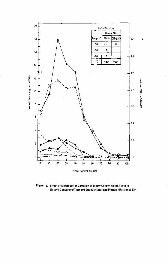
20 List o< Symbols
Temp C
Bi...)fy Alloy
Temp C Water Steam
200 _.- -X--
260 -•-
300 -•--•o -A- • -A-
i i i i _ 10 20 30 40 50 60 70 80 90 100
Nickel Conlenl. peiceni
Figure 12. Effect of Nickel on the Corrotion of Binary Copper-Nickel Alloys in Oxygen-Containing Water and Steam at Saturated Preuure (Reference 32).

<0.
30
l\ Z ° 20
10
I
—CORROSION RATE —CORROSION RATE
- J • . — , —
- r " ' „*.—. y*--- —-*
oa
o«
02 04 06
PHOSPHORUS CONTENT'. 0B 10
< K 2 0 in O c II O o
Figure 13. Effect of Phosphoruion the ZeroStreii General Corroiion Rate and the Slresj Corrosion Crtckind Behavior of Copper-Photphorut Alloy J Stressed in Tension at 10,000 p» m a M a m Ammoniacal Atmotphtic at 35C I Reference 33).

20 —
hr
-
• TPC t .
— \ • • 99 999°=Cu \
«*\
1 I I I ! 20 50 100 200
Timeiolaiiureinri
500 1000
~*H i Figure 14. Effect of ConiUnt-Load Tensile Stress on the Time to Failure for Annealed Tough-Pitch Copper and 99.999% Pure Copper Exposed to 10.05 V. Ammonium Hydroxide Solution it 70C (Reference 39).

004 005 006
unf O H concenlialion IM)
Figure 15. Efleci of Ammonium Hydroxide Concentration and Temperature on 1he Stmt-Corroiion Cracking Behavior of Annealed 99.999V Pyre Copper Stressed in Tension at 17.2 kg.mm' 2 (Reference 331.

tensile stresses were applied by the slow strain rate method. Cracking did not occur when the sodium nitrite concentration was equal to or less than O.OOiM (i.e., 69 mg/1). Increasing sodium nitrite concentrations (above O.OOIM) increased the susceptibility of the coppers to SCC. Susceptibility of the two coppers to SCC was reduced by deaerating the solutions, increasing the solution temperature to 80C, and increasing the strain rate.
CORROSION OP COPPER-BASE ALLOYS
The primary concerns regarding the use of copper-nickel and alpha aluminum bronze alloys in steam and water environments are general corrosion, stress-corrosion cracking, and intergranular corrosion. Although these alloys are susceptible to pitting attack by waters containing sulfides, this deterioration phenomenon has been restricted primarily to polluted cooling waters (esp., seawaters).
General Corrosion Copper-nickel alloys typically corrode in dry and good-quality
(43) wet steam at rates of less than 0.1 mpy. v The corrosion rates reported by Sato*"' for binary copper-nickel alloys exposed to steam at temperatures between 200 and 350C at saturated pressure are presented in Figure 12. These data suggest that the corrosion of copper-nickel alloys is somewhat facilitated by the presence of oxygen in the steam. This belief is supported by the results of Hopkinsonf4^) w n Q investigated commercially-available and laboratory-prepared 90-10 Cu-Ni and 70-30 Cu-Ni alloys in oxygenated, distilled-water vapor at 260C (Figure 16 ) . In general, Hopkinson's data reveal that, following an initial three-day period of high weight losses per unit area, the weight losses for the 70-30 Cu-Ni alloys do not significantly increase with increasing exposure time.
An aluminum bronze containing 10 w/o aluminum has been reported to corrode at about 1 mpy when exposed to 104C steam used to supply

600
500
C* 90 tnCOPPfh N't «£i
CB ftO?5COppf*>rtlt»fi C0MMEBCI4| v t i l
i 'oaocopptwxicnti
'.OUUFHCPHI V L I !
Cii" W|MC'*l Milt
l '0»CQ»PE(I*OC(
0 2 6 8 10 12 14 16 18 20 22 24 26 28 30
TIME OF EXPOSURE-DAYS
Figure 16. Corrosion of Copper-Nickel Alloy m Oxygenated Qistilfetf-fftttr Vapor ai260C (Reference 44}.
V.

a deaerator.
Reportedly, 70-30 Cu-Ni alloy has a corrosion rate of less than 3 mpy when exposed to electric utility plant boiler feedwater. This rate is somewhat higher than that reported by LaQue for a boiler feedwater at 198C (0.2 mpy; Table 1 ) , Feedwater heater temperatures, however, vary.
Definitive studies on the general corrosion of 90-10 Cu-Ni and 70-30 Cu-Ni alloys in high-temperature waters have been conducted by
f 4 40 — f 461 Hopkinson11**-'and Brush and Pearl. ' Binary copper-nickel alloys f 321 have been studied by Sato. '
water Hopkinson's results for oxygenated distilled/at 260C are given
in Figure 17. In general, these data indicate that following an initial seven day period of relatively high weight losses per unit area, the weight losses for 70-30 Cu-Ni alloys and high-purity 90-10 Cu-Ni alloy do not significantly increase with increasing exposure time.
The weight-loss data reported by Brush and P e a r l ' 4 4 ' for 90-10 Cu-Ni and 70-30 Cu-Ni alloys exposed to pressurized, high-purity, high-temperature, near neutral pH water containing 10 ppb dissolved oxygen are summarized in Table 5. These data suggest that both alloys corrode at nearly the same very low rate for a given temperature between 65 and 204C, It should be noted that the highest weight loss recorded by these investigators (49.6 mg.dm in 5093 hours; 0.23 mdd) corresponds to a corrosion rate of less than 0.04 mpy.
The weight losses recorded by Sato for binary copper-nickel alloys exposed to oxygen-containing water over the 200 to 350C range are given in. Figure 12. Increasing the temperature from 300 to 350C markedly increased the corrosion rate for alloys containing up to about 70 w/o nickel.

couMEnrtAt M L f
> *0 3 [ i C O P P [ O N O E l
U1MMIBUM MLi I
COMMfftCIAl M t | l
W MONEi ALlOMOD
v '[)30COPPEBNlCREl
frlUSilRO*
H K H O C O P W N H * l t PIUS ? l f t O * A * p ? MANGANESE
l A y o m i n n * u t , -
C , « « E n ( i i t « t , •
MIL|H(>uHlI«bE,*
i J lOrt-CflPFfft V . ' - l ,
HIGHFLIflLrvUEi,'
Si M « Q C O P " f B N . C n t .
MiCHHjHitf U ( \ «
4 6 8 10 12 U 16 IB 20 22 24 26 26 30
TJMC OF EXPOSURE-DAYS
f igurc 17. Corronon of Coppti Nickel Alloys in Oxygtnited Distilltd Water »t 26QC
(Reference 44|.

TABLE 5. CORROSION OF COPPER-BASE ALLOYS BY HlGH-TEMPERATURE, HIGHPUfllTY. NEUTRAL pH WATER C O N T A I N I N G ^ ppb DISSOLVED OXYGEN.
Average Descaled Weight Low. mg.'d m?
Monel Admiralty 9010 7030 70-30 Coppei-Nickei Tematriture. F 7>me, hr A»OY Btatt CoBDer-Nickei Copper-Nickel * f e
150 5093 .' 23.2 20.7 •• 11.7 200 5093 29.9 18.6 21.S 11.0 250 2750 97
5093 302 19.5 20.5 14 1 18.3 300 2750 332
5093 373 24.4 19.3 17.6 36.4 350 2750 188
5093 365 40.6 28.6 22.5 37.4 400 2750 285
5093 452 73.3 41.9 49.6 45.8
* Dash indicates that too little oxide appeared present to warrant descaling. "Specimens used for additional tests. Source: Reference 46. 1 -r
TABLE 6. STRESS CORROSION CRACKING TIME TO FAILURE FOR COPPER-BASE ALLOYS EXPOSED TO SATURATED STEAM AT 176 C AMD STRESS6Q AT 30,000 pii.
Alloy Time To Failure, hr.
5 A I . 9 5 C u 550 7 A I , 2 F e . 9 1 C u ISO 7AI , 2Fe.9?Cu.0 .35Sn > 3 0 0 0 SAI .92Cu 50 3 Si. 1 Mn, 95 Cu 200
Source: Reference 51.

At lower temperatures, Myers and Obrecht' 3 4' have reported the corrosion rate for 90-10 Cu-Ni alloy (i.e., Copper Alloy No.<70600) to be less than 1 mpy when exposed to 93C sodium-zeolite softened water flowing at 0.46 m.sec . Excluding the low-pH Honongahela River water data, Laque' 3 3' has reported similarly low corrosion rates (about 0.9 mpyf for 70-30 Cu-Ni alloy when exposed to a variety of domestic and industrial waters at temperatures up to 71C.
At 79C, an aluminum bronze containing 10 w/o aluminum has been reported to corrode at about 2 mpy when exposed to the boiler feedwater in V*deaerator.' 3 0'
The corrosion resistance of 70-30 Cu-Ni, 90-10 Cu-Ni and an aluminum bronze to aqueous environments containing relatively-high concentrations of ammonia have been reported by Tice and Venizelos (Figure 1 8 ) . ( 4 7 ' Of the three alloys, 70-30 Cu-Ni has the best resistance to "dripping" aqueous ammonia solutions containing 500 and 1000 ppm armonia. This observation regarding 70-30 Cu-Ni alloy is supported by the results of Thompson and Tracy* 3 8' who reported the corrosion rate for 70-30 Cu-Ni alloy to be 0.6 mpy when exposed to a continuously-renewed atmosphere containing 80% air, 161 ammonia and 4% water vapor at 35C (Figure 19). In the same environment, 90-10 Cu-Ni alloy corroded at about 46 mpy. The excellent resistance of: 70-30 Cu-Ni alloy to ammonia-containing aqueous environments has also been reported by Rawdon and Groesbeck.*48* when exposed to ambient temperature aerated and unaerated 3.5% (IN) ammonium hydroxide solutions, the corrosion rates for 70-30 Cu-Ni alloy were, respectively, 0.027 and 0.21 mpy.
Thompson and Tracy* ' have also reported corrosion rates for annealed binary alloys of copper and aluminum exposed to a continuously-renewed atmosphere containing 80% air, 16* ammonia and 4% water vapor (Figure 20). The corrosion rate is essentially independent of alloy composition for aluminum contents up to 8 w/o.
Corrosion rates for copper-nickel alloys in dilute nitric acid

Coroei 30 Nichfci
Cooper-10 Nickel
c Aiuniinum Bronze 2 j r
£ AlSFniDBI CObpe'
Alufninumfifass
Aamiraiiy Brass
7 4 6
Manmum Co'TOSion Rale THIS pe' yfcd'
Figure 18, Corrosion Rates for Copper-Base Alloys in Ammonia "Drip" Tests Conducted al Ambient Temperature I Reference 471.

50
40
30
~ 20
BREAKING TIME
« _ _ —CORROSION RATE
\
i BREAKING TIME
« _ _ —CORROSION RATE
/ i /
/
/
\
K^
- 1 • *•» ,, i —
/
^
08
oa
10 20
NICKEL CONTEXT,
30
Figure 19 Effect ot Nickel on the Zero-Stress General Cotroiion Rate and Stress-Corrosion Cracking Behavior ol Annealed Copper-Nickel Alloys Stressed in
Tension at 10.000 psi and Exposed to a Moist Ammomacat Atmosphere
jt35CIRe1er2nce3BI.

solutions apparently have net been reported in the technical literature. Very likely, these alloys behave similarly to that reported for copper,
Stress-Corrosion Cracking Alpha aluminum bronzes (e.g., Cu-6.5Al-2.SFe) are susceptible
to stress-corrosion cracking in ammonia vapor, steam at 82 to 260C, and high-temperature aqueous environments.' 4 9" 5 1' In ammonia vapor, the crack morphology is predominantly transgranular; intergranular cracking normally occurs in steam and the high-temperature aqueous environments.
Based upon tests conducted in 176C saturated steam where the material was stressed at 30,000 psi (constant load) in tension, the times-to-failure for a typical aluminum bronze (i.e., Cu-7Al-2Pt) have been on the order of 150 hours. { 5 1 ) The same investigators established that the stress-corrosion cracking of alpha aluminum bronze in steam and high-temperaturt aqueous environments could be prevented by small additions (i.e., 0.2 to 0.3 w/o) of either tin or silver to the alloy (Table 6). This observation culminated in the development of the commercially-available Aropco Grade 8 aluminum bronze. 1 5 1* Unfortunately, neither the tin nor the silver addition effectively mitigated the alloy's susceptibility to stress-corrosion cracking in ammonia vapor.
Sato and Nagata { 5 2 ) have reported that 90-10 Cu-Ni and 70-30 Cu-Ni alloys are susceptible to intergranular stress-corrosion cracking {IGSCC) when exposed to pure water and steam at 300 and 350C, At tensile stresses of 15 to 20 kg.mm"2, the IGSCC behavior of the two alloys was reported to be independent of the oxygen concentration (i.e., 0.1 to 0.3 ppm for the "degassed" and 40 to 70 ppm for the "oxygen-bearing") of the environment.
Thompson and Tracy t 3 8 ) have reported that annealed binary alloys of copper and nickel stressed in tension at 10,000 psi are somewhat susceptible to stress-corrosion cracking in a continuously-

renewed atmosphere containing 801 air, 161 ammonia and 41 water vapor at 35C (Figure 19).
Intergranular Corrosion It has been reported by Sato and Nagata* 5 2) that 70-30 Cu-Ni
and 90-10 Cu-Ni alloys experience intergranular corrosion in the absence of applied stress when exposed to steam/water in autoclaves at 300 and 35X>£ for 500 hours. Reportedly, the intergranular rate of attack was increased by stressing the specimens in tension} accelerated intergranular attack occurred above a certain "threshold-stress", the value of which appeared to be dependent upon the chemical composition of the alloy and its metallurgical condition.
Faber and Joynt' 5 3' have reported that stressed 90-10 Cu-Ni and 70-30 Cu-Ni alloys are susceptible to inttrgranular attack in "low" and "medium" oxygen content 901 sodium hydroxide solutions at 375C. Intergranular corrosion was not observed in the same environment when the oxygen content was "high."
REFERENCES
1. R.F. Tylecote, Jour. Inst. Metals, 78, 259 (1950-51). 2. A. Ronnguist and H. Fischmeister, Jour. Inst. Metals, 89, 65
(1960-61). 3. O, Kubaschewski and B.E. Hopkins, Oxidation of Metals and
Alloys, pp. 249-253 (London: Butterworths), 1962.
4. G. Valensi, Rev. Metal 1., 4S_, 10 (1948). 5. R.F. Tylecote, Jour. Inst. Hetals, 81, 681 (1952-53). 6. O.F. Hudson, T.M. Herbert, F.E. Ball and E.H. Bucknall, Jour.
Inst. Metals, 42, 221 (1929). 7. B. Lustraan and R.F. Mehl, Trans, AIME, 143, 246 (1941).

T.N. Rhodin, Jour. Air.er. Chop. 5or., T3, 3143 (1951). F.W. Young, J.v. Cathcart and A.T, Gwathmey, Acta Wet., 4_, 145 (1956). H.H. Uhlig, Corrosion and Corrosion Control, pp. 197-198 (New York: John Wiley and Sans, Inc.), 1971. R.F. Tylecote, Hetallurqia, 5_3, 191 (1956). G. Valensi, Pittsburgh International Conference on Surface Reactions, p. 156 (Pittsburgh: Corrosion Publishing Company), 1948. A. SrimVasan, D. Jagannathan, M.S. Hedge and c.N.R. Rao, Indian Jour. Chem., 18A, No. 6, 463 (December 1979). F. Gronlund, Jour. Chim. Phys., 53 , 660 (1956). J. Benard, F, Gronlund, J. Oudar, M. Duret, Z. Elektrochem., 63., 799 (1959). F.J, Wilkins and E.K. Rideal, Proc. Roy. Soc. (A), 128, 394 (1930). F.J. Wilkins, Proc. Roy. Soc. (A), 128, 407 (1930). G. Honjo, Jour. Phys. Soc. Japan, 8, 113 (1953), E.A. Gulbransen and J.W. Hickman, Trans AIME, 171, 306 (1947). A.H. White and L.H, Germer, Trans. Electrochem. Soc., 81., 305 (1942). E.A. Gulbransen and W.R. McMillan, Jour. Electrochem. Soc., 99_, 393 (1952). W.E. Campbell and U.B. Thomas, Trans. Electrochem. Soc., 91. 623 (1947). A. Ronntjuist, Jour. Inst. Metals, 9±, 89 (1962-63). J, Tobir,, Report No. GA-3349, General Dynamics Corporation, San Diego, California, February 06, 1963. H. Nishimura, Jour. Hin. Metal 1., Kyoto, 9, 655 (1938). M.D. Sanderson and J.C. Scully, Oxidation of Metals, 3_, No. 1, 50 (January 1971). N.B. Pilling and R. E. Bedworth, Industr. Engng. Chem., ]1_, 372 (1925).
28. A.P.C. Hallowes and E. Voce, Metallurgia Manchr., 34, 95 and 119 (1946). ~"
29. G.C. Wiedersum and E.A. Tice, Trans. Am. Soc. Mech. Enqrs., 87(A), 324, July 1965.
30. ASM Committee on Corrosion of Copper, Metals Handbook, 1, Properties and SElection of Metals, pp. 983-1005 (Metals Park, Ohio: Am. Sor. Metals), 1961.
31. M.J. Farber, J.Electrochem. Soc., 106, 751 (1959). 32. S. Sato, Sumitomo Light Metal Technical Reports, 5, No. 4, 242
(1964). 1 r
33. F.L. LaQue, Corrosion, 2£, 391 (2954). 34. J.R. Myers and M.F. Obrecht, Materials Performance, jl_2» No. 4,
17, April 1973, 35. R. Tunder, Report No. DF705L, General Electric Company,
Schenectady, New York, December 01, 1970. 36. A . H . Wagner and J.R. Myers, Corrosion, 2_6, 79 (1970),. 37. R.J. McKay and R. Worthington, Corrosion Resistance of Metals
and Alloys, p. 409 (New York: Reinhold Publishing Corporation), 1936.
38. D.H. Thompson and A.W. Tracy, Trans. AIME, 185, 100 (1949). 39. Y. Suzuki and Y. Hisamatsu, Boshoku Gijutsu, 23_, 29 (1974). 40. Y. Suzuki, Y. Hisamatsu, S. Morishima, Boshoku Gijutsu, £3, 477
(1974). 41. S.p. Pednekar, A.K. Agrawal R.w. staehle, J. Electrochem. Soc,
126, 701 (1979). 42. L.A. Benjamin, D. Hardie, R.N. Parkins, Report No.
83-06/SKBF/KBS, University o£ Newcastle upon Tyne, England, April 1983.
43. H.H. Uhlig (Editor), Corrosion Handbook, p. 95 (New York: John Wiley and Sons, Inc.), 1948.
44. B.E. Hopkinson, Corrosion, 20_, 80t (1964). 45. H.H. Uhlig (Editor), Corrosion Handbook, p. 85 (new York: John
Wiley and Sons, Inc.), 1948. 46. E.G. Brush and W.L. Pearl, Corrosion, .25, 99 (1969).

E.A. Tice and C.P. Venizelos, Power, 107, No. 11, 64, November 1963. H.S. Rawdon and E.C. Groesbeck, Technical Paper No. 367, 409, National Bureau of Standards, Washington, D.C., 1928. J.F. Klement, R.E. Haersch and P.A. Tully, Corrosion, 1_6, 519t (1960). J.F. Klement, R.E. Maersch and P.A. Tully, Corrosion, 21» 295t (1959). J.F. Klement, R.E. Haersch and P.A. Tully, Metal Progress, 7_5_, No. 2, 83, February 1959. S. Sato,afid K, Nagata, Boshoku Gijutsu, 23, 125 (1974). G, Faber and G.A. Joynt, Brown-Boveri Review, 54, 704 (1967).

DRAFT REPORT
COPPER AVAILABILITY AND COST CONSIDERATIONS A Survey Of Published Forecasts To The Year 2000
by
H. Stuart Lyman and 1.3. Servi
to
Lawrence Livermote National Laboratory Rockwell Hanford Operations
University of California Purchase Order 637005
from
Copper Development Association Inc. International Copper Research Association, Inc.
June 23, 1986
Copper Development Association Inc. Greenwich Office Park 2, Box 1840
Greenwich. CT 06836

PREFACE
This report was prepared in support of the 'LS. Department of Energy (DOE) program begun in 1984 to assess the feasibility of using copper-base materials for waste package containers in a nuclear waste repository. Within this DOE program, the Nevada Nuclear Waste Storage Investigations (NNWSI) and the Basalt Waste Isolation Project (BWIP) are evaluating oxygen free copper, deoxidized hiqh phosphorous cooper, an aluminum bronze (7 percent aluminum) and two copper-nickel alloys (90-10 and 70-30 comoositions). To aid the total copper feasibility effort, Lawrence Liv^rmore National Laboratory (LLNL) called on the U.S. copper and bnss industry, via A contract with Copper Development Association In:., to use its extensive data bases, technical associates and contacts to provide technical support and assistance to the DOE program. CDA and the International Copper Research Association, InT. (INCRA) set up a joint advisory group of specialists from both •mide and outside the copper industry to help carry out th* copper industry responsibilities to the I3QE program. This report on •wiilability and cost considerations is one product of the copper industry support effort.

TABLE OF CONTENTS
PREFACE SUMMARY BACKGROUND THE WORLD COPPER INDUSTRY
Copper Production Copper Fabrication Scrap Recycling Adding Value to Copper Products Copper Statistics U.S. Self-Sufficiency
THE OUTLOOK FOR COPPER SUPPLY AND COST CONCLUSIONS APPENDIX - SUMMARIES OF REPORTS SURVEYED
Brook Hunt Associates (1986) Bureau of Mines (1982) Bureau of Mines (1985) Bureau of Mines (1986) Canada Mines (1986) Charles River Associates (1986) Comraodities Research Unit (1985/6) Mining Journal (1986) Alexander Sutulov (1985) Alexander Sutulov (1986) United Nations (198 ) University of Arizona (19B4) World Bank (1984) World Bank (1986)

COPPER AVAILABILITY AND COST CONSIDERATIONS A Survey Of Published Forecasts To The Year 2000
SUMMARY An eKtensive review of 14 recent, diverse independent studies
on the outlook to the year 2000 for copper supply, demand and price carried out by eleven different government organizations, consulting Einns, financial institutions and universities revealed a unanimous consensus that:
1. Copper will be adequately available to satisfy a growing world demand to the year 2000, and
2. The price of refined copper will increase only a little from the current range aroung 65 cents per pound, and will never exceed 90 cents per pound in the forecast period.
There is some divergence of opinion on the demand growth rate. But, irrespective of the demand outlook, all forecasters predict that supply will keep pace with or exceed demand over the forecast period.
The U.S.A. is essentially self-sufficient in copper, since some 90 percent of copper demand has generally been satisfied by domestic orss and scrap over the recent past. In the future, the U.S.A. may rely a little more on imports of refined copper than in the recent past. At the same time, it will also depend more on'domestic recycled scrap, which between now and the year 2000 will tend to increase its share of total copper supply at the expense of refined copper.
BACKGROUND
The use of copper, or copper alloys, for containers for the underground disposal of U.S. spent nuclear fuel waste could require large amounts of copper. Depending on the design of the containers used, the copper needed for this application over a 25 year period would fall in the range of roughly 30,000 to 200,000 metric tons. Annualized, this would only amount to 1,200 to 8,000 metric tons per year, or .04 to .3 percent of total U.S. demand for copper and copper alloys, based on 1985 data. This represents an extremely modest increment in copper demand, especially considering the fact

that over the past 20 years the cyclical fluctuation in U.S. copper consumption has averaged 238,000 metric tons in each of the 14 years it has increased and 453,000 metric tons in each of the 6 years it has declined. Clearly the incremental demand for canisters will be almost insignificant, even when compared to the normal cyclical fluctuations in U.S. copper consumption.
Despite this, the absolute magnitute of the potential copper requirement, and a persistent perception by some that copper is a scarce metal subject to price and supply volatility, require that copper availability and cost considerations be examined in the long-range context of the U.S. civilian nuclear waste disposal program.
To do this, fourteen economic studies made by ten different organizations were reviewed in order to compare their conclusions and to ascertain whether a reasonable consensus exists among the professionals who made them as to the outlook for availability and price to the year 2000. Bight of the studies were publicly available and six were studies done privately by financial institutions or consulting firms which were made available to us for the purpose of preparing this report. A brief summary of each study appears in the Appendix.
THE WORLD COPPER INDUSTRY
A brief review of the structure of the copper industry can help put the data on copper availability and cost in perspective. As with all metals, the demand, i.e. usage or consumption, for copper each year is met partly by metal extracted from newly mined ore — primary copper — and partly from recycled scrap — secondary copper.
Copper ore deposits valuable enough to mine are widly scattered in areas of the earth of high seismic activity, coinciding with locations where the tectonic plates are subducted. A major fraction of these deposits ere found along the Pacific rim — in western
-2-

North and South America and the East Indies and Phillipines —and in the Canadian Shield. Other important deposits are located in Africa, especially Zaire and Zambia, the U.S.S.R., Poland and lesser deposits in Yugoslavia, Scandinavia and Iran.
The geographical distribution of copper ores given by nature provides for a reasonable supply-demand balance in the industrialized nations only in North American and the U.S.S.R. It results in a gross deficiency in supply in western Europe and Japan and a gross surplus in a few developing and less developed countries, mainly Chile, Zambia, Zaire and Peru.
Readily available scrap helps offset the supply-demand imbalance that prevails in western Europe and Japan and further improves the self-sufficiency that exists even without it in North America.
Copper Production
The ore from which copper is extracted contains from about half a percent — in the case of most U.S. mines — to a few percent of copper. It usually also contains valuable amounts of by-product molybdenum, silver and gold whose recovery partially offsets the cost of producing copper.
Copper ores are mined, milled (concentrated) and subjected to the pyrometallurgical or hydrometallurgical extractive processes of smelting and refining and electrowinning. Typically, more than half the cost of copper production is in the mining and milling and the balance in extraction and refining.
Copper mining and milling is carried out today by three main groups of operators:
-3-

1. Traditional free-world mining companies, which in recent years have been partially acquired by oil companies, and which produce about 37 percent of the world total.
2. The CIPEC group, of which Chile is the dominant producer company. CIPEC is an association of countries which are major exporters of copper: chiefly Chile, Zaire, Zambia and Peru. Directly or indirectly, governments influence the decision making oE the CIPEC producers. CIPEC, in its more than 2D years of existence, has never succeeded in any cartel-like action which it originally aspired to, perhaps because CIPEC countries account for only about 33 percent of world production.
3. CentraLly planned economies, of which the U.S.S.R. is the dominant copper producer, account for about 30 percent of totaL worLd production.
Host copper is also smelted and refined in the countries and companies that mine,and mill it. The balance is exported as "concentrate," which is about 304 copper, for smelting and refining in Japan or western Europe.
Copper Fabrication
To be useful, refined copper, sometimes referred to as "unwrought" copper, must be transformed into mill products such as strip, sheet, plate, rod, bar, tube and wire. These are generally and variously referred to as fabricated products, semi-fabricated products and semi-manufactures. They are either pure copper or copper alloy and they are manufactured in either wire mills or brass mills. Wire mills use refined copper only and produce high-conductivity wire for electrical use. Brass mills use some refined copper, but mostly recycled scrap in the U.S.A., and produce semi-manufactures used for corrosion resistance, heat transfer, structural and aesthetic applications in addition to electrical uses.

Foundries, which rely almost entirely on recycled scrap, produce copper and copper alloy castings. They are also an important segment of the total copper and copper alloy industry although they use only a small amount of refined copper. Copper powder producers and copper chemical producers complete the picture.
Scrap Recycling
Scrap generated during the production of refined copper and of mill and foundry products is recycled internally. This "home" or "run-around" scrap is not reported in the industry statistics. The scrap which is reported is the "new" scrap which derives from the manufacture of parts and components by the industrial customers of the brass mills, wire mills and foundries, and the "old" or "obsolete" scrap which derives from retired, worn out and abandoned products, equipment and systems.
Adding Value to Copper Products
As described, to be useful unwrought copper must be transformed into mill and foundry products. These, in turn, must be fabricated further into parts, components and systems. At each step of the way value is added.
If the copper ore in the ground is assumed to have zero value, the total value added at the end of each step in the evolution of a product is approximately as follows, today, in cents per pound.
Concentrate - 48 " Blister Copper - 59 Refined Copper - 64 Electrical Wire - 83-90 Copper Plate - 100-140 Alloy Plate - 110-200 Centrifugally Cast Alloy - 230-360
-5-

The cost of fabricated components and systems, including nuclear waste containers, depends on the cost of semi-manufactures and on several other factors that are component-specific. These include design, scrap generation, forming, joining, finishing and final inspection. These subjects are covered in a companion report on fabrication alternatives. In that analysis, the final cost of fabricated containers is estimated, assuming current technology, to fall in the range of $28,000 to $33,500 per container.
Copper Statistics
Copper and copper alloy consumption in the U.S.A. totalled 6,188 million pounds (2.8 million metric tons) of wire mill, brass mill, foundry and powder products in 1985. In addition, 246.3 million pounds of copper (.1 million metric tons) went into chemicals, the alloying of other metal systems and other industries. Of the total mix of copper and copper alloy products consumed in the U.S.A. each year, almost exactly 90 percent is copper, per se, and 10 percent is alloying metal. A chart tracing the flow of copper from mine to market in the U.S.A. statistically appears in Figure 1.
Using 198S data as an example, of the total copper consumed each year about 70 percent is refined copper and 30 percent directly used scrap. Of the refined copper portion, about 19 percent comes from recycled scrap resources, leaving only about 57 percent of total copper consumption in the U.S. coming each year from newly mined copper. This statistical balance, in metric tons, is summarized in Table 1.
World statistics are less certain than U.S. data, but for the major copper producing companies and the major industrialized consuming countries they are accurately known.
Copper is a world commodity which is traded freely on commodity exchanges, principally in New York and London. This means that the price of copper changes daily according to the classic principle of
-6-

Supply of prima-v copper from mine to consumption by wire rod mills, brass mills, ingot matters, foundries, powder plants and other industries-COPPEfl COhTfhl INHiunn*. 4 ilinrl Ion,
Consumption of metals by wire rod mills, brass mills, ingot makers, foundries, powder plants and other industries. v i m ccUCNf iiPrt,jvi«-K m ^™i tn*«.
r*
ktrniiu ui-r
Supply of secondary copper from receipt to consumption by brass mills, ingot makers, foundries, powder plants and other industries.
WIT stent nut!
•Ltd must
f •WW* _i i rutu \1_
Supply of wire mill, brass mill, foundry and powder products and their consumption: in the end-use market*-ULT4L COHtEHT n
i**+ >;Mtfcrt
*M OmtHKiM.
4"
H UlCr*YU \ * (UCMtWCI
r iMMit I
?P e [HCCNT[ f l r IhouViTidj:
Figure 1. The Flow of Copper from Mine to Market in the U.S.A. in 1985.

TABLE 1. A SUMMARY OF U.S. COPPER STATISTICS
FROM MINE TO MARKET - 1905
Millions of Metric Tons
Refined Production from Newly Mined Ores .94 Refined from Imparted Material .01 Refined from Stocks .09 Refined from Scrap .36
TOTAL REFINED PRODUCTION 1.40 Imports of Refined, net .31 Consumption of Refined Stocks .20
TOTAL REFINED CONSUMPTION 1.91 Direct Use of Scrap .83
TOTAL COPPER CONSUMPTION 2.74 Alloying Metal Used .29
TOTAL METAL CONSUMED 3.03 Used in Chemicals, Alloys and Other -.11 Metal Stocks and Other - .30 Imports of Mill & Foundry Products .19
CONSUMPTION OF MILL & FOUNDRY PRODUCTS 2.81
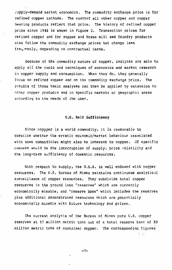
supply-demand market economics. The commodity exchange price is for refined copper cathode. The costsof all other copper and copper bearing products reflect that price. The history of refined copper price since 1946 is shown in Figure 2. Transaction prices for refined copper and for copper and brass mill and foundry products also follow the commodity exchange prices but change less f ret,j?ntly, depending on contractual terms.
Because of the commodity nature of copper, analysts are able to apply all the tools and techniques of economics and market research to copper supply and consumption. When they do, they generally focus on refined copper and on the commodity exchange price. The results of these basic analyses can then be applied by extension to other copper products and to specific markets or geographic areas according to the needs of the user.
U.S. Self Sufficiency
Since coppper is a world commodity, it is reasonable to question whether the erratic economic/market behaviour associated with some commodities might also be inherent to copper. Cf specific concern would be the interruption of supply, price volatility and the iong-term sufficiency of domestic resources.
With respect to supply, the U.S.A. is well endowed with copper resources. The U.S. Bureau of Mines maintains continuous analytical surveillance of copper resources. They subdivide total copper resources in the ground into "reserves" which are currently economically minable, and "reserve base" which includes the reserves plus additional demonstrated resources which are potentially economically minable with future technology and prices.
The current analysis of the Bureau of Mines puts U.S. copper reserves at 57 million metric tons out of a total reserve base of 90 million metric tons of contained copper. The corresponding figures
-7

Centi per pound
10 —
Price of Refined Copper in the U.S.A.
1940 1950 I960
Seurctr E & W i£^mming «nd Mmiflf Jautft«4) M«ch 1 I K
1970 1980 19B5
Figure 2. U.S. Copper Price Trends Since World War I I . Real prices rose through the mid-50's, were relatively stable through the early 70*j and hive declined since.

for all of North America are 90 and 150 million metric tons. These numbers may be compared to the U.S. consumption (including imports) of newly mined refined copper of 1.4 million metric tons in 1985.
The U.S. has about 16.8 percent of total world copper reserves and 18.0 percent of the total world reserve base, according to the Bureau of Mines analysis, which shows world reserves at 340 million metric tons and the world reserve base at 500 million metric tons today. In comparison, the U.S. accounted for 16.7 percent of the world consumption of new refined copper of 8,4 million metric tons in 19B5.
The above evaluation of reserves might be construed to mean that U.S. copper resources would only last Eor 64 years, or that world copper supplies would be exhausted in about 60 years. This interpretation is misleading on two counts. First, the history of resource analysis shows that copper reserves do not necessarily decline with the passing of time. Extraction and use each year does of coarse reduce reserves by that amount. However, resource evaluation *lso depends on the assumptions made about price and the economics of mining each given ore body and changes in these assumptions can cause significant changes in the analytical results from year to year. Meanwhile, advances in the technologies of exploration and recovery tend to cause reserves to increase with passing time.
In addition to mine reserves there is another U.S. copper resource: recyclability , the mine above ground. Nearly half of U.S. copper consumption, 43 percent, came from recycled scrap resources in 1985. Reliance on scrap resources fluctuates from year to year depending on current economic conditions and the comparative advantage to each copper consumer of using scrap versus new copper. The inevitable long-term trend, world wide, is in the direction of using more scrap as more copper products are produced and the of reserve base of copper above ground in the form/products in use expands.
-3-

Copper is uniquely recyclable among structural materials. Its recycle value is so great that premium grade secondary copper has a value of up to 90 percent that of primary metal, compared to competing materials whose scrap values generally range from a maximiw of about 60 percent down to nothing. The reasons are simple. It is technologically easy and economically attractive to recycle copper, and the resulting metal is identical to primary copper refined from ore.
Domestic availability and the need to rely on foreign sources of supply are also pertinent considerations tor an application so important to the national interest as nuclear waste disposal containers. Although copper is an international commodity, the U.S. is essentially self-sufficient in copper, a fortunate fact sometimes not fully appreciated.
Over the past twenty years the U.S. has averaged about 90% in net total copper and copper alloy self-sufficiency. This despite extremely unfavorable world trade conditions for U.S. copper and brass producers recently which caused imports to reach unprecedented high levels in 1983, 1984 and 1985. The recent high point in self-sufficiency, 97%, was reached in 1975. it could be attainable again whenever world economic conditions favor it or if a national need for self-sufficiency were to emerge.
Copper self-sufficiency can be expected to continue to fluctuate in the years ahead, in the immediate future at a level below 90 percent. The U.S.A. has relatively low-graie ores and high priced labor. Thus, in times of low copper prices U.S. mines tend to become marginal sooner than foreign mines and their operations are suspended and their output replaced by imported copper. When prices strengthen, U.S. mines tend to resume production as imported copper becomes relatively less attractive. One of the most striking developments in the U.S. copper industry in the past four years, however, has been a dramatic increase in productivity made necessary by stagnant prices and increasing foreign competition. By some
-9-

measures productivity has nearly doubled at the U.S. copper mines which are operating today compared to four or five years ago.
U.S. copper supply and consumption dynamics, in a free market environment, are driven by a large number of intricate economic and business interrelationships. How they play out year by year will determine the extent of imports, the mixture between scrap and new copper used, and myriad other supply-consumption variables, all of which can be expected to fluctuate, but within the reasonable band experienced in the recent past. Ever, so, one thing remains certain: The U.S.A., endowed with abundant copper resources and equipped with superior recovery and production technology, will be self-sufficient in copper supply whenever free-market economics favor that situation and can be made self-sufficient at any time the national interest demands it. In short, self-sufficiency can be expected to find whatever level is in the nation's best interests.
Of the alloying elements potentially required for copper alloy canisters, nickel and aluminum both come from outside the U.S.A. Fortunately, nickel comes only a few hundred miles from Canada, and aluminum a like distance from the Caribbean, among other places.
THE OUTLOOK FOR COPPER SUPPLY AND COST
The crucial copper availability question for the nuclear waste storage program is the outlook for supply and cost in the late 1990's when the construction of containers and the storage of waste will begin. To provide guidance on this question we consulted the literature and surveyed organizations and individuals which were likely to have made serious studies of the outlook for copper: consulting firms, financial institutions, government agencies, universities and copper companies. We looked only for studies made after 1930. Eight publicly available studies were found and access was gained, for the purpose of this report, to six private, or as yet unpublished, studies. The fourteen studies were from the following sources:
-10-

Consulting Firns; Brook Hunt & Associates Limited in the United Kingdom (Chertsey, Surrey) which has iollowed the world copper scene for more than ten years, publishing for its clients a quarterly review which continually updates the long-term and short-term outlook for copper. Brook Hunt also does many special economic and market studies on copper for individual clients and subscribers.
Charles River Associates Inc. (CRA) in Boston, Massachusetts which has done many economic and market studies of copper and other metals for government and private-sector clients and which has recently completed a major proprietary study of copper supply and demand.
Commodities Research Unit (CRU), London-based with a New York office, which for many years has published Copper Studies, a monthly periodical reviewing copper supply-demand economics and which also carries out special proprietary studies on copper, and on other metals and minerals, for individuals and client groups,
Alexander Sutulov in Santiago, Chile, a long-time analyst of the copper industry who has recently published (Intermet Publications) two proprietary reports, Copper at the Crossroads and Copper Price Outlook to the Year 2000.
Financial Institutions; The World Bank, which has analysts who continually follow copper and which publishes a comprehensive review of the copper industry every two or three years.
Government Agencies: The U.S. Bureau of Mines, which of course follows copper continuously and which publishes a review on copper each year as a chapter in the Bureaus' publication Mineral Facts and Problems, as well as special studies on the economics of copper supply and demand.
The Canadian Department of Energy, Mines and Resources which functions much as the Bureau of Mines and which recently published a forecast on copper availability and costs.
-11-

The United Nations Conference on Trade and Development which publishes studies on copper from time to time.
Universities: The Univerisity of Arizona, where Professor R. Newcomb prepared a study, published in Metal Bulletin Monthly, on the future of the world copper industry.
No studies of general scope and coverage were found in contacts with copper producer companies, which in fact tend to rely on organizations such as those listed above for objective analyses of the general context within which the individual companies carry out their own company-specific studies. Discussion with appropriate specialists in these companies revealed a general consensus in accord with the results of the recently made studies which we obtained and reviewed for this report.
Needless to say, each of these analyses has its own unique perspective and approach.
Also, they each focus on different time horizons — mostly 1995 and 2000 — and on different copper products — new refinedj total refined; and all forms, including direct use of scrap — and they express prices in different constant-dollar terras. Nonetheless, it is quite easy to array and compare the essential results of the several studies in their own terms, without resort to any artificial normalization of them. This is done in Table 2 for copper demand and Table 3 for price ranges.
The forecast for world copper demand for refined copper, that is, total refined copper from both primary (new) and secondary (scrap) sources, for the several studies range from 11.8 to 14.9 million metric tons for the year 2000. For those projecting free world demand the range is 8,1 to 9.5 million metric tons for the year 1995. Those projecting world demand for copper in all forms, that is, total refined copper plus the direct use of scrap, forecast a range of 11.5 to 18.6 million metric tons for the year 2000.
-12-

TABLE 2. SUMMARY OF COPPER DEMAND PROJECTIONS TO THE YEAR 2000,
Otmano. million metric tons
Source Year Product 3emana
Univ. ot AritonaH9B4l
Break Hum Aiioc. 119861
U.S. Bureau ol Mines 119801
11985)
(19361
CHA (19861
CRU 119851
Internet 11985}
119361
World Sink 119341
2000 Refined Norm AmHiea 1.3 Worm u s
All Forms
All Form* 2000 All Form* World 15.0 Primary Refined World 13.1 All Forms USA 2.a
2000 Rilmed World 14 1 USA 2.9
2000 All Forms Fret World 11.5 2000 Retinrtd FrM World 8.1
1995 Refined Free World ai
2000 All Forms World ise Free World M l
Refined World 14 9
2000 All Forms World 1*3 Pnmirv Refined World no
1995 Refined World n.a 1995 Free Worta 9.5
CRA - Cnsrles River Associates CRU - Commodities Research Unit
TABLE 3 . SUMMARY OF REFINED COPPEfl PRICE RANGE PROJECTIONS TO THE YEAR 2000.
Price Range, cams oer oouna
Source Time Period Constant Dollar Year Price Range
Brook Hunt Associates 11986) Onto* Mines (1986) 1990s 1985 60-20
1990s 1985 80-90
Charles River Associates (19S6I 1980i 1985 75-80
1990s 198S 80-90
Commoaititj Research Unit (1985! 1995 1984 75
Internet (19861 1980s 1985 65-70
1990s 1985 80-90
World Bank 11934) 1990 1983 71.5 1995 1983 78.0
11986) 1980s 1984 63 -64 1990-95 1984 64-?«

More significant than the variations among the forecasts for copper demand is the fact that all the analysts were unanimous in their independent conclusions that supplies of copper would be readily available when needed to meet the demand they projected.
This shared conclusion that copper availability is not likely to tighten significantly between now and the year 2000 — except for unpredictable short periods of supply interuption due to things such as natural disasters and strikes, and except for wars or other unpredictable major upsets in international relations — leads to a consensus among the analysts that copper availability will continue to be more than ample for the rest of the century. This in turn led thorn to conclude that the cost of copper, that is, the commodity exchange price for refined copper, would range from 64 to 90 cents per pound (in 1985 dollars) during the decade of the '90's (Table 4).
CONCLUSIONS
The general conclusions derived from an extensive survey of fourteen recent independent studies by ten government agencies, consulting firms, financial institutions and universities are as follows:
1. All forecasters project some growth but relatively weak demand for the balance of the 1980's» and growing demand leading to a somewhat firmer market for copper in the 1990's.
2. Overcapacity of supply will continue to prevail into the 1990's. Whenever indications of a potential shortfall in supply become evident, expansion projects now in the planning stage will be activated promptly and the supply-demand balance will be maintained.
3. All substantial expansions of copper supply will occur outside North America, and a substantial fraction will occur in Chile, which will become increasingly dominant among the world producers of primary copper.
4. Because U.S. costs of production are higher than those abroad (especially in Chile), the U.S.A., which has until recently imported only some ten percent of its copper needs, is likely to become somewhat more dependent on foreign sources.
-13-

5. In the U.S.A., an increasing fraction of copper demand will be satisfied by old scrap, which is abundantly available from domestic sources.
6. Overall, there is no concern about the availability of copper in the U.S.A., barring unpredictable emergencies.
7. The price of refined copper will rise gradually in the 1990's from the current range around 65 cents per pound, but will never exceed 90 cents per pound by the year 2000, expressed in 1985 dollars.
-14-

DRAFT REPORT
PROPERTIES OF COPPER AND COPPER ALLOYS UNDER CONSIDERATION FOR NUCLEAR WASTE CONTAINERS
to
Lawrence Livermore National Laboratory Rockwell Hanford Operations
University of California Purchase Order 637005
from
Copper Development Association Inc. Internat ional Copper Research Association Inc.
June 23, 1986
Copper Development Association Inc. Greenwich Office Park 2, Box 1840
Greenwich, CT 06836

PREFACE
This report was prepared in support of the U.S. Department of Energy (DOE) program begun in 1984 to assess the feasibility of using copper-base materials for waste package containers In a nucLear waste repository, within this DOE program, the Nevada Nuclear Waste Storage Investigations (NNWSIJ and the Basalt Waste Isolation Project (BWIP) are evaluating oxygen free copper, deoxidized high phosphorous copper, an aluminum bronze (7 percent aluminum) and two copper-nickel alloys (90-10 and 70-30 compositions). To aid the total copper feasibility effort, Lawrence Livermore National Laboratory (LLNL) called on the U.S. copper and brass industry, via a contract with Copper Development Association Inc., to use its extensive data bases, technical associates and contacts to provide technical support and assistance to the DOE program. CDA and the International Copper Research Association, Inc. (INCRA) set up a joint advisory group of specialists from both inside and outside the copper industry to help carry out the copper inlustry responsibilities to the DOE program. This report on properties is one product of the copper industry support effort.

PROPERTIES OP COPPER AND COPPER ALLOYS UNDER CONSIDERATION FOR NUCLEAR WASTE CONTAINERS
The thirteen tables which follow cover five copper metal compositions, in wrought and cast form, which are under consideration for use as container materials in the U.S. program for civilian nuclear waste disposal (Table 1) and present some of their pertinent physical and mechanical properties (Tables 2 through 1 3 ) .
Table I. Copper Metals Under Consideration 2. Density 3. Coefficient of Linear Thermal Expansion •4. Specific Heat 5. Thermal Conductivity 6. Modulus of Elasticity 7. Tensile Strength 8. Yield Strength 9. Elongation
10. 10,000-Hour Creep strength 11. 100,000-Hour Creep strength 12. 10,000-Hour Rupture Strength 13. 100,000-Hour Rupture Strength
In the mechanical property tables, Table 7 through 13, provision is made for data from four different sources for each alloy:
a. Evaluated data from INCRA Monograph XII* . The monograph contains the results of a survey of fifty-one selected references containing elevated temperature property data on copper and copper alloys. Published in December 1983, the monograph was prepared by specialists at BNF Metals Technology Centre. In selecting from the monograph for inclusion here, care was taken to choose data representing heavy sections and soft tempers appropriate to the canister application, uata on cast a n o y L S D ^ U U are cor separately cast test bars.
b. To augment the monograph data, the literature was searched via the CDA Copper Data Center. Very few data were found which extended the BNF survey results. What was appears on line b. in the tables.

c. To further extend the data, a test program has been undertaken by CDA as part of the fiscal year 1936 copper industry support effort to the DOE nuclear waste container program. The aim of this work is to prepare a uniform set of elevated temperature tensile property data on the five copper met3ls under conditions of section size, form and temper which are appropriate to the waste container application. To date, testing has been completed only for two materials: cast alloys C95200 (aluminum bronze) and C964Q0 (70-30 copper-nickel). The results (average of five tests) are shown on line c. of Tables 7 through 9,
d. One approach to nuclear waste container desiqn involves reliance on the ASME Boiler and Fressure Vessel Code1 . Reflecting that fact, and for convenient comparison with the data described above, Code maximum allowable stress values are shown on line d. in Tables 7 through 13. The data shown are for the thickest plate included in the Code and for as-cast castings.
In discussing the data available for nuclear waste disposal container design, Martin Prager, a consultant to CDA in this ar*a with special background and knowledge about copper (and also associate director of the Metal Properties Council) identified six considerations related to data and to Code allowables:
1. The Code usually contemplates hardware which will have a lifetime measured in tens of years rather than hundreds of years: For example, allowable stresses in the time-dependent regime are based on 100% of the stress for 1% creep in 100,000 hours (or similar values, i.e. 10" per hour, 0.1% per 10,000 hours, etc.). For copper materials rupture criteria are not limiting factors.
2. For DHP copper the time-dependent regime in the Code begins at 300F; for 90-10 copper-nickel it begins at 500F; and for 70-30 values up to 700F are time-independent. The temperatures noted would be lower if the contemplated exposures at the design temperatures were very much longer than 100,000 hours. Additionally, the allowable stresses would be correspondingly lower than those now in the Code.
3. The allowable stresses now in the Code in the tiiiit-ijcueinjeiic regime are oasea on cne coiiowing: For Copper No. C12200, DHP Copper: The creep properties are for fine-grain annealed material; coarse-grain values would be significantly higher, at least 50% higher.

For 90-10 Copper-Nickel: The creep properties / annealed material with low iron content. Material with high iron content deserves higher values,which would raise the temperature at which time-dependent behaviour begirs. For 70-30 Copper-Nickel: The Code data base recognizes the properties of ultra-low iron content material produced before the relatively higher iron content materials now used were developed. For very long term service it may be important to quantify this effect.
4. There are precedents in the Code for assigning hiqher allowable stresses to materials for which qrain size or composition are controlled within narrowed ranges.
5. For OF Copper all elevated-temperature allowable stresses would have to be creep-limited if many of the properties reported are accepted. For the cast versions of pure copper, the presence of deoxidizers should justify higher allowable stresses. Some of the creep values in the tabulations may be douDtful on the basis of the literature data.
6. It may be that the values used in the assignment of current allowable stresses are unduly conservative due to the manner by which they were determined. If true minimum (secondary) creep rates wore not achieved,the Code values, would be low. Extrapolating these low values for longer time service would result in greater penalties.
These Code considerations undoubtedly also apply to other alloy systems as well as copper.
It seems clear that attention should be focussed more closeiy on mechanical properties in the 1987 program. Additional testing will surely be in order as will the application of parametric interpretation and further analysis of the currently-available data. There are now highly precise, rapid methods for determining low creep rate data which are likely to be needed. Different approaches are probably needed for .NNWSI and for BWIP. The first ste;; sUould be discussions between those two projects and the CDA/INCRA project,

including Dr. Prager. In the meanwhile, we are continuing to gather data via elevated temperature testing of specimens of the candidate copper metals cut from annealed heavy-section plate and >r-.-om centrifugally cast cylinder walls.
REFERENCES
1. C.H. Thornton, S„ Harper and J.E. Bowers, A Critical Survey of Available High Temperature Mechanical Property Data for Copper and Copper Alloys, SNF Metals Technology Centre, INCRA Monograph XII (DecomDer 1983)
2. ASHE Boiler and Pressure Vessel Code, Section VIII -Division i, Pressure Vessels, The American Society of Mechanical Engineers, (1983 Edition, Winter 1985 Addenda)

Table I , Copper Merels Nuclear Waste I
Copper or Copper Alloy No. Description
C10200 OF Copper C8OI00* C12200 OHPCoDper
caiioo" C61300 AluDlnum 8ron2*
C95200*
C70600 90-10 Copper-Nickel
C9620O*
C 71500 70-30 Copper-NI eke I
C96«00»
Under Consideration for llsposal Canisters
Nominal Compostlon Cu P Fe M HI
99.95
99,95
99,95 .025
99.90
90 3 7
88 1 9
8B.6 1.4 10
88.6 1.4 10
69.5 .5 30
69 1 30
•Cast Material

TabI* 2. Owtllty
(tensity Coppw or
CoDD»r A11oy No. C10200
o/cn 8.9 ~
1
lb/In' 0.321
C80100* 8.94 0,325
CI 2200 8.9 0.321
CBII00« 3.94 0.325
C61300 7.8 0.200
C9H0O* 7.6* 0.276
C70600 a.9o 0.J20
C96200* 8.94 0.325
C7I500 8.95 0.325
C9M0O" B.94 0.323
"Cast Matarlal

Tatjle 3. Coefficient of Untar Therwal Expansion
Cofiper or Coefficient of Linear Thermal E»panslon, per nwo C (Fl Copper Alloy Ho. Z5-I00C 77-7I2F SO-iOOC 68-392F 20-300C 68-37?F
CIOZOO 0.0000168 0.00000933 O.0O00173 0.00000961 0.0000177 0.0QOO0983
C80100* — — 0.0000169 0.000009*
CI 2200 O.0QOOI6B 0.00000933 O.OOOOI73 0.00000961 0.0000177 0.O000O9B3
C81100* - - -- - 0.0OO0I69 0.000009*
:61500 0.000016 0.000009 " — 0.000017 0.000009
C9520O" -- « « — 0,0000162 0.000009 C70600 - »- - 0.000017 0,000009
C96200* - - - 0.0000173 0.0000095 C71500 — — - - 0,000016 0,000009
C9H00* . . . . . . _ 0,000016 0,000009
•Cast Material

Tabl* 4 , 5
Copgar or SptclMc Copoar M 1 oy No. 20C(68F)
C10200 0.09ZI
C80100* 0.092
C12200 0.0921
CBIIOO* 0.090 C61J00 0.10 C95200* 0.09
C70600 0,09 C96200" 0.09 C71500 O.09 C«*00» 0.09
*C»st Mittrlal
Hie Hwt
. cal/o dag C fBtu/lb iaq F) 100CI2I2F> 200C(392F1
0.0939 0.0963
0.0939 0.0963

Tabt« 5. Tharnal Conductivity
Thyinal Conductivity, cal/cm /em 5 dw C (Btu/ft / f t h dw F) Cop par or fwaptrarura
Coapw Allay No. 20C 68F IQQC 2I2F 200C 392F 300C 57ZF C10200 0.94 227 0.92 225 — — 0,90 217
C8010Q* 0.934 226 - — — - - -
CS220O 0,80-0.93 195-225 -
CeilOO' 0.826 200
C6I30O 0.14-0.17 34 -41 ~ - - 0.20 48
C9H0O* 0.12 29.1
C70600 0.12 29 - - -
C9620O' 0.108 26
C71500 0.07 17
C96400* 0.068 17
•Cast Matarlal

TabU 6. Modulus of ElasTlctty (Typical)
Modulus of Elasticity (Annaalad) Coppar or
par AMov "o t
117,200 ksJ
C10200 117,200 17,000
caoioo* 117,000 17,000
CI 2200 117,200 17,000
C81100* 117,000 17,000
C61300 120,000 17,400
C95200* 101,000 15,000
C70600 135,100 19,600
C96200' 124,000 18,000
C7I500 151,700 22,000
C96400* 145,000 21,000
•Cast Matarial

Ua\* I , Ttni lU Sfr^ngin
Tanilla Stranat* - »/aa i s . I . ) , Hi icmrcwvi
Coppar w uclant raoc
I2I2F1 HOC KXC
(302FI I3WF) S. I . C w l , S
JOT (572FI
33(C 1662F)
" i . l . Cult.
tone I752F)
Mlor NO, 5.1 . Cwt. S . I . Cult. S. I . Cult. S. I , Cult, S. I . C w l , S i.J. Cult.
33(C 1662F)
" i . l . Cult. 5 .1 . Cm' .
CID200 a, o. : ; i <:.i m 29,1 is< 23.1 i u » . « U ; 21.0
C80IOO a. b. 112 Z5
C12200 a . 214 33.9 216 31.3 1M 2 6 . ) IB) 27.9 176 23.9 b. 21,0 12,0
3,S S.J 3.1 4.0 J,0
CM100 a. b. 112 !5
CS130O a, S I 73.3 111 » .6 t l i t l IS1.7) 301 <3.7 (26M 131.31 231 J0.9 tl9*> (76.91 | H 22.1 b, c. «. 16.3 16.3 16,) 16.3 16,3 16.) 15,«
• C96200 a. 374 «3,2 Ml) UO.OI 33a 76,» [497) I72.i1 1461) 167,0) (121) 161.11
t . c 63.0 « . ' . 1 . 19.7 13.7 l ( .» 11.9 11,2 11.2 14.2
C70600 a. 323 <6.1 1302) (43.61 ( 2 » ) 141,•) 276 ID.O 12701 I 3 M 1 263 39.1 299 37.0 291 36.4 6. C.
». 10.1 9.7 «,J 9,5 9,0 1.1 >.)
C7IJ0O a. Ml 33.3 1333) (30.41 1391) 146.9) 322 46.7 13161 141.9) 310 43.0 502 <5.e 270 42.1
C9S400 I . b. 469 66
56.9 94.6
a, Eaaluataa cm Iraa Item iwieoratn I I ) , Ralaranca I . Data lalacfad fo rapr.tant xwi Mctloni ant annaalvl eondltlwa approprlata to th» nuclaar vaata confalnar application,
b. Intftvltfual data valim 'roar ttii svbirin«t Iffararura, e, C0a tatt ra lul t i 119661 lor annaalaa thick sactlon M t a r l a l . 1 , ASKE Bollar ana PrHiurt i n w l Coda annua alloaadla i t r a n valval, (or coaparlid, Ralaranca 2. Data ara tor rnlqkait
ainaalaci ( lata or ai-catt eaitliuji.
'MI«rpolartta/a.vaDolarao valval in parantrtasan
Cast Matarlal

labia e. Ilald Strangtti
rtal« Strangm, 0,11 O f l n t <nro«gntl, I l . l l Olltar (Cut ) , fl/na (5 ,1 ,1 , kl l (Cultorard
Ccopar or IMC IXC JOCC 2VE 3O0C IKE
(mutant 1212ft I302H I J « f l l « J f l H U H H62FI J OX (THf l
Alloy W . S . I , Cult. S . I , Cull . S . I , Cm' . S.I. Cull . S . l . Cult, S . I , Cutt. S . I , Cus1. S. I . Cult.
affix a. b, M 9.6 66 9.6 4« 9.1 » >. I X M
CB0ID0 a. b, 62
CI2200 a. 60 1.7 3' ! .« I I 7.4 49 ' .2 47 4.8 b .
CW40TJ a. b. 2JS
6.7
C81100 a. b, 52
C6IJCO a, ; i ( J6.0 2J» M.J 12401 131.01 244 33.4 I2"> 33.5 243 33.3 230 34.5 6. c, 1 . to.} 16.3 16.) 16.3 16.3 16.3 13.9
C93200 a. b.
C70600 a. 127 19,4 ( I 1 » 116,4) 1103) I I ! .? ) H 13.9 199) 11*.*I IDS I4.» 109 I'.7 109 l ) .a b.
C96200 a. b.
C71J00 a. 160 23.2 11430 (21,1) 11361 (19.71 127 IIS.4 (1211 116.41 127 IB.* 122 17.7 119 17.1
9.4
a. EvaloatM oata Iroa IfCRA Mgiufraoh X I I , Ba'aranea I, Data Mlaclad to raaraaant na«« sactloii an! annaalatf coflHirlois approprlata to TM naclaar *atta contatnar amplication,
9. l-hjl.laual o.ra n i v a l >ria t m oubllikas lltararura. e. CD* *ast ratult i (1966) lor afHwalM thick lacflan Mtar la l , d. *S*«- Bollar m Praiaur* Vaisal Coda oawlauai allpatbl* i l r m valuai. lor coaoarlaoi, Ralaranca 2. (lata or» lor trrfckasT
amaalao pier* or as-cotr cairlftgi.
(Mrarpolarad/avrrapcla'ao valval In pararwiawjl

Tcblt 9. ElonqfeHon
Elongation, ptrctnt
Ccpptf or Al»bl«ftt I00C
I2I2F1 ISOC
< 3orf i JOOC 2HC
(JMFI (4J2F) S . I . Cult. S. I . Cu»t.
HOC IV2FI
5 .1 . Cust,
»oc I662FJ
<occ I7S20
Allov no. S. I . CU51, S. I . Cull, S. I . Cult.
JOOC 2HC (JMFI (4J2F)
S . I . Cult. S. I . Cu»t.
HOC IV2FI
5 .1 . Cust, S. I , C U M , 5,1. Cult.
CI 0200 «. 6.
CSDIOO 9. B. c, d.
C12200 ,9.
C8II0O a. c. 40
C61J30 a. SI
C9520O a. 49 (1)1 42 |40) |28) (20) b.
C70600 1 . 54 <JJI |J|) » [451 0. c. a.
C96200 I . B. c. a,
CJ1500 t . 52 (15) (to) M (40) 5. c. 0.
C9640O a. 6. 2g =- 3!
a. E«ali»1«d data Irm ItCM Kxngrttli » l l , Flaftranci I . Data U I K 1 M to raprMtnt tiitvy nctlona and annttlM condition! tpprtarnfa to tnt nuclHr m m contain* n t l l t a t l o n .
0. Individual datt valval I r m ttia tubllsnad l l t t r a t i r t , c. CM t « t r n a l l l !1»B6> lor tniwala* thltk. gtctlon •« tar 111, a. «S«E lollar and F r a n m W i l l CoM « « » u t l l m O l * afrtat valutf, for eottarlaon, RtftraMt 2, Daft art for tMckMt
annttlad Plata or at-caat ut t fnaa.
(litarpclattd/aatrapolAttd valuat In partnrnasaa)
Calf Kafarlal
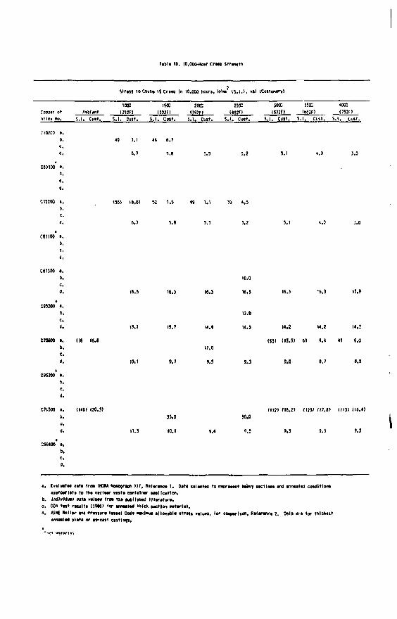
rat i * ID. 10,000-HOW Crup Str«nqtti
Str4js To CBUIO I f Cr«p In 10,000 hours, U/tm IS,1,1, ksl ICusTaHSry)
Cooptr or AnM*nt S. I . Cmt.
1000 HOC I2I2F) (302F1
200c 2srx sooc <WF> (4J2FI I572F)
JSOC I662F)
«ooc 1J52FI
Alio* No, AnM*nt
S. I . Cmt. S. I . Cull. S . I . Cult. 5.1. Cult. S . I . ClKt. S. I . Cust. S . I . Cult. S . I . Cult.
49 1,1 lb 6,7
M ' .» 5.5 !,2
4.
C I " M ». US! I8.0> 52 1,4 19 7.1 !0 4,J I .
3.0
C613M «. 6.
C95200 i ,
'• " • ' I5.T 11,7 14.) |«,J |4.2 14,3
C70MO •. lie IM (551 Clj.j) « 9,4 4) 6.0
' • W.< ' . ' M 9,3 9.0 6.7 J.J
C96200 »,
C7I500 i , (1<0I 120.37 rit2> (16,17 (IMF 1)7.17 (113) (16.47 &• JS.O 30.0
10.0
16.3 16,]
12.0
I4,« 14.)
17.0
M 9,3
13.9
10,1 9.4 9.*
C9640O B. b.
• . Ev«lHt«4 d i t i I r a IHCftA MoAOQflph XI f, f l i f imte* 1 . Qit i loltctod to roprMtnt hoiirf iK t lon i md innulta conditions •Pvreprlttl to Aw n K t w m h ) contllfMT lotIIco'ton.
6. IMttMml »•»» vilgw trot » » •vtllfMe' l l t n t v r o . c. CM t u t raultt M9H> (or M A M I M tmck wet loo M t i r l i l , a. ASIti BallW 404 ft-fiiuro V H H I Codf w l n M 4ll4Dlb1« i t r o u valuta, For caaporlion, R»l«r«n£t 2. D»t4 i r t (or thlcdvit
annMltd s l i t * or tt~e4lt cistlnqi.
' ""turnl

Tibia I I , 100,000-Hoor Craao Stranqth
Strajj to Cfcuit I I Craap In 100,000 hour*, N/n*> (S.1,1, kl l <Cu»1Maff>
Cobpar or Aihblant S. I . Cult.
I TO I ICC 200C 230C KOC (2I2FI (302FI 092FI U»2F) U72FI
HOC «ooc I752FI
Alloy No. Aihblant
S. I . Cult. S . I . Cast. S . I . Cmr. S. I . Cust. S . I . Cult. S . I . Cust. 5 .1 . Cult. S , l . Cult.
C10200 s. b. H6I l« . I ) (431 («.2I
6 . 7 *.» '.» 4,0.
tM) |T.8> 151) 17.«> KM I6.SJ
CSIIOO I . b.
C1J200 a, b.
C70600 a. 0.
5.1 4.0
16.3 18.3 16.3 10.3 16.3 16.3 U . t
15.7 19.7 14.9 11.3 14.2 14,2 14.2
9.7 9.3 9.3 9.0 0.7 8,5
11.3 ID.) 9.4 V.J 9.1 9.3 9,J
a. Evaluatad data trcm IICM Honograati i l l . Rataranca i . Data aalactad to rapraiant haavy lactlona and annaalad condltloni appr.oerlata to fha fluelaar aaita conralnar application,
b. Individual pvta *ali*» irem ttta wbllibad Htaratura, c. CDA tair raiul t i (19KI lor anmlat tMck taction • a l a r m , d. ASK Bollar and PraMura vaiial Coda w l M al lonbla i t r a n valun. lor comparison, Rataranca 2. Data ara <or t h l c u i t
atnaalad Plata or as-cait eaitlnai.
'C.t,,.,v.*»,»„ v>l'i»4 !•> nl
Cu t Hatarl il

Ttbla 12. lO.OOO-wur Ruptura strangtr,
Strata to Cauia Ruptura In 10.000 houra, N/im <$,!»>. htl ICuitoaarYl
Coppar or Amblant too: two ?«c ? ™ sooc
I2I2F> O02F) (J92F1 (4I2F) I5J2F) 350C
S. l . Cult.
ioac <"2F>
Alloy No, S.I . Ctrtt. S. I . Cutt. S. I . Cutt. S. I . Cult. S . l . Cuit. S . I . Cult,
350C
S. l . Cult. S. l . Cult.
C10200 a, b.
ceoIM a.
1115) 115.11 196) '13.91
6.7 5,a 5.1 <,0 i.o
C12200 a, b.
109 24.1 144 20,9 10) D.2
5.5 '.a
CBIIOO a. b,
C61300 a, b.
C9520O a. b.
C7060O a. b.
09(200 a. b.
16.3 16,! I ( ,J 16.3 IO.J 16.) U.9
15.7 13.7 11.9 K.5 I I .Z (<,2 14,2
172 24.9 91 11,2 41 1.9 54.0
10.1 9,7 9,9 9,3 9.0 I.T ».?
275 39.9 220 JI.9 174 23.2 149,0! (49.0)
11.3 10.1 9.4 9.3 9.3 9,3 9.3
C964M I . b.
a, Fjuluttan Ufa (ron IICRA Monograph X I I , ifetaraoca 1. Oata lalactad to rapraiant haayy tactions and annaalad condition! apprep'-lata to tha nuclaar watta contalflar application.
D, Individual data valval t r « tha publtinao lltaratura. c. C0» t»%t raiult j | l 9 » r tor amaalad thick taction •atar la l . d. «SMC BoMar and Praiiura tai ial Coda iwclnai alloaabla i t r a i i v a t m , tor nxparlion, nifartnea 2, Data ara lor inlck.tt
annoalad Plata or ai~calt catting!.
'r»tr«p ioiit*'i v i'ift? I" r*.ro^*"i;osJ

labia I ) , 100,000-Hoor Knotura Slranotn
Strata to C a m ftaptura In 100,000 hourt. H/m (5 .1 .1 , kll (Cu l tMr r l
^oepar or Anolaaf IKK
(JlSfl I5IE
(JOJfl I00C
(3MFI S. I . Cult,
2XE 300C (IMF) (S7JFI
5 .1 , Cult. M , Cult. IM2FI
$ .1 . Cult, I11JFI
Alloy No. ',.1. Cull. S . I . Cult. S . I . Cult.
I00C (3MFI
S. I . Cult,
2XE 300C (IMF) (S7JFI
5 .1 , Cult. M , Cult. IM2FI
$ .1 . Cult, 4 . 1 . Cul l .
(121) 1 I M I (111 110,1)
6.7 3.6 9.3 ?.I
•«0100 a.
c i 1100 a. b.
(ISO) 121.11 IIMI 115.7)
«.7
CHIO0 a. 6.
C70SM a. b.
IS.) IB,]
H.7 19.7
10.1 1.7
I t . )
I M
I t . )
14.)
129.0)
U.J
H . I U.2
1120 117.9) (99) 17.91 lt.0 S.J
1.7
I3.»
1.9
11.9 10.1
M l . M
».a
2Jf 34.9 IM 27,1 (*».«: 150,0) (20.11)
».J
IH.OI
a. E.aluaiaa <ata Iron IfCM aunajraan X I I , Dataranca I . Oata aalaetaa to rooraiant toaav faction ta« amtaalaa cowltloni aaarearlata to tna nuclaar aaata contalnar aatllcatton,
b. Itdlvloaal data tralvaa Iron raa puollatiaa lltaratvra. c. CD* taat raaalta I1*WI lor aowalad thick aactlgn aatarlal, a*. ASiat lollar ana Praaaura VHaal Cotfa snlaiai alloaabta itrata valuai, lor eoaparlavi, Aalaraaca 2. Data ara lor thlekait
wiaalad oleta or as-eait caitlnoi.
,4tt Hattrlal
*UJ.GOVE«NMENT fHIMlNC OmCE: ttH . 7I5-HV3MH