Background: Coal Gasification Technology Carrier Performance Recyclability of Commercial Fe 2 O 3...
10
Chemical Looping Gasification Fanxing Li and Liang-Shih Fan* Department of Chemical and Biomolecular Engineering The Ohio State University Oct. 8th, 2008 Sulfur By-Product Sulfur By-Product Fly Ash By-Product Fly Ash By-Product Slag By-Product Slag By-Product Steigel and Ramezan, 2006 IGCC Efficiency: ~ 33% with CO 2 control Background: Coal Gasification Technology Chemical Looping Gasification – Basic Concept CO 2 Reducer C x H y Metal Oxide H 2 O Metal Oxidizer H 2 O H 2 MeO + Fuel Æ Me + CO 2 + H 2 O Me + H 2 O Æ MeO + H 2 Fe 2 O 3 H 2 O H 2 Fe Air Hot Spent Air C x H y O z CO 2 + H 2 O Fe 3 O 4 Sequestration Syngas Chemical Looping (SCL) Concept 1. Reducer 2. Oxidizer 3. Combustor
-
Upload
nguyendien -
Category
Documents
-
view
216 -
download
0
Transcript of Background: Coal Gasification Technology Carrier Performance Recyclability of Commercial Fe 2 O 3...
Chemical Looping Gasification
Fanxing Li and Liang-Shih Fan*
Department of Chemical and BiomolecularEngineering
The Ohio State University
Oct. 8th, 2008
Sulfur By-Product
Sulfur By-Product
Fly Ash By-Product
Fly Ash By-Product
Slag By-Product
Slag By-Product
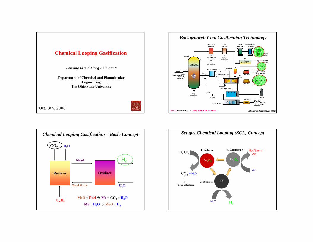
Steigel and Ramezan, 2006 IGCC Efficiency: ~ 33% with CO2 control
Background: Coal Gasification Technology
Chemical Looping Gasification – Basic Concept
CO2
Reducer
CxHy
Metal Oxide
H2O
Metal
Oxidizer
H2O
H2
MeO + Fuel Me + CO2 + H2O
Me + H2O MeO + H2
Fe2O3
H2O H2
Fe
Air
Hot Spent AirCxHyOz
CO2 + H2O
Fe3O4
Sequestration
Syngas Chemical Looping (SCL) Concept
1. Reducer
2. Oxidizer
3. Combustor
To Steam Turbine
Coal
Candle Filter
Hot Gas Cleanup
Sulfur Byproduct
Oxidizer
CO2
Steam
H2 (450 PSI)
Hot Spent Air
O2
N2
Compressor
Gas Turbine Generator
Fe3O4
Fe
Fe2O3
BFW
Fly Ash
Raw Syngas
Compressor
Air
Reducer
Hot Syngas
Particle Makeup
Purge
Air
Com
bustor
BFWCO2
and Trace H2S, Hg
To Steam Turbine
Coal
Candle Filter
Hot Gas Cleanup
Sulfur Byproduct
Oxidizer
CO2
Steam
H2 (450 PSI)
Hot Spent Air
O2
N2
Compressor
Gas Turbine Generator
Fe3O4
Fe
Fe2O3
BFW
Fly Ash
Raw Syngas
Compressor
Air
Reducer
Hot Syngas
Particle Makeup
Purge
Air
Com
bustor
BFWCO2
and Trace H2S, Hg
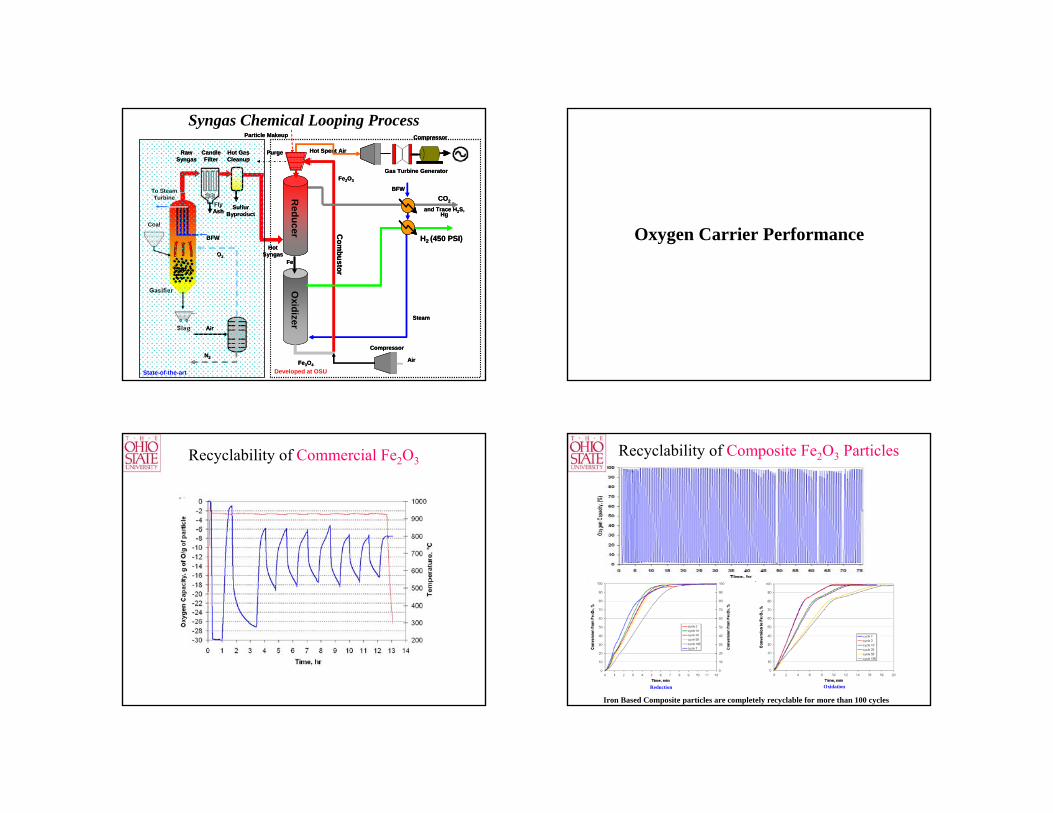
Syngas Chemical Looping Process
Developed at OSUState-of-the-art
Oxygen Carrier Performance
Recyclability of Commercial Fe2O3
Iron Based Composite particles are completely recyclable for more than 100 cycles
Reduction Oxidation
Recyclability of Composite Fe2O3 Particles
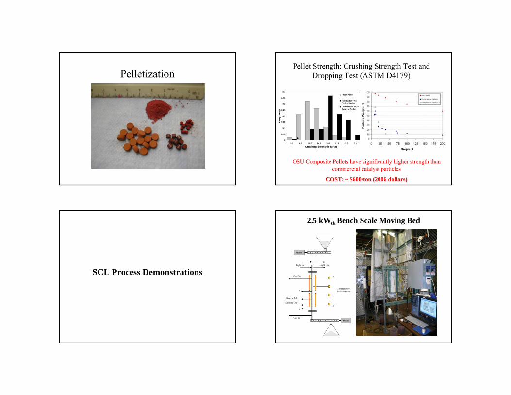
PelletizationPellet Strength: Crushing Strength Test and
Dropping Test (ASTM D4179)
OSU Composite Pellets have significantly higher strength than commercial catalyst particles
COST: ~ $600/ton (2006 dollars)
0
0.05
0.1
0.15
0.2
0.25
0.3
0.35
0.4
3.0 6.8 10.5 14.3 18.0 21.8 25.5 5.1Crushing Strength (MPa)
Freq
uenc
y
Fresh Pellet
Pellet after TwoRedox Cycles
Commercial WGSCatalyst Pellet
SCL Process Demonstrations
2.5 kWth Bench Scale Moving Bed
Light In Light Out
Gas In
Gas Out
Gas / solid
Sample Out
Temperature Measurement
Motor
Motor
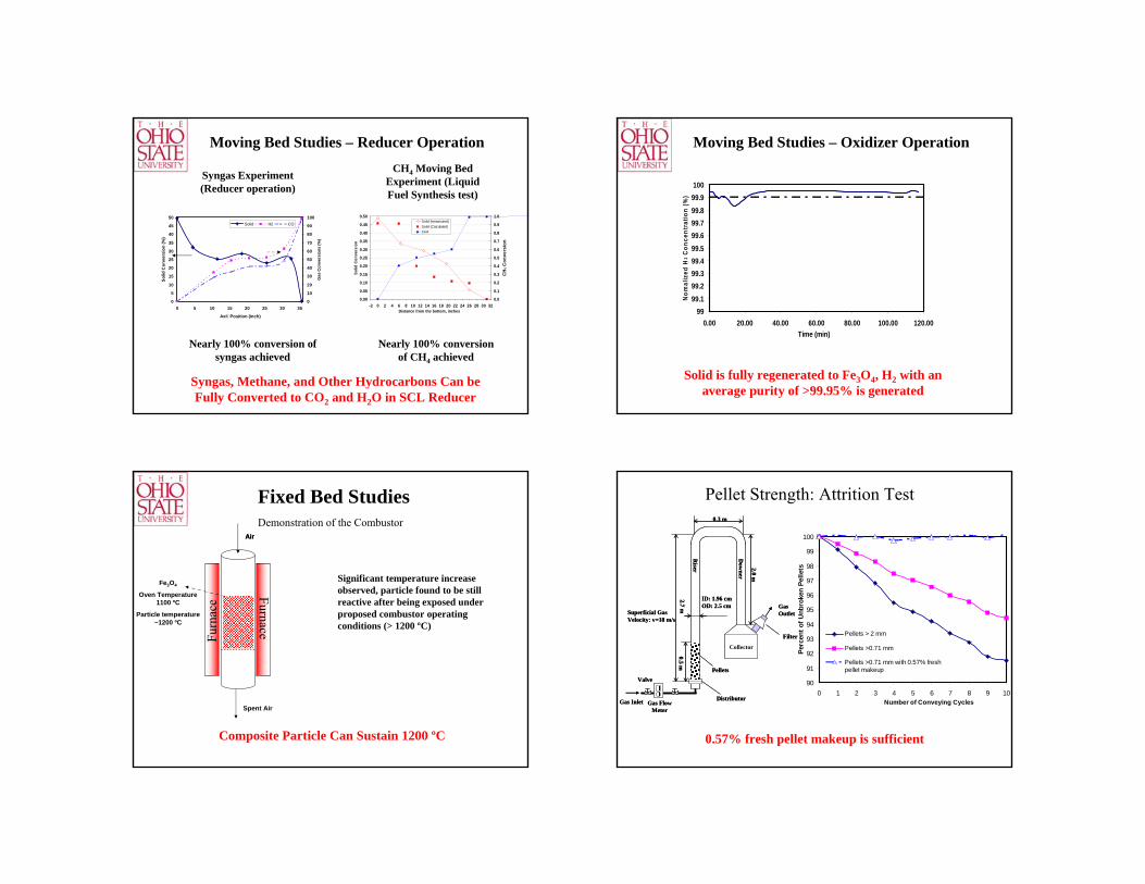
Moving Bed Studies – Reducer Operation
0
5
10
15
20
25
30
35
40
45
50
0 5 10 15 20 25 30 35
Axil Position (inch)
Solid
Con
vers
ion
(%)
0
10
20
30
40
50
60
70
80
90
100
Gas
Con
vers
ions
(%)
Solid H2 CO
Nearly 100% conversion of syngas achieved
Syngas Experiment (Reducer operation)
0.00
0.05
0.10
0.15
0.20
0.25
0.30
0.35
0.40
0.45
0.50
-2 0 2 4 6 8 10 12 14 16 18 20 22 24 26 28 30 32Distance from the bottom, inches
Solid
Con
vers
ion
0.0
0.1
0.2
0.3
0.4
0.5
0.6
0.7
0.8
0.9
1.0
CH 4
Con
vers
ion
Solid (meassured)Solid (Calculated)CH4
CH4 Moving Bed Experiment (Liquid Fuel Synthesis test)
Nearly 100% conversion of CH4 achieved
Syngas, Methane, and Other Hydrocarbons Can be Fully Converted to CO2 and H2O in SCL Reducer
9999.199.299.399.499.599.699.799.899.9100
0.00 20.00 40.00 60.00 80.00 100.00 120.00Time (min)
Nom
aliz
ed H
2 Con
cent
ratio
n (%
)
Solid is fully regenerated to Fe3O4, H2 with an average purity of >99.95% is generated
Moving Bed Studies – Oxidizer Operation
Furn
ace Furnace
Fe3O4
Oven Temperature 1100 ºC
Particle temperature ~1200 ºC
AirAir
Spent Air
Significant temperature increase observed, particle found to be still reactive after being exposed under proposed combustor operating conditions (> 1200 ºC)
Demonstration of the Combustor
Fixed Bed Studies
Composite Particle Can Sustain 1200 ºC
Pellet Strength: Attrition Test
90
91
92
93
94
95
96
97
98
99
100
0 1 2 3 4 5 6 7 8 9 10Number of Conveying Cycles
Perc
ent o
f Unb
roke
n Pe
llets
Pellets > 2 mm
Pellets >0.71 mm
Pellets >0.71 mm with 0.57% freshpellet makeup
0.57% fresh pellet makeup is sufficient
Collector
Gas Flow Meter
Valve
Gas Inlet
Pellets
Distributor
Filter
Riser
Dow
ner
0.3 m
ID: 1.96 cmOD: 2.5 cm
0.5 m2.7 m
2.0 m
Superficial Gas Velocity: v=18 m/s
Gas Outlet
Collector
Gas Flow Meter
Valve
Gas Inlet
Pellets
Distributor
Filter
Riser
Dow
ner
0.3 m
ID: 1.96 cmOD: 2.5 cm
0.5 m2.7 m
2.0 m
Superficial Gas Velocity: v=18 m/s
Gas Outlet
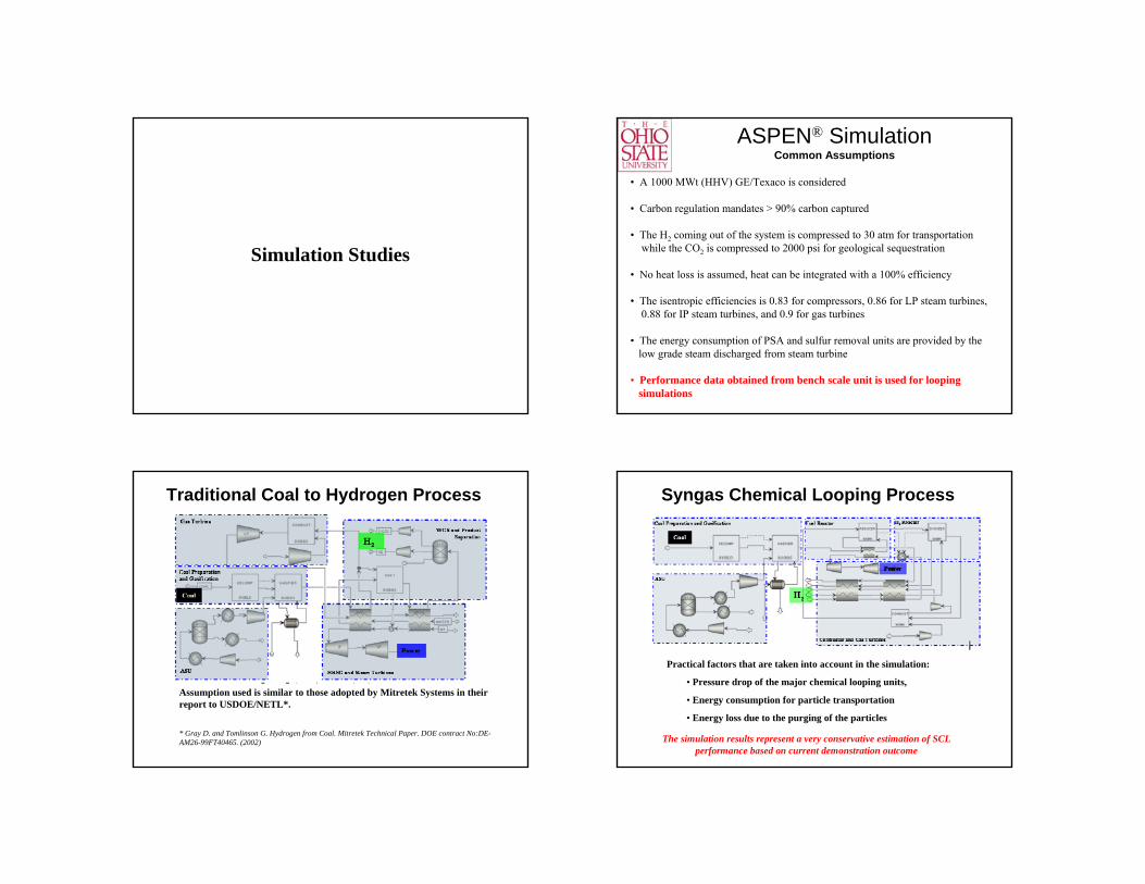
Simulation Studies
• A 1000 MWt (HHV) GE/Texaco is considered
• Carbon regulation mandates > 90% carbon captured
• The H2 coming out of the system is compressed to 30 atm for transportationwhile the CO2 is compressed to 2000 psi for geological sequestration
• No heat loss is assumed, heat can be integrated with a 100% efficiency
• The isentropic efficiencies is 0.83 for compressors, 0.86 for LP steam turbines, 0.88 for IP steam turbines, and 0.9 for gas turbines
• The energy consumption of PSA and sulfur removal units are provided by the low grade steam discharged from steam turbine
• Performance data obtained from bench scale unit is used for looping simulations
ASPEN® SimulationCommon Assumptions
Traditional Coal to Hydrogen Process
Assumption used is similar to those adopted by Mitretek Systems in their report to USDOE/NETL*.
* Gray D. and Tomlinson G. Hydrogen from Coal. Mitretek Technical Paper. DOE contract No:DE-AM26-99FT40465. (2002)
Syngas Chemical Looping Process
Practical factors that are taken into account in the simulation:
• Pressure drop of the major chemical looping units,
• Energy consumption for particle transportation
• Energy loss due to the purging of the particles
The simulation results represent a very conservative estimation of SCL performance based on current demonstration outcome

63.1252.6956.5Efficiency (%HHV)66.238.90Net Power (MW)
14.2412.3614.20Hydrogen (ton/hr)
1009090Carbon Captured (%)132.9132.9132.9Coal feed (ton/hr)
SCLConventional
Co-ProductionConventional Max H2
Comparison Between SCL and Traditional Coal to Hydrogen/Electricity Process
SCL process can increase the efficiency of State-of-the-art coal to hydrogen process by 7 – 10%
ASPEN® Simulation
Coal to Liquids Applications
Syngas Chemical Looping in CTL Applications
BFW
Coal Pretreatment
Candle Filter
Sulfur Byproduct
O2
N2
BFW
Fly Ash
Raw Syngas
Red
ucer
Oxi
dize
r
High Pressure
CO2
Air (Pneumatic Conveyor)
Steam
Pure H2
Fe
Fe2O3
Steam
Air
Warm Clean Syngas
H2/CO = 2:1
C1-C4 and Unconverted Syngas
Product Separation
C5 – C14
C17 and above
Hyd
rocr
ack
er
Cold Clean Syngas
H2/CO = 0.5
Separator IINaphtha
Diesel
Water
Generator
F-T Reactor
Heat Exchanger
Mercury Removal
Hg
SteamSpent Fe2O3 Powders
Fresh Fe2O3Pellets
Air
Steam
Steam
Com
bust
or
H2
Process (ASPEN) Simulations
Source: Noblis Systems
Liquid Fuel: 12,008 BBPD
Coal: 4,820 TPD
2.5 Bbl Fuel/Ton of Coal
Cleaning/Cooling
Gasification/Quench
BFW
H2Reactor
F-TReactor
H2/H2O
BFW
ProductSeparation
Gases
Upgrading
GasesNaptha 3,822Diesel 8,186
LP steam
HRSG
BFW
Dryer Compressed CO2
SteamTurbine 147.2 MW
FilterExpander
Water
15.5 MW
DepletedAir
HotH2O/CO2
SulfurPolish
FuelReactor
Depleted Air
H2O/CO2
Air
MP steam Steam
6
51 7 9
8
12
11
16
17
13 14
20
19
18
15
10
2.4 MW Net 160.3 Plant162.7 MW
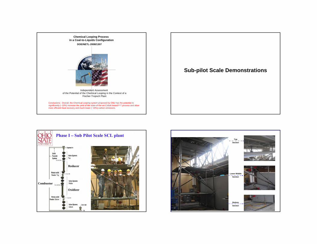
Chemical Looping Process in a Coal-to-Liquids Configuration
DOE/NETL-2008/1307
Independent Assessment of the Potential of the Chemical Looping in the Context of a
Fischer-Tropsch Plant
Conclusions: Overall, the Chemical Looping system proposed by OSU has the potential to significantly (~10%) increase the yield of the state-of-the-art Cobalt based F-T process and allow more efficient heat recovery and much lower (~19%) carbon emissions.
Sub-pilot Scale Demonstrations
Reducer
Oxidizer
Combustor
Top
Section
Lower Middle
Section
Bottom
Section

Other Chemical Looping Gasification Processes
Coal-Direct Chemical Looping Process
Air Compressor
Expander
Coal
Ash/Spent Particle
H2
CO2
BFW
Steam
H2
CO2 + H2O
Fe2O3
Fe3O4
FeC
ombustor
Generator
Reducer
Oxidizer
H2S Remoal
Sulfur Byproduct
Hg Removal
Fe/FeO
Makeup Particle
Fe/FeO
Hot Spent Air
Fe2O3
Steam
N2
Air O2
Reducer Configuration
Coal (and O2)
Char gasification and particle reduction:
FeO + H2 Fe + H2OFeO + CO Fe + CO2
CO2 + C 2CO
Fe2O3
Coal devolatilisation:Coal → C + CxHy4
Particle reduction :CH4 + Fe2O3 → CO2 +
H2O + FeO
Fe
CO2 + H2O
Enhancer (H2, CO2, H2O)
Reaction Initiation:H2 + FeO Fe + H2OH2O + C → CO + H2
CO2 + C 2CO
2CO + 2FeOx 2FeOx-1 + 2CO2
1CO2
2CO2 + 2C 4CO
1 CO2
2 CO2
4CO + 4FeOx 4FeOx-1 + 4CO2 4 CO2
CO2 + C 2CO
2CO + 2FeOx 2FeOx-1 + 2CO2
1CO2
2CO2 + 2C 4CO
1 CO2
2 CO2
4CO + 4FeOx 4FeOx-1 + 4CO2 4 CO2
Fuels &ChemicalsAir
Separation
Hydrogen
FuelCell
Steam
Slag SteamTurbine
Gas Turbine
AirCompressor
Stack
HRSG
RotaryCalciner
INTEGRATEDWGS +H2S
+COS + HCLCAPTURE
Generator
Gasifier
BFW
To SteamTurbine
CO2
Air
AirOxygen
CaO
CaCO3
SteamH2+O2
Calcium Looping Process
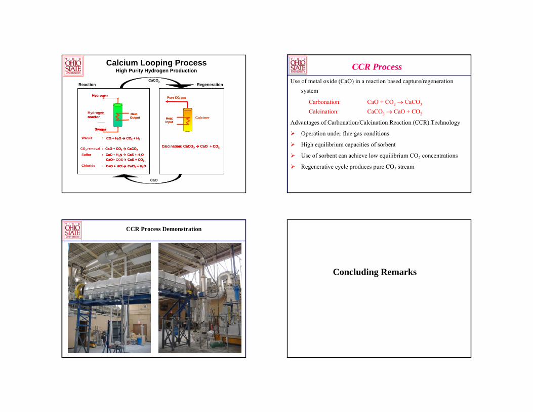
Calcium Looping ProcessHigh Purity Hydrogen Production
HeatOutput Heat
Input
Pure CO2 gas
Calcination: CaCO3 CaO + CO2
CO + H2O CO2 + H2
CaO + CO2 CaCO3
CaO + H2S CaS + H 2OCaO+ COS CaS + CO2
Chloride CaO + HCl CaCl2 + H2O
Syngas
Hydrogen
reactor
RegenerationReaction
HeatOutput Heat
Input
Pure CO2 gas
Calcination: CaCO3 CaO + CO2
WGSR : CO + H2O CO2 + H2
CO2 removal : CaO + CO2 CaCO3
Sulfur : CaO 2S CaS OCaO CaS + CO2
: CaO + HCl CaCl2 + H2O
Syngas
Hydrogen
Hydrogen reactor
CaCO3
CaO
Calciner
Use of metal oxide (CaO) in a reaction based capture/regeneration system
Carbonation: CaO + CO2 → CaCO3
Calcination: CaCO3 → CaO + CO2
Advantages of Carbonation/Calcination Reaction (CCR) Technology
Operation under flue gas conditions
High equilibrium capacities of sorbent
Use of sorbent can achieve low equilibrium CO2 concentrations
Regenerative cycle produces pure CO2 stream
CCR Process
CCR Process Demonstration
Concluding Remarks
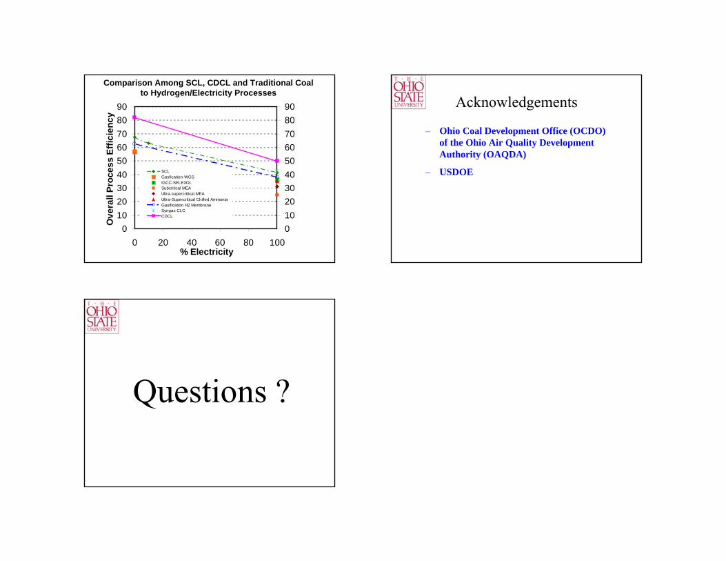
0102030405060708090
0 20 40 60 80 100% Electricity
Ove
rall
Proc
ess
Effic
ienc
y
0102030405060708090
SCLGasfication-WGSIGCC-SELEXOLSubcritical MEAUltra-supercritical MEAUltra-Supercritical Chilled AmmoniaGasification H2 MembraneSyngas CLCCDCL
Comparison Among SCL, CDCL and Traditional Coal to Hydrogen/Electricity Processes
– Ohio Coal Development Office (OCDO) of the Ohio Air Quality Development Authority (OAQDA)
– USDOE
Acknowledgements
Questions ?