BACKGROUND - axone.in · This Case study would make the student understand the following concepts...
16
© 2017 Axone technology Services www.axone.in 4th floor, CK Plaza, L-152, 5th Main, 14th Cross, Sector 6, HSR Layout, Bangalore 560 0102 INDIA BACKGROUND CCNA (Cisco Certified Network Associate) has become the first certification the students do, to seek a career in networking. In the absence of a proper university degree like BE (Civil engineering), BE (Mechanical) for network engineering, CCNA by Cisco Systems has become the launch pad for budding network engineers. The students from any educational background do CCNA certification to seek a career in computer networking. CCNA over years has grown more than its intended purpose of producing professionals to manage Cisco routers and switches. It is now seen as a certification program that gives entry for anyone to start a career in networking. The students expect to become competent networking engineers and find jobs to manage the computer networks of different organizations by getting the CCNA qualification. Our CCNA+ (R&S) program is designed with lot of care and passion considering the following factors a. There is no university degree for Network engineers b. CCNA is the launch pad for a career in networking c. The students should also be exposed to other networking concepts which are not included in the CCNA syllabus to get a proper foundation knowledge in networking d. The students should learn networking, practicing with lot of real life case studie s in the lab The Salient features of our CCNA program 1. 101 LAB CASE STUDIES a. The students learn how to plan, design, install, configure, troubleshoot and maintain the networks with 101 lab case studies b. The students start with small case studies to understand the individual concepts and as they progress they work with bigger case studies with more than 100 routers, switches and systems. In fact in the last case study, Lab case study no 101, they work with around 300 routers, 150 systems and 75 switches to understand the implementation of all the concepts they learn in our entire CCNA curriculum c. A detailed lab manual with tasks and observations is provided to the students to help them in practicing in the lab. The students also get guidance from our qualified lab instructors. 2. PRACTICAL AND THEORY EXAMS a. We conduct both theory and practical exams from time to time to enable students to assess themselves. A progress report is also provided to the students at the end of the course 3. ABOUT THE FACULTY a. All the classes are conducted by R. Koti Reddy who has over 20 years of experience in teaching networking courses b. He used to teach CCNA at Sansbound Solutions Private Limited, Chennai. He used to conduct three batches in a day and the average batch strength used to be 130 students c. The entire CCNA program at our institute is designed by him. 4. MEGA CASE STUDY a. A mega case study with around 500 devices, including routers, switches and systems with all the concepts covered in the entire CCNA course is configured and solved live in the class for students to consolidate the knowledge they gained in our CCNA course 5. SAMPLE CASE STUDY a. Some sample case studies from the lab manual and are show below 6. SAMPLE PRACTICAL EXAM a. Some example case studies from our Practical Exam kit are also shown below
Transcript of BACKGROUND - axone.in · This Case study would make the student understand the following concepts...

© 2017 Axone technology Services www.axone.in
4th floor, CK Plaza, L-152, 5th Main, 14th Cross, Sector 6, HSR Layout, Bangalore 560 0102 INDIA
BACKGROUND
CCNA (Cisco Certified Network Associate) has become the first certification the students do, to seek a career in networking. In
the absence of a proper university degree like BE (Civil engineering), BE (Mechanical) for network engineering, CCNA by Cisco
Systems has become the launch pad for budding network engineers. The students from any educational background do CCNA
certification to seek a career in computer networking. CCNA over years has grown more than its intended purpose of
producing professionals to manage Cisco routers and switches. It is now seen as a certification program that gives entry for
anyone to start a career in networking. The students expect to become competent networking engineers and find jobs to
manage the computer networks of different organizations by getting the CCNA qualification.
Our CCNA+ (R&S) program is designed with lot of care and passion considering the following factors
a. There is no university degree for Network engineers
b. CCNA is the launch pad for a career in networking
c. The students should also be exposed to other networking concepts which are not included in the CCNA syllabus to get
a proper foundation knowledge in networking
d. The students should learn networking, practicing with lot of real life case studie s in the lab
The Salient features of our CCNA program
1. 101 LAB CASE STUDIES
a. The students learn how to plan, design, install, configure, troubleshoot and maintain the networks with 101
lab case studies
b. The students start with small case studies to understand the individual concepts and as they progress they
work with bigger case studies with more than 100 routers, switches and systems. In fact in the last case
study, Lab case study no 101, they work with around 300 routers, 150 systems and 75 switches to
understand the implementation of all the concepts they learn in our entire CCNA curriculum
c. A detailed lab manual with tasks and observations is provided to the students to help them in practicing in
the lab. The students also get guidance from our qualified lab instructors.
2. PRACTICAL AND THEORY EXAMS
a. We conduct both theory and practical exams from time to time to enable students to assess themselves. A
progress report is also provided to the students at the end of the course
3. ABOUT THE FACULTY
a. All the classes are conducted by R. Koti Reddy who has over 20 years of experience in teaching networking
courses
b. He used to teach CCNA at Sansbound Solutions Private Limited, Chennai. He used to conduct three batches in
a day and the average batch strength used to be 130 students
c. The entire CCNA program at our institute is designed by him.
4. MEGA CASE STUDY
a. A mega case study with around 500 devices, including routers, switches and systems with all the concepts
covered in the entire CCNA course is configured and solved live in the class for students to consolidate the
knowledge they gained in our CCNA course
5. SAMPLE CASE STUDY
a. Some sample case studies from the lab manual and are show below
6. SAMPLE PRACTICAL EXAM
a. Some example case studies from our Practical Exam kit are also shown below

© 2017 Axone technology Services www.axone.in
4th floor, CK Plaza, L-152, 5th Main, 14th Cross, Sector 6, HSR Layout, Bangalore 560 0102 INDIA
SYLLABUS COVERED IN OUR CCNA (R&S) PROGRAM
1. Addressing scheme of TCP/IP
a. IPv4 unicast addressing scheme
b. IPv6 unicast addressing scheme
c. IPv4 multicast addressing scheme
d. IPv6 multicast addressing scheme
2. Subnetting
a. Design of subnetting give different criteria
b. Variable length subnet mask design
3. Routing Logic
a. Routing table, routes, specific route, network route, host route, default route, default gateway, IP forwarding
functionality by the router, Static and dynamic routing
4. Understanding ICMP messages related to routing issues and trouble shooting
a. Request timed out
b. Destination host unreachable
c. TTL expired in transit
5. Packet structures: Capture and analysis of the following packets
a. ARP
i. IP to HW Address resolution
ii. Duplicate address detection
b. ICMP
i. Echo request and Echo reply
ii. Destination host is unreachable
iii. Destination port is unreachable
iv. Destination is administratively prohibited
v. TTL expired in transit
c. UDP
i. NetbBios name registration process
ii. DNS queries
d. TCP
i. TCP connection establishment
ii. TCP connection termination
iii. Sequence numbers
iv. Window size
v. Forward ack
vi. TCP flags
1. Urgent flag
2. Push flag
3. Reset the connection flag
4. ACK flag
5. Synchronize flag
6. FIN flag
e. FTP
i. Control session
ii. Data session

© 2017 Axone technology Services www.axone.in
4th floor, CK Plaza, L-152, 5th Main, 14th Cross, Sector 6, HSR Layout, Bangalore 560 0102 INDIA
1. Active mode
2. Passive mode
f. HTTP
i. HTTP session establishment
g. DNS
i. DNS queries and replies
ii. DNS recursion
iii. DNS error messages
iv. MX records on the DNS server
v. Preferred and alternate DNS servers
vi. Zone file transfer
vii. Conditional forwarding
viii. Domain delegation
ix. Service location records
x. Dynamic DNS updates
h. DHCP
i. DHCP messages
1. Discover
2. Offer
3. Request
4. Ack
ii. DHCP relay agent
i. NetBIOS
i. NetBIOS name registration
ii. NetBIOS session service
j. Traceroute
i. Understanding the TTL concept
k. Packets being forwarded by Routers
l. Neighbor discovery protocol
i. Neighbor solicitation
ii. Neighbor advertisement
iii. Router solicitation
iv. Router advertisement
v. Router redirect
m. Multicast
i. Solicited node muticast address
ii. IGMP membership report
iii. IGMP leave messages
6. RIP (Routing Information Protocol)
a. RIP as a distance vector routing protocol
b. RIP timers
i. Update interval
ii. Invalid timer
iii. Hold down timer
iv. Flush interval
c. Split horizon
d. Route poison and Poison reverse
e. Triggered updates
f. RIP metric and metric manipulation
© 2017 Axone technology Services www.axone.in
4th floor, CK Plaza, L-152, 5th Main, 14th Cross, Sector 6, HSR Layout, Bangalore 560 0102 INDIA
g. Validating the update-source rule
h. Automatic summarization rule
i. RIP version 1 and version 2
j. RIP unicast updates
7. OSPF (Open Shortest Path First)
a. OSPF as a link state routing protocol
b. Configuration of OSPF
c. OSPF router-id selection
d. Importance of network command
e. Hello protocol and its timers
f. OSPF neighbor states
g. Link state database of OSPF
h. OSPF behaviour on a Point-to-Point network
i. OSPF behaviour on a Broadcast multi access network
j. OSPF behaviour on a Non-Broadcast multi access network
k. OSPF DR and BRD concepts on multi access networks
l. OSPF multiple areas and the importance of ABR
m. Configuration of a virtual link
n. OSPF metric calculation and manipulation of the routes by metric
8. EIGRP (Enhanced Interior Gateway Protocol)
a. EIGRP DUAL algorithm, Successor, Feasible successor, advertised distance, Feasible distance, Feasibility
condition, loop avoidance
b. EIGRP neighbor table, topology table
c. EIGRP Reliable multicast
d. EIGRP metric calculation and modification of the routes by metric
e. EIGRP packets
f. Understanding EIGRP stuck-in-active condition
g. Limiting the query range
9. IS-IS (Intermediate System to Intermediate System)
a. IS-IS Network entity title
b. Configuration of IS-IS on the relevant interfaces
c. IS-IS level-1 and Level-2 routes
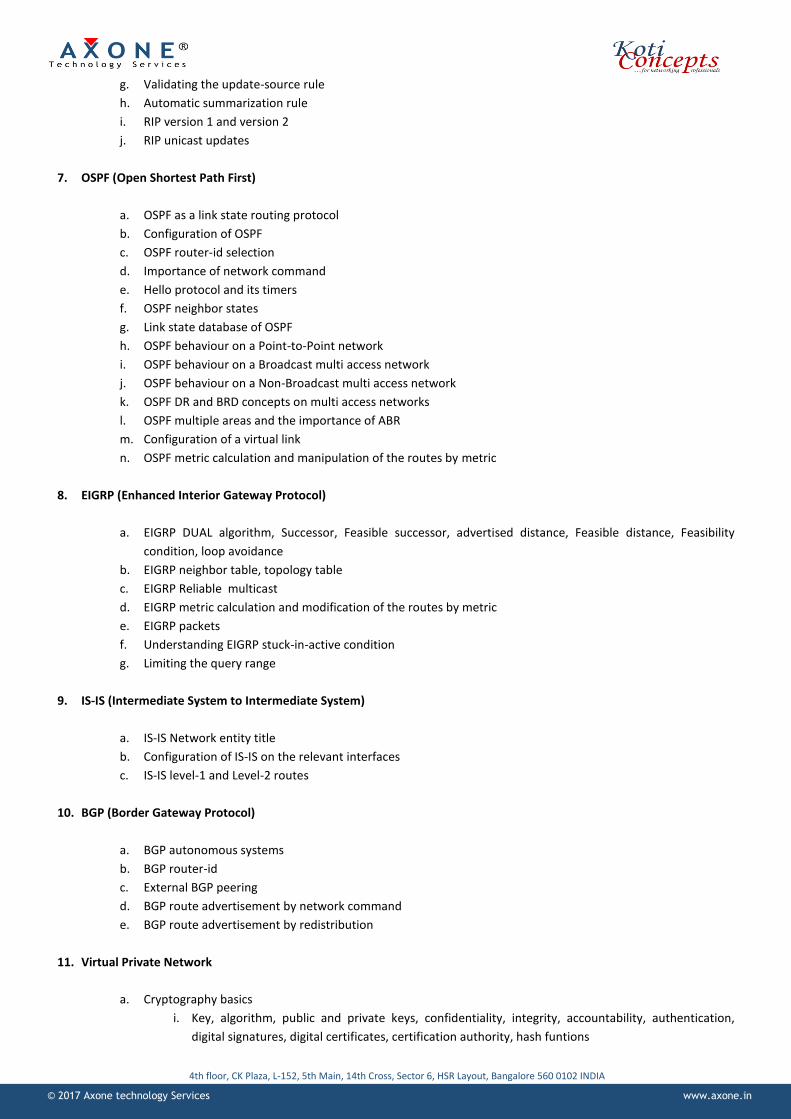
10. BGP (Border Gateway Protocol)
a. BGP autonomous systems
b. BGP router-id
c. External BGP peering
d. BGP route advertisement by network command
e. BGP route advertisement by redistribution
11. Virtual Private Network
a. Cryptography basics
i. Key, algorithm, public and private keys, confidentiality, integrity, accountability, authentication,
digital signatures, digital certificates, certification authority, hash funtions

© 2017 Axone technology Services www.axone.in
4th floor, CK Plaza, L-152, 5th Main, 14th Cross, Sector 6, HSR Layout, Bangalore 560 0102 INDIA
b. IPSec
i. ESP and AH
ii. Transport and tunnel mode
iii. IKE
c. Site to Site IPsec VPN
d. DMVPN
i. Point-to-point GRE tunnels
ii. Multipoint GRE tunnels
iii. NHRP protocol
iv. IPSec over GRE
12. IPv6 tunnelling
a. Tunnelling of IPv6 packets through a IPv4 network
i.
13. MPLS (Multi Protocol Label switching)
a. MPLS v/s IP routing
b. MPLS labels
c. LDP protocol
14. PPPOE
a. Configuration of PPPoE server
b. Configuration of PPPoE client
c. Virtual templates
15. IP SLA (Service Level agreement)
a. Configuration of IP SLA
16. Frame Relay
a. Configuration of a Frame relay switch
b. Fully meshed topology
c. Hub and Spoke topology
d. Hub and Spoke topology with sub interfaces
e. Behaviour of RIP on Frame relay Hub and Sopke topology
f. Behaviour of EIGRP on Frame relay Hub and Sopke topology
g. Behaviour of OSPF on Frame relay Hub and Sopke topology
17. NAT (Network Address Translation)
a. Dynamic NAT
b. Dynamic NAT with overload
c. Static NAT
d. NAT and Access-lists
e. NAT and IPSec VPN
f. NAT and Load balancing
g. NAT and virtual servers
h. NAT and DNS

© 2017 Axone technology Services www.axone.in
4th floor, CK Plaza, L-152, 5th Main, 14th Cross, Sector 6, HSR Layout, Bangalore 560 0102 INDIA
18. Access-Lists
a. Standard access-lists
b. Extended access-lists
19. Redistribution
a. Redistribution between different routing protocols like RIP, EIGRP, OSPF, IS-IS and BGP
b. Redistribution of “connected” and “static” routes
c. Metric issues with redistribution
20. Multicast
a. Multicast addressing scheme
b. Streaming with VLC
c. IGMP messages
d. PIM dense mode
e. Multicast routing and multicast routing tables
21. Switching
a. VLANs and inter-VLAN routing
b. Trunk ports
c. Port aggregation
d. VTP
e. STP
f. HSRP
g. VRRP
h. GLBP
i. Switch security
j. Configuration of Access-lists on a layer-3 switch
k. Configuration of NAT on a layer-3 switch
l. Configuration of routing protocols on a layer-3 switch

© 2017 Axone technology Services www.axone.in
4th floor, CK Plaza, L-152, 5th Main, 14th Cross, Sector 6, HSR Layout, Bangalore 560 0102 INDIA
SAMPLE CASE STUDIES FROM OUR CCNA+ PROGRAM
1. LAB CASE STUDY 18 - IPV4- REDISTRIBUTION BETWEEN RIP, EIGRP, OSPF, IS-IS AND BGP
Objectives This Case study would make the student understand the following concepts
Configuration of Redistribution between RIP, EIGRP, OSPF, IS-IS, BGP and associated issues
Redistribution of “Connected” routes
Case Study Diagram
Task no 1: Preparation of the lab setup
1. Configure the physical topology using Systems, Routers and Switches as shown in the topology diagram
2. Configure Sys10, Sys20, Sys30, Sys40, Sys50, Sys60, Sys70 and Sys80 with the IP addresses as shown in the diagram
3. Configure Sys10, Sys20, Sys30, Sys40, Sys50, Sys60, Sys70 and Sys80 with appropriate default gateway IP addresses as
shown in the diagram
4. Configure the appropriate interfaces on R1, R2, R3, R4, R5, R6, R7, R8, R9 and R10 routers with the IP addresses as
shown in the diagram
5. Bring the line protocol on the relevant interfaces to the “up” state
Task no 2: Verification of reachability between Sys10, Sys20, Sys30, Sys40, Sys50, Sys60, Sys70 and Sys80
1. From Sys10, Ping 30.0.0.10 Are you able to get the reply? Yes _________No______________
2. From Sys10, Ping 40.0.0.10 Are you able to get the reply? Yes _________No______________
3. From Sys10, Ping 50.0.0.10 Are you able to get the reply? Yes _________No______________

© 2017 Axone technology Services www.axone.in
4th floor, CK Plaza, L-152, 5th Main, 14th Cross, Sector 6, HSR Layout, Bangalore 560 0102 INDIA
Task no 3: Configuration of IS-IS protocol on R1, R2, and R3
1. Configure IS-IS on R1, R2 and R3 with the following parameters
a. Choose the Network Entity Title as 51.0000.0000.0001.00 for R1
b. Choose the Network Entity Title as 51.0000.0000.0002.00 for R2
c. Choose the Network Entity Title as 51.0000.0000.0003.00 for R3
d. Enable IS-IS for IPv4 on the relevant interfaces
e. Do not enable IS-IS protocol process on F0/0 interface of R1
Task no 4: Configuration of RIP protocol on R3, R4, and R5
1. Configure R3, R4 and R5 with RIP protocol. Enable RIP protocol process on the relevant interfaces. Do not enable
RIP protocol process on F0/0 interface of R5
Task no 5: Configuration of EIGRP 100 protocol on R6, R7, and R8
1. Configure R6, R7, and R8 with EIGRP protocol and keep them in autonomous system 200. Enable EIGRP
protocol process on the relevant interfaces of the routers. Do not enable EIGRP protocol process on F0/0
interface of R8
Task no 6: Configuration of OSPF protocol on R6, R9, and R10
1. Configure OSPF on R6, R9 and R10 with the following parameters
a. Choose the process id as 10
b. Choose Router-id for R6 as 6.6.6.6
c. Choose Router-id for R9 as 9.9.9.9
d. Choose Router-id for R10 as 10.10.10.10
e. Choose appropriate wild card mask for the network command
f. Do not enable OSPF protocol process on F0/0 interface of R10
g. Keep all the OSPF interfaces in Area 1
Task no 7: Understanding the routing table entries of R1, R5, R8, R3, R6 and R10 before redistribution
1. Is there a route for following network in the routing table of R1
a. 20.0.0.0/8, Yes______No______If Yes, what is the source of the route? Ans:______
b. 21.0.0.0/8, Yes______No______If Yes, what is the source of the route? Ans:______
c. 22.0.0.0/8, Yes______No______If Yes, what is the source of the route? Ans:______
2. Is there a route for following network in the routing table of R5
a. 20.0.0.0/8, Yes______No______If Yes, what is the source of the route? Ans:______
b. 21.0.0.0/8, Yes______No______If Yes, what is the source of the route? Ans:______
c. 22.0.0.0/8, Yes______No______If Yes, what is the source of the route? Ans:______
a. 21.0.0.0/8, Yes______No______If Yes, what is the source of the route? Ans:______
b. 22.0.0.0/8, Yes______No______If Yes, what is the source of the route? Ans:______
Task no 22
1. From Sys10, Ping 30.0.0.10 Are you able to get the reply? Yes _________No______________
2. From Sys10, Ping 40.0.0.10 Are you able to get the reply? Yes _________No______________
3. From Sys10, Ping 50.0.0.10 Are you able to get the reply? Yes _________No______________

© 2017 Axone technology Services www.axone.in
4th floor, CK Plaza, L-152, 5th Main, 14th Cross, Sector 6, HSR Layout, Bangalore 560 0102 INDIA
1. LAB CASE STUDY 37 - EIGRP METRIC CALCULATION
In this case study the students work with 12 routers and a layer 3 switch to understand the following concepts
a. Configuration of EIGRP
b. EIGRP metric calculation
c. EIGRP metric manipulation to get the desired routes in the routing tables

© 2017 Axone technology Services www.axone.in
4th floor, CK Plaza, L-152, 5th Main, 14th Cross, Sector 6, HSR Layout, Bangalore 560 0102 INDIA
2. LAB CASE STUDY 43
In this case study the students work with 9 servers, 10 workstations, 6 switches and 7 routers to understand the
following concepts
a. Configuration of Vlans and inter-Vlan routing
b. Configuration of trunk ports
c. Configuration of HSRP
d. Configuration of manual load balancing with HSRP
e. Configuration of host and MX records on the DNS server
f. Configuration of routing with EIGRP protocol
g. Configuration of Dynamic NAT
h. Configuration of static NAT
i. Configuration of access-lists

© 2017 Axone technology Services www.axone.in
4th floor, CK Plaza, L-152, 5th Main, 14th Cross, Sector 6, HSR Layout, Bangalore 560 0102 INDIA
3. LAB CASE STUDY 21
In this case study the students work with 25 routers to understand the following concepts
a. Configuration of static and default routes
b. Configuration of RIP
c. Configuration of EIGRP
d. Configuration of OSPF
e. Configuration of IS-IS
f. Configuration of BGP
g. Redistribution of routes between RIP, EIGRP, OSPF, IS-IS and BGP
h. Redistribution of connected and static routes
i. Troubleshooting of the issues with redistribution of routes from one routing protocol to another

© 2017 Axone technology Services www.axone.in
4th floor, CK Plaza, L-152, 5th Main, 14th Cross, Sector 6, HSR Layout, Bangalore 560 0102 INDIA
THEORY TEST SAMPLES
Test no 5
Test objectives:
1. To test the student’s ability to design IP addressing with subnets as per the requirement.
2. To test the students ability to configure static routing to enable the hosts in different subnets with variable length
subnet mask (VLSM) reachable.
3. To test the student’s ability to configure Dynamic Nat.
4. To test the student’s ability to configure Dynamic Nat with overload.
5. To test the student’s ability to configure static Nat.
6. To test the student understanding of the packet structures and network traffic patterns.
7. To test the student’s ability to configure proper access-lists to allow desired network traffic inside out the secured
network.
8. To test the students ability to install and configure the hosts with different operating systems and applications.
9. To test the students ability to install and configure the applications with different services.
10. To test the students ability to configure static routing.
Case study Diagram:
Task no 1 - Calculate the subnets and identify IP addresses for the hosts and routers as shown in the diagram.
1. Write down the network ID and subnet mask of the subnets.
NETWORK NETWORK ID SUBNET MASK
SB-HoA
SB-HoB
SB-HoC
SB-HO-DMZ
P-T-P (RA-RB)
KC-HoA
© 2017 Axone technology Services www.axone.in
4th floor, CK Plaza, L-152, 5th Main, 14th Cross, Sector 6, HSR Layout, Bangalore 560 0102 INDIA
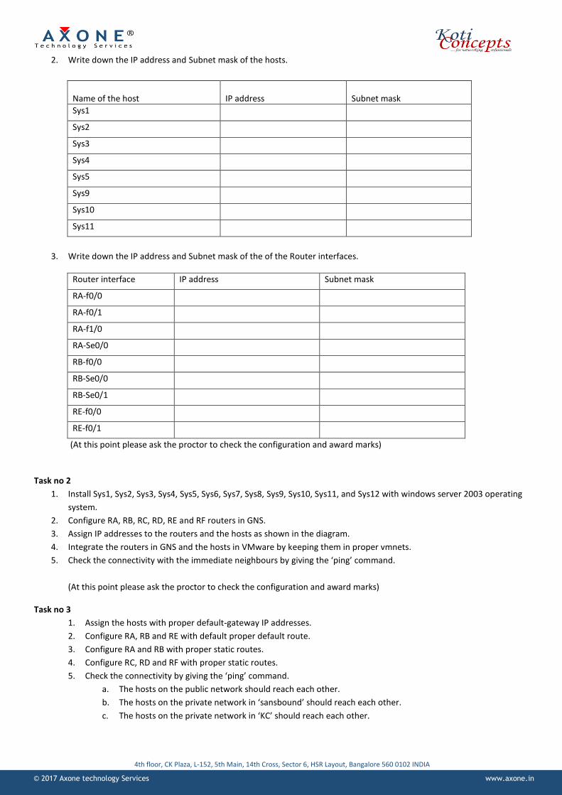
2. Write down the IP address and Subnet mask of the hosts.
Name of the host
IP address
Subnet mask
Sys1
Sys2
Sys3
Sys4
Sys5
Sys9
Sys10
Sys11
3. Write down the IP address and Subnet mask of the of the Router interfaces.
Router interface IP address Subnet mask
RA-f0/0
RA-f0/1
RA-f1/0
RA-Se0/0
RB-f0/0
RB-Se0/0
RB-Se0/1
RE-f0/0
RE-f0/1
(At this point please ask the proctor to check the configuration and award marks)
Task no 2
1. Install Sys1, Sys2, Sys3, Sys4, Sys5, Sys6, Sys7, Sys8, Sys9, Sys10, Sys11, and Sys12 with windows server 2003 operating
system.
2. Configure RA, RB, RC, RD, RE and RF routers in GNS.
3. Assign IP addresses to the routers and the hosts as shown in the diagram.
4. Integrate the routers in GNS and the hosts in VMware by keeping them in proper vmnets.
5. Check the connectivity with the immediate neighbours by giving the ‘ping’ command.
(At this point please ask the proctor to check the configuration and award marks)
Task no 3
1. Assign the hosts with proper default-gateway IP addresses.
2. Configure RA, RB and RE with default proper default route.
3. Configure RA and RB with proper static routes.
4. Configure RC, RD and RF with proper static routes.
5. Check the connectivity by giving the ‘ping’ command.
a. The hosts on the public network should reach each other.
b. The hosts on the private network in ‘sansbound’ should reach each other.
c. The hosts on the private network in ‘KC’ should reach each other.

© 2017 Axone technology Services www.axone.in
4th floor, CK Plaza, L-152, 5th Main, 14th Cross, Sector 6, HSR Layout, Bangalore 560 0102 INDIA
(At this point please ask the proctor to check the configuration and award marks)
LAB TEST SAMPLES
Test no 11
Task no 1
Configure R16 as the Frame Relay switch between the head office and the branch offices 1,2 and 3 with the PVCs as shown in
the diagram.
Configure Frame Relay in Hub and Spoke topology with subinterfaces between R1, R4, R5 and R6 as shown in the diagram.
Configure subinterfaces on the head office router (R1) as required and associate them with appropriate PVCs.
Ensure that the line protocol between the router above is in the ‘UP’ state.

© 2017 Axone technology Services www.axone.in
4th floor, CK Plaza, L-152, 5th Main, 14th Cross, Sector 6, HSR Layout, Bangalore 560 0102 INDIA
Check the connectivity by using the Ping command and solve problems if any.
Task no 2
Enable PPP with authentication between R1 and R3. Authentication should be done by CHAP protocol with the password,
‘disco’. Ensure that the line protocol is in the ‘UP’ state.
Enable PPP with authentication between R1 and R2. Authentication should be done by PAP protocol with the password, ‘jazz’.
Ensure that the line protocol is in the ‘UP’ state.
Enable HDLC between R2 and R3. Ensure that the line protocol is in the ‘UP’ state.
Task no 3
Assign IP addresses to the e0/0 interface of R4 and R5 routers of the branch offices 1 and 2 by subnetting according to the
criteria shown in the diagram. The network ID is 10.0.0.0
Task no 4
Assign IP addresses to all the routers and systems as shown in the diagram and ensure that the line protocol is in the ‘UP’
state.
Assign the appropriate default gateway IP addresses to the systems as shown in the diagram.
Task no 5
Assign IP addresses to Sys1, Sys2, Sys3, as shown in the diagram.
Configure VLANS 1 and 2 on the switches and enable inter VLAN routing.
Task no 6
Enable RIP protocol on R1, R2, R3, R4, R5 and R6 with appropriate version.
Solve the problems of routing and ensure that all the networks are reachable that are connected to the above 6 routers.
Task no 7
Assign IPv6 addresses to the routers R3, R6, Sys6 and Sys7 as shown in the diagram.
Configure IPv6 to IPv4 tunneling so that the systems Sys6 and Sys7 could talk to each other.
Task no 8
Configure OSPF on R7, R9, R8, R10, R15, R11 with the process ID 10.
Enable OSPF on the interfaces and keep them in the appropriate areas as shown in the diagram.
Configure ‘Virtual links’ wherever required.
Task no 9
Configure EIGRP 100, EIGRP 200 and EIGRP 300 on the concerned routers as shown in the diagram.
Enable redistribution between the EIGRP routers in different autonomous systems as required.
Task no 10
Enable redistribution between OSPF and EIGRP so that all the networks are reachable.

© 2017 Axone technology Services www.axone.in
4th floor, CK Plaza, L-152, 5th Main, 14th Cross, Sector 6, HSR Layout, Bangalore 560 0102 INDIA
Task no 11
Configure NAT on R1 router so that all the systems and routers in the enterprise could access the Internet using the valid IP
address assigned to R1.
Configure Static NAT on R1 so that the users on the Internet could access Sys1 with the static IP address 20.0.0.10
Task no 12
Install and configure a website www.yahoo.com on Sys5.
Install and configure an FTP site, ‘FTP.Redbooks.IBM.com’ on Sys8. Create a file by name ‘Redbook.txt’ and store it in the FTP
site.
Install and configure DNS service on Sys4 to resolve the names, ‘www.yahoo.com’, ‘FTP.Redbooks.IBM.com’ and
‘www.sansbound.edu’
Install and configure a website www.axone.in on Sys1.
Tasks no 13
Configure Access-lists on R1 so that the systems in the VLAN 2 could access any website and FTP site on the Internet, and bind
it to the appropriate interface.
Configure Access-lists on R1 so that the systems on the Internet could access ‘Sys1’ for HTTP service.