Bacillus Spores from Environmental Surfaces
202
EPA 600/R-13/137 | August 2013 | www.epa.gov/ord Evaluation of Vacuum-based Sampling Devices for Collection of Bacillus Spores from Environmental Surfaces Assessment and Evaluation Report Office of Research and Development National Homeland Security Research Center
Transcript of Bacillus Spores from Environmental Surfaces
EPA 600/R-13/137 | August 2013 | www.epa.gov/ord
Evaluation of Vacuum-based Sampling Devices for Collection of Bacillus Spores from Environmental Surfaces
Assessment and Evaluation Report
Offi ce of Research and DevelopmentNational Homeland Security Research Center

ii
EPA 600-R-13-137
Evaluation of Vacuum-based Sampling Devices for Collection of Bacillus spores from Environmental Surfaces
Assessment and Evaluation Report
National Homeland Security Research Center
Office of Research and Development
U.S. Environmental Protection Agency
Research Triangle Park, NC 27711

iii
Disclaimer
The United States Environmental Protection Agency (EPA), through its Office of Research and Development’s National Homeland Security Research Center, managed this investigation through EP-C-09-027 WA 2-10 and 3-10 with ARCADIS U.S., Inc. The effort was funded through an interagency agreement (RW-75-92345701) with the US Centers for Disease Control and Prevention (CDC). This report has been peer and administratively reviewed and has been approved for publication as an EPA document. It does not necessarily reflect the views of the EPA. No official endorsement should be inferred. This report includes photographs of commercially available products. The photographs are included for purposes of illustration only and are not intended to imply that EPA approves or endorses the product or its manufacturer. The EPA does not endorse the purchase or sale of any commercial products or services.
Questions concerning this document or its application should be addressed to:
M. Worth Calfee, Ph.D. Decontamination and Consequence Management Division National Homeland Security Research Center U.S. Environmental Protection Agency (MD-E343-06) Office of Research and Development 109 T.W. Alexander Drive Research Triangle Park, NC 27711 Phone: 919-541-7600 Fax: 919-541-0496 E-mail: calfee.worth@ epa.gov

iv
Acknowledgments
This effort was managed by the principal investigator from the National Homeland Security Research Center (NHSRC) within EPA’s Office of Research and Development. Laura Rose (CDC’s Clinical and Environmental Laboratory Branch, Division of Healthcare Quality Promotion (DHQP) within the National Center for Emerging and Zoonotic Infectious Diseases (NCEZID) and Dino Mattorano (EPA’s Chemical, Biological, Radiological, and Nuclear Consequence Management Advisory Team (CBRN CMAT) within the Office of Emergency Management (OEM) provided critical inputs into this investigation. Additionally, the efforts of Stephen Morse and Angela Weber (CDC’s Office of Environmental Microbiology, Division of Foodborne, Waterborne, and Environmental Diseases (DFWED), within the NCEZID are gratefully recognized.
The authors would like to thank the peer reviewers for their significant contributions. Specifically, the efforts of Lisa Delaney (National Institute for Occupational Safety and Health (NIOSH)), Matt Arduino (CDC), and Erin Silvestri (EPA) are recognized.

v
Table of Contents
Disclaimer ............................................................................................................................................. iii
Acknowledgments ................................................................................................................................ iv
Table of Contents .................................................................................................................................. v
List of Appendices............................................................................................................................... vii
List of Tables ...................................................................................................................................... viii
List of Acronyms and Abbreviations .................................................................................................... x
Executive Summary............................................................................................................................. xii
1 Introduction .................................................................................................................................... 1
1.1 Process ..................................................................................................................................... 1
1.2 Project Objectives...................................................................................................................... 1
1.3 Experimental Approach ............................................................................................................. 2
1.3.1 Vacuum-based Sampling Device Evaluation Tests – Phase 1 ............................................ 2
1.3.2 HVAC Inoculation Tests – Phase 2 .................................................................................... 2
1.3.3 HVAC Sampling Tests – Phase 2....................................................................................... 2
1.3.4 Inoculum Variability and Level Tests – Phase 3.................................................................. 3
1.3.5 Linearity Recovery Tests and Laboratory Variability Tests – Phase 3 ................................. 3
1.4 Definition of Sampling Efficiency ................................................................................................ 3
2 Materials and Methods ................................................................................................................... 4
2.1 Test Materials and Deposition .................................................................................................... 4
2.1.1 Coupon Preparation........................................................................................................... 4
2.1.2 Bacillus Spore Preparation................................................................................................. 6
2.1.3 Coupon Inoculation ............................................................................................................ 6
2.2 Test Matrix ................................................................................................................................ 9
2.3 Sampling and Analytical Procedures ........................................................................................ 11
2.3.1 Swab Sampling................................................................................................................ 11
2.3.2 Polyester-Rayon Blend (PRB) Wipe Sampling ................................................................. 11
2.3.3 Sponge-wipe Sampling .................................................................................................... 12
2.3.4 Vacuum Sock Sampling and Analysis .............................................................................. 12
2.3.5 37 mm MCE and 37 mm PTFE Sampling ......................................................................... 13
2.3.6 Trace Evidence Filter Sampling ....................................................................................... 14
2.3.7 Operational Assessment .................................................................................................. 14
2.3.8 HVAC filter extraction....................................................................................................... 15

vi
2.3.9 Quartz extraction ............................................................................................................. 15
2.3.10 Direct Extraction of Stainless Steel .................................................................................. 15
2.4 Sampling Strategy ................................................................................................................... 16
2.4.1 Sampling/Monitoring Points ............................................................................................. 16
2.5 Sampling Handling and Custody .............................................................................................. 18
2.5.1 Preventing Cross-contamination during Coupon Preparation ............................................ 18
2.5.2 Preventing Cross-contamination during Sampling ............................................................ 18
2.5.3 Preventing Cross-contamination during Analysis .............................................................. 19
2.5.4 Sample Containers .......................................................................................................... 19
2.5.5 Sample Identification ....................................................................................................... 19
2.5.6 Information Recorded by Field Personnel......................................................................... 20
2.5.7 Sample Preservation ....................................................................................................... 20
2.5.8 Sample Holding Times ..................................................................................................... 20
2.5.9 Sample Custody .............................................................................................................. 20
2.5.10 Sample Archiving ............................................................................................................. 21
2.6 Statistical Analysis Methods..................................................................................................... 21
3 Results and Discussion ............................................................................................................... 22
3.1 Phase 1 ................................................................................................................................... 22
3.1.1 Results of Statistical Analyses ......................................................................................... 24
3.1.2 Operational Parameters ................................................................................................... 24
3.1.2.1 Sampling Time and Ease ......................................................................................... 24
3.1.2.2 Analysis Time and Ease ........................................................................................... 25
3.1.2.3 Cost ......................................................................................................................... 25
3.2 Phase 2 ................................................................................................................................... 26
3.3 Phase 3 ................................................................................................................................... 30
4 Quality Assurance ........................................................................................................................ 35
4.1 Sampling, Monitoring, and Analysis Equipment Calibration ...................................................... 35
4.2 Data Quality ............................................................................................................................ 36
4.3 QA/QC Checks ........................................................................................................................ 36
4.4 Acceptance Criteria for Critical Measurements ......................................................................... 38
4.5 Data Quality Audits .................................................................................................................. 39
4.6 QA/QC Reporting .................................................................................................................... 39

vii
5 Summary ....................................................................................................................................... 40
5.1 Phase 1 ................................................................................................................................... 40
5.2 Phase 2 ................................................................................................................................... 40
5.3 Phase 3 ................................................................................................................................... 40
5.4 Lessons Learned and Application of Vacuum-based Methods to Field Use .............................. 40
5.5 Future Research ...................................................................................................................... 42
References ........................................................................................................................................... 43
List of Appendices
Appendix A Miscellaneous Operating Procedures (MOPs) included as a separate document
viii
List of Figures
Figure 2-1. Carpet Coupon .................................................................................................................. 4
Figure 2-2. Upholstery Coupon ............................................................................................................ 5
Figure 2-3. Concrete Coupon .............................................................................................................. 5
Figure 2-4. Schematic of Deposition Apparatus for Inoculation under Flow Conditions ......................... 8
Figure 2-5. Vacuum Sock Kit and Individual Sock. ............................................................................. 13
Figure 2-6. Filter (37 mm) Cassette with Nozzle and Tubing .............................................................. 14
Figure 2-7. 3M® Trace Evidence Filter (TEF) Vacuum-based Sampling Device .................................. 15
Figure 3-1. Recovery from Materials for each Vacuum Method. . ...................................................... 22
Figure 3-2. Relative Recovery – Data presented as mean relative recovery (RR) ............................... 23
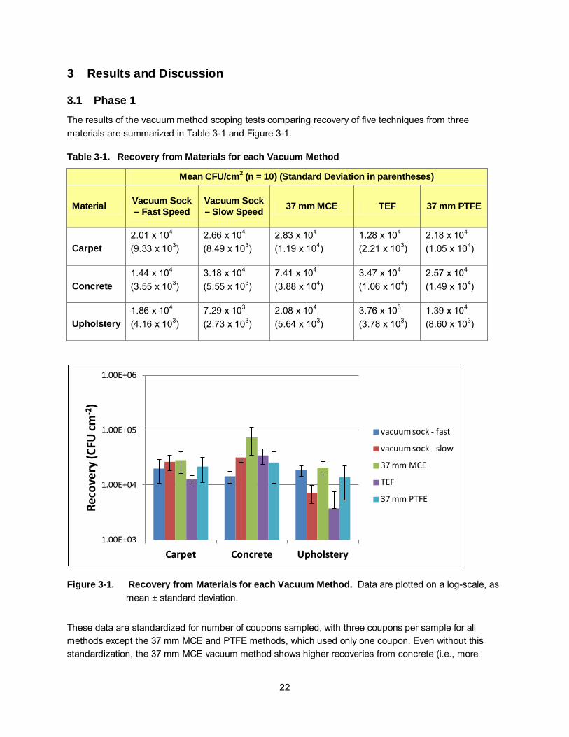
Figure 3-3. Recovery from HVAC Filters Using 5 Sampling Methods – Test HI2................................. 27
Figure 3-4. Recovery from Mechanical MERV 8 Filter – Test HS ....................................................... 28
Figure 3-5. Recovery from Electrostatic HVAC Filter – Test HS.......................................................... 29
Figure 3-6. Recovery from Stainless Coupons during INOC Series Tests........................................... 31
Figure 3-7. Mean CFU/Sample from Linear Recovery (LR) Test......................................................... 32
Figure 3-8. Laboratory Variability for Two Vacuum Methods - Test LV ............................................... 34
List of Tables
Table 2-1. Phase 1Test Matrix ............................................................................................................ 9
Table 2-2. Phase 2 Test Matrix ........................................................................................................ 10
Table 2-3. Phase 3 Test Matrix ......................................................................................................... 10
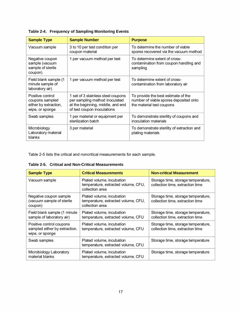
Table 2-4. Frequency of Sampling Monitoring Events ....................................................................... 17
Table 2-5. Critical and Non-Critical Measurements ........................................................................... 17
Table 3-1. Recovery from Materials for each Vacuum Method .......................................................... 22
Table 3-2. Relative Recoveries from all Devices and Material Surface Types ................................... 23
Table 3-3. Average Recovery from HVAC Filter Extraction – Test HI1 .............................................. 26
Table 3-4. Recovery from HVAC filters – Test HI2 ............................................................................ 26
Table 3-5. HVAC Vacuuming Recovery – Test HS............................................................................ 27
Table 3-6. Student’s t-test values from Electrostatic filters ................................................................ 28
Table 3-7. Mean Recovery from Stainless Steel Coupons (n = 3), Phase 2 Tests ............................. 30
Table 3-8. ANOVA – Comparison of the Three Stainless Steel Recovery Methods within each Phase 2 Test Run (n = 3) ................................................................................................. 30

ix
Table 3-9. Mean Recoveries from Stainless Steel using the Sponge-wipe Method - Test INOC (n = 10)............................................................................................................................ 30
Table 3-10. Mean Recoveries (CFU/sample) from Test LR (n=5) ........................................................ 31
Table 3-11. Percent Relative Recovery of Vacuum Devices (Test LR) (n = 5) ..................................... 32
Table 3-12. Relative Recovery of Vacuum Methods to Sponge-Wipe – Test LR (n=5)......................... 33
Table 3-13. Laboratory Variability for Two Vacuum Methods (Test LV) ............................................... 34
Table 4-1. Sampling and Monitoring Equipment Calibration Frequency ............................................. 35
Table 4-2. QA/QC Sample Acceptance Criteria ................................................................................ 37
Table 4-3. Critical Measurement Acceptance Criteria........................................................................ 38
Table 5-1. Summary of Advantages and Disadvantages of Each Vacuum-Based Sampling Method. ........................................................................................................................... 41

x
List of Acronyms and Abbreviations
%Cv Percent Coefficient of Variation ADA aerosol deposition apparatus ANOVA Analysis of Variance APPCD Air Pollution Prevention and Control Division ATCC American Type Culture Collection CBRN Chemical, Biological, Radiological, and Nuclear CDC Centers for Disease Control and Prevention CFM cubic feet per minute CFU colony forming unit(s) CM critical measurement cm2 square centimeter CMAT Consequence Management Advisory Team COC chain of custody DCMD Decontamination and Consequence Management Division DFWED Division of Foodborne, Waterborne, and Environmental Diseases DHQP Division of Healthcare Quality Promotion DPG Dugway Proving Ground DQI Data Quality Indicator DQO Data Quality Objective ECBC Edgewood Chemical Biological Center EPA U. S. Environmental Protection Agency EtO ethylene oxide ft2 square feet HAZMAT Hazardous Materials H2O2 hydrogen peroxide HVAC heating, ventilation, and air conditioning ID Internal Diameter in. inch(es) INL Idaho National Laboratory INOC Inoculation ISO International Organization for Standardization L liter(s) L min-1 liters per minute LR Linear Range LV Laboratory Variability MCE Mixed Cellulose Ester MDI metered dose inhaler MERV Minimum Efficiency Reporting Value MOP Miscellaneous Operating Procedure NCEZID National Center for Emerging and Zoonotic Infectious Diseases NHSRC National Homeland Security Research Center NIST National Institute of Standards and Technology OEM Office of Emergency Management PBS Phosphate Buffered Saline

xi
PBST Phosphate Buffered Saline with 0.05% TWEEN® 20 PRB Polyester-Rayon Blend PTFE Polytetrafluoroethylene PVC Polyvinylchloride rpm rotations per minute RR% Relative Recovery Percentage RSD Relative Standard Deviation QA Quality Assurance QAPP Quality Assurance Project Plan QC Quality Control SCFM standard cubic feet per minute SOP Standard Operating Procedure STS Sodium Thiosulfate TEF Trace Evidence Filter VHP Vaporous Hydrogen Peroxide WAM Work Assignment Manager

xii
Executive Summary
The existing surface sampling strategy for a biological incident involving B. anthracis spores necessitates the use of various methods depending on the surface type. Currently-recommended surface sample collection methods include pre-moistened wipes (for smooth nonporous surfaces), vacuuming (for rough and porous surfaces), and wet swabs (for small and/or hard-to-sample areas such as keyboards). The currently-used vacuum-based method utilizes woven collection socks attached to a cardboard nozzle. Some criticisms of the current method are that the vacuum socks often come from the manufacturer with visible holes in the sock seams, the method is vulnerable to cross-contamination between samples, the socks are constructed of materials with large pore-sizes (> 1µm), and the filters are cumbersome for laboratory handling and extraction during analysis. This project comparatively evaluated the vacuum sock and two additional vacuum-based collection devices (37 mm filter cassette and 3M™ Trace Evidence Filter) for their sampling efficacy. The 37 mm filter cassette was evaluated with mixed cellulose ester (MCE) filters or polytetrafluoroethylene (PTFE) filters installed, each was considered a unique device. These data were generated so appropriate sampling devices could be selected following a B. anthracis incident.
A known quantity of Bacillus atrophaeus (B. anthracis surrogate) spores was aerosolized and deposited onto large coupons (1 square foot (ft2)) of various materials common to the built environment, including carpet, upholstery, unpainted (smooth finish) concrete, and two types (electrostatic and mechanical) of heating, ventilation and air conditioning (HVAC) filters. Coupons were then subjected to vacuum-based sampling and sample analysis according to protocols developed jointly by the US Centers for Disease Control and Prevention (CDC) and US Environmental Protection Agency (EPA). Recovery was determined for each sampling method according to culture-based microbiological assays following physical extraction methods developed by the CDC.
Phase 1 of this study included the evaluation of vacuum-based sampling devices. These tests were conducted with four different devices and one sampling variation (fast or slow sampling rate at which the device passed over the sampled surface) for the vacuum sock. Samples were collected from three porous surface types for each device, each with ten replicate samples. Vacuum and wipe samples were also collected from stainless steel coupons as a method to standardize results collected on different days and with different inoculation devices.
For carpet, the slow vacuum sock method had the highest spore recovery. For concrete, the 37 mm MCE had the highest spore recovery. For upholstery, the 37 mm MCE had the highest spore recovery. The vacuum sock method afforded more ease of use and may therefore be more desirable for larger sample areas. However, on concrete and upholstery, the 37 mm MCE filter method demonstrated higher recoveries per unit area than did the vacuum sock device. The significance of these differences was dependent upon the statistical test performed. There are advantages and disadvantages of each device. Changing the speed at which the vacuum sock sampling device passed over the surface did not necessarily improve the recovery of spores from the porous surfaces tested.
During Phase 2, collection of B. atrophaeus spores from contaminated HVAC filters with two vacuum-based devices (devices with the highest recoveries from Phase 1, vacuum sock (slow rate) and 37 mm MCE cassette) was compared to sampling by extractive methods (removing a portion of the filter and extracting spores from the filter matrix). Contamination of HVAC filters during a biological incident, unlike

xiii
most surfaces, is expected to occur under flow conditions, with HVAC blowers pulling spores to the interior of the filter. A method was developed which successfully deposited spores on (and within) HVAC filters under flow conditions.
Two types of clean (new) HVAC filters (electrostatic and mechanical) were inoculated similarly to Phase 1, yet under flow conditions. The contaminated surfaces were then evaluated using three methods: direct extraction from excised sections of the HVAC filter, vacuum sock sampling, and 37 mm MCE filter vacuum sampling. In addition, the magnitude and variability of the inoculating metered dose inhaler (MDI) was evaluated with three methods: sponge-wipe sampling of stainless steel coupons, pre-moistened (polyester-rayon blend, PRB) wipe sampling of stainless steel coupons, and direct extraction of stainless steel coupons.
Three methods (two vacuum methods and one extractive) of sampling HVAC filters performed reliably on mechanical and electrostatic filters. The data suggest that extractive methods are more efficient than vacuum-based recovery methods for electrostatic filters, but not for mechanical filters. When comparing the two vacuum-based methods, the vacuum sock method provided higher recoveries than the 37 mm MCE method from electrostatic filters, but there was no statistical difference in recoveries from the electrostatic filters. Vacuum-based methods may be more applicable to HVAC filter media that are not easily sectioned.
Phase 2 data also suggested there was no statistical difference between direct extraction, sponge-wipes, or pre-moistened PRB wipes for recovery (inoculum magnitude) from stainless steel coupons. Mean variability (%Cv) was also similar across all methods, at 28%, 22%, and 20% for the extraction-based method, sponge-wipe method, and PRB wipe method.
During Phase 3, Inoculum Variability and Level Tests (INOCs) were conducted to determine the repeatability and magnitude of inoculation from the MDI/ aerosol deposition apparatus (ADA) dosing method. Three inoculum levels (corresponding to three concentrations of spores within MDIs - 104, 106, 107 spores per coupon) were used to dose up to ten replicate stainless steel coupons. The MDI inoculation method was demonstrated over a broad range of surface contamination concentrations, from 1 to 1 × 10⁴ CFU/square centimeter (cm2).
Also during Phase 3, Linearity Recovery (LR) Tests and Laboratory Variability (LV) Tests were conducted to determine: (1) if vacuum-based method recoveries were linear over a range of concentrations; and (2) if recoveries varied significantly between two different technicians processing (extracting and plating) the samples. During these tests, carpet coupons were sampled using two chosen vacuum sampling methods: vacuum sock (slow) and 37 mm MCE. Following collection, all samples were extracted and plated by two technicians. All samples for both devices and all three inoculum levels were collected on a single day so that comparisons could be made across devices, inoculum levels, and technicians. One technician operated the vacuum-based collection device for all samples. Recoveries were compared between the two technicians to determine if technician-induced variability was significant. The linearity of recoveries for each device was determined graphically by plotting recovery versus the targeted inoculum. The two vacuum methods were demonstrated effective for all inoculum concentrations. Compared to sponge-wipes (from stainless steel), the vacuum sock method recovered between 3% and 22% CFU, while the 37 mm MCE method recovered between 4% and 140% CFU from carpet samples. Relative recoveries greater than 100% were possible because these values were determined by dividing vacuum method recovery by wipe-based recovery from stainless steel. Greater than 100% relative recovery
xiv
indicated that the vacuum method out-performed the wipe method. Finally, the extraction procedures for both vacuum methods were evaluated by two independent laboratory technicians with no statistical difference in the two recoveries.
These data were collected to aid in sampling device and strategy selection following a biological contamination incident.

1
1 Introduction
The U.S. Environmental Protection Agency (EPA) conducted a study, in collaboration with the Centers for Disease Control and Prevention (CDC), to evaluate several vacuum-based sampling devices for collection of biological agent from environmental surfaces. Methods for detection and characterization of biological agent on surfaces following a bioterrorism incident include the use of swabs, wipes, and vacuum. Vacuum-based methods are preferred when sampling porous surfaces. Currently, there are no vacuum-based methods validated for collection of Bacillus anthracis spores. Further, multiple vacuum-based devices, sample collection methods, and sample extraction methods were utilized to characterize the extent of contamination following the 2001 anthrax incidents. Recently, some work has been conducted to characterize the performance of vacuum-based surface sampling devices when used to collect Bacillus spores [1-3]. However, significant gaps remain in our understanding of vacuum-based sampler performance, efficiencies, ease of use, and applicability to various material surface types. The current study was conducted to generate data that could be used to inform selection of appropriate sampling methodologies following a B. anthracis incident. Scientifically tested sampling methods will provide increased confidence in the ability to characterize contamination following such an incident.
1.1 Process Consistent with previous sampling studies [1], spores of Bacillus atrophaeus (formerly known as Bacillus globigii or Bacillus subtilis var. niger) served as surrogates for Bacillus anthracis spores. Collection of B. atrophaeus spores from multiple surface types was evaluated with four vacuum-based sampling devices. In addition, collection of biological agent from contaminated heating, ventilation, and air conditioning (HVAC) filters with the two top-performing vacuum-based devices was compared to sampling by destructive methods (removing a portion of the filter and extracting spores directly from the filter matrix).
A known quantity of aerosolized dry B.atrophaeus spores was gravitationally deposited onto large coupons (35.6 cm x 35.6 cm) of various materials common to the built environment, which included carpet, upholstery, unpainted (smooth finish) concrete, and two types of HVAC filters. The coupons were then subjected to vacuum-based sampling according to protocols developed jointly by the CDC and EPA. Recovery was determined for each sampling method according to culture-based microbiological assays following physical extraction methods developed by the CDC. All test parameters, such as coupon materials and sizes, sampling methods, and methods of extraction and analysis were determined by agreement among participating experts from EPA and the CDC.
1.2 Project Objectives The objective of this project was to evaluate four currently-available vacuum-based devices for their ability to recover Bacillus spores from environmental surfaces. Performance (relative recovery) of the devices was compared to recoveries from pre-moistened gauze wipes, used to sample reference stainless steel coupons that were inoculated at the same time as the test coupons. Evaluation of operational parameters included time required for sample collection, the physical impact on the sampling team during collection, time required for sample analysis, and the cost of media and analysis equipment and supplies. Another objective of this study was to evaluate vacuum-based sampling of contaminated HVAC filters to that of extraction-based methods.

2
1.3 Experimental Approach
The experimental approaches that were used to meet the objectives of this project are:
• Use of controlled chambers, standardized sections and spore inoculums.
• Inoculation of material coupons via aerosol deposition of bacterial spores.
• Quantitative assessment of spore recoveries with each device, by sampling representative
sections of materials and then extraction of sampling media to recover collected spores
(enumerated and reported as colony forming units (CFU)).
• Use of reference stainless steel coupons to quantify and standardize results for cross-comparison
of tests.
• Documentation of operational considerations (e.g., cross-contamination, procedural time, impacts
on materials and personnel).
All testing was conducted at EPA’s Research Triangle Park, NC, campus.
1.3.1 Vacuum-based Sampling Device Evaluation Tests – Phase 1
The Vacuum-based Sampling Device Evaluation Tests were conducted with four different device types and one sampling variation (sampling speed) for one device type (Table 2-1). Samples were collected from three surface types (carpet, upholstery, and concrete) for each device with ten replicate samples. Pre-moistened polyester rayon blend (PRB) wipe samples were also collected from reference stainless steel coupons as a method to standardize results collected on different days and with different inoculation devices. The foundation for this test matrix was described in the Quality Assurance Project Plan (QAPP) entitled, “Evaluation of Vacuum-based Sampling Devices for Collection of Biological Agent (Decontamination and Consequence Management Division (DCMD) 3.60)” (available upon request).
1.3.2 HVAC Inoculation Tests – Phase 2
HVAC Inoculation (HI) Tests were conducted to determine the best inoculation method for HVAC filters. Contamination of HVAC filters during a biological incident, unlike most surfaces, is expected to occur under flow conditions, with HVAC blowers pulling spores to the interior of the filter. Also, the porous nature of the substrate presents challenges to even the settling-based aerosol inoculation. For this reason, a modified version of the method developed by Calfee et al., 2013, for depositing aerosolized spores on material surfaces, was utilized for this substrate. These tests were conducted to verify that the inoculation target (quantity of spores) could be achieved without excessive variability.
1.3.3 HVAC Sampling Tests – Phase 2
HVAC Sampling (HS) Tests were conducted to determine spore recovery from HVAC filters. Two types of HVAC filters (electrostatic and mechanical) were inoculated under flow conditions. The contaminated surfaces were then evaluated using three methods: direct extraction, vacuum sock sampling, and 37 mm MCE filter vacuum sampling. In addition, the variability of the inoculating method was evaluated with two

3
sampling methods: sponge-wipe sampling of stainless steel coupons and direct extraction of stainless steel coupons.
1.3.4 Inoculum Variability and Level Tests – Phase 3
Inoculum Variability and Level (INOC) Tests were conducted to determine the repeatability and magnitude of inoculation from metered dose inhaler (MDI) dosing method. Three inoculum levels (103, 106, 107 spores per coupon) were deposited onto as many as ten replicate stainless steel coupons. Coupons were sampled by sponge-wipe following the required 18-h deposition time.
1.3.5 Linearity Recovery Tests and Laboratory Variability Tests – Phase 3
Linearity Recovery (LR) Tests and Laboratory Variability (LV) Tests were conducted to determine: (1) if vacuum-based recoveries were linear over the three inoculation levels demonstrated in the INOC tests; and (2) if recoveries varied significantly between two different technicians processing (extracting and plating) the samples. During these tests, carpet coupons were sampled using two chosen vacuum sampling methods: vacuum sock and 37 mm MCE filters. Following collection, all samples were extracted and plated by two laboratory technicians. All samples for both devices and all three inoculum levels were collected on a single day so that comparisons could be made across devices, inoculum levels, and laboratory technicians. Recoveries were compared between the two laboratory technicians to determine if technician-induced variability was significant. The linearity of recoveries for each device was determined graphically by plotting recovery versus the targeted inoculum.
1.4 Definition of Sampling Efficiency The recovery from vacuum sampling methods was compared to recovery from wipe-based methods (PRB wipes or sponge-wipes, or both, dependent upon the test) used to sample stainless steel surfaces with identical inoculums. Surface samples from stainless steel were considered the best estimate of the number of spores inoculated by the aerosol method due to the high repeatability and high recovery efficiencies when wipe sampling from this surface type. When side-by-side comparisons could not be made (from separate test days due to the large number of vacuum samples prescribed by the test matrix), results were normalized to the stainless steel surface samples.
4
2 Materials and Methods
2.1 Test Materials and Deposition 2.1.1 Coupon Preparation
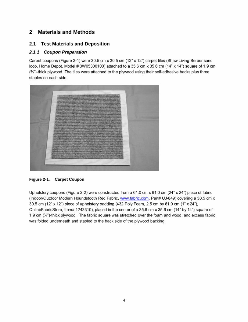
Carpet coupons (Figure 2-1) were 30.5 cm x 30.5 cm (12” x 12”) carpet tiles (Shaw Living Berber sand loop, Home Depot, Model # 3W05300100) attached to a 35.6 cm x 35.6 cm (14” x 14”) square of 1.9 cm (¾”)-thick plywood. The tiles were attached to the plywood using their self-adhesive backs plus three staples on each side.
Figure 2-1. Carpet Coupon
Upholstery coupons (Figure 2-2) were constructed from a 61.0 cm x 61.0 cm (24” x 24”) piece of fabric (Indoor/Outdoor Modern Houndstooth Red Fabric, www.fabric.com, Part# UJ-849) covering a 30.5 cm x 30.5 cm (12” x 12”) piece of upholstery padding (432 Poly Foam, 2.5 cm by 61.0 cm (1” x 24”), OnlineFabricStore, Item# 1243310), placed in the center of a 35.6 cm x 35.6 cm (14” by 14”) square of 1.9 cm (¾”)-thick plywood. The fabric square was stretched over the foam and wood, and excess fabric was folded underneath and stapled to the back side of the plywood backing.

5
Figure 2-2. Upholstery Coupon
Concrete coupons (Figure 2-3) were formed from Sakrete Sand Mix poured into custom 35.6 cm x 35.6 cm (14” by 14”) forms. The sand mix was prepared according to indications on the package using a trough and garden hose for the water supply. The coupon was smoothed with a trowel and allowed to set and dry overnight. The coupons were allowed to cure under humid conditions for at least five days.
Figure 2-3. Concrete Coupon
Mechanical MERV 8 HVAC filters were 35.6 cm x 35.6 cm x 2.5 cm (14” x 14” x 1”) Purafilter 2000 Blue series (Purafilter 2000, Las Vegas, NV; http://purafilter2000.com/products.php). Electrostatic MERV 8 filters were 35.6 cm x 35.6 cm x 2.5 cm (14” x 14” x 1”) Eco-Aire MERV 8 High Cap (Con-Air Industried, Inc., Orlando, FL). Stainless steel coupons were Grade 316, cut to 35.6 cm x 35.6 cm (14” by 14”) or 10.2 cm x 15.2 cm (4” x 6”). Only the centermost 30.5 cm x 30.5 cm (12” x 12”) of each 35.6 cm x 35.6 cm (14” by 14”) coupon was sampled.

6
All coupons were placed in sterilization bags and sterilized prior to use. Carpet and upholstery coupons were sterilized by a minimum 250 ppmv Vaporous Hydrogen Peroxide (VHP) cycle for four hours using a STERIS ED1000. Concrete and stainless steel coupons were sterilized prior to use by steam autoclave utilizing a gravity cycle program consistent with the EPA NHSRC Microbiology Laboratory Miscellaneous Operating Procedure (MOP) 6570 (see Appendix A for all associated MOPs). HVAC filters were sterilized with ethylene oxide. Sterility was evaluated by swab sampling one coupon from each sterilization batch according to MOP 3135. Prior to use, the coupons treated with VHP were incubated at 30-35 °C for a minimum of two days to force off-gassing of residual hydrogen peroxide (H2O2) from material coupons as suggested by Baron et al. [4], so that biocidal activity was prevented.
2.1.2 Bacillus Spore Preparation
The test organism for this work was a powdered spore preparation of B. atrophaeus (American Type Culture Collection (ATCC) 9372) and silicon dioxide particles. The preparation was obtained from the U.S. Army Dugway Proving Ground (DPG) Life Science Division, in Dugway Utah. The preparation procedure is reported in Brown et al. [5]. Briefly, after 80 – 90 percent sporulation, the suspension was centrifuged to generate a preparation of approximately 20 percent solids. A preparation resulting in a powdered matrix containing approximately 1 x 10¹¹ viable spores per gram was prepared by dry blending and jet milling the dried spores with fumed silica particles (Deguss, Frankfurt am Main, Germany). The powdered preparation was loaded into MDIs by the U.S. Army Edgewood Chemical Biological Center (ECBC) or by ARCADIS according to a proprietary protocol. Control checks for each MDI were included in the batches of coupons contaminated with a single MDI.
2.1.3 Coupon Inoculation
Coupons were inoculated with spores of B. atrophaeus from an MDI using the procedure described by Calfee et al. [6] and detailed in MOPs 3161-LD and 3161-HD for low dose (≤2 x 10⁴) and high dose (>2 x 10⁴) concentrations. Briefly, each coupon was inoculated independently by being placed into a separate aerosol dosing apparatus (ADA) designed to fit one 35.6 cm x 35.6 cm (14” by 14”) coupon of any thickness. In accordance with MOP 3161-LD or -HD, the MDI was discharged into the ADA a single time for most concentrations, but three discharges were administered when the 2 x 10² colony forming units (CFU) per dose MDI was used, for a total dose of ~6 x 10² CFU per coupon for these inoculations. The spores were allowed to settle onto the coupon surfaces for a minimum period of 18 h. When porous coupons were used (HVAC filters), coupons were placed on double-coated carpet tape (Polyken Model 105C) to prevent re-entrainment of spores during handling and sampling. After the minimum 18-h period, the coupons were then removed from the ADA and sampled. The ADAs were removed from only those coupons required for a single sample at a time (some samples were comprised of three coupons, others a single coupon). After use, the coupons were placed in a bin of soapy water before disposal. The handling of the contaminated coupons was done in a way to minimize or control spore dispersal. One person was tasked with removing the clamps holding the ADA to the coupon and the removal of the ADA and gasket from the coupon. A second person, wearing new gloves for each coupon, was then tasked with placing the sampling template atop the coupon. A third person executed the actual sample collection procedure (e.g., vacuum-device usage, wipe-based sample collection, etc). The first person then removed the coupon for neutralization. All personnel conducted the same job throughout the entirety of a test operation.

7
The MDIs are claimed to provide 200 discharges per MDI. The number of discharges per MDI was tracked so that use did not exceed this value. For any inoculation event for all three materials, a new MDI had to be used to avoid exceeding 200 discharges per MDI. Additionally, in accordance with MOP 3161-LD and -HD, the weight of each MDI was determined after completion of the inoculation of each coupon. For quality control of the MDIs, on each day of testing at least three reference stainless steel inoculation control coupons were inoculated simultaneously and interspersed with test coupons. The reference coupons were inoculated as the first, middle, and last coupons within a single group of coupons, all inoculated by the same MDI within a single test. These inoculation control (reference) coupons were a stainless steel coupon (35.6 cm by 35.6 cm) inoculated in accordance with MOP 3161-LD or -HD, sampled and analyzed in accordance with Section 2.3.2 or Section 2.3.3. If the results from the inoculation controls were outside the acceptance criteria (Table 4-2), the results were discussed immediately to determine the corrective action.
A log was maintained for each set of coupons that was dosed via the method of MOP 3161-LD or -HD. Each record contained the unique coupon identifier, the MDI unique identifier, the date, the operator, the weight of the MDI before dissemination into the coupon dosing device, the weight of the MDI after dissemination, and the difference between these two weights. The coupon codes were pre-printed on the log sheet prior to the start of coupon inoculation (dosing).
A second method was used to inoculate HVAC filters under air flow (~1000 cubic feet per minute, CFM). To provide the flow, the back of the filter was connected to a blower from a high-volume air sampler (Thermo Scientific High Volume Air Sampler VFC-PM10.for FRM RFPS-1287-063 (https://www.thermo.com/eThermo/CMA/PDFs/Various/File_52267.pdf)). The outlet of the blower was directed to the intake of the H130 enclosure exhaust system to control contamination from breakthrough. On top of the filter was an ADA assembled exactly as described in MOP 3161-LD or -HD. Positioned between the HVAC filter and the blower, a sterile quartz filter was used to collect any spores that escaped capture by the HVAC filter (see Figure 2-4). The quartz filter was installed as outlined in MOP 3168. The blower was operated for 15 sec, then the MDI was activated, and the blower operated for another 15 sec before deactivation. Once the blower ceased, the filter and ADA were lifted from the blower assembly and placed on carpet tape as the filters inoculated using the first method. The quartz filter was collected as outlined in MOP 3168. The blower adapter was cleaned and decontaminated between coupons with Dispatch™ disinfectant wipes (Clorox Corp, CA), followed by 3% sodium thiosulfate (STS) and ethanol wipes. This method is described in more detail in MOP 3161-F.

8
Figure 2-4. Schematic of Deposition Apparatus for Inoculation under Flow Conditions
Additionally, after a coupon was dosed via the above procedure, the coupon was labeled with the unique identifier described in Section 2.5.5. The identification (ID) was written on the ADA with a Sharpie or equivalent permanent marker.
35.6 cm x 35.6 cm HVAC filter
20.3 cm x 25.4 cm Quartz filter
ADAdapter
35.6 cm x 35.6 cm ADA
Hi-Vol Blower assembly
Flow

9
2.2 Test Matrix Testing was conducted in three phases. Data from the first phase of testing were used to compare recoveries from the various vacuum devices. The second phase was designed to perform side-by-side comparisons of the two devices with the highest recoveries (from Phase 1) when used to collect spores from HVAC filters. The third phase was designed to better understand the variability between different laboratories in performing the inoculation, recovery, and extraction activities. The Phase 1 test matrix is shown in Table 2-1.
Table 2-1. Phase 1Test Matrix
Vacuum Device Material Target
Inoculum (CFU/coupon)
Replicate Test Samples (Total
number of coupons)
Negative Controls Samples
Total Coupons
Method 1 (Vacuum sock – fast sampling)
Carpet 107 10 (30 coupons) 1 (3 coupons) 33
Upholstery 107 10 (30 coupons) 1 (3 coupons) 33
Concrete 107 10 (30 coupons) 1 (3 coupons) 33
Method 1 (Vacuum sock – slow sampling)
Carpet 107 10 (30 coupons) 1 (3 coupons) 33
Upholstery 107 10 (30 coupons) 1 (3 coupons) 33
Concrete 107 10 (30 coupons) 1 (3 coupons) 33
Method 2 (37 mm MCE)
Carpet 107 10 coupons 1 coupon 11
Upholstery 107 10 coupons 1 coupon 11
Concrete 107 10 coupons 1 coupon 11
Method 3 (Trace Evidence
Filter)
Carpet 107 10 (30 coupons) 1 (3 coupons) 33
Upholstery 107 10 (30 coupons) 1 (3 coupons) 33
Concrete 107 10 (30 coupons) 1 (3 coupons) 33
Method 4 (37 mm PTFE)
Carpet 107 10 coupons 1 coupon 11
Upholstery 107 10 coupons 1 coupon 11
Concrete 107 10 coupons 1 coupon 11
MCE = Mixed Cellulose Ester, PTFE = Polytetrafluoroethylene
Vacuum methods applicable to large areas were challenged with three coupons per sample (Methods 1 and 3), while methods requiring a longer sample time per area were challenged with only one coupon per sample (Methods 2 and 4).
The Phase 2 test matrix is shown in Table 2-2.
10
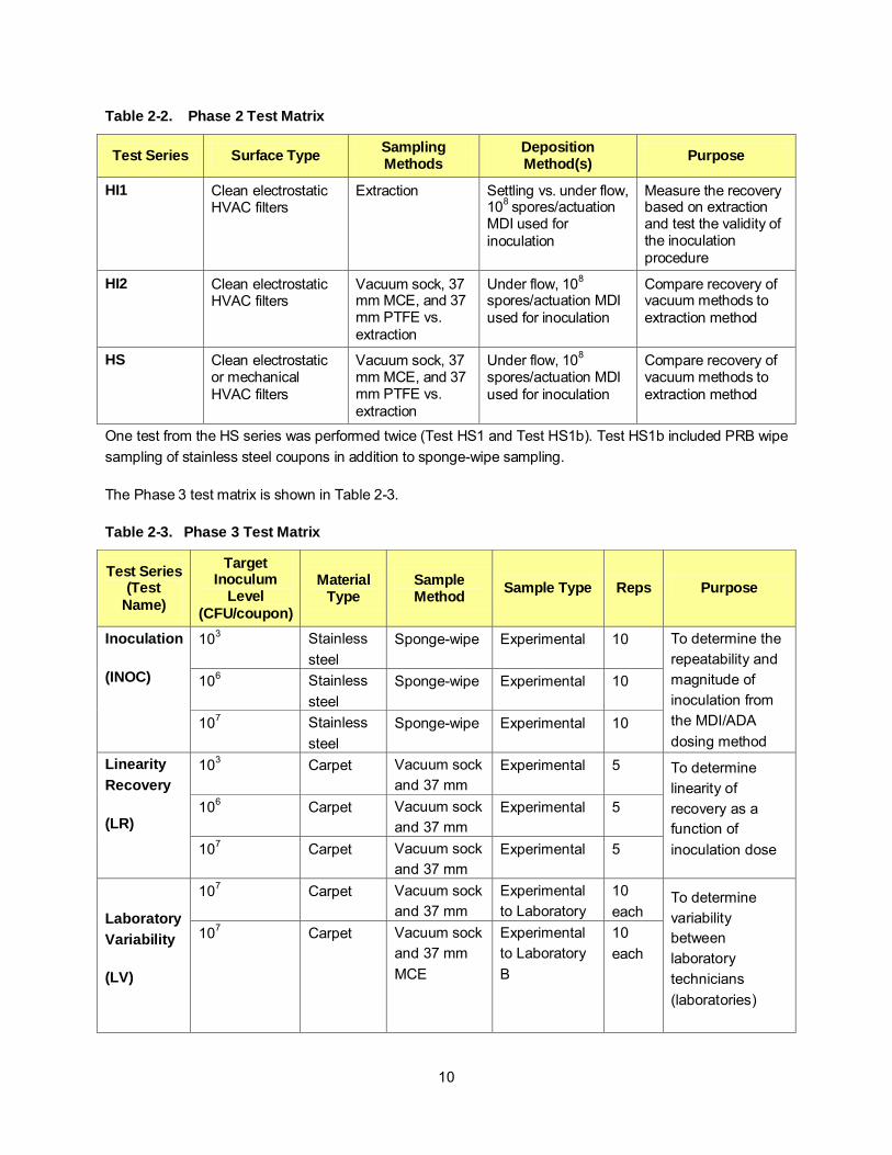
Table 2-2. Phase 2 Test Matrix
Test Series Surface Type Sampling Methods
Deposition Method(s) Purpose
HI1 Clean electrostatic HVAC filters
Extraction Settling vs. under flow, 108 spores/actuation MDI used for inoculation
Measure the recovery based on extraction and test the validity of the inoculation procedure
HI2 Clean electrostatic HVAC filters
Vacuum sock, 37 mm MCE, and 37 mm PTFE vs. extraction
Under flow, 108 spores/actuation MDI used for inoculation
Compare recovery of vacuum methods to extraction method
HS Clean electrostatic or mechanical HVAC filters
Vacuum sock, 37 mm MCE, and 37 mm PTFE vs. extraction
Under flow, 108 spores/actuation MDI used for inoculation
Compare recovery of vacuum methods to extraction method
One test from the HS series was performed twice (Test HS1 and Test HS1b). Test HS1b included PRB wipe sampling of stainless steel coupons in addition to sponge-wipe sampling.
The Phase 3 test matrix is shown in Table 2-3.
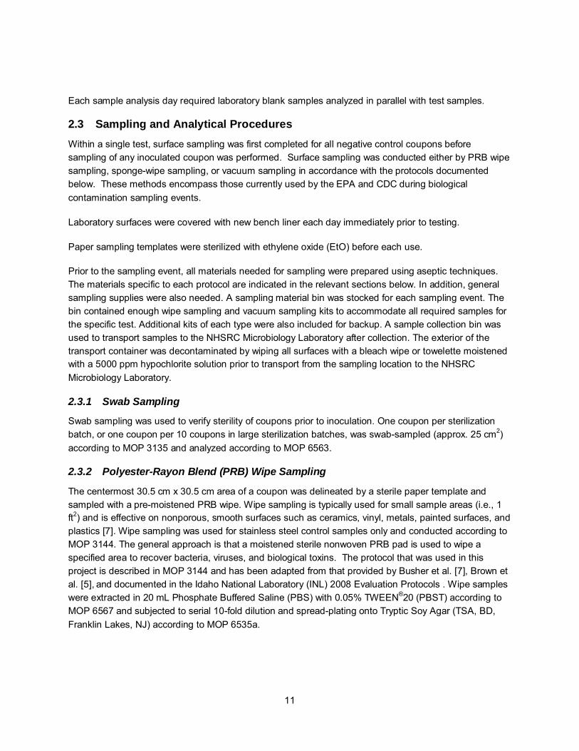
Table 2-3. Phase 3 Test Matrix
Test Series (Test
Name)
Target Inoculum
Level (CFU/coupon)
Material Type
Sample Method Sample Type Reps Purpose
Inoculation
(INOC)
103 Stainless steel
Sponge-wipe Experimental 10 To determine the repeatability and magnitude of inoculation from the MDI/ADA dosing method
106 Stainless steel
Sponge-wipe Experimental 10
107 Stainless steel
Sponge-wipe Experimental 10
Linearity Recovery
(LR)
103 Carpet Vacuum sock and 37 mm
Experimental 5 To determine linearity of recovery as a function of inoculation dose
106 Carpet Vacuum sock and 37 mm
Experimental 5
107 Carpet Vacuum sock and 37 mm
Experimental 5
Laboratory Variability
(LV)
107 Carpet Vacuum sock and 37 mm
Experimental to Laboratory
10 each
To determine variability between laboratory technicians (laboratories)
107 Carpet Vacuum sock and 37 mm MCE
Experimental to Laboratory B
10 each
11
Each sample analysis day required laboratory blank samples analyzed in parallel with test samples.
2.3 Sampling and Analytical Procedures Within a single test, surface sampling was first completed for all negative control coupons before sampling of any inoculated coupon was performed. Surface sampling was conducted either by PRB wipe sampling, sponge-wipe sampling, or vacuum sampling in accordance with the protocols documented below. These methods encompass those currently used by the EPA and CDC during biological contamination sampling events.
Laboratory surfaces were covered with new bench liner each day immediately prior to testing.
Paper sampling templates were sterilized with ethylene oxide (EtO) before each use.
Prior to the sampling event, all materials needed for sampling were prepared using aseptic techniques. The materials specific to each protocol are indicated in the relevant sections below. In addition, general sampling supplies were also needed. A sampling material bin was stocked for each sampling event. The bin contained enough wipe sampling and vacuum sampling kits to accommodate all required samples for the specific test. Additional kits of each type were also included for backup. A sample collection bin was used to transport samples to the NHSRC Microbiology Laboratory after collection. The exterior of the transport container was decontaminated by wiping all surfaces with a bleach wipe or towelette moistened with a 5000 ppm hypochlorite solution prior to transport from the sampling location to the NHSRC Microbiology Laboratory.
2.3.1 Swab Sampling
Swab sampling was used to verify sterility of coupons prior to inoculation. One coupon per sterilization batch, or one coupon per 10 coupons in large sterilization batches, was swab-sampled (approx. 25 cm2) according to MOP 3135 and analyzed according to MOP 6563.
2.3.2 Polyester-Rayon Blend (PRB) Wipe Sampling
The centermost 30.5 cm x 30.5 cm area of a coupon was delineated by a sterile paper template and sampled with a pre-moistened PRB wipe. Wipe sampling is typically used for small sample areas (i.e., 1 ft2) and is effective on nonporous, smooth surfaces such as ceramics, vinyl, metals, painted surfaces, and plastics [7]. Wipe sampling was used for stainless steel control samples only and conducted according to MOP 3144. The general approach is that a moistened sterile nonwoven PRB pad is used to wipe a specified area to recover bacteria, viruses, and biological toxins. The protocol that was used in this project is described in MOP 3144 and has been adapted from that provided by Busher et al. [7], Brown et al. [5], and documented in the Idaho National Laboratory (INL) 2008 Evaluation Protocols . Wipe samples were extracted in 20 mL Phosphate Buffered Saline (PBS) with 0.05% TWEEN®20 (PBST) according to MOP 6567 and subjected to serial 10-fold dilution and spread-plating onto Tryptic Soy Agar (TSA, BD, Franklin Lakes, NJ) according to MOP 6535a.

12
2.3.3 Sponge-wipe Sampling
The centermost 30.5 cm x 30.5 cm area of the coupon was delineated by a sterile paper template and sampled with a pre-moistened sponge. Sponge-wipe samples, described in MOP 3165, were collected using the following five patterns: (1) using the flat side of the sponge-wipe, the surface was sampled using horizontal S-strokes, covering the entire template area; (2) the sponge-wipe was then flipped over to the opposite side to sample the surface in a vertical pattern, covering the entire template area; (3) using the narrow edges of the sponge-wipe, the surface was sampled using the same S-strokes but applied diagonally across the template, (4) rotating the sponge to use the opposite side starting at the midway point of the coupon; and (5) the tip of the sponge-wipe was then used to sample the perimeter of the sampling area. The sampling method is described in detail in the study Rose et al. [8] and are consistent with the CDC-developed field collection procedures (www.cdc.gov/niosh/topics/emres/surface-sampling-bacillus-anthracis.html). Sponge-wipe samples were extracted in 90 mL PBST as described in MOP 6580 and subjected to 10-fold serial dilution and spread-plating according to MOP 6535a.
2.3.4 Vacuum Sock Sampling and Analysis
Vacuum sock sampling was conducted in accordance with MOP 3145 with the following modification: three coupons were vacuumed per sample for some Phase 1 tests. A single coupon was vacuumed for Phase 2 and 3 tests. The centermost 30.5 cm x 30.5 cm (12” x 12”) square area was vacuumed on each coupon. For Phase 1, vacuum sock nozzles were moved across the coupon at two speeds, approximately 1 sec per 30.5 cm pass (fast) and approximately 3 sec per 30.5 cm pass (slow). For example, on one square foot of surface area (30.5 cm x 30.5 cm), sampling with the vacuum sock (slow) or vacuum sock (fast) required approximately 60 passes each (30 passes in one direction, then 30 additional passes in a direction oriented 90 degrees to the first), and approximately 240 or 90 sec, respectively. For the three coupon sample, the collection time required was 720 or 270 sec for the slow or fast method, respectively. Each speed was considered a different vacuum method. All vacuum samples were collected using an OmegaVac (Atrix, Int.; Burnsville, MN), which supplied airflow of approximately 2000 L min-1. This equipment was powered by alternating current (120 V) supplied by a wall receptacle. Phases 2 and 3 used only the slow speed technique. Vacuum socks were extracted in 20 mL PBST according to MOP 6572 and subjected to 10-fold serial dilution and spread-plating according to MOP 6535a. Figure 2-5 shows an assembled vacuum sock kit with cardboard nozzle and connection tubes, and the vacuum sock removed from the tubes.

13
Figure 2-5. Vacuum Sock Kit and Individual Sock.
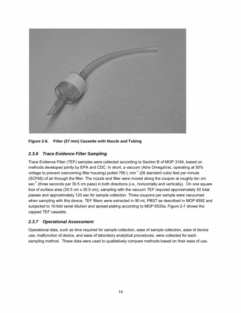
2.3.5 37 mm MCE and 37 mm PTFE Sampling
Filter samples (37 mm MCE and PTFE) were collected according to Section A of MOP 3164, based on methods developed jointly by EPA and CDC. In short, a vacuum pump (Vac-U-Go, SKC, Inc., Eighty Four, PA) at the back end of the filter pulled 20 L min-1 of air through the filter. This pump was powered by 120 V alternating current supplied by a wall receptacle. A section of Tygon (~3 cm ) tubing was cut to an angle of 45° on one end, the non-angled terminus was attached to the cassette via a polyvinyl chloride (PVC) adapter (SKC, Inc., P/N 225-132A), and the angled end was used as a nozzle. The nozzle and filter were moved along the coupon at roughly ten cm sec-1 (three seconds per 30.5 cm pass) in both directions (i.e., horizontally and vertically). For example, on one square foot of surface area (30.5 cm x 30.5 cm), sampling with the 37 mm cassette (MCE or PTFE) required approximately 100 total passes and approximately 400 sec. A single coupon was vacuumed when sampling with either of these two devices. The nozzle was extracted separately (described in MOP 6579), the nozzle extract was then combined with the filter extraction vessel, and filter extraction commenced. The combined resulting extract was subjected to 10-fold serial dilution and spread-plating according to MOP 6535a.
Figure 2-6 shows the 37 mm cassette with nozzle and tubing.
14
Figure 2-6. Filter (37 mm) Cassette with Nozzle and Tubing
2.3.6 Trace Evidence Filter Sampling
Trace Evidence Filter (TEF) samples were collected according to Section B of MOP 3164, based on methods developed jointly by EPA and CDC. In short, a vacuum (Atrix OmegaVac, operating at 50% voltage to prevent overcoming filter housing) pulled 790 L min-1 (28 standard cubic feet per minute (SCFM)) of air through the filter. The nozzle and filter were moved along the coupon at roughly ten cm sec-1 (three seconds per 30.5 cm pass) in both directions (i.e., horizontally and vertically). On one square foot of surface area (30.5 cm x 30.5 cm), sampling with the vacuum TEF required approximately 30 total passes and approximately 120 sec for sample collection. Three coupons per sample were vacuumed when sampling with this device. TEF filters were extracted in 90 mL PBST as described in MOP 6582 and subjected to 10-fold serial dilution and spread-plating according to MOP 6535a. Figure 2-7 shows the capped TEF cassette.
2.3.7 Operational Assessment
Operational data, such as time required for sample collection, ease of sample collection, ease of device use, malfunction of device, and ease of laboratory analytical procedures, were collected for each sampling method. These data were used to qualitatively compare methods based on their ease of use.

15
Figure 2-7. 3M® Trace Evidence Filter (TEF) Vacuum-based Sampling Device
2.3.8 HVAC filter extraction
Sections (930 cm2, 1 ft2) of HVAC filters were excised and further cut into half or quarter sections (15.3 cm x 30.5 cm (6” x 12”) or 15.3 cm x 15.3 cm (6” x 6”)) and using sterile scissors, folded, and placed in a sterile 1 L container (one section per container). The size chosen for filter sub-sections was based upon optimization experiments conducted with the same 1 L containers at CDC (data not shown). Excision and sectioning of the filter typically required 90 sec (each 30.5 cm x 30.5 cm (12” x 12”) section) once cutting was initiated. HVAC filters were then extracted in PBST for 30 min using an orbital shaker (300 rpm). Quarter-sections of the filters were extracted in 500 mL PBST, while half-sections of the filters were extracted in 700 mL PBST. Details on the method are provided in MOP 6593.
2.3.9 Quartz extraction
Quartz filters were extracted in 100 mL of PBST as described in MOP 6586.
2.3.10 Direct Extraction of Stainless Steel
Six 15.3 cm x 30.5 cm (4” x 6”) stainless steel coupon parts were aseptically transferred straight from the ADA to a sterile 10L beaker. Two sterile glass rods, bent symmetrically at a 90 degree angle, were placed in the bottom of the beaker, followed by one sextant of the inoculated coupon, followed by another two sterile glass rods. The process of stacking the glass rods and coupons continued until there were no more inoculated coupon pieces. Each coupon was placed in the beaker so the inoculated side was upright. The glass beaker was sealed (sterile aluminum foil; the same foil with which the beaker was autoclaved) and transported to the NHSRC Microbiology Laboratory for extraction.

16
Sterile PBST (1.5 liters) was aseptically added to the 10L beaker containing the sample and then re-sealed with the aluminum foil. The entire beaker was placed into an ultrasonic cleaner (Branson model 8510, Danbury, CT) and the sample was sonicated (40 kHz) for 15 min. Immediately following sonication, 1L of extraction liquid was removed and transferred to a 1L specimen container. The sample was then homogenized by manual agitation/swirling before being 10-fold serially diluted and plated according to MOP 6535a.
2.4 Sampling Strategy 2.4.1 Sampling/Monitoring Points
The experimental samples are listed in Section 2.2. For each inoculation event, additional samples collected from stainless steel surfaces were used as control samples. These control samples included wipe samples (used as inoculation controls or reference coupons) and vacuum samples (to compare collection efficacy among vacuum sampling methods). Wipe and vacuum samples were collected by sampling within a 30.5 cm x 30.5cm (12” x 12”) sampling template (SKC, Inc., P/N 225-2416) centered on the coupons. Direct extraction techniques were also used to quantify inoculation levels on stainless steel and HVAC filters. Each coupon was sampled only once.
The time required to collect and analyze vacuum samples, both singly and in the aggregate, was logged in the laboratory notebook.
Table 2-4 lists the samples collected for each test.
17
Table 2-4. Frequency of Sampling Monitoring Events
Sample Type Sample Number Purpose
Vacuum sample 3 to 10 per test condition per coupon material
To determine the number of viable spores recovered via the vacuum method
Negative coupon sample (vacuum sample of sterile coupon)
1 per vacuum method per test To determine extent of cross-contamination from coupon handling and sampling
Field blank sample (1 minute sample of laboratory air)
1 per vacuum method per test To determine extent of cross-contamination from laboratory air
Positive control coupons sampled either by extraction, wipe, or sponge
1 set of 3 stainless steel coupons per sampling method inoculated at the beginning, middle, and end of test coupon inoculations
To provide the best estimate of the number of viable spores deposited onto the material test coupons
Swab samples 1 per material or equipment per sterilization batch
To demonstrate sterility of coupons and inoculation materials
Microbiology Laboratory material blanks
3 per material To demonstrate sterility of extraction and plating materials
Table 2-5 lists the critical and noncritical measurements for each sample.
Table 2-5. Critical and Non-Critical Measurements
Sample Type Critical Measurements Non-critical Measurement
Vacuum sample Plated volume, incubation temperature, extracted volume, CFU, collection area
Storage time, storage temperature, collection time, extraction time
Negative coupon sample (vacuum sample of sterile coupon)
Plated volume, incubation temperature, extracted volume, CFU, collection area
Storage time, storage temperature, collection time, extraction time
Field blank sample (1 minute sample of laboratory air)
Plated volume, incubation temperature, extracted volume, CFU
Storage time, storage temperature, collection time, extraction time
Positive control coupons sampled either by extraction, wipe, or sponge
Plated volume, incubation temperature, extracted volume, CFU
Storage time, storage temperature, collection time, extraction time
Swab samples Plated volume, incubation temperature, extracted volume, CFU
Storage time, storage temperature
Microbiology Laboratory material blanks
Plated volume, incubation temperature, extracted volume, CFU
Storage time, storage temperature

18
2.5 Sampling Handling and Custody 2.5.1 Preventing Cross-contamination during Coupon Preparation
Coupon preparation included the activities performed on each pre-fabricated material coupon and procedural blank coupon prior to the inoculation procedure. Sterilization methods depended on the sample type: concrete coupons were sterilized using the gravity cycle of the autoclave; carpet and upholstery coupons were sterilized using VHP. Swab sampling of coupons from sterilization batches were used to confirm sterility of the materials after sterilization. The sterilization procedure was repeated if results were positive for the target organism. Swabs showing foreign contamination could be cause for repeating the sterilization procedure or taking other corrective action. The blank coupon sampling occurred before sampling of any inoculated coupons.
2.5.2 Preventing Cross-contamination during Sampling
Sampling poses a significant opportunity for cross-contamination of samples. In an effort to minimize the potential for cross-contamination, several management controls were followed.
• In accordance with aseptic technique, a sampling team made up of a “sampler,” a “support person,” and a “sample handler” was utilized.
• The sample handler was the only person to handle deposition pyramids (ADAs) or material coupons during the sampling event. The support person had the responsibility of handing sterile templates to the sampler.
• The sampler handled only the sampling media and the support person handled all other supplies. The sampler sampled the surface according to the appropriate procedure as described in Section 2.3.
• The collection medium was then placed into a sample container that was opened, held and closed by the support person.
• The sealed sample was handled only by the support person.
• All of the following actions were performed only by the support person, using aseptic technique:
o The sealed bag with the sample was placed into another sterile plastic bag that was then sealed; that bag was then decontaminated using a bleach wipe.
o The double-bagged sample was then placed into a third sterile bag that was sealed and then placed into a sterile sample container for transport.
o The exterior of the transport container was decontaminated by wiping all surfaces with a bleach wipe or towelette moistened with a solution of 5000 ppm hypochlorite prior to transport from the sampling location to the NHSRC Microbiology Laboratory.
• After the sample was placed into the container for transport, the sample handling team placed the sampled coupon in soapy water for eventual disposal.
The sampling crew then changed their gloves in preparation for working with the next sample.
Additionally, and equally important, the order of sampling was as follows: (1) first field blank; (2) all blank coupons; (3) second field blank (when required by test plan); (4) inoculated coupons; and (5) last field
19
blank (when required by test plan). This order ensured that test coupons were handled in an order from least level of contamination to the most, and field blank control samples provided evidence that samples were handled properly, without cross-contamination.
2.5.3 Preventing Cross-contamination during Analysis
General aseptic laboratory technique was followed and was embedded in the standard operating procedures (SOPs) and MOPs used by the NHSRC Microbiology Laboratory to recover and plate samples. The SOPs and MOPs document the aseptic technique employed to prevent cross-contamination. Additionally, the order of analysis was (1) all blank coupons, then (2) all inoculated coupons.
2.5.4 Sample Containers
For each PRB wipe sample, the primary containment was an individual sterile 50 mL conical tube. Conical tubes (15mL) were primary containment for swab samples. Secondary containment for swab and PRB wipe samples was sterile sampling bags. The sponge-wipe primary containment was the stomacher bag used for extraction, and secondary containment was sterile sampling bags. The primary containment of the vacuum sock was a sterile sampling bag. A four inch cable tie was also used to close the open end of the newly-collected vacuum sock sample. The secondary containment of each vacuum method sample was separate sterile sampling bags. All biological samples from a single test were then placed in a sterilized container. After samples were placed in the container for storage and transport to the NHSRC Microbiology Laboratory, the container was wiped with a towelette saturated with a ≥5000 ppm hypochlorite solution. A single container was used for storage of materials during sampling and for transport of samples to the NHSRC Microbiology Laboratory.
2.5.5 Sample Identification
Each coupon or sample was identified by a unique sample ID. The sampling team maintained an explicit laboratory log which included records of each unique sample ID and its associated test number, inoculum level, sampling method, and the date sampled. Each coupon was marked with only the material descriptor and unique code number. Sample IDs included descriptors, where necessary, for project number (WA 10), test ID, coupon material type, vacuum or other sample type, inoculation type, sample purpose (test, control, field blank, etc.) and replicate number. The sample codes eased written identification. A typical sample ID was 10-HS1-F-V-4, which identified the sample as from WA 10, Test HS1, inoculated under Flow, sampled by Vacuum sock, replicate 4. Once samples were transferred to the NHSRC Microbiology Laboratory for microbiological analysis, each sample (plate) was additionally identified by replicate number and dilution. The NHSRC Microbiology Laboratory also included on each plate the date it was placed in the incubator.
The samples from blank coupons had a two-letter material code, with the first letter being “X”.
The sequence number was added to the test number to distinguish control samples in the case where all materials were not inoculated at the same time for a single vacuum method. For instance, a stainless steel PRB wipe sample control coupon for Test 1 for carpet and upholstery may be labeled 10-1.1-S-W-1, while for the concrete, inoculated on a different day, the sample would be labeled 10-1.2-S-W-1.

20
2.5.6 Information Recorded by Field Personnel
The sampling team members’ names, date, run number, and all sample codes with corresponding coupon codes were recorded in the laboratory notebook, along with sample times and durations. Any deviations from sampling protocols were documented in the laboratory notebook, along with any observations.
Digital video was collected during sampling of each material using each vacuum method in order to document the process.
2.5.7 Sample Preservation
Following transfer to the NHSRC Microbiology Laboratory, all samples were stored at 4 ± 2 °C until analyzed. All samples were allowed to equilibrate at room temperature for one hour prior to analysis.
2.5.8 Sample Holding Times
After sample collection for a single test was complete, all biological samples were transported to the NHSRC Microbiology Laboratory immediately, with appropriate chain of custody (COC) form(s). Liquid samples were stored no longer than 24 h prior to analysis. Samples of other matrices were stored no longer than five days before the primary analysis. Typical hold times, prior to analyses, for most biological samples was ≤ two days.
2.5.9 Sample Custody
Careful coordination with the NHSRC Microbiology Laboratory was required to achieve successful transfer of uncompromised samples in a timely manner for analysis. Test schedules were confirmed with the Microbiology Laboratory prior to the start of each test. To ensure the integrity of samples and to maintain a timely and traceable transfer of samples, an established and proven chain of custody or possession is mandatory. Accurate records were maintained whenever samples were created, transferred, stored, analyzed, or destroyed. The primary objective of these procedures was to create an accurate written record that could be used to trace the possession of the sample from the moment of its creation through the reporting of the results. A sample was in custody in any one of the following states:
• In actual physical possession • In view, after being in physical possession • In physical possession and locked up so that no one could tamper with it • In a secured area, restricted except to authorized personnel • In transit.
Laboratory test team members received copies of the test plans prior to each test. Pre-study briefings were held to apprise all participants of the objectives, test protocols, and COC procedures to be followed. These protocols were required to be consistent with any protocols established by EPA. In the transfer of custody, each custodian signed, recorded, and dated the transfer on the COC. Sample transfer could be on a sample-by-sample basis or on a bulk basis. The following protocol was followed for all samples as they were collected and prepared for distribution: • A COC record accompanied the samples. When turning over possession of samples, the transferor
and recipient signed, dated, and noted the time on the record sheet. This record sheet allowed

21
transfer of custody of a group of samples from the sample collection laboratory to the NHSRC Microbiology Laboratory.
• If the custodian had not been assigned, the laboratory operator had the responsibility of packaging the samples for transport. Samples were carefully packed and hand-carried between on-site laboratories. The COC record showing the identity of the contents accompanied all packages.
2.5.10 Sample Archiving
All samples and diluted samples were archived for a minimum of two weeks following completion of analysis. This time allowed for review of the data to determine if any re-plating of selected samples was required. Samples were archived by maintaining the primary extract at 4 ± 2 °C in a sealed extraction vessel.
2.6 Statistical Analysis Methods Relative recovery data were analyzed using a one-way analysis of variance (ANOVA). A three-way ANOVA model with full interactions between Device, Material, and Experiment/Control was used to analyze raw recovery data. For the three-way ANOVA, mean log10 reduction was then computed as a linear contrast of model coefficients to assess recovery rate. Mean differences in log10 reduction between devices were also computed as linear contrasts. Statistical significance (p ≤ 0.05) of differences between devices was then assessed via t-tests on the contrasts, and two sets of p-values were computed. First, p-values were computed without adjusting for multiple comparisons. Subsequently, p-values which accounted for multiple comparisons were computed, based on the multivariate t-distribution of the test statistics.
Both statistical methods were deemed valid by a statistical contractor (Neptune, Inc.). The advantage of the one-way ANOVA is that it compared relative recovery data that were normalized across experiments (normalized by PRB wipe recoveries). The disadvantage is that one-way ANOVA is not robust with regards to multiple sources of variation (i.e., variation in treatment groups and variation in control recoveries). The three-way ANOVA compared recoveries of the sampling methods using raw recovery values, and included recovery data from PRB wipe samples as a treatment group. While this method accounted for multiple sources of variation and interaction, the method, as used, was less robust for direct comparisons of sampling methods across tests.
The results of both statistical approaches are presented and discussed.
22
3 Results and Discussion
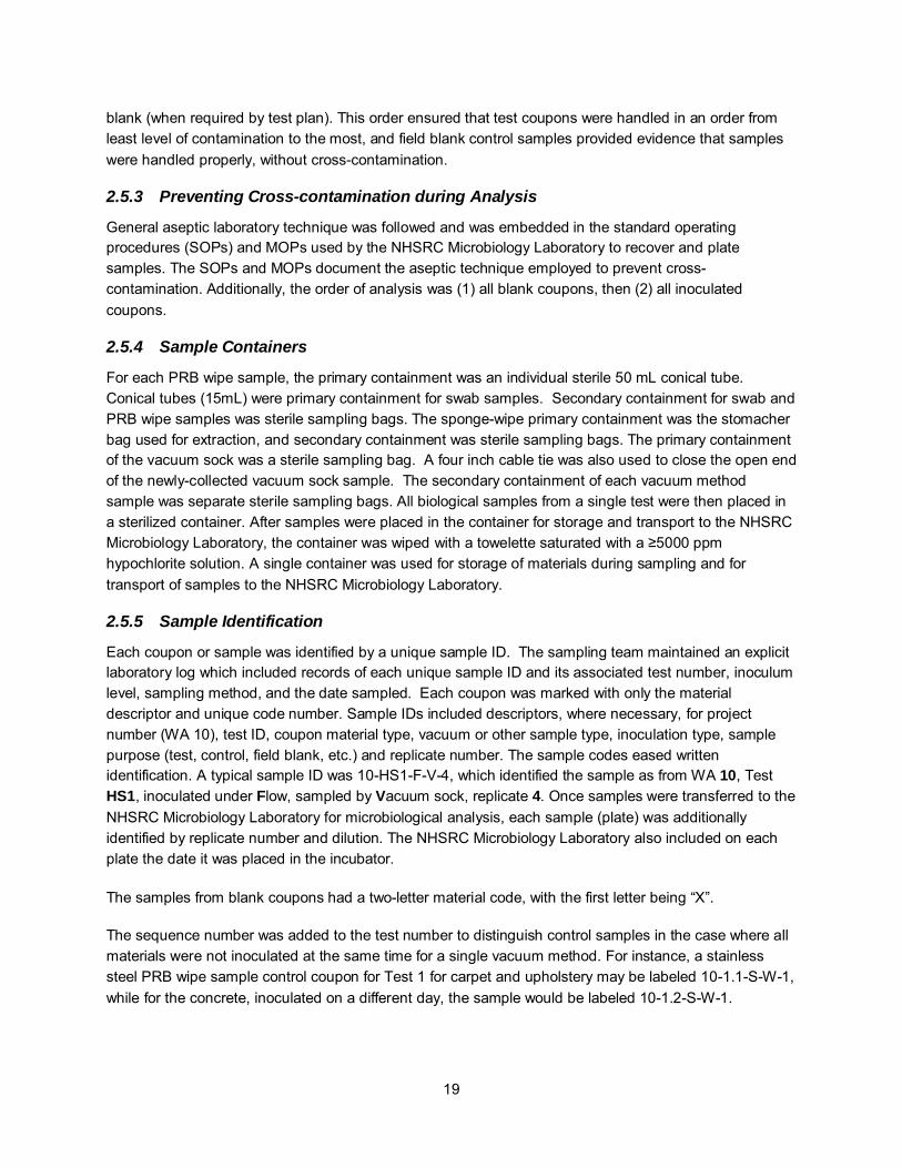
3.1 Phase 1 The results of the vacuum method scoping tests comparing recovery of five techniques from three materials are summarized in Table 3-1 and Figure 3-1.
Table 3-1. Recovery from Materials for each Vacuum Method
Mean CFU/cm2 (n = 10) (Standard Deviation in parentheses)
Material Vacuum Sock – Fast Speed
Vacuum Sock – Slow Speed 37 mm MCE TEF 37 mm PTFE
Carpet 2.01 x 10⁴ (9.33 x 10³)
2.66 x 10⁴ (8.49 x 10³)
2.83 x 10⁴ (1.19 x 10⁴)
1.28 x 10⁴ (2.21 x 10³)
2.18 x 10⁴ (1.05 x 10⁴)
Concrete 1.44 x 10⁴ (3.55 x 10³)
3.18 x 10⁴ (5.55 x 10³)
7.41 x 10⁴ (3.88 x 10⁴)
3.47 x 10⁴ (1.06 x 10⁴)
2.57 x 10⁴ (1.49 x 10⁴)
Upholstery 1.86 x 10⁴ (4.16 x 10³)
7.29 x 10³ (2.73 x 10³)
2.08 x 10⁴ (5.64 x 10³)
3.76 x 10³ (3.78 x 10³)
1.39 x 10⁴ (8.60 x 10³)
Figure 3-1. Recovery from Materials for each Vacuum Method. Data are plotted on a log-scale, as mean ± standard deviation.
These data are standardized for number of coupons sampled, with three coupons per sample for all methods except the 37 mm MCE and PTFE methods, which used only one coupon. Even without this standardization, the 37 mm MCE vacuum method shows higher recoveries from concrete (i.e., more
1.00E+03
1.00E+04
1.00E+05
1.00E+06
Carpet Concrete Upholstery
Reco
very
(CFU
cm
-2)
vacuum sock - fast
vacuum sock - slow
37 mm MCE
TEF
37 mm PTFE

23
spores recovered by this method even though surface area sampled was one-third that of the vacuum sock and TEF methods).
To account for differing inoculation levels achieved across numerous test days and MDIs, recovery was further standardized by normalizing vacuum recoveries to PRB wipe samples collected from stainless steel coupons inoculated by the same MDI and collected on the same test day as the test samples. Figure 3-2 and Table 3-2 summarize these results. Interestingly, the 37 mm MCE method demonstrated higher recovery on concrete than the wipe-based method on stainless steel, resulting in a relative recovery ≥100%. One explanation is that the 37 mm MCE device efficiently collected fine dust or debris particles from the concrete surface. Spores bound to these debris particles may have been collected more efficiently as a consequence, because the ease of particle resuspension from surfaces increases proportionately with cross-sectional area (i.e., larger particles are more easily resuspended than smaller particles).
Figure 3-2. Relative Recovery – Data presented as mean relative recovery (RR). RR calculated as percent of wipe recovery from stainless steel surface.
Table 3-2. Relative Recoveries from all Devices and Material Surface Types
Average CFU/cm2 vacuum method / Average CFU/cm2 stainless steel wipe
Vacuum Sock – Fast Speed
Vacuum Sock – Slow Speed 37 mm MCE TEF 37 mm PTFE
Concrete 30% 26% 124% 41% 24%
Upholstery 23% 11% 35% 3% 13%
Carpet 39% 64% 47% 12% 20%
0%
20%
40%
60%
80%
100%
120%
140%
Concrete Upholstery Carpet
Rel
ativ
e R
ecov
ery
(%)
Vacuum sock - fast
Vacuum sock - slow
37 mm MCE
TEF
37 mm PTFE

24
The null hypothesis that recoveries obtained during slow operation of the vacuum sock nozzle were not significantly different (p > 0.05) from the recoveries obtained during fast operation was not disproven by these tests. Recovery using the slow vacuum sock method was higher from carpet coupons but lower (than the fast vacuum sock method) from upholstery and concrete coupons, possibly due to the rapid motion of the nozzle agitating the coupon surface. Operation of the vacuum sock nozzle is expected to be highly variable between individual operators. Based on these data, operational variability may not greatly affect recoveries.
Preliminary research (based upon direct spiking, conducted at the CDC) suggested that recovery from PTFE was higher than recovery from MCE for the 37 mm filter media. The current data suggest that overall recovery (collection from the surface, retention on the filter, then extraction from the filter) with MCE filters was higher. The TEF vacuum method performed poorly for upholstery and carpet coupons, compared to the other methods. The sock (slow) method performed poorly on upholstery.
3.1.1 Results of Statistical Analyses
For carpet, the slow vacuum sock method has the highest recovery rate (one-way ANOVA, p ≤ 0.001). When analyzed by three-way ANOVA without correcting for multiple comparisons, the vacuum sock had significantly higher recoveries than the 37mm PTFE (p = 0.004) and TEF (p = 0.003) methods. On carpet, none of the method comparisons were statistically significant after correcting for multiple comparisons (three-way ANOVA, p > 0.05).
For concrete, the 37mm MCE method demonstrated the highest recovery (one-way ANOVA, p ≤ 0.001). Contrasts of the methods were also significant when analyzed by three-way ANOVA, before adjusting for multiple comparisons (all p ≤ 0.02). After adjusting for multiple comparisons, the 37mm MCE recoveries were statistically significant only when contrasted with recoveries of the 37 mm PTFE method (p = 0.03).
For upholstery, the 37 mm MCE method demonstrated the highest recovery (one-way ANOVA, p ≤ 0.001). When analyzed by three-way ANOVA, the recoveries using the 37 mm MCE method were significantly higher than those of the 37 mm PTFE, TEF, and slow vacuum sock methods. After adjusting for multiple comparisons, was the 37 mm MCE method recoveries were only statistically higher than those using the TEF method. The TEF method demonstrated the lowest recovery for upholstery compared to all other devices. This result was statistically significant even after adjusting for multiple comparisons (three-way ANOVA, all p ≤ 0.001).
3.1.2 Operational Parameters
3.1.2.1 Sampling Time and Ease
As discussed above, two sampling durations were used for vacuum sock sampling. Based on those data, there was conflicting effects of sampling time on vacuum sock samples.
For the 37 mm devices, sampling is very time consuming due to the small surface area of the vacuum nozzle. A sample time of five min ft-2 limits the number of samples that can be collected per person per day, especially within the confines of Hazardous Materials (HAZMAT) operations. The TEF method sampling time was comparable to that of the vacuum sock.

25
The vacuum sock and 37 mm vacuums are both commercially-available items. The recommended vacuum for the TEF filters caused the filters to warp within the housing, which caused loss of sample. For these tests, the recommended vacuum had to be operated at 50% power to prevent filter collapse. Defining the operation of the TEF vacuum was thus more complicated and may be more difficult to implement in the case of a large response.
3.1.2.2 Analysis Time and Ease
Vacuum Socks Sample kit preparation, as well as sampling and extraction procedures, is straightforward. In the current study, the extraction was completed in 20 mL of PBST. Increasing the volume of PBST may be beneficial. With the 20 mL, the entire white (sample) portion of the sock cannot be wetted during the filter segmentation steps without allowing the nonsterile blue portion of the sock to touch the inside of the extraction cup. Durable, ergonomic scissors that are resilient to repeated sterilizations are strongly recommended. Custom-made racks for the orbital shaker were needed to accommodate the extraction vessels. Vacuum sock samples required many plating iterations (each iteration was conducted in triplicate) to meet QA goals for variability. This variability may be due to the presence of debris in the vacuum sock extraction fluid. Average processing time (all unpackaging and extraction procedures, not plating and analysis) for a typical sample batch (12 sock samples) was 90 min, or 7.5 min per sample.
Filter (37 mm) Assembly of the 37 mm sampling kits and extracting the samples was time-consuming. Transferring liquid from the filter cartridge can be difficult, especially when large amounts of debris are present. The nozzle was extracted separately and usually contained large fragments of carpet or other debris. The debris from the concrete, when mixed with the PBST, created a paste-like substance that was difficult to transfer via pipet. The carpet debris also was difficult to pipet, as it frequently obstructed pipet tips. Average processing time (all unpackaging and extraction procedures, not plating and analysis) for a typical sample batch (12 sock samples) was 120 min, or 10 min per sample.
TEF Aseptically removing the TEF filter from the filter housing proved difficult as it was impossible to predict which half of the two-part housing the filter would align itself with upon opening. Rinsing the filter and cartridge was also time consuming and difficult, especially with samples collected from concrete. The dust and debris from the concrete samples generated a paste during sample extraction and was difficult to manipulate. Occasionally the filters punctured the stomacher bag, resulting in a compromised sample. Sample throughput was limited by the stomacher. Average processing time (all unpackaging and extraction procedures, not plating and analysis) for a typical sample batch (10 sock samples) was 180 min, or 18 min per sample.
3.1.2.3 Cost
While the cost of all three methods was tracked, it is difficult to determine if any method was significantly more expensive than any another. The capital costs of each method would vary as well from laboratory to laboratory, depending on the availability of equipment. The following extraction equipment is recommended for each laboratory handling 50 samples daily:
Vacuum Sock method: Orbital shaker with appropriate rack for extraction vessels; 37 mm filter samples: Ultrasonic water bath (sonicator);

26
TEF filter samples: Stomacher (preferably two), bench-top centrifuge. 3.2 Phase 2 The results from Test HI1 are summarized in Table 3-3 and suggest that MOP 3161-F, the proposed method for inoculating HVAC filters under flow, worked as expected and yielded repeatable results (the data quality objective was to achieve 1.0 x 10⁶ recovered spores (CFU) and less than 100% RSD). During inoculation, an average 1.1 x 10⁸ spores (CFU) were captured on the quartz filter having passed completely through the HVAC MERV 8 filter. However, the amounts recovered from HVAC filters inoculated under flow were similar to the HVAC filters inoculated with settling conditions only. Because similar recoveries were obtained from both methods and the flow-based method is likely to be more representative of HVAC filter contamination in the field, MOP 3161-F (flow-based method) was used on all subsequent HVAC filter inoculations.
Table 3-3. Average Recovery from HVAC Filter Extraction – Test HI1
Inoculation Method Mean Recovery (CFU) from HVAC Filter (n=3) RSD* (%)
Flow 3.96 x 10⁶ 54% Settling 9.47 x 10⁶ 39%
*RSD – Relative Standard Deviation, i.e., Coefficient of Variation as a percentage
Test HI2 was a scoping test to evaluate the feasibility of sampling flow-inoculated filters using vacuum methods. Table 3-4 and Figure 3-3 show the average recovery (CFU) from HVAC filters using four vacuum methods, as well as direct extraction. The method for direct extraction can be used on the small, thin filters chosen for this project but is not expected to be feasible for larger or thicker HVAC filters.
Table 3-4. Recovery from HVAC filters – Test HI2
Vacuum Method Mean Recovery (CFU) (n=3) RSD* (%)
37 mm PTFE 1.83 x 10⁸ 15% TEF 1.17 x 10⁸ 98% 37 mm MCE 5.41 x 10⁷ 33% Vacuum sock (slow) 1.37 x 10⁸ 51% Extraction 1.63 x 10⁸ 21%
*RSD – Relative Standard Deviation, i.e., Coefficient of Variation as a percentage
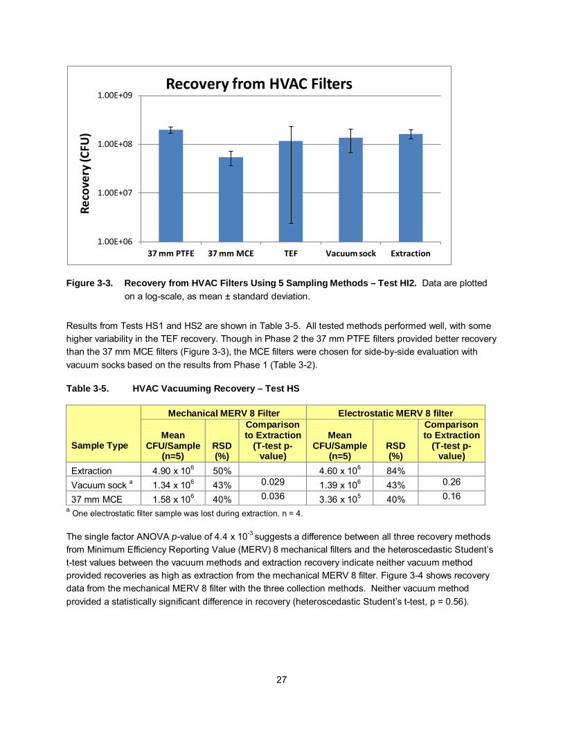
27
Figure 3-3. Recovery from HVAC Filters Using 5 Sampling Methods – Test HI2. Data are plotted on a log-scale, as mean ± standard deviation.
Results from Tests HS1 and HS2 are shown in Table 3-5. All tested methods performed well, with some higher variability in the TEF recovery. Though in Phase 2 the 37 mm PTFE filters provided better recovery than the 37 mm MCE filters (Figure 3-3), the MCE filters were chosen for side-by-side evaluation with vacuum socks based on the results from Phase 1 (Table 3-2).
Table 3-5. HVAC Vacuuming Recovery – Test HS
Sample Type
Mechanical MERV 8 Filter Electrostatic MERV 8 filter
Mean CFU/Sample
(n=5) RSD (%)
Comparison to Extraction
(T-test p-value)
Mean CFU/Sample
(n=5) RSD (%)
Comparison to Extraction
(T-test p-value)
Extraction 4.90 x 10⁶ 50% 4.60 x 10⁶ 84%
Vacuum sock a 1.34 x 10⁶ 43% 0.029 1.39 x 10⁶ 43% 0.26
37 mm MCE 1.58 x 10⁶ 40% 0.036 3.36 x 10⁵ 40% 0.16 a One electrostatic filter sample was lost during extraction. n = 4.
The single factor ANOVA p-value of 4.4 x 10⁻³ suggests a difference between all three recovery methods
from Minimum Efficiency Reporting Value (MERV) 8 mechanical filters and the heteroscedastic Student’s t-test values between the vacuum methods and extraction recovery indicate neither vacuum method provided recoveries as high as extraction from the mechanical MERV 8 filter. Figure 3-4 shows recovery data from the mechanical MERV 8 filter with the three collection methods. Neither vacuum method provided a statistically significant difference in recovery (heteroscedastic Student’s t-test, p = 0.56).
1.00E+06
1.00E+07
1.00E+08
1.00E+09
37 mm PTFE 37 mm MCE TEF Vacuum sock Extraction
Reco
very
(CFU
) Recovery from HVAC Filters
28
Figure 3-4. Recovery from Mechanical MERV 8 Filter – Test HS. Data are plotted on a log-scale, as mean ± standard deviation.
Unlike the case for mechanical type filters, the single factor ANOVA suggests no statistical difference between all three recovery methods from electrostatic MERV 8 filters (p = 0.16) (Figure 3-5). However, reanalysis using log10-transformed recovery, thus stabilizing variability, indicates there is a statistically significant difference between the three methods (ANOVA, p = 0.002). This difference is indicative in part to a high uncertainty in the number of spores deposited. Table 3-6 shows the heteroscedastic Student’s t-test between method pairs for both raw recovery and log-transformed recovery.
Table 3-6. Student’s t-test values from Electrostatic filters
Method Pairs
Heteroscedastic Student’s T-test p-values
Recovery Log10 Recovery
vacuum sock vs. 37 mm 0.036147 0.005965
vacuum sock vs. extraction 0.262986 0.187705
37 mm vs. extraction 0.157613 0.007319
Table 3-6 suggests a statistically significant difference between vacuum sock and 37 mm MCE vacuum methods, indicating higher recovery from vacuum sock. Table 3-6 also suggests a potential difference between 37 mm and extraction methods.
1.00E+04
1.00E+05
1.00E+06
1.00E+07
Vacuum sock HVAC Extraction 37 mm MCE
Reco
very
(CFU
) Recovery from Mechanical MERV 8 HVAC Filters

29
Figure 3-5. Recovery from Electrostatic HVAC Filter – Test HS. Data are plotted on a log scale, as
mean ± standard deviation.
The vacuum sock method was much easier to perform on HVAC filters than the operation of the 37 mm filters. However, the ease of performance may be true only for certain types of HVAC filters. Filter types with very deep crevices may require a sampling method such as the 37 mm filter method, which uses a more narrow nozzle. The Phase 2 test matrix also included comparisons of recovery methods from stainless steel deposition. While these depositions were in part included for quality control − as a measure of the stability of the inoculation MDI − they also provide information on spore recovery from nonporous surfaces. These data are not directly comparable to the HVAC data, due to the spores that passed completely through the filter as discussed above (Test HI1). Tables 3-7 and 3-8 summarize the recovery results from stainless steel surface samples, collected and analyzed during Phase 2 tests. The data are segregated by test because different MDIs were used for each. But taken collectively, the three recovery methods were equivalent, with no method producing statistically significant higher recovery.
1.00E+04
1.00E+05
1.00E+06
1.00E+07
1.00E+08
Vacuum sock HVAC Extraction 37 mm MCE
Reco
very
(CFU
) Recovery from Electrostatic MERV 8 Filters

30
Table 3-7. Mean Recovery from Stainless Steel Coupons (n = 3), Phase 2 Tests
Sampling Method Log10 CFU (± Standard Deviation)
HS2 HS1b HS1
extraction 2.2 x 10⁷ (6.61 x 10⁶) 1.75 x 10⁷ (5.23 x 10⁶) 1.11 x 10⁸ (2.68 x 10⁷)
sponge-wipe 2.63 x 10⁷ (8.8 x 10⁶) 1.90 x 10⁷ (6.61 x 10⁶) 7.52 x 10⁷ (2.10 x 10⁷)
PRB wipes 1.93 x 10⁷ (3.02 x 10⁶) 2.05 x 10⁷ (5.11 x 10⁶) NA Note: Standard deviation is in parentheses.
Table 3-8. ANOVA – Comparison of the Three Stainless Steel Recovery Methods within each Phase 2 Test Run (n = 3)
Test Source of Variation df F P-value F crit
HS2 Between Groupsa 2 0.87 0.46 5.14
HS1b Between Groups 2 0.20 0.82 5.14
HS1 Between Groups 2 3.21 0.15 7.71
a Groups: Direct extraction, sponge-wipe, and PRB wipe of stainless steel. 3.3 Phase 3 The results from the INOC test series are summarized in Table 3-9 and graphically displayed in Figure 3-6.
Table 3-9. Mean Recoveries from Stainless Steel using the Sponge-wipe Method - Test INOC (n = 10)
MDI (Target Dose)
103 104 107
Mean Recovery (CFU) 1.27 x 10³ 1.48 x 10⁴ 1.39 x 10⁷ RSD 37% 31% 52%

31
Figure 3-6. Recovery from Stainless Coupons during INOC Series Tests.
These results demonstrate the ability of both the deposition method and the sponge-wipe recovery method over a range of spore concentrations. This approach was then applied to carpet coupons so that vacuum-based methods could be evaluated over a range of spore concentrations. The mean recoveries (CFU) for each vacuum-based method are shown in Table 3-10 and Figure 3-7. These data were gathered to evaluate the linearity of recoveries by each method when challenged with inocula spanning several orders of magnitude.
Table 3-10. Mean Recoveries (CFU/sample) from Test LR (n=5)
Mean Recoveries (CFU/sample)
Inoculation Level Vacuum Sock
(Carpet) 37 mm MCE
(Carpet) Extraction
(Stainless Steel) Sponge-wipe
(Stainless Steel) 104 1.06 x 10³ 2.48 x 10³ 1.60 x 10⁴ 1.27 x 10⁴ 106 2.02 x 10⁵ 5.07 x 10⁵ 1.93 x 10⁶ 1.81 x 10⁶ 107 2.45 x 10⁶ 8.65 x 10⁶ 2.27 x 10⁷ 1.69 x 10⁷
1.00E+02
1.00E+03
1.00E+04
1.00E+05
1.00E+06
1.00E+07
1.00E+08
1 2 3 4 5 6 7 8 9 10
Reco
very
(CFU
)
Replicate
Recovery from Stainless Coupons
E3
E4
E7

32
Figure 3-7. Mean CFU/Sample from Linear Recovery (LR) Test. Data are plotted on a log-scale as mean ± standard deviation.
Table 3-11 shows the relative recovery (percentage) based on stainless steel extraction method.
Table 3-11. Percent Relative Recovery of Vacuum Devices (Test LR) (n = 5)
Target Inoculum
Relative Recovery
(percent of stainless steel extraction recovery)
Mean Relative Recovery
(percent of stainless steel extraction recovery)
Vacuum Sock 37 mm MCE Vacuum Sock 37 mm MCE
104
4% 30%
7% 15% 14% 12% 3% 3% 7% 11% 6% 21%
106
11% 21%
10% 26% 7% 15%
16% 19% 9% 51%
10% 25%
107
12% 35%
11% 38% 11% 104% 16% 20% 9% 9% 6% 22%
1.00E+00
1.00E+01
1.00E+02
1.00E+03
1.00E+04
1.00E+05
1.00E+06
1.00E+07
1.00E+08
E4 E6 E7
Reco
ver (
CFU
) Linear Recovery Test
Vacuum sock
37 mm MCE

33
The relative recovery (RR%) consists of the mean recovery (CFU) from each vacuum sample divided by the mean recovery (CFU) from sponge-wipe sampling stainless steel (Table 3-12). These data suggest a slight advantage of the 37 mm MCE vacuum method over the vacuum sock method, though the Student t-test returned p-values ≥ 0.05 for each comparison.
Table 3-12. Relative Recovery of Vacuum Methods to Sponge-Wipe – Test LR (n=5).
Target Inoculum
Relative Recovery
(percent of sponge-wipe recovery)
Mean Relative Recovery
(percent of sponge-wipe recovery)
Vacuum Sock 37 mm MCE Vacuum Sock 37 mm MCE
104
5% 38%
8.3% 19.6% 17% 15% 3% 4% 8% 14% 8% 27%
106
12% 22%
11.1% 28.0% 7% 16%
17% 21% 9% 54%
11% 27%
107
17% 47%
14.5% 51.2% 14% 140%1 22% 27% 12% 12% 8% 30%
1 – Data point is within two standard deviations about the mean and the value was therefore not considered an outlier.
ANOVA analysis of CR% over the three inoculums suggested that there was no difference in the recovery over the entire range for either vacuum method. (i.e., no statistical difference in CR% between devices at each inoculum)
Results from Test LV showing variation in laboratory and personnel for two vacuum methods are shown in Figure 3-8 and Table 3-13.

34
Figure 3-8. Laboratory Variability for Two Vacuum Methods - Test LV
Table 3-13. Laboratory Variability for Two Vacuum Methods (Test LV)
Average CFU/Sample % Recovery of Extraction Controls
Sample Type n Lab 1 Lab 2 Lab 1 Lab 2
37 mm MCE 10 3.58 x 10⁶ 4.12 x 10⁶ 12.4 % 13.7 %
Vacuum Sock 10 2.01 x 10⁶ 2.47 x 10⁶ 6.8% 8.4%
Standard Deviation Standard Deviation Sample Type n Lab 1 Lab 2 Lab 1 Lab 2
37 mm MCE 10 1.34 x 10⁶ 1.25 x 10⁶ 4.6 % 4.6%
Vacuum Sock 10 1.06 x 10⁶ 4.86 x 10⁵ 3.7 % 1.7%
CV% CV%
Sample Type n Lab 1 Lab 2 Lab 1 Lab 2
37 mm MCE 10 37% 34% 37% 34%
Vacuum Sock 10 53% 20% 53% 20%
T-Test Between Laboratories T-Test Between Laboratories
Sample Type n
37 mm MCE 10 0.522 0.522
Vacuum Sock 10 0.234 0.234
There was no statistically significant difference between the recoveries of the two laboratories. Pooling the results of the two laboratories, however, does show a significant difference between the results of the two vacuum methods, with a Student’s t-test value of 4.9 x 10⁻⁵. With this large number of replicates, the 37 mm MCE vacuum method did provide better recovery than the vacuum sock method.
1.00E+05
1.10E+06
2.10E+06
3.10E+06
4.10E+06
5.10E+06
6.10E+06
7.10E+06
37 mm MCE Vacuum Sock
Reco
very
(CFU
) Laboratory Variability
Lab 1
Lab 2

35
4 Quality Assurance
This project was performed under an approved Category III QAPP titled Evaluation of Vacuum-based Sampling Devices for Collection of Biological Agent (DCMD 3.60) (October 2011).
4.1 Sampling, Monitoring, and Analysis Equipment Calibration There were SOPs for the maintenance and calibration of all laboratory and NHSRC Microbiology Laboratory equipment. All equipment was verified as being certified calibrated or having the calibration validated by EPA’s APPCD on-site (RTP, NC) Metrology Laboratory at the time of use. Standard laboratory equipment such as balances, pH meters, biological safety cabinets and incubators were routinely monitored for proper performance. Calibration of instruments was done at the frequency shown in Table 4-1. Any deficiencies were noted. The instrument was adjusted to meet calibration tolerances and recalibrated within 24 h. If tolerances were not met after recalibration, additional corrective action was taken, possibly including recalibration or/and replacement of the equipment.
Table 4-1. Sampling and Monitoring Equipment Calibration Frequency
Equipment Calibration/Certification Expected Tolerance Thermometer Compare to independent NIST thermometer (this is
a thermometer that is recertified annually by either NIST or an International Organization for Standardization (ISO)-17025 facility) value once per quarter
±1°C
Stopwatch Compare against NIST Official U.S. time at http://nist.time.gov/timezone.cgi?Eastern/d/-5/java once every 30 days.
±1 min/30 days
Clock Compare to office U.S. Time @ time.gov every 30 days.
±1 min/30 days
Micropipets All micropipets will be certified as calibrated at time of use. Pipettes are recalibrated by gravimetric evaluation of pipette performance to manufacturer's specifications every year.
±5%
Scale Compare reading to Class S weights ±1%

36
4.2 Data Quality The primary objective of this project was to evaluate up to four currently-available vacuum-based devices for biological sampling efficiency. Performance (recovery) of devices was compared to the currently-preferred method, the "Vacuum Sock" (Midwest Filtration; Cincinnati, OH). Evaluation of operational parameters included time required for sample collection, the physical impact on the sampling team during collection, time required for sample analysis, and the cost of media and analysis equipment and supplies. This section discusses the Quality Assurance/Quality Control (QA/QC) checks (Section 4.3) and Acceptance Criteria for Critical Measurements (Section 4.4) considered critical to accomplishing the project objectives.
4.3 QA/QC Checks Uniformity of the test materials was a critical attribute to ensuring reliable test results. Uniformity was maintained by obtaining a large enough quantity of material so that multiple material sections and coupons could be constructed with presumably uniform characteristics. Samples and test chemicals were maintained to ensure their integrity. Samples were stored away from standards or other samples which could cross-contaminate them.
Supplies and consumables were acquired from reputable sources and were National Institute of Standards and Technology (NIST)-traceable when possible. Supplies and consumables were examined for evidence of tampering or damage upon receipt and prior to use, as appropriate. Supplies and consumables showing evidence of tampering or damage were not used. All examinations were documented and supplies were appropriately labeled. Project personnel checked supplies and consumables prior to use to verify that they met specified task quality objectives and did not exceed expiration dates.
Quantitative standards do not exist for biological agents. Quantitative determinations of organisms in this investigation did not involve the use of analytical measurement devices. Rather, the CFU were enumerated manually and recorded. QC checks for critical measurements/parameters are shown in Table 4-2. These checks also served as DQI goals. The acceptance criteria were set at the most stringent level that could be routinely achieved and are consistent with the DQOs described in Section 4.4. Positive controls and procedural blanks were included along with the test samples in the experiments so that well-controlled quantitative values were obtained. Verification of the sterility of samples prior to inoculation and other background checks were also included as part of the standard protocol. Replicate coupons were included for each set of test conditions. MOPs using qualified, trained and experienced personnel were used to ensure data collection consistency. The confirmation procedure, controls, blanks, and method validation efforts were the basis of support for biological investigation results. If necessary, training sessions were conducted by knowledgeable parties, and in-house practice runs were used to gain expertise and proficiency prior to initiating the research.
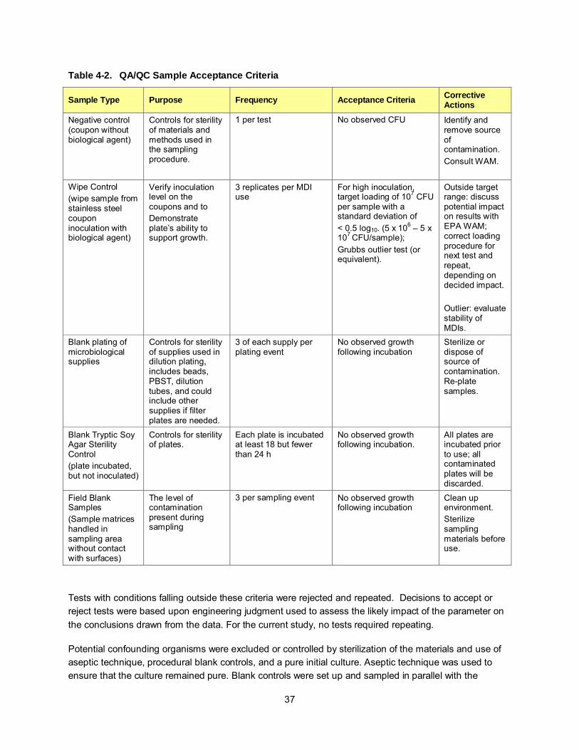
37
Table 4-2. QA/QC Sample Acceptance Criteria
Sample Type Purpose Frequency Acceptance Criteria Corrective Actions
Negative control (coupon without biological agent)
Controls for sterility of materials and methods used in the sampling procedure.
1 per test No observed CFU
Identify and remove source of contamination. Consult WAM.
Wipe Control (wipe sample from stainless steel coupon inoculation with biological agent)
Verify inoculation level on the coupons and to Demonstrate plate’s ability to support growth.
3 replicates per MDI use
For high inoculation, target loading of 107 CFU per sample with a standard deviation of < 0.5 log10. (5 x 10⁶ – 5 x 10⁷ CFU/sample); Grubbs outlier test (or equivalent).
Outside target range: discuss potential impact on results with EPA WAM; correct loading procedure for next test and repeat, depending on decided impact. Outlier: evaluate stability of MDIs.
Blank plating of microbiological supplies
Controls for sterility of supplies used in dilution plating, includes beads, PBST, dilution tubes, and could include other supplies if filter plates are needed.
3 of each supply per plating event
No observed growth following incubation
Sterilize or dispose of source of contamination. Re-plate samples.
Blank Tryptic Soy Agar Sterility Control (plate incubated, but not inoculated)
Controls for sterility of plates.
Each plate is incubated at least 18 but fewer than 24 h
No observed growth following incubation.
All plates are incubated prior to use; all contaminated plates will be discarded.
Field Blank Samples (Sample matrices handled in sampling area without contact with surfaces)
The level of contamination present during sampling
3 per sampling event No observed growth following incubation
Clean up environment. Sterilize sampling materials before use.
Tests with conditions falling outside these criteria were rejected and repeated. Decisions to accept or reject tests were based upon engineering judgment used to assess the likely impact of the parameter on the conclusions drawn from the data. For the current study, no tests required repeating.
Potential confounding organisms were excluded or controlled by sterilization of the materials and use of aseptic technique, procedural blank controls, and a pure initial culture. Aseptic technique was used to ensure that the culture remained pure. Blank controls were set up and sampled in parallel with the

38
contaminated materials. Infrequently, colonies were observed from negative control and procedural blank samples. The magnitude of the recoveries from these samples was always at least 2 orders of magnitude lower than test samples, and therefore did not significantly affect results.
4.4 Acceptance Criteria for Critical Measurements The DQOs are used to determine the CMs needed to address the stated objectives and specify tolerable levels of potential errors associated with simulating the prescribed decontamination environments. The following measurements were deemed to be critical to accomplish part or all of the project objectives:
• Enumeration of spores recovered from the surface of the coupons. • Total number of coupons vacuumed per sample.
The DQIs listed in Table 4-3 are specific criteria used to quantify how well the collected data met the DQOs. Failure to provide a measurement method or device that meets these goals results in the rejection of results derived from the CM. For instance, if the plated volume of a sample is not known (i.e., is not 100% complete), then that sample is invalid.
Table 4-3. Critical Measurement Acceptance Criteria
Critical Measurement
Measurement Device Accuracy Precision Detection
Limit Completeness
Plated Volume Pipet ±2% ±1% NA 100%
CFU/Plate Enumeration by visual
inspection
±10% (between 2 counters)
±5 1 CFU 100%
Number of coupons per plate
Enumeration by visual
inspection
±1% ±0.5 1 100%
Plated volume critical measurement goals were met. All pipets are calibrated yearly by an outside contractor (Calibrate, Inc., Carborro, NC) and verified gravimetrically at the conclusion of testing.
Plates were analyzed quantitatively (CFU/plate) using a visual inspection-based counting method. For each set of results (per test), a second enumeration was performed on 25 percent of the plates within the desirable range (30-300 CFU per plate). All second counts were found to be within 10 percent of the original count.
There are many QA/QC checks used to validate microbiological measurements. These checks include samples that demonstrate the ability of the NHSRC Microbiology Laboratory to culture the test organism, as well as to demonstrate that materials used in this effort do not themselves contain spores. The checks include:

39
• Field blank coupons: sterile coupons sampled at the same time as inoculated coupons.
• Field blank sample: vacuum-based sampling media attached to vacuum device, and device was
activated for one minute. Unfiltered laboratory air was collected, no surfaces were sampled.
• Laboratory material coupons: includes all materials, individually, used by the NHSRC Microbiology
Laboratory in sample analysis.
• Inoculation control coupons: stainless steel coupons inoculated at beginning, middle, and end of each
inoculation campaign. After 18 – 24 h, surfaces were sampled with PRB wipes and analyzed to
assess the precision and accuracy of the MDI during the inoculation operation.
4.5 Data Quality Audits This project was assigned QA Category III and did not require technical systems or performance evaluation audits.
4.6 QA/QC Reporting QA/QC procedures were performed in accordance with the QAPP for this investigation.

40
5 Summary
5.1 Phase 1 Four vacuum methods (vacuum sock, 37 mm MCE filter, 37 mm PTFE filter, and TEF), were evaluated for sampling porous materials (concrete, carpet, and upholstery). The vacuum sock method was tested additionally at two sampling speeds. The vacuum sock and TEF method afforded more ease of use to those collecting the samples and may therefore be more desirable for larger sample areas. However, the 37 MCE filter method demonstrated higher recoveries per unit area than did the vacuum sock device. The TEF and vacuum sock (slow) method performed poorly on upholstery. The TEF also performed poorly on carpet. There are advantages and disadvantages for each device.
Some conclusions can be reached based on Phase 1 recovery:
• the speed of vacuum sock sampling (rate of speed the vacuum device traversed the coupon
surface) does not necessarily impact collection; and
• overall recovery (including collection from the surface, retention on the filter, then extraction from
the filter) of spores using the 37 mm MCE vacuum method was often higher than the recovery
achieved from the other devices.
5.2 Phase 2 A method was developed which successfully deposited spores on (and through) HVAC filters under flow conditions. Three methods of sampling HVAC filters (two vacuum methods and one extractive) performed reliably on mechanical and electrostatic filters. The data suggest extractive methods may be more efficient than vacuum-based recovery methods, depending on filter type. Vacuum sock sampling provided higher recovery from mechanical filters, but both sock and 37 mm cassettes performed similarly when sampling from electrostatic filters. Vacuum-based methods may be more applicable to HVAC filter media that are not easily sectioned.
Phase 2 data also suggested there was no statistical difference between extraction, sponge-wipes, or PRB wipes for recovery from stainless steel coupons.
5.3 Phase 3 The MDI inoculation method and the sponge-wipe recovery method were demonstrated to be effective over a broad range of concentrations, from 1 to 1 × 10⁴ CFU/cm2 (1 x 10³ to 1x10⁷ CFU/sample). Two vacuum methods were also demonstrated effective over the same range. Compared to sponge-wipes (from stainless steel), the vacuum sock method demonstrated recoveries between 3% and 22%, while the 37 mm MCE filter method demonstrated recoveries between 4% and 140% from carpet samples. The extraction procedures for both vacuum methods were evaluated by two independent laboratory technicians with no statistical difference in the number of spores recovered.
5.4 Lessons Learned and Application of Vacuum-based Methods to Field Use Based on the data generated during this study, the 37 mm MCE and the vacuum sock sampling methods were most efficient among the combination of materials and vacuum-based methods evaluated. When

41
looking at these methods from an operational perspective, the vacuum sock and trace evidence filter methods offer advantages in that they allow a greater amount of surface area to be sampled in a given amount of time. Increasing the amount of area sampled increases the representativeness of the sample. Collecting samples more rapidly decreases the sampler’s time down range (in the contaminated area), resulting in decreasing health and safety-related risks. However, each method has a unique set of advantages and disadvantages. Table 5-1 below summarizes these advantages and disadvantages.
Table 5-1. Summary of Advantages and Disadvantages of Each Vacuum-Based Sampling Method.
37 mm (MCE or PTFE) Vacuum Sock Trace Evidence Filter
Advantages Disadvantages Advantages Disadvantages Advantages Disadvantages
High collection
efficiency for
some surfaces
(i.e., concrete
and upholstery)
AC power required
for the Vac-U-Go
SKC sampling pump
(SKC, Inc.)
Larger surface
area collected
AC power required;
however, newer Omega
vacuum (Global
Industrial, Port
Washington, NY) comes
with battery option
Larger surface
area collected
AC power required;
however, newer
Omega vacuum
comes with battery
option
Sample is
easily contained
and packaged
following
collection
Long sample
collection time, >5
min per 1 ft2
Short sample
collection time:
1.5 to 4 min per 1
ft2
Heavy equipment,
cumbersome in the field
Short sample
collection time:
2 min per 1 ft2
Volumetric flow
above 790 L min-1
will cause filter to
unseat from base,
allowing air to
bypass filter
Relatively
simple
extraction
procedure
Increases health and
safety concerns due
to longer sampling
duration required for
a given number of
samples
Vacuum housing
can be
decontaminated
by wiping
Poor quality control in
device construction
(some have visible holes
in the seams)
Vacuum
housing can be
decontaminate
d by wiping
Expensive (~$20
per sample device)
Shortest time
requirement of
the methods
evaluated for
laboratory
extraction
Sample is
easily
contained and
packaged
following
sample
collection
Longest time
requirement of
methods evaluated
for laboratory
extraction
In summary, all three methods are available and could be utilized during a large-scale event. The results of the current study suggest the 37 mm and vacuum sock methods perform well and with less variability than the TEF. When selecting a sampling method for nonporous surfaces, the method should be based on sampling efficiency, portability, sampling time, surface area sampled, and health and safety of sampling personnel.

42
5.5 Future Research Future research efforts may focus on improving the 37 mm filter cassette sampling method. These improvements could involve increasing the sampling speed of the 37 mm MCE collection to determine the effect of sampling speed. Alternatively, the width of the 37 mm nozzle could be increased while maintaining the cross-sectional area of the nozzle. Further testing would need to be conducted to determine the effect of this nozzle alteration.
More testing should be conducted on a variety of HVAC filters to vet the methods more thoroughly. In addition, further study is needed to investigate the effect of surface grime or conditions on recovery.

43
References
1. Brown, G.S., R.G. Betty, J.E. Brockmann, D.A. Lucero, C.A. Souza, K.S. Walsh, R.M. Boucher, M.S. Tezak,
and M.C. Wilson, Evaluation of vacuum filter sock surface sample collection method for Bacillus spores from
porous and non-porous surfaces. Journal of Environmental Monitoring, 2007. 9(7): p. 666-671.
2. Frawley, D.A., M.N. Samaan, R.L. Bull, J.M. Robertson, A.J. Mateczun, and P.C.B. Turnbull, Recovery
efficiencies of anthrax spores and ricin from nonporous or nonabsorbent and porous or absorbent surfaces
by a variety of sampling methods. Journal of Forensic Sciences, 2008. 53(5): p. 1102-1107.
3. Estill, C.F., P.A. Baron, J.K. Beard, M.J. Hein, L.D. Larsen, L. Rose, F.W. Schaefer, 3rd, J. Noble-Wang, L.
Hodges, H.D. Lindquist, G.J. Deye, and M.J. Arduino, Recovery efficiency and limit of detection of
aerosolized Bacillus anthracis Sterne from environmental surface samples. Applied and Environmental
Microbiology, 2009. 75(13): p. 4297-306.
4. Baron, P.A., C.F. Estill, J.K. Beard, M.J. Hein, and L. Larsen, Bacterial endospore inactivation caused by
outgassing of vapourous hydrogen peroxide from polymethyl methacrylate (Plexiglas®). Letters in Applied
Microbiology, 2007. 45(5): p. 485-490.
5. Brown, G.S., R.G. Betty, J.E. Brockmann, D.A. Lucero, C.A. Souza, K.S. Walsh, R.M. Boucher, M. Tezak,
M.C. Wilson, and T. Rudolph, Evaluation of a wipe surface sample method for collection of bacillus spores
from nonporous surfaces. Applied and Environmental Microbiology, 2007. 73(3): p. 706-710.
6. Calfee, M.W., S.D. Lee, and S.P. Ryan, A rapid and repeatable method to deposit bioaerosols on material
surfaces. Journal of Microbiological Methods, 2013. 92(3): p. 375-80.
7. Busher, A., J. Noble-Wang, and L. Rose, Sampling for Biological Agents in the Environment, P. Emanual,
Roos, J.W.,Niyogi,K., Editor. 2008, ASM Press: Washington, DC,. p. pp 95-131.
8. Rose, L.J., L. Hodges, H. O'Connell, and J. Noble-Wang, National validation study of a cellulose sponge
wipe-processing method for use after sampling Bacillus anthracis spores from surfaces. Applied
Environmental Microbiology, 2011. 77(23): p. 8355-9.

44
Appendix A: Miscellaneous Operating Procedures
MOP 3135 Procedure for Sample Collection using BactiSwabTM Collection and Transport Systems
MOP 3144 Procedure for Wipe Sampling of Coupons
MOP 3145 Procedure for Vacuum Sock Sampling of Large and Small Coupons
MOP 3161-F Aerosol Deposition of Spores on HVAC Filter Under Flow
MOP 3161-HD Aerosol Deposition of Spores onto Material Coupon Surfaces Using The Aerosol Deposition Apparatus (ADA) – High Dosing
MOP 3161-LD Aerosol Deposition of Spores onto Material Coupon Surfaces Using The Aerosol Deposition Apparatus (ADA) – Low Dosing
MOP 3164 Procedure for 37MM Cassette and Trace Evidence Filter Vacuum Sampling of Large and Small Coupons
MOP 3165 Sponge Sample Collection Protocol
MOP 3168 Aggressive Air Sampling (AAS) for WA 3-28: Phase 1 Sampling Approach
MOP 6535a Serial Dilution: Spread Plate Procedure to Quantify Viable Bacterial Spore
MOP 6555: Petri Dish Media Inoculation Using Beads
MOP 6562 Preparing Pre-Measured Tubes with Aliquotted Amounts of Phosphate Buffered Saline with Tween 20 (PBST)
MOP 6563 Swab Streak Sampling and Analysis
MOP 6565 Filtration and Plating of Bacteria from Liquid Extracts MOP 6567 Recovery of Bacillus Spores from Wipe Samples
MOP 6570 Use of STERIS Amsco Century SV 120 Scientific Pre-vacuum Sterilizer
MOP 6572 Recovery of Spores from Vacuum Sock Samples
MOP 6579 Recovery of Bacillus Spores from 37MM Filter Cassettes
MOP 6580 Recovery of Bacillus Spores from 3M Sponge-Stick™ Samples
MOP 6582 Recovery of Bacillus Spores from Trace Evidence Filters
MOP 6586 Recovery of Bacillus Spores from Quartz Filters
MOP 6593 Recovery of Spores from HVAC Filters

Appendix B: Miscellaneous Operating Procedures
MOP 3135 Procedure for Sample Collection using BactiSwabTM Collection and Transport Systems
MOP 3144 Procedure for Wipe Sampling of Coupons
MOP 3145 Procedure for Vacuum Sock Sampling of Large and Small Coupons
MOP 3161-F Aerosol Deposition of Spores on HVAC Filter Under Flow
MOP 3161-HD Aerosol Deposition of Spores onto Material Coupon Surfaces Using The Aerosol Deposition Apparatus (ADA) – High Dosing
MOP 3161-LD Aerosol Deposition of Spores onto Material Coupon Surfaces Using The Aerosol Deposition Apparatus (ADA) – Low Dosing
MOP 3164 Procedure for 37MM Cassette and Trace Evidence Filter Vacuum Sampling of Large and Small Coupons
MOP 3165 Sponge Sample Collection Protocol
MOP 3168 Aggressive Air Sampling (AAS) for WA 3-28: Phase I Sampling Approach
MOP 6535a Serial Dilution: Spread Plate Procedure to Quantify Viable Bacterial Spore
MOP 6555: Petri Dish Media Inoculation Using Beads
MOP 6562 Preparing Pre-Measured Tubes with Aliquoted Amounts of Phosphate Buffered Saline with Tween 20 (PBST)
MOP 6563 Swab Streak Sampling and Analysis
MOP 6565 Filtration and Plating of Bacteria from Liquid Extracts MOP 6567 Recovery of Bacillus Spores from Wipe Samples
MOP 6570 Use of STERIS Amsco Century SV 120 Scientific Prevacuum Sterilizer
MOP 6572 Recovery of Spores from Vacuum Sock Samples
MOP 6579 Recovery of Bacillus Spores from 37MM Filter Casettes
MOP 6580 Recovery of Bacillus Spores from 3M Sponge-Stick™ Samples
MOP 6582 Recovery of Bacillus Spores from Trace Evidence Filters
MOP 6586 Recovery of Bacillus Spores from Quartz Filters
MOP 6593 Recovery of Spores from HVAC Filters

MOP-3135Revision 2
November 2012Page 1 of 3
Miscellaneous Operating Procedure (MOP) 3135:
Procedure for Sample Collection Using BactiSwabTM
Collection and Transport Systems
Prepared by: __________________________________________ Date: 11/15/2012Stella McDonald, ARCADIS Work Assignment Leader
Reviewed by: __________________________________________ Date: 11/15/2012Dahman Touati, ARCADIS Project Manager
Approved by: __________________________________________ Date: 11/15/2012Worth Calfee, EPA Work Assignment Manager
Prepared for
National Homeland Security Research CenterOffice of Research and Development
U.S. Environmental Protection AgencyResearch Triangle Park, NC 27711
Prepared by
ARCADIS U.S., Inc.4915 Prospectus Drive, Suite F
Durham, NC 27713

MOP-3135Revision 2
November 2012Page 2 of 3
MOP 3135
TITLE: Procedure for Sample Collection using BactiSwabTM Collection and TransportSystems
SCOPE: This MOP describes the procedure for collecting swab samples for Low TechDecontamination Technique Testing
PURPOSE: The purpose if this MOP is to ensure all swab sampling is performed in aconsistent manner.
Equipment/Reagents
Disposable lab coat
Nitrile examination gloves
P95 Respirator
Shoe covers
Bouffant cap
Safety glasses
BactiSwabTM Collection and Transport System
1.0 PROCEDURE
1. Before starting the swabbing procedure, make sure you are wearing the appropriate, project-specific PPE (at a minimum gloves, lab coat, and safety glasses).
2. Through the sleeve, crush the BactiSwabTM ampule at midpoint.
3. Hold BactiSwabTM tip end up for at least five seconds to allow the medium to wet the swab.
4. Open the package and remove the BactiSwabTM.
5. Label the plastic tube appropriately using the following scheme:
X-Y-N where,
X is the test number,Y is the material abbreviation, andN is the material number
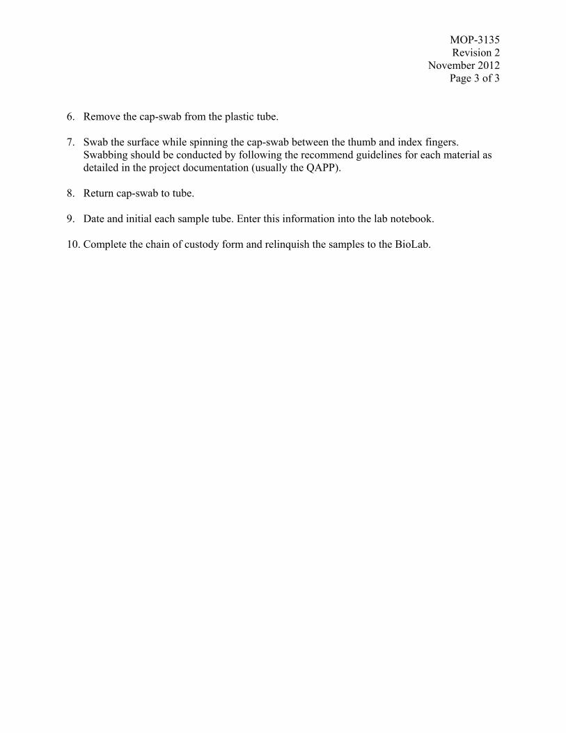
MOP-3135Revision 2
November 2012Page 3 of 3
6. Remove the cap-swab from the plastic tube.
7. Swab the surface while spinning the cap-swab between the thumb and index fingers.Swabbing should be conducted by following the recommend guidelines for each material asdetailed in the project documentation (usually the QAPP).
8. Return cap-swab to tube.
9. Date and initial each sample tube. Enter this information into the lab notebook.
10. Complete the chain of custody form and relinquish the samples to the BioLab.

MOP-3144Revision 2
November 2012Page 1 of 7
Miscellaneous Operating Procedure (MOP) 3144:
Procedures for Wipe Sampling of Coupons
Prepared by: __________________________________________ Date: 11/15/2012Stella McDonald, ARCADIS Work Assignment Leader
Reviewed by: __________________________________________ Date: 11/15/2012Dahman Touati, ARCADIS Project Manager
Approved by: __________________________________________ Date: 11/15/2012Worth Calfee, EPA Work Assignment Manager
Prepared for
National Homeland Security Research CenterOffice of Research and Development
U.S. Environmental Protection AgencyResearch Triangle Park, NC 27711
Prepared by
ARCADIS U.S., Inc.4915 Prospectus Drive, Suite F
Durham, NC 27713

MOP-3144Revision 2
November 2012Page 2 of 7
MOP-3144
TITLE: PROCEDURE FOR WIPE SAMPLING OF COUPONS
SCOPE: This MOP describes the procedure for wipe sampling both small and largecoupons.
PURPOSE: The purpose of this MOP is to ensure consistent and representative sampling ofsuch coupons.
EQUIPMENT (quantities are per sampling kit)
Sterile sampling bag (10” x 14”) – outer bag
Sterile sampling bag (5.5” x 9 “) – inner “sample collection sterile sampling bag”
Two sterile 50 mL Falcon Blue-Max™ Polypropylene Conical Tubes
Sterile Kendall (ref. # 8402) 4-ply all-purpose sponge
Sterile phosphate buffered saline with 0.005% TWEEN®-20, prepared according toMOP -6562
Pipette or other method for aseptic dispensing of 5 mL liquid
Sterile Posi-grip© forceps
P-95 Particulate Respirators – to prevent contamination and for respiratory protection.(Specific projects may require additional respiratory protection and will be addressed inthe project Quality Assurance Project Plan (QAPP), e.g, SAR)
Powder-free Nitrile gloves (support person) and Kimtech Pure G3 Sterile Nitrile gloves(sampler)
Dispatch® bleach wipes
1.0 PREPARATION
1. All materials needed for collection of each sample will be prepared in advance using aseptictechnique. A sample kit for a single wipe sample will be prepared as follows:
a. Two sterile sampling bags (10” x 14”, 5.5” x 9 “) and a 50 mL conical tube, capped,will be uniquely labeled as specified in the project QAPP. These bags and conicaltube will have the same label. The 5.5” x 9” labeled sterile sampling bag will bereferred to as the sample collection sampling bag.
b. A sterile all-purpose sponge will be placed in an unlabeled sterile 50 mL conical tubeusing sterile forceps and aseptic technique. The all-purpose sponge will be moistened

MOP-3144Revision 2
November 2012Page 3 of 7
by adding 2.5 mL of sterile phosphate buffered saline with 0.005% TWEEN®-20.The tube will then be capped.
c. The labeled 50 mL conical tube (capped), the unlabeled conical tube containing thepre-moistened all-purpose sponge, and the 5.5” x 9” labeled sampling bag will beplaced into the 10” x 14” labeled sampling bag. Hence, each labeled sampling bagwill contain a labeled 50 mL conical tube (capped), an unlabeled capped conical tubecontaining a pre-moistened all-purpose sponge, and an empty labeled sampling bag.
d. Each prepared bag is one sampling kit.
2.0 SAMPLING PROCEDURE FOR SMALL 14”x14” COUPONS
1. A three person team will be used, employing aseptic technique throughout. The team willconsist of a sampler, sample handler, and support person.
2. Throughout the procedure, the support person will log anything they deem to be significantinto the laboratory notebook.
3. In general, the team works from the least contaminated sample set (i.e., control blanks)towards the most contaminated sample set (i.e., positive controls).
4. The sampling team will each don a pair of sampling gloves (a new pair per sample, non-sterile, as they will only be handling non-sterile items); the sampler’s gloves shall be sterilesampling gloves as they are the only member of the team in contact with the sample. Allmembers shall wear dust masks to further minimize potential contamination of the samples.Depending on the situation, respiratory protection beyond a dust mask may be required toprotect the sampling team (e.g., SAR; this will be specified in the project QAPP). Newdisposable lab coats are required for the sample handler when changing between differenttypes of materials or when direct contact between the coupon and lab coat occurs.
5. The sample handler will remove the coupon from the appropriate cabinet and place it on thesampling area, being careful to handle the coupon only around the edges.
6. The support person will record the coupon code on the sampling log sheet.
7. The support person will remove a template from the bag and aseptically unwrap it such thatthe sampler may grab it wearing sterile gloves.
8. The sampler will place the template onto the coupon surface and align it such that the edgesof the coupon are visible through the holes on the template.
9. The support person will remove a sample kit from the sampling bin and record the sampletube number on the sampling log sheet next to the corresponding coupon code just recorded.
10. The sampler and support person will verify the sample code and ensure that the correctcoupon and location are being sampled.
11. The support person will:
a. Open the outer sampling bag touching the outside of the bag.

MOP-3144Revision 2
November 2012Page 4 of 7
b. Touching only the outside of the (10” x 14”) bag, remove and open the unlabeledconical tube and pour the pre-moistened all-purpose sponge onto the sample or intothe sampler’s hands.
c. Discard the unlabeled conical tube.
d. Remove the sample collection sample bag (5.5” x 9”), being careful to not touch theinside of the outer sampling bag, and open it touching only the outside.
e. Maneuver the labeled 50 mL conical tube to the end of the outer sterile sampling bagand loosen the cap.
f. Remove the cap from 50 mL conical tube immediately preceding the introduction ofthe sample into the tube.
12. The sampler will:
a. Wipe the surface of the sample horizontally using S-strokes to cover the entire samplearea of the coupon using a consistent amount of pressure.
b. Fold the all-purpose sponge concealing the exposed side and then wipe the samesurface vertically using the same technique.
c. Fold the all-purpose sponge over again and roll up the folded sponge to fit into theconical tube.
d. Carefully place the all-purpose sponge into the 50 mL conical tube that the supportperson is holding, being careful not to touch the surface of the 50 mL conical tube orplastic sterile sampling bag.
13. The support person will then immediately close and tighten the cap to the 50 mL conicaltube and slide the tube back into the sample collection sampling bag and seal it.
14. The support person will then wipe the sample collection sampling bag with a Dispatch®
bleach wipe and place it into the outer sampling bag.
15. The support person will then seal the outer sample collection bag now containing the capped50 mL conical tube (containing the all-purpose sponge) inside a sealed 5.5” x 9” samplecollection bag.
16. The support person will then decontaminate the outer sample bag by wiping it with aDispatch® bleach wipe.
17. The support person will then place the triply contained sample into the sample collectionbin.
18. All members of the sampling team will remove and discard their gloves.
19. Steps 2 – 18 will be repeated for each sample to be collected.

MOP-3144Revision 2
November 2012Page 5 of 7
3.0 SAMPLING METHOD FOR LARGE (4’x4’ or larger) COUPONS
3.1 Sample Layout
The sampling of large coupons is carried out using a sample grid to divide the large coupons intorepresentative sections. These sections are then numbered and selected to be sampled at differenttimes during the course of the experiment as a blank, a control, or an experimental group sample.This selection grid is pre-determined and the Project Quality Assurance Project Plan (QAPP)may overrule the template shown in Figure 1 if otherwise specified.
As in the example below, the first cell is sampled as a Blank before contamination. Starting incell 3, every third cell is sampled as a positive Control. This sample is to be taken post-contamination and before decontamination. Every cell directly following a Control cell issampled as Experimental and is taken following decontamination. The sample kit labeling willbe based on this grid and the sampling team must ensure to correctly sample the coupons basedon this template.
1Blank
2 3Control
4Experimental
56
Control7
Experimental8
9Control
10Experimental
1112
Control
13Experimental
1415
Control16
Experimental
Figure 1. 4’ x 4’ Material Section Template and Sample Grid

MOP-3144Revision 2
November 2012Page 6 of 7
3.2 Sampling Procedure
1. A two-person team will be used, employing aseptic technique throughout. The team willconsist of a sampler and a support person.
2. Throughout the procedure, the support person will log anything they deem to be significantinto the laboratory notebook.
3. The sampling team will each don a pair of sampling gloves (a new pair per sample, non-sterile, as they will only be handling non-sterile items); the sampler’s gloves shall be sterilesampling gloves as they are the only member of the team in contact with the sample. Allmembers shall wear dust masks to further minimize potential contamination of the samples.Depending on the situation, respiratory protection beyond a dust mask may be required toprotect the sampling team (e.g., SAR; this will be specified in the project QAPP).
4. The support person will record the coupon code on the sampling log sheet.
5. The sampler will place the template onto the coupon surface (using clamps as necessary).
6. The support person will remove a sample kit from the sampling bin and record the sampletube number on the sampling log sheet next to the corresponding coupon code just recorded.
7. The sampler and support person will verify the sample code and ensure that the correctcoupon and location (cell) is being sampled.
8. The support person will:
a. Open the outer sampling bag touching the outside of the bag.
b. Touching only the outside of the (10” x 14”) bag, remove and open the unlabeledconical tube and pour the pre-moistened all-purpose sponge onto the sample or intothe sampler’s hands.
c. The unlabeled conical tube is retained for Step 9.
d. Remove the sample collection sample bag (5.5” x 9”) being careful to not touch theinside of the outer sampling bag and open it touching only the outside.
e. Maneuver the labeled 50 mL conical tube to the end of the outer sterile sampling bagand loosen the cap.
f. Remove the cap from 50 mL conical tube immediately preceding the introduction ofthe sample into the tube.
9. The sampler will:
a. For a vertical coupon, the sampler will squeeze excess moisture from the samplingsponge to prevent dripping down the sampling surface. The excess moisture is caughtin the unlabeled conical tube from Step 8c, and is then discarded.
b. Wipe the surface of the sample using S-strokes to cover the entire sample area of thecoupon (inside the grid) using a consistent amount of pressure.
c. Fold the all-purpose sponge concealing the exposed side and then wipe the same
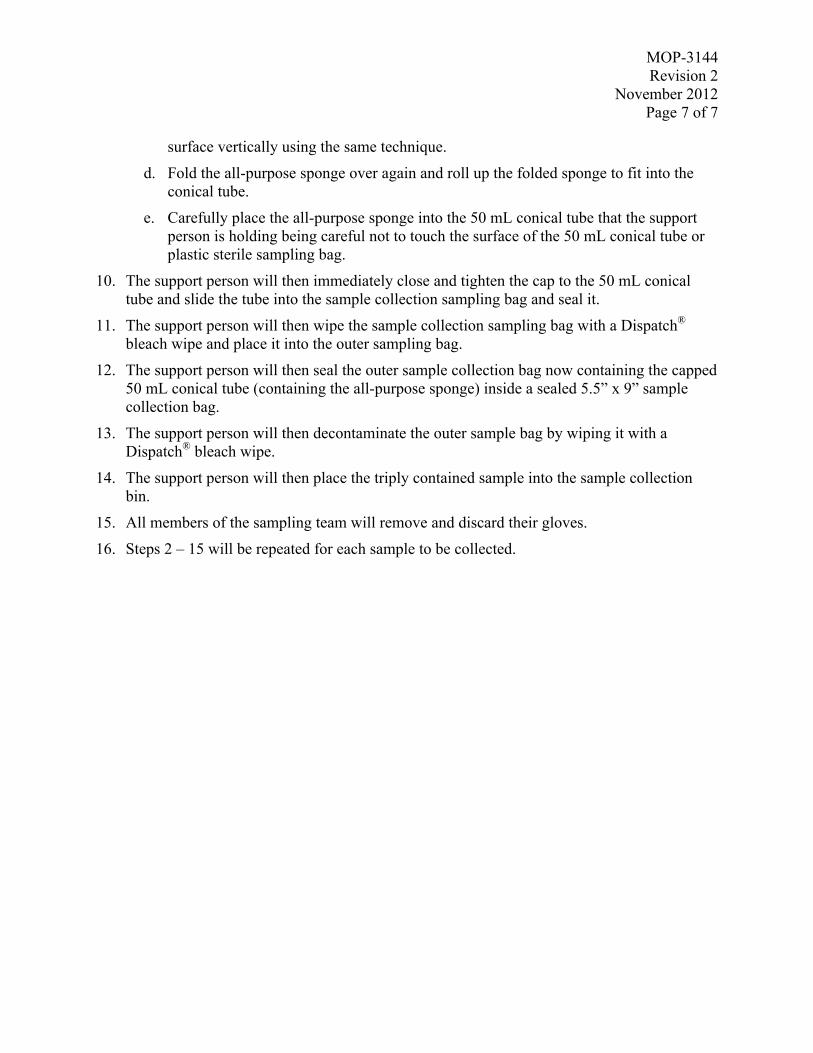
MOP-3144Revision 2
November 2012Page 7 of 7
surface vertically using the same technique.
d. Fold the all-purpose sponge over again and roll up the folded sponge to fit into theconical tube.
e. Carefully place the all-purpose sponge into the 50 mL conical tube that the supportperson is holding being careful not to touch the surface of the 50 mL conical tube orplastic sterile sampling bag.
10. The support person will then immediately close and tighten the cap to the 50 mL conicaltube and slide the tube into the sample collection sampling bag and seal it.
11. The support person will then wipe the sample collection sampling bag with a Dispatch®
bleach wipe and place it into the outer sampling bag.
12. The support person will then seal the outer sample collection bag now containing the capped50 mL conical tube (containing the all-purpose sponge) inside a sealed 5.5” x 9” samplecollection bag.
13. The support person will then decontaminate the outer sample bag by wiping it with aDispatch® bleach wipe.
14. The support person will then place the triply contained sample into the sample collectionbin.
15. All members of the sampling team will remove and discard their gloves.
16. Steps 2 – 15 will be repeated for each sample to be collected.

MOP-3145 Revision 5
November 2012 Page 1 of 6
Miscellaneous Operating Procedure (MOP) 3145: Procedure for Vacuum Sock Sampling of Large and Small Coupons
Prepared by: __________________________________________ Date: 11/15/2012 Stella McDonald, ARCADIS Work Assignment Leader
Reviewed by: __________________________________________ Date: 11/15/2012 Dahman Touati, ARCADIS Project Manager
Approved by: __________________________________________ Date: 11/15/2012
Worth Calfee, EPA Work Assignment Manager
Prepared for
National Homeland Security Research Center Office of Research and Development
U.S. Environmental Protection Agency Research Triangle Park, NC 27711
Prepared by
ARCADIS U.S., Inc.
4915 Prospectus Drive, Suite F Durham, NC 27713

MOP-3145 Revision 5
November 2012 Page 2 of 6
MOP-3145 TITLE: PROCEDURE FOR VACUUM SOCK SAMPLING OF LARGE AND SMALL
COUPONS SCOPE: This MOP describes the procedure for vacuum sampling of porous areas. PURPOSE: The purpose of this MOP is to ensure consistent and representative sampling of
such areas. EQUIPMENT (quantities are per sampling kit)
• 1 – Gamma irradiated vacuum sock filtration kit
• 2 - Fisherbrand bags with round wire enclosure, 5.5” x 15” (Fisher Scientific, p/n 14-955-181)
• 1 - Fisherbrand bag with round wire enclosure, 10” x 14” (Fisher Scientific, p/n 01-002-53)
• 1 – 7.5” “cable-tie” (McMaster Car, Item# 7130K59)
• Dispatch wipes
• Fisher Scientific CLEAN_WIPES (Catalog No. 06-664-14) prepared with 400 mL of 3% Sodium Thiosulfate solution (90mL of 1N STS in 310mL DI water)
• Fisher Scientific CLEAN_WIPES (Catalog No. 06-664-24) premoistened with 70% isopropyl alcohol
• Permanent marker
• Nitrile gloves
• OMEGA HEPA vacuum
1.0 PREPARATION All materials needed for each sample to be collected will be prepared in advance. A sample kit for a single vacuum sock sample will be prepared using the procedure in MOP-3141A, Procedure for Assembling Irradiated Vacuum Sock Sampling Kits.
2.0 VACUUM SAMPLING OF SMALL (14” by 14”) COUPONS

MOP-3145 Revision 5
November 2012 Page 3 of 6
The following procedure will be used in this study for vacuum sock sampling of each coupon surface: 1. A two person team will be used, employing aseptic technique. The team will consist of a
sampler and a support person.
2. Both members of the sampling team will each don a pair of sampling gloves (a new pair per sample); the sampler’s gloves shall be sterile sampling gloves if he/she is placing a template onto the sample. Both members shall wear dust masks to further minimize potential contamination of the samples. Further respiratory protection beyond a dust mask may be required to protect the sampling team (e.g., SAR; this will be specified in the project QAPP).
3. The sampler will plug in the vacuum power cord and then don his/her sterile gloves.
4. The vacuum will be powered through a foot switch to allow the sampler to turn the vacuum on and off. In general, care should be taken to direct the vacuum exhaust away from samples.
5. The support person will aseptically unwrap a template (if used) from the bag and present it to the sampler, taking care to not touch the template.
6. The sampler will place the template onto the coupon surface.
7. The sampler will wipe the hose connection end (that receives the vacuum sock) first with a fresh dispatch wipe, followed with a fresh CLEAN-WIPE containing 3% STS, followed by a fresh CLEAN-WIPE containing the 70% isopropyl alcohol.
8. The sampler will hold the vacuum nozzle for the support person to place the vacuum sock assembly onto the nozzle.
9. The support person will open the sampling supply bin and remove the vacuum sock sample kit from the bin.
10. The support person will record the sample collection bag ID number on the sampling log sheet or in the laboratory notebook.
11. The sampler and support person will ensure that the correct sample coupon has been selected, referencing the coupon code on the sampling bag.
12. The support person will record the coupon code on the sampling log sheet next to the corresponding vacuum sock collection bag number that was just recorded.
13. The support person will:
a. Open the vacuum sock sample kit outer bag and remove the unlabelled vacuum sock assembly bag.
b. Tear open the bag containing the vacuum sock assembly and, working from the outside of the bag, maneuver the assembly from the bottom to expose the cardboard applicator tube opening.
c. Firmly place the vacuum sock assembly onto the nozzle of the vacuum tube, using the bag to handle the vacuum sock assembly, while the sampler holds the vacuum nozzle.

MOP-3145 Revision 5
November 2012 Page 4 of 6
14. The sampler will:
a. Ensure that the sock is correctly placed on the nozzle and adjust, if necessary. Care must be taken to not puncture or tear the sock.
b. Turn on the vacuum.
c. Vacuum “horizontally” using S-strokes to cover the entire area of the material surface not covered by the template, while keeping the vacuum nozzle angled so that the tapered opening of the vacuum sock is flush with the sample surface.
d. Vacuum the same area “vertically” using the same technique.
e. Turn off the vacuum when sampling is completed.
15. The sampler will remove the vacuum sock assembly from the nozzle, taking care to only touch the cardboard and blue sections of the sock.
a. Remove the sock assembly from the vacuum hose. Take care not to touch the sock inside the tube (Figure 1a shows the sock assembly).
b. Loosen the nozzle by pulling it free of the longer tube, while holding onto the blue sock filter, and lightly replacing it in the longer tube.
c. Unfold the blue portion of the sock filter so that it is folded over the nozzle tubing (Figure 1b).
d. While holding both section of cardboard tubing (one in each hand), partially remove the angled section of tubing.
e. Present the sock to the support person, who will cinch the sock closed using a plastic “cable tie” at the blue portion between the cardboard tubes (Figures 1c and 1d).
f. Reconnect the two cardboard tubes (Figure 1e).
g. Place nozzle end up in a labeled 5.5” x 15” bag held by the support person.
a. b.

MOP-3145 Revision 5
November 2012 Page 5 of 6
c. d.
e.
Figure 1. (a) Vacuum sock assembly, (b) blue portion of sock over nozzle tubing, (c,d) cinching the sock with the “cable tie”, and (e) the two cardboard tubes reconnected.
16. The support person will then seal the outer sterile sampling bag and wipe it with a Dispatch® wipe.
17. The support person will then place this into the labeled 10” x 14” sample bag now containing the outer and inner bags, the inner containing the vacuum sock assembly. The outermost bag will then be wiped with a Dispatch® wipe.
18. The sampler will wipe down the nozzle (inside and out) and end of the tubing first with a Dispatch® wipe, next with a wipe pre-moistened with 3% STS, next with a wipe pre-moistened with 70 % ethanol.
19. The support person will then place the triply contained sample into the sample collection bin.

MOP-3145 Revision 5
November 2012 Page 6 of 6
20. All members of the sampling team will remove and discard their gloves.
21. Steps 2 – 20 will be repeated for each sample to be collected.

MOP-3161-F
Revision 1
April 2013
Page 1 of 7
Miscellaneous Operating Procedure (MOP) 3161-F:
Aerosol Deposition of Spores on HVAC Filter Under Flow
Prepared by: _________________________________________ Date: 4/29/2013
Matt Clayton, ARCADIS Work Assignment Leader
Reviewed by: _________________________________________ Date: 4/29/2013
Dahman Touati, ARCADIS Project Manager
Approved by: __________________________________________ Date: 4/29/2013
Worth Calfee, EPA Work Assignment Manager
Prepared for
National Homeland Security Research Center Office of Research and Development
U.S. Environmental Protection Agency Research Triangle Park, NC 27711
Prepared by
ARCADIS U.S., Inc.
4915 Prospectus Drive, Suite F
Durham, NC 27713

MOP-3161-F
Revision 1
April 2013
Page 2 of 7
MOP 3161-F
TITLE: AEROSOL DEPOSITION OF SPORES ON HVAC FILTER UNDER
FLOW
SCOPE: This MOP outlines the procedure for the deposition of a spore loaded aerosol onto
an HVAC filter under high flow conditions.
PURPOSE: To provide a procedure for the consistent deposition of spores onto HVAC filters
under flow.
MATERIALS
One 14” x 14” Aerosol Deposition Apparatus (ADA) (per inoculation)
One 14” x 14” gasket (per inoculation)
ADAdapter (see Figure 2)
Dispatch® wipes
STS Wipes
Isopropyl Alcohol Wipes
High Volume Sampler (Thermo Andersen 100042-00)
MOP 3161 ( and associated materials)
MOP 3168
Sterile forceps – Posi-Grip® Ref # 7190
Quartz filter sampling kits (prepared by BioLab)
Sterile filter sampling bag (VHP bag sterilized with EtO)
Enclosure aeration duct
Fisherbrand ® labeling tape – Catalog # - 15-951
Foot power switch – McMaster Item #96618
Sterilized Quartz filter (1 per inoculation) - WHATMAN® G653 Cat#-18209932
Sterilized 14” x 14” HVAC filter (1 per inoculation) - Purafilter 2000®
Medium binder clips – Staples ® Model#-10668-CC
Large binder clips - Staples ® Model#-10669
Blue spring clamps – Workforce 573-682
12” Double-sided sticky tape – Polyken 105C Carpet Tape

MOP-3161-F
Revision 1
April 2013
Page 3 of 7
1.0 PREPARATION AND ASSEMBLY
1. Sterilize one 14” x 14” ADA, one 14” x 14” gasket, and an ADAdapter at least 3 days prior
to allow for off-gassing.
2. Sterilize one VHP bag per coupon using ethylene oxide (EtO) at least 3 days prior to
testing.
3. Set up the High Volume Sampler in the enclosure vented to the enclosure aeration system.
NOTE: Refer to Figure 1 to ensure assembly is correct during Steps 3-8. Figure 2 shows
the completed blower and ADA assembly.
4. The filter base on the blower assembly must be lifted above the top face of the sampler using
angle iron (See Figure 1a) to allow the seal between the base and ADAdapter to be clamped.
5. A two-person team is employed to aseptically install the quartz filter on top of the blower
assembly base as in MOP 3168, except there is no need for a third person to hold the bracket
as it is not required with this assembly (see Figure 1b).
6. Install the ADAdapter on top of the filter ensuring contact with the gasket. It is important that
the filter is installed such that all edges are covered by the gasket on the bottom of the
ADAdapter to ensure all airflow passes through it. Clamp the ADAdapter to the assembly
using small binder clips (see Figure 1c).
7. Once the ADAdapter is securely in place, aseptically install the 14” x14” HVAC filter.
Remove the filter from the bag using sterile gloves and place on top of the ADAdapter.
Ensure the filter is installed in the orientation pictured in Figure 1d.
8. Finally, Install the 14” x 14” gasket and ADA on top of the filter and secure the seal with the
spring clamps. Ensure the ADA is equipped with 4 filters and the top port is sealed with the
included mechanism (see Figure 1e).
9. Before proceeding to Section 2.0, prepare adequate space for the number of filters to be
puffed on cleaned tables. Use double-sided tape to create 16” x 16” settling areas, one for
each puffed filter. It is necessary to clean the table surfaces with Dispatch wipes, water and
alcohol. Do not use paper coverings due to using double-sided tape.

MOP-3161-F
Revision 1
April 2013
Page 4 of 7
a. b.
c. d.
e.
Figure 1. (a) Blower assembly base, (b) Quartz filter installed, (c) ADAdapter installed and clamped,
(d) HVAC filter installed, and (e) Completed assembly.

MOP-3161-F
Revision 1
April 2013
Page 5 of 7
Figure 2. Blower and ADA assembly
ADAdapter
14x14 ADA
Blower Assembly
base

MOP-3161-F
Revision 1
April 2013
Page 6 of 7
2.0 PUFFING PROCEDURE
1. Determine the weight of the MDI canister using a balance. Record the MDI ID number and
the weight (to the nearest 0.01g) in lab notebook. In addition, keep a record of the total
number of ‘puffs’ dispensed for each MDI canister.
NOTE: The MDI canister full is approximately 15 grams, an empty canister is approx 9.5
grams. To ensure the canister contains adequate spore suspension for dosing,
canisters should be retired from use when their weight falls below 10.5 grams.
2. Next, assemble the MDI and actuator by inserting the MDI into the actuator, taking care not to
activate the MDI.
3. Vortex the MDI/actuator assembly for 30 seconds (the MDI canister should be in direct contact
with the vortex mixer).
4. Holding the MDI/actuator assembly upright, in a swift, firm motion, dispense three test ‘puffs’
into the aerosol trap to prime the MDI. It is important to vortex the assembly 10 seconds
before every puff (except 30 seconds prior to the initial puff of the experiment).
5. Vortex the assembly 10 seconds, and attach it to the ADA lid by mating the ADA adaptor to
the hole in the ADA lid. Loosen the lid screws enough to allow the lid to be slid into the
‘open’ position. Secure the lid in the open position by tightening the lid screws.
NOTE: The ‘open’ position is achieved when the hole in the lid aligns with the hole in the top
of the ADA.
6. Using the foot switch, start the blower and allow the unit to flow for 15 seconds.
7. At 15 seconds, dispense the spores by activating the MDI with a swift, firm motion. Hold the
MDI in the activated position for 3 seconds before releasing. Activation is best achieved by
grasping the MDI/actuator with two hands, and using a thumb to press the bottom of the MDI
canister.
8. After 30 seconds total, follow the reverse order of the lid opening procedure to close the ADA
lid, and turn off the blower using the foot switch.
9. Determine the weight of the actuator-MDI using a balance, and record the weight in lab
notebook.
NOTE: If the dosing puff is faulty, return to Step 5 and attempt a second puff on the current
filter. Do not proceed to the next filter until a ‘successful’ puff has been delivered. A
‘successful’ puff is achieved when the weight of the actuator- MDI assembly has a

MOP-3161-F
Revision 1
April 2013
Page 7 of 7
0.04gram-0.07gram loss. Familiarity and professional judgment will be needed to
determine the success of a puff.
10. Once the filter is successfully puffed, remove the ADA , gasket, and filter assembly. Clamp the
filter to the assembly using large binder clips, and place on the double sided tape.
11. Remove the ADAdapter and place on a clean surface.
12. Aseptically recover the quartz filter as in MOP 3168.
13. Clean the ADAdapter with Dispatch® wipes, STS wipes, and isopropyl alcohol wipes before
proceeding to Step 14.
14. For each additional filter, proceed to apparatus assembly, using a new sterile ADA and gasket
for each inoculation (Step 5, Section 1).
15. Repeat Steps 1.5 to 2.14 until all filters have been puffed (see test plan for number of samples).
16. Once all coupons have been puffed, remove the MDI from the actuator and weigh. Record the
final weight and total number of puffs.
17. Allow spores to settle onto the coupon surface for at least 18 hours. Settling time should not
exceed 26 hours.
3.0 RECOVERY
1. After 18 hours settling time, carefully remove binder clips and remove ADA and gasket from
coupon surface, taking care not to disturb the surface of the coupon.
2. Don sterile gloves and transfer the filter to sterilized VHP bag. Carefully tape the bag closed,
ensuring an air tight seal.
3. The VHP bag should be placed in tertiary containment before transport to the APPCD
Biocontaminant Laboratory for analysis.

MOP 3161-HDRevision 3
November 2012Page 1 of 7
Miscellaneous Operating Procedure (MOP) 3161-HD:
Aerosol Deposition of Spores onto Material Coupon Surfaces usingthe Aerosol Deposition Apparatus (ADA) – High Dosing
Prepared by: __________________________________________ Date: 11/15/2012Stella McDonald, ARCADIS Work Assignment Leader
Reviewed by: __________________________________________ Date: 11/15/2012Dahman Touati, ARCADIS Project Manager
Approved by: __________________________________________ Date: 11/15/2012Worth Calfee, EPA Work Assignment Manager
Prepared for
National Homeland Security Research CenterOffice of Research and Development
U.S. Environmental Protection AgencyResearch Triangle Park, NC 27711
Prepared by
ARCADIS U.S., Inc.4915 Prospectus Drive, Suite F
Durham, NC 27713

MOP 3161-HDRevision 3
November 2012Page 2 of 7
MOP 3161-HD
TITLE: AEROSOL DEPOSITION OF SPORES ONTO MATERIAL COUPONSURFACES USING THE AEROSOL DEPOSITION APPARATUS (ADA) –HIGH DOSING
SCOPE: This MOP outlines the procedure for assembly and usage of the AerosolDeposition Apparatus (ADA).
PURPOSE: Precise and highly repeatable aerosol deposition of bacterial spores onto materialsurfaces for detection, sampling, and/or decontamination studies.
Materials:
Aerosol Deposition Apparatus (ADA) (shown in Figure 1)
Metered Dose Inhaler (MDI) preloaded with a bacterial spore suspension of knownconcentration (i.e., 1 x 10⁹ spores per puff)
Vertical MDI Actuator (shown in Figure 2)
Material coupon (with dimensions at least that of the ADA)
ADA-coupon gasket (1 per ADA) (see Figure 1)
Clamping devices (i.e., medium-size steel binder clips, C-clamps (8 per ADA))
Vortex mixer (shown in Figure 4)
Aerosol trap (described in Appendix A and shown in Figure 4)
Personal Protective Equipment (PPE) (gloves, lab coat, safety goggles)
pH-adjusted bleach (pAB) (MOP 3128-A)
0.22µm pore-size syringe filters (shown in Figure 1)
PVC tubing (3/8” OD, 1/4” ID)
Mass balance (with 0.01 gram accuracy)
Bench liner
1.0 STERILIZATION OF MATERIALS
Prior to the start of any experiment, all components must be sterilized and stored in a sterileenvironment until usage. Sterilization is not necessary for binder clips, MDI, vortex, or theaerosol trap.

MOP 3161-HDRevision 3
November 2012Page 3 of 7
ADAs can be sterilized by autoclave, VHP, or by wiping with pH-adjusted bleach (pAB) withsubsequent deionized (DI) water and ethanol rinse/wipes. The ADA lid should be attached andin the closed position during the sterilization.
Figure 1. ADA apparatus
The MDI actuator, with attached MDI adaptor, can be wiped with pAB then rinsed with DIwater.
Figure 2. MDI and vertical actuator
ADA
ADA with lid inclosed position
Gasket
2.2umsyringe filter
MDI
VerticalActuator

MOP 3161-HDRevision 3
November 2012Page 4 of 7
Sterilization requirements for coupons vary by material. Regardless of the sterilization method,quality control (QC) checks (typically by collecting a swab sample per MOP 3135) should beadministered to ensure the effectiveness of the sterilization method.
Gasket sterilization may also vary by material. Care should be taken to thoroughly degas gasketsif sterilized via fumigation.
2.0 PROCEDURE
1. Begin by donning PPE (gloves, lab coat, and protective eyewear).
2. Clean the workspace by wiping with pAB, next with DI water , and lastly with a 70-90%solution of denatured ethanol. Alternatively, new, clean bench liner may be placed on thework surfaces. Make sure the workspace is clean and free of debris.
3. Discard gloves and replace with fresh pair.
4. Using aseptic techniques (when possible) assemble the coupon/ADA by first placing thesterilized material coupon onto the clean lab bench or workspace, next place the sterilizedgasket on top of the coupon, and lastly seat the ADA on the coupon + gasket. Orient eachcomponent so that it fits squarely with the previously placed item. Take care not to touch theinside of the ADA or the coupon surface. Secure these components by attaching medium-size binder clips, one at each corner, and one at the midpoint of each of the four sides of theADA. The binders should firmly secure the coupon to the ADA, and apply sufficientpressure to the gasket to seal the union. If material coupons are too large to use binder clipsother methods may be used to secure the coupon and gasket to the ADA (i.e., larger clamps,weight added to the ADA, etc.). Lastly, attach 0.2 um syringe filters to each vent tube on allADAs (4 per ADA). Syringe filters can be attached using PVC tubing (3/8” OD, 1/4” ID).
5. Determine the weight of the MDI canister using a balance. Record the MDI ID number andthe weight (to the nearest 0.01g) in lab notebook. In addition, keep a record of the totalnumber of ‘puffs’ dispensed for each MDI canister.
NOTE: The MDI canister full is approximately 15 g, an empty canister is approx 9.5 g. Toensure the canister contains adequate spore suspension for dosing, canisters shouldbe retired from use when their weight falls below 10.5 g.
6. Next, assemble the MDI and actuator by inserting the MDI into the actuator, taking care notto activate the MDI.
7. Vortex the MDI/actuator assembly for 30 seconds (the MDI canister should be in directcontact with the vortex mixer).
8. Holding the MDI/actuator assembly upright (Figure 3), with a swift, firm motion, dispensethree test ‘puffs’ into the aerosol trap to prime the MDI. It is important to vortex the

MOP 3161-HDRevision 3
November 2012Page 5 of 7
assembly 10 seconds before every puff (the exception being 30 seconds prior to the initialpuff of the experiment, as prescribed in Step 7).
Figure 3. MDI orientation while dispensing test puffs into the aerosol trap.
9. Vortex the assembly for 10 seconds and then attach to the ADA lid by mating the ADAadaptor to the hole in the ADA lid. Loosen the lid screws enough to allow the lid to be slidinto the ‘open’ position. Secure the lid in the open position by tightening the lid screws.
NOTE: The ‘open’ position is achieved when the hole in the lid aligns with the hole in thetop of the ADA.
10. With a swift, firm motion, dispense the spores by activating the MDI. Hold the MDI in theactivated position for 3 seconds before releasing. Activation is best achieved by grasping theMDI/actuator with two hands, and using a thumb to press the bottom of the MDI canister.
11. Follow the reverse order of the lid opening procedure to close the ADA lid.
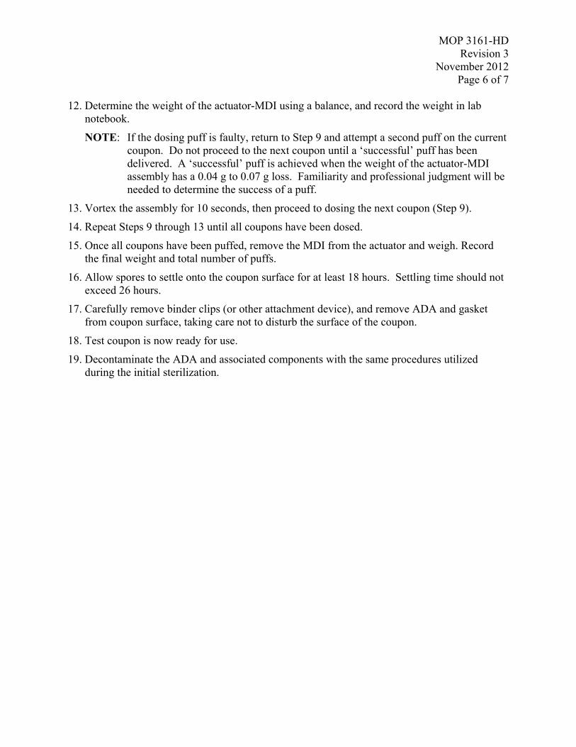
MOP 3161-HDRevision 3
November 2012Page 6 of 7
12. Determine the weight of the actuator-MDI using a balance, and record the weight in labnotebook.
NOTE: If the dosing puff is faulty, return to Step 9 and attempt a second puff on the currentcoupon. Do not proceed to the next coupon until a ‘successful’ puff has beendelivered. A ‘successful’ puff is achieved when the weight of the actuator-MDIassembly has a 0.04 g to 0.07 g loss. Familiarity and professional judgment will beneeded to determine the success of a puff.
13. Vortex the assembly for 10 seconds, then proceed to dosing the next coupon (Step 9).
14. Repeat Steps 9 through 13 until all coupons have been dosed.
15. Once all coupons have been puffed, remove the MDI from the actuator and weigh. Recordthe final weight and total number of puffs.
16. Allow spores to settle onto the coupon surface for at least 18 hours. Settling time should notexceed 26 hours.
17. Carefully remove binder clips (or other attachment device), and remove ADA and gasketfrom coupon surface, taking care not to disturb the surface of the coupon.
18. Test coupon is now ready for use.
19. Decontaminate the ADA and associated components with the same procedures utilizedduring the initial sterilization.

MOP 3161-HDRevision 3
November 2012Page 7 of 7
APPENDIX A - Aerosol Trap
Purpose: This device allows test puffs of the MDI to be deployed without contamination of thesurrounding area. Spores are pulled into the trap, contained, and inactivated.
This device consists of a suction source, a trap (containing pAB), and an inlet funnel.Aerosolized spores are pulled into the funnel, and forced into the trap. The spores are collectedand inactivated as the aerosol flows through the pAB solution. The effluent air traveling towardthe suction device is spore-free downstream of the trap. See Figure 4.
The aerosol trap should be assembled inside a biological safety cabinet (BSC) or chemical fumehood.
Figure 4. Aerosol trap
Aerosol trap
Vortexer

MOP-3161-LD
Revision 1
April 2013
Page 1 of 7
Miscellaneous Operating Procedure (MOP) 3161-LD:
Aerosol Deposition of Spores onto Material Coupon Surfaces using
the Aerosol Deposition Apparatus (ADA) – Low Dosing
Prepared by: _________________________________________ Date: 4/29/2013
Matt Clayton, ARCADIS Work Assignment Leader
Reviewed by: _________________________________________ Date: 4/29/2013
Dahman Touati, ARCADIS Project Manager
Approved by: __________________________________________ Date: 4/29/2013
Worth Calfee, EPA Work Assignment Manager
Prepared for
National Homeland Security Research Center
Office of Research and Development
U.S. Environmental Protection Agency
Research Triangle Park, NC 27711
Prepared by
ARCADIS U.S., Inc.
4915 Prospectus Drive, Suite F
Durham, NC 27713

MOP-3161-LD
Revision 1
April 2013
Page 2 of 7
MOP 3161-LD
TITLE: AEROSOL DEPOSITION OF SPORES ONTO MATERIAL COUPON
SURFACES USING THE AEROSOL DEPOSITION APPARATUS (ADA) –
LOW DOSING
SCOPE: This MOP outlines the procedure for assembly and usage of the Aerosol
Deposition Apparatus (ADA) for low dosing.
PURPOSE: To provide a procedure for repeatable aerosol deposition of bacterial spores onto
material surfaces for detection, sampling, and/or decontamination studies.
MATERIALS
Aerosol Deposition Apparatus (ADA)
Metered Dose Inhaler (MDI) preloaded with a bacterial spore suspension of known
concentration (i.e., 5 x 10⁶ spores per puff or less, also designated as 5E6)
MDI Actuator with ADA adaptor (adaptor required for proper attachment of actuator to
ADA lid). The MDI actuator label must match the concentration and organism of the
MDI.
Material coupon (with dimensions at least that of the ADA)
ADA-coupon gasket (1 per ADA)
Clamping devices (i.e., medium-size steel binder clips, C-clamps (8 per ADA))
Vortex mixer
Aerosol trap (described in Appendix A)
PPE (gloves, lab coat, P95 dust mask, cap or hair bonnet, safety goggles)
pH-adjusted bleach (pAB; prepared per MOP 3128)
0.22µm pore-size syringe filters
PVC tubing (3/8” OD, 1/4” ID)
mass balance (with 1 mg accuracy)
canned air duster

MOP-3161-LD
Revision 1
April 2013
Page 3 of 7
1.0 DISINFECTION OF MATERIALS
Prior to the start of any experiments, all components must be disinfected, and stored in as close
to a sterile environment as possible until usage. (Disinfection is not necessary for binder clips,
MDI, vortex, and the aerosol trap).
ADAs can be disinfected by autoclave, VHP, or pAB wiping with subsequent deionized water
(diH2O) and ethanol rinse/wipes. The ADA lid should be attached and in the closed position
during the disinfection.
MDI actuator with attached MDI adaptor can be wiped with pAB then rinsed with diH2O.
NOTE: DO NOT expose to ethanol, as ethanol will shatter the ADA adaptor.
Disinfection requirements for coupons vary by material. Regardless of disinfection method, QC
checks should be administered to ensure the effectiveness of the disinfection method.
Gasket disinfection may also vary by material.
2.0 PROCEDURE
1. Begin by donning PPE (gloves, lab coat, and protective eyewear).
2. Cover the tables with fresh bench liner.
3. Discard gloves and replace with fresh pair.
4. Using aseptic techniques (when possible) assemble the coupon/ADA by first placing the
disinfected material coupon onto the clean lab bench or workspace. Next place the
disinfected gasket on top of the coupon, and then seat the ADA on the coupon + gasket.
Orient each component so that it fits squarely with the previously placed item. Take care not
to touch the inside of the ADA or the coupon surface. Secure these components by attaching
medium-size binder clips, one at each corner, and one at the midpoint of each of the four
sides of the ADA. The binders should firmly secure the coupon to the ADA and apply
sufficient pressure to the gasket to seal the union. If material coupons are too large to use
binder clips, other methods may be used to secure the coupon and gasket to the ADA (i.e.,
larger clamps, weight added to the ADA, etc.).
Lastly, attach 0.2 um syringe filters to each vent tube on all ADAs (4 per ADA). Syringe
filters can be attached using PVC tubing (3/8” OD, 1/4” ID).
5. Determine the weight of the MDI canister using a balance. Record the weight (to the nearest
mg) in lab notebook. In addition, keep a record of the total number of ‘puffs’ dispensed for
each MDI canister.
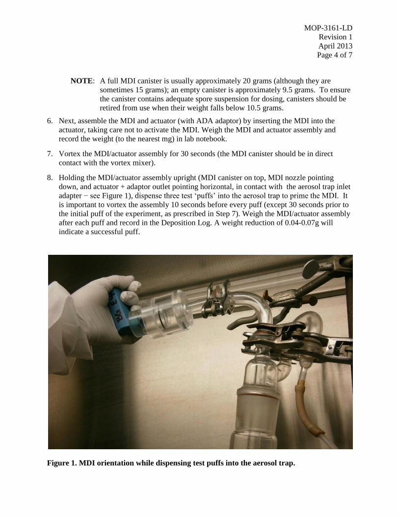
MOP-3161-LD
Revision 1
April 2013
Page 4 of 7
NOTE: A full MDI canister is usually approximately 20 grams (although they are
sometimes 15 grams); an empty canister is approximately 9.5 grams. To ensure
the canister contains adequate spore suspension for dosing, canisters should be
retired from use when their weight falls below 10.5 grams.
6. Next, assemble the MDI and actuator (with ADA adaptor) by inserting the MDI into the
actuator, taking care not to activate the MDI. Weigh the MDI and actuator assembly and
record the weight (to the nearest mg) in lab notebook.
7. Vortex the MDI/actuator assembly for 30 seconds (the MDI canister should be in direct
contact with the vortex mixer).
8. Holding the MDI/actuator assembly upright (MDI canister on top, MDI nozzle pointing
down, and actuator + adaptor outlet pointing horizontal, in contact with the aerosol trap inlet
adapter − see Figure 1), dispense three test ‘puffs’ into the aerosol trap to prime the MDI. It
is important to vortex the assembly 10 seconds before every puff (except 30 seconds prior to
the initial puff of the experiment, as prescribed in Step 7). Weigh the MDI/actuator assembly
after each puff and record in the Deposition Log. A weight reduction of 0.04-0.07g will
indicate a successful puff.
Figure 1. MDI orientation while dispensing test puffs into the aerosol trap.

MOP-3161-LD
Revision 1
April 2013
Page 5 of 7
9. Vortex the assembly 10 seconds, and attach it to the ADA lid by mating the ADA adaptor to
the hole in the ADA lid. Loosen the lid screws enough to allow the lid to be slid into the
‘open’ position. (The ‘open’ position is achieved when the hole in the lid aligns with the hole
in the top of the ADA.) Secure the lid in the open position by tightening the lid screws.
10. With a swift firm motion, dispense the spores by activating the MDI. Hold the MDI in the
activated position for 3 seconds before releasing. Activation is best achieved by grasping the
MDI/actuator with two hands, and using a thumb to press the bottom of the MDI canister.
Weigh the MDI and record in the Deposition Log assembly.
NOTE: If the dosing puff is faulty, return to Step 8 and attempt a second puff on the
current coupon. Do not proceed to the next coupon until a ‘successful’ puff has
been delivered. A ‘successful’ puff is achieved when the plume can be seen
through the clear ADA adaptor immediately following the puff. The puff results
in audible characteristics typical of a successful puff, and the proper weight
reduction is achieved. Familiarity and professional judgment will be needed to
determine the success of a puff.
11. Follow the reverse order of the lid opening procedure to close the ADA lid. Detach the
MDI/actuator assembly from the lid.
12. Remove the MDI from the actuator and determine the weight of the MDI using a balance,
record the weight in lab notebook.
13. Place the empty actuator into the aerosol trap and remove dosing residue from the inner
surface of the actuator using the canned air duster. Take care to blow the compressed air into
the bottom of the actuator so that the residue is blown directly into the aerosol trap.
14. Vortex the assembly for 10 seconds, holding the assembly upright (MDI canister on top,
MDI nozzle pointing down, and actuator + adaptor outlet pointing horizontal, towards the
aerosol trap inlet − see Figure 1), dispense a test puff into the aerosol trap (expect a faulty
puff, as the MDI requires recharging after a puff in the non-upright orientation). Repeat once
more (vortex 10 seconds, puff). Expect the subsequent puff to be characteristic (visually,
audibly, and with expected weight loss) of a successful puff. If the second test puff is
successful, proceed to dosing the next coupon (Step 9). If the second puff is faulty, repeat
Step 13.
15. Repeat Steps 9 through 13 until all coupons have been dosed.
16. Allow spores to settle onto the coupon surface for at least 18 hours. Settling time should not
exceed 26 hours.
17. Wearing the proper PPE, carefully remove binder clips (or other attachment device), and
remove ADA and gasket from coupon surface, taking care not to disturb the surface of the
coupon.

MOP-3161-LD
Revision 1
April 2013
Page 6 of 7
18. Test coupon is now ready for use.
19. Decontaminate the ADA and associated components with the same procedures utilized
during the initial disinfection.

MOP-3161-LD
Revision 1
April 2013
Page 7 of 7
APPENDIX A – AEROSOL TRAP
Purpose: This device allows test puffs of the MDI to be deployed without contamination of the
surrounding area. Spores are pulled into the trap, contained, and inactivated.
This device consists of a suction source, a trap (containing pAB), and an inlet funnel.
Aerosolized spores are pulled into the funnel and forced into the trap. The spores are collected
and inactivated as the aerosol flows through the pAB solution. The effluent air traveling toward
the suction device is spore-free downstream of the trap. See Figure 2.
The aerosol trap should be assembled inside a biological safety cabinet (BSC) or chemical fume
hood.
Figure 2. Schematic drawing of Aerosol Trap.
Suction
Device
Suction
Device
Suction
Device
pH-adjusted bleach

MOP-3164
Revision 2
April 2013
Page 1 of 11
Miscellaneous Operating Procedure (MOP) 3164:
Procedure for 37MM Cassette and Trace Evidence Filter Vacuum
Sampling of Large and Small Coupons
Prepared by: _________________________________________ Date: 4/29/2013
Matt Clayton, ARCADIS Work Assignment Leader
Reviewed by: _________________________________________ Date: 4/29/2013
Dahman Touati, ARCADIS Project Manager
Approved by: __________________________________________ Date: 4/29/2013
Worth Calfee, EPA Work Assignment Manager
Prepared for
National Homeland Security Research Center
Office of Research and Development
U.S. Environmental Protection Agency
Research Triangle Park, NC 27711
Prepared by
ARCADIS U.S., Inc.
4915 Prospectus Drive, Suite F
Durham, NC 27713

MOP-3164 Revision 1 April 2012
Page 2 of 11
TITLE: PROCEDURE FOR 37MM CASSETTE AND TRACE EVIDENCE FILTER VACUUM SAMPLING OF LARGE AND SMALL COUPONS
SCOPE: This MOP describes the procedure for vacuum sampling of porous areas. PURPOSE: The purpose of this MOP is to ensure consistent and representative sampling of
such areas.
A: 37 mm filter EQUIPMENT (starred* quantities are per sampling kit)
• *1 – 37 mm Filter cassette loaded with desired filter - 0.3 µm pore size PTFE membrane (SKC 225-1723)
- 0.8 µm pore size MCE membrane (SKC 225-3-01)
• Vac-U-Go pump (SKC 228-9605)
• Rotameter (SKC 320-100)
• Tygon tubing, 1/4 in ID, 7/16 in OD, 50ft (SKC 225-1345)
• *Two PVC adapters, 250/pkg (SKC 225-132A)
• *One BD Falcon Sterile 15 mL Polyprolene Conical Tubes (fishersci.com, P/N 225-352196)
• *Two 5.5” x 9” 3.5 mil sterile sampling bags with flat-wire closures (fishersci.com, Item# 14-955-187)
• *10” x 14” overpack sample bag with round wire enclosure (fishersci.com, Item# 01-002-53)
• 12” x 12” Template
• Permanent marker
• Nitrile gloves
• Timer
1.0 PREPARATION All materials needed for each sample to be collected will be prepared in advance. A sample kit for a single cassette vacuum sample will be prepared using the following procedure.
1) Don nitrile gloves.
2) In laboratory, assemble nozzles:

MOP-3164
Revision 2
April 2013
Page 3 of 11
a) Cut the sampling nozzle from tygon tubing as follows: Using scissors, cut a section of
tygon tubing 1-inch long, then cut one end of the tubing at approximately a 45-degree
angle.
b) Place the nozzle onto a PVC adapter.
c) Prepare 25% more nozzles than required by the testing protocol.
d) Sterilize the nozzles with a 15 minute gravity cycle of the autoclave.
3) In laboratory, assemble cassette kit:
a) Label the 37 mm cassette with a unique sample ID.
b) Label the 15 mL conical tube with the same unique sample ID.
c) Aseptically remove the cassette plugs and place a PVC adaptor onto each end of the
cassette. Save the removed plugs for step f) below.
d) Cut a 20 cm long piece of tubing with the scissors.
e) Place the 20 cm tubing onto the downstream end of the cassette..
f) Place the sampling nozzle (1-inch section of tubing) onto the upstream end of the
cassette with the angled side furthest from the cassette.
g) Place the cassette with PVC adaptors, 20 cm tubing, and nozzle into a 5.5” x 9” 3.5
mil bag, making sure the end of the cassette that attaches to the vacuum tubing is
closest to the bag opening. (see Figure 1)
h) Place the red plugs removed from the cassette in step a) above into the same 5.5” x 9”
bag.
i) Place the 15 mL conical tube and the 5.5” x 9” bag with 37mm cassette assembly and
plugs into the 10” x 14” overpack bag.
j) Place an additional sterile small bag into the overpack bag.
4) Label the 10” x 14” bag with the sample ID.
5) Store sample kits in a clean dry location.

MOP-3164
Revision 2
April 2013
Page 4 of 11
Figure 1. 37mm Cassette Vacuum Inner Bag
2.0 VACUUM SAMPLING OF SMALL (12” by 12”) COUPONS
The following procedure will be used in this study for 37mm vacuum sampling of each coupon
surface:
1. A two-person team will be used, employing aseptic technique. The team will consist of a
sampler and a support person. In times when a third person (sample handler) is present, he or
she will act as an assistant to the support person for data recording.
2. The sampler will plug in the Vac-U-Go pump power cord, and attach the calibrated
rotameter to the pump. Turn on the pump and adjust the pump valve until the flow rate is 20
± 2 LPM. Record the flow rate in the project notebook. The sampler will then don his/her
sterile gloves.
3. Both members of the sampling team will each don a pair of sampling gloves (a new pair per
sample); the sampler’s gloves shall be sterile sampling gloves as they are the only member of
the team in contact with the sample. Both members shall wear dust masks to further
minimize potential contamination of the samples. Further respiratory protection beyond a
dust mask may be required to protect the sampling team (e.g., SAR; this will be specified in
the project QAPP).
4. The Vac-U-Go pump will be maintained on a rolling cart for easy movement into place.
5. The support person will aseptically unwrap a template from the bag and present it to the
sampler, taking care to not touch the template.
6. The sampler will place the template onto the coupon surface.
7. The support person will open the sampling supply bin and remove the 37mm cassette sample
kit from the bin.

MOP-3164
Revision 2
April 2013
Page 5 of 11
8. The support person or assistant will record the sample collection bag ID number on the
sampling log sheet or in the laboratory notebook.
9. The sampler and support person will ensure that the correct sample coupon has been selected,
referencing the coupon code on the sampling bag.
10. The support person or assistant will record the coupon code on the sampling log sheet next to
the corresponding 37mm cassette collection bag number that was just recorded.
11. The support person will:
a. Open the 37mm cassette sample kit outer bag and remove the unlabeled 37 mm
cassette assembly bag.
b. Open the small unlabeled bag containing the 37 mm cassette assembly.
c. Hold the bag so that the sampler can remove the kit.
d. The support person will hold the tubing for the sampler to place the 37mm cassette
assembly onto the tubing.
12. The sample handler will remove the 37 mm cassette assembly from the bag and attach to the
tygon vacuum tube held by the support person.
13. The support person or assistant will be prepared to record the duration of sampling. Prompts
should be given to the sampler so that the sample duration is close to the values in the Table
1.
Table 1: Suggested Sample Duration and Speed for 12” x 12” surface area
Material Total Sampling
duration
Single Pass
duration
Number of passes
per direction
Concrete 300 seconds 3 seconds 50
Upholstery 300 seconds 3 seconds 50
Carpet 300 seconds 3 seconds 50
14. The sampler will:
a. Ensure that the filter is correctly placed on the tygon vacuum tube and adjust, if
necessary.
b. Turn on the vacuum.
c. Vacuum “horizontally” using S-strokes to cover the entire area of the material surface
not covered by the template, while keeping the tygon nozzle angled so that the
tapered opening of the tygon nozzle is flush with the sample surface.
Note: a target duration of time to vacuum each coupon should be determined prior to
testing for each material type. The sampler should pace the speed of the nozzle such
that the target sampling time is achieved for each coupon.

MOP-3164
Revision 2
April 2013
Page 6 of 11
d. Vacuum the same area “vertically” using the same technique.
e. Turn off the vacuum when sampling is completed.
f. Hold the nozzle and remove it from the cassette.
15. The support person will remove the 17 mm tube from the sample kit and open the tube.
16. The sampler will place the nozzle into the tube with the adapter end down while holding the
cassette in the opposite hand.
17. The support person will seal the tube and place in the small unlabeled bag.
18. The sampler will use the “nozzle” hand to remove the tubing from the outlet side of the
cassette and hold the cassette out to the support person.
19. The support person will
a. Don a fresh pair of gloves.
b. Seal the cassette with the two red plugs found in the small unlabeled sample
collection bag.
20. The support person will open the small unlabeled sample collection bag, and the sampler will
place the secured 37 mm cassette inside with the 15 mL conical tube.
21. The support person will then seal the small unlabeled sample collection bag and wipe it with
a Dispatch®
wipe.
22. The support person will open the labeled 10” x 14” overpack bag and place the smaller
unlabeled collection bag containing the cassette inside.
23. The support person will then seal the labeled 10” x 14”overpack bag and wipe it with a
Dispatch®
wipe.
24. The sampler will remove the used 20 cm length of tubing and discard.
25. The support person will then place the double contained sample into the sample collection bin.
26. All members of the sampling team will remove and discard their gloves.
27. Steps 3 – 22 will be repeated for each sample to be collected.
28. At the completion of testing, determine the final flow rate of the vacuum using the rotameter
and record in the project notebook.
B: 3M Trace Evidence Filter
Materials:
PPE (gloves, lab coat, safety goggles)

MOP-3164
Revision 2
April 2013
Page 7 of 11
Sterile, sealed 10”x15” Twirl-em bags
Alcohol wipes
Dry wipes moistened with 3% sodium thiosulfate
Sharpie and/or pre-printed labels
Secondary containment such as a large Tupperware bin
Lab notebook
QAPP for project that is utilizing the Trace Evidence Filter samples
3M Forensic Vacuum Filter (Trace Evidence Filter) (Precision Data Products, Grand Rapids,
MI catalog #FF-1), referred to as TEF
1.0 PROCEDURE
1.1 Assembly of Trace Evidence Filter Kits
TEF kits are assembled in the following manner:
1. TEF kits can be assembled outside of the biological safety cabinet, in a dry, clean area.
Make certain to use proper PPE, including gloves, while handling all TEF kit materials.
Gather all materials to assemble the kits before assembly. These materials include:
- 3M Forensic Vacuum Filters
- 10”x15” Twirl-em bags
- Sharpie or pre-printed labels
2. Obtain a copy of the labeling scheme for the samples. This may be detailed in the QAPP.
For each TEF kit, use a Sharpie and label a large 10” x 15” Twirl-em bag with the correct
sample ID. Using 2 pre-printed labels, label the bag containing the TEF with a permanent
label and a label that can be easily removed. The removable label will be placed on the TEF
after sampling.

MOP-3164
Revision 2
April 2013
Page 8 of 11
Figure 1: Example of a permanent and removable label on a TEF
3. Open the labeled, 10” x 15” Twirl-em bags one at a time. Place the labeled, TEF in the 10” x
15” Twirl-em bags that have the corresponding label. Add a non-labeled, 10” x 15” Twirl-
em bag in the labeled 10” x 15” Twirl-em bag containing the TEF. This completes the TEF
kit assembly. In the lab notebook, record the date and project for which the TEF kits were
assembled.
4. Place the assembled TEF kits into a secondary containment, such as a large Tupperware bin.
When moving the kits to a sampling location, always have them in secondary containment.
Figure 2: Example of an assembled TEF kit

MOP-3164
Revision 2
April 2013
Page 9 of 11
2.0 VACUUM SAMPLING OF SMALL (12” by 12”) COUPONS
The following procedure will be used in this study for TEF vacuum sampling of each coupon
surface:
A two-person team will be used, employing aseptic technique. The team will consist of a
sampler and a support person. In times when a third person (sample handler) is present, he or she
will act as an assistant to the support person for data recording.
1) The Omega vacuum will be maintained on a rolling cart for easy movement into place.
2) The sampler will plug in the Omega Vacuum into a variable transformer (Staco Energy
Products Co., Model 3PN1010B) set on 50%. The sampler will wipe down the nozzle
(inside and out) and end of the tubing first with a Dispatch® wipe, next with a wipe pre-
moistened with 3% Sodium thiosulphate, next with a wipe pre-moistened with 70 %
ethanol, then don his/her sterile gloves.
3) Both members of the sampling team will each don a pair of sampling gloves (a new pair
per sample); the sampler’s gloves shall be sterile sampling gloves as they are the only
member of the team in contact with the sample. Both members shall wear dust masks to
further minimize potential contamination of the samples. Further respiratory protection
beyond a dust mask may be required to protect the sampling team (e.g., SAR; this will be
specified in the project QAPP).
4) The support person will aseptically unwrap a template from the bag and present it to the
sampler, taking care to not touch the template.
5) The sampler will place the template onto the coupon surface.
6) The support person will open the sampling supply bin and remove the TEF sample kit from
the bin.
7) The support person or assistant will record the sample collection bag ID number on the
sampling log sheet or in the laboratory notebook.
8) The sampler and support person will ensure that the correct sample coupon has been
selected, referencing the coupon code on the sampling bag.
9) The support person or assistant will record the coupon code on the sampling log sheet next
to the corresponding TEF collection bag number that was just recorded.
10) The support person will:
a. Open the TEF sample kit overpack bag and remove the labeled TEF assembly
bag.
b. Open the labeled assembly bag containing the TEF cassette assembly.
c. Hold the bag so that the sampler can remove the TEF cassette without touching
the outside of the bag.
d. The sampler will remove the red round plug from the TEF cassette, and return it
to the inside of the bag.

MOP-3164
Revision 2
April 2013
Page 10 of 11
e. The sampler will attach the TEF to the vacuum hose.
f. The sampler will remove the black end cap from the TEF cassette, and return it to
the inside of the bag.
11) The support person or assistant will be prepared to record the duration of sampling.
Prompts should be given to the sampler so that the sample duration is close to the values in
the Table 2.
Table 2: Suggested TEF Sample Duration and Speed for 12” x 12” surface area
Material Total Sampling
duration per
coupon
Single Pass
duration
Number of passes
per direction
Concrete 90 seconds 3 seconds 15
Upholstery 90 seconds 3 seconds 15
Carpet 90 seconds 3 seconds 15
12) The sampler will:
a. Ensure that the filter is correctly placed on the vacuum hose and adjust, if necessary.
b. Turn on the vacuum.
c. Vacuum “horizontally” using S-strokes to cover the entire area of the material surface
not covered by the template, while keeping the nozzle flush with the sample surface.
d. Vacuum the same area “vertically” using the same technique.
e. Turn off the vacuum when sampling is completed.
f. Reseal the inlet with the black end cap. This will be provided to him by the support
person working the cap to the lip of the bag, touching only the outside of the bag,
until the sampler can grab it.
g. Remove the filter from the vacuum hose.
h. Reseal the outlet with the red plug. This will be provided to him by the support
person working the cap to the lip of the bag, touching only the outside of the bag,
until the sampler can grab it.
13) The support person will remove the second removable label from the assembly bag and
place on the filter housing.
14) The support person will hold open the evidence bag while the sampler places the filter
inside.
15) The support person will seal the evidence bag with the self-adhering strip and wipe the
outside with a Dispatch wipe.
16) The support person will open the labeled 10” x 14” overpack bag and place the evidence

MOP-3164
Revision 2
April 2013
Page 11 of 11
collection bag containing the cassette inside.
17) The support person will then seal the labeled 10” x 14”overpack bag and wipe it with a
Dispatch®
wipe.
18) The support person will then place the double contained sample into the sample collection bin.
19) All members of the sampling team will remove and discard their gloves.
20) The sampler will wipe down the nozzle (inside and out) and end of the tubing first with a
Dispatch® wipe, next with a wipe pre-moistened with 3% STS, next with a wipe pre-
moistened with 70 % ethanol.
21) Steps 4 – 24 will be repeated for each sample to be collected.

MOP-3165 Revision 1
November 2012 Page 1 of 6
Miscellaneous Operating Procedure (MOP) 3165: Sponge Sample Collection Protocol
Prepared by: __________________________________________ Date: 11/15/2012 Stella McDonald, ARCADIS Work Assignment Leader
Reviewed by: __________________________________________ Date: 11/15/2012 Dahman Touati, ARCADIS Project Manager
Approved by: __________________________________________ Date: 11/15/2012 Worth Calfee, EPA Work Assignment Manager
Prepared for National Homeland Security Research Center
Office of Research and Development U.S. Environmental Protection Agency
Research Triangle Park, NC 27711
Prepared by
ARCADIS U.S., Inc.
4915 Prospectus Drive, Suite F Durham, NC 27713

MOP-3165 Revision 1
November 2012 Page 2 of 6
MOP 3165
Title: SPONGE SAMPLE COLLECTION PROTOCOL
Scope: This MOP outlines the procedure for collecting spores using a 3M Sponge-Stick™.
Purpose: To provide a procedure for the collection of spore samples using a Sponge-Stick™ in a consistent and repeatable manner.
MATERIALS
• 3M Sponge-Sticks™ (P/N SSL10NB), hereafter referred to as ‘sponge’
• One Seward stomacher bag (P/N BL6041/CLR) per kit
• Disposable gloves
• Sterilized sampling templates
• One Fisher Sterile sampling bag with flat wire enclosure (7” x 12”, P/N 14-955-194) per kit
• One Fisher Sterile sampling bag with flat wire enclosure (10” x 14”, P/N 01-002-53) per kit for overpack
• Dispatch wipes
1.0 PREPARATION All materials needed for collection of each sample will be prepared in advance using aseptic technique. A sample kit for a single sponge sample will be prepared as follows:
1.1 One stomacher bag will be uniquely labeled as specified in the project QAPP.
1.2 A 10” x 14” bag will be labeled with the same ID as the stomacher bag.
1.3 One stomacher bag, and one 9.5” x 12” unlabeled bag will be placed in the overpack bag.
1.4 A sterile Sponge-Stick will be added to the overpack bag.
1.5 Each prepared bag is one sampling kit.
2.0 PROCEDURE A two person team will be used, employing aseptic technique throughout. The team will consist of a sampler and a sample handler. In some cases, a third person may be needed to move samples.
Throughout the procedure, the support person will log anything they deem to be significant into the laboratory notebook.

MOP-3165 Revision 1
November 2012 Page 3 of 6
In general, the team works from the least contaminated sample set (i.e., control blanks) towards the most contaminated sample set (i.e.,positive controls).
All members shall wear dust masks to minimize potential contamination of the samples. Depending on the situation, respiratory protection beyond a dust mask may be required to protect the sampling team (e.g., SAR; this will be specified in the project QAPP). New disposable lab coats are required for the sample handler when changing between different types of materials or when direct contact between the coupon and lab coat occurs.
2.1 Wearing a clean pair of gloves over existing gloves, the sampler will place the disposable template over the area to be sampled.
2.2 The support person will remove a sample kit from the sampling bin and record the sample tube number on the sampling log sheet next to the corresponding coupon code just recorded.
2.3 The sampler and support person will verify the sample code and ensure that the correct coupon and location are being sampled.
2.4 The support person will:
a) Open the outer sampling bag touching the outside of the bag.
b) Touching only the outside of the (10” x 14”) bag, remove the sponge, and hand it to the sampler.
c) Remove the stomacher bag, being careful to not touch the inside of the outer sampling bag, and open it touching only the outside.
2.5 The sampler will remove the sterile sponge from its package. Grasp the sponge near the top
of the handle. Do not handle below the thumb stop.
2.6 The sampler will wipe the surface to be sampled using the moistened sterile sponge by laying the widest part of the sponge on the surface, leaving the leading edge slightly lifted. Apply gentle but firm pressure and use an overlapping ‘S’ pattern to cover the entire surface with horizontal strokes (Figure 1). Use the other hand to hold the template during sampling, being careful not to touch the surface.
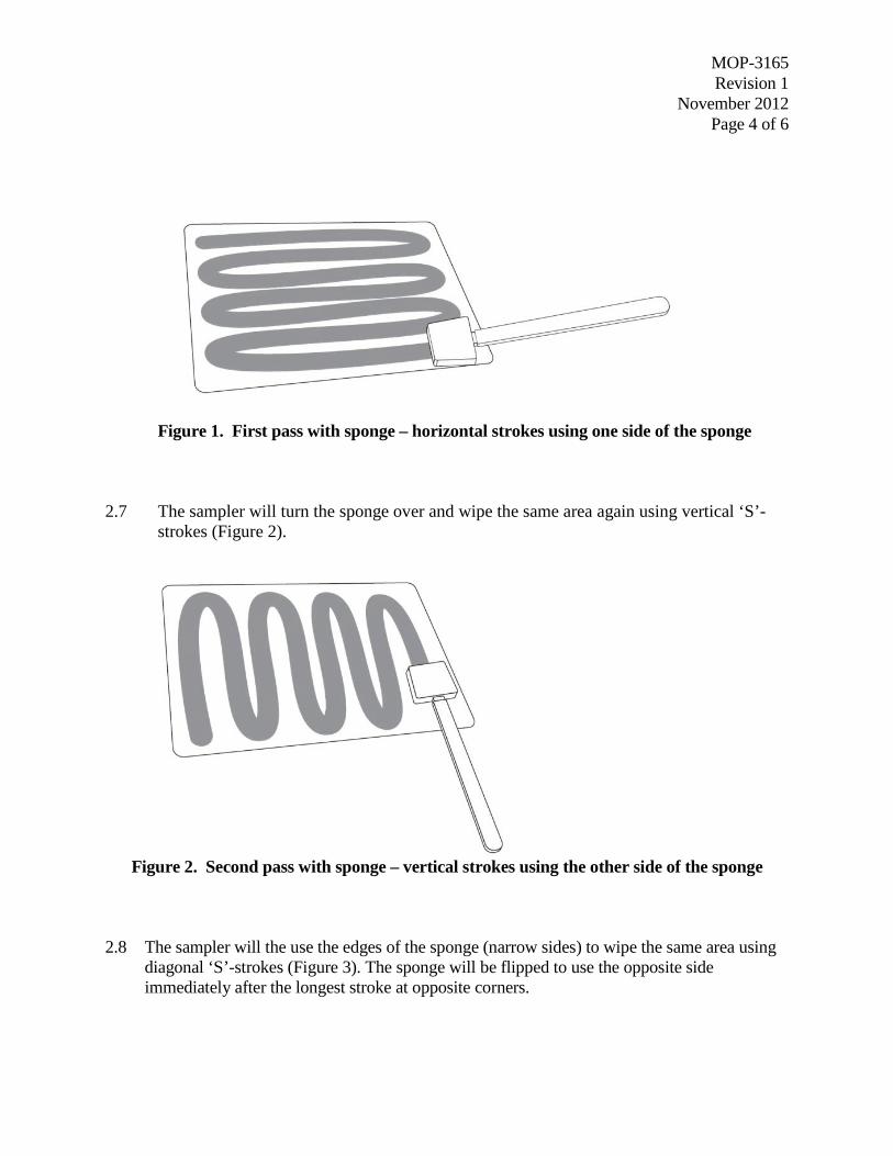
MOP-3165 Revision 1
November 2012 Page 4 of 6
Figure 1. First pass with sponge – horizontal strokes using one side of the sponge
2.7 The sampler will turn the sponge over and wipe the same area again using vertical ‘S’-strokes (Figure 2).
Figure 2. Second pass with sponge – vertical strokes using the other side of the sponge
2.8 The sampler will the use the edges of the sponge (narrow sides) to wipe the same area using diagonal ‘S’-strokes (Figure 3). The sponge will be flipped to use the opposite side immediately after the longest stroke at opposite corners.

MOP-3165 Revision 1
November 2012 Page 5 of 6
Figure 3. Third pass with sponge – diagonal strokes using the edges of the sponge
2.9 The sampler will use the tip of the sponge to wipe the perimeter of the sampling area
(Figure 4).
Figure 4. Final (fourth) pass with sponge – perimeter wipe using the tip of the sponge
2.10 The sample handler will open the stomacher bag, careful not to touch the inside of the bag.
2.11 The sampler will place the end of the sponge in the bag, holding the handle outside the opening of the bag.
2.12 The sample handler will grasp the sponge from outside of the bag, and help the sample break off the handle of the sponge. The handle below the thumbstop should not touch the inside of the stomacher bag.
2.13 The sample handler will securely seal the stomacher bag and wipe the outside with a disinfecting wipe.
2.14 The sample handler will then place the stomacher bag inside the unlabeled sterile bag.

MOP-3165 Revision 1
November 2012 Page 6 of 6
2.15 The sample handler will place this in the overpack bag and wipe the overpack bag with disinfecting wipes.
2.16 The sample handler will place the overpack bag in the sample bin.
NOTE: Remove excessive air from the re-sealable plastic bags to increase the number of
samples that can be shipped in one container.
2.17 The sampler will dispose of the template.
2.18 Both members will remove outer gloves and discard. Clean gloves should be worn for each new sample.
3.0 REFERENCES Sponge sample collection protocol adapted from:
National Validation Study of a Cellulose Sponge Wipe-Processing Method for Use after Sampling Bacillus anthracis Spores from Surfaces. Rose, Laura J.; Hodges, Lisa; O’Connell, Heather; Noble-Wang, Judith. Appl. Environ. Microbiol. 2011, 77(23):8355.

MOP 3168Revision 3
February 2013Page 2 of 17
MOP 3168
TITLE: AGGRESSIVE AIR SAMPLING (AAS) FOR WA 3-28: PHASE I SAMPLINGAPPROACH
SCOPE: This MOP outlines the setup, operation, and timeline schedule for conductingAAS testing in COMMANDER.
PURPOSE: To provide a standardized and repeatable procedure for all AAS tests to beconducted under WA 3-28’s Phase I sampling matrix using high volume (HiVol)samplers.
1.0 INTRODUCTION
Preparations for each test will be conducted according to the schedule listed in this procedure.
Any deviations will be noted in the laboratory notebook, along with the reason for the deviation.
Section 2.0 lists the preparation steps that need to be taken the Thursday before testing is to
occur (Day 1). Sections 3.0 and 4.0 detail the pre- and post-decon procedures to be followed for
AAS testing.
2.0 PREPARATION
NOTE: Materials needed before Day 1 include material coupons and gaskets, placed in
VHP bags, and exposed to a VHP sterilization cycle. These should be left to
degas for a minimum of 3 days before use.
Day 1 – Thursday
1. Ensure the following materials for inoculation are in airlock:
(2) 3 x 3 Grids
(6) ADAs and clamps for single coupons
(18) ADAs and clamps for 3 x 3 coupons
Oscillating fan
Tables for coupon staging come Monday

MOP 3168Revision 3
February 2013Page 3 of 17
2. Ensure all equipment needed for testing is in COMMANDER and COMMANDER is setup
(see Figure 1):
SAR inlet filter box, hoses and masks
(2) Blowers and needed power cords
(3) HiVol Samplers in open orientation (no air-tight seals)
HiVol samplers should have been calibrated the day prior
Hydrogen peroxide (H2O2) air monitors are calibrated and functional
Figure 1. COMMANDER layout showing HiVol sample numbers
3. Close and seal COMMANDER door.
4. Close airlock door.
5. VHP airlock per MOP-3120 (VHP Operation).
To airlock
Fan
HighVol – R1
HighVol – R2
HighVol – R3

MOP 3168Revision 3
February 2013Page 4 of 17
Day 2 – Friday
1. Aerate the airlock upon arrival in the morning.
2. VHP COMMANDER per MOP-3120 in the morning, so that external aeration can begin in
mid afternoon.
3. Clear the airlock for entry as early as possible using a Draeger tube.
4. Set up coupons in H130, outside of the enclosure, using equipment from the airlock and
previously sterilized coupons and gaskets allowed to degas in VHP bags.
5. Inoculate coupons according to MOP 6561 (Aerosol Deposition of Spores onto Material
Coupon Surfaces using the Aerosol Deposition Apparatus (ADAs)). Fill out Attachment B,
WA 3-28 Coupon Deposition Log. The list of coupon IDs follows, where M is the material
ID; L(Laminate), D(Drywall), or C(Carpet):
42” x 42” not inoculated 28-[test ID]-XM,
42” x 42” 28-[test ID]-M
14” x 14” material 28-[test ID]-M1-R[1,2,3]
14” x 14” stainless steel 28-[test ID]-S-R[1,2,3]
14” x 14” material not inoculated 28-[test ID]-XM1-F1
6. Calibrate the COMMANDER ATI H2O2 sensor outside of COMMANDER using MOP 3136
(General Procedure for Calibration of ATI Hydrogen Peroxide Gas Transmitters using
Solution Wells).
7. Place the ATI sensor back into COMMANDER.
8. Mop the enclosure with Clorox Clean-up.
9. Close enclosure doors.

MOP 3168Revision 3
February 2013Page 5 of 17
3.0 PRE-DECON AAS PROCEDURES
Day 3 - Monday
Conduct a pre-job safety briefing prior to initiating work.
A “buddy” equipped with appropriate respiratory protection is required to be present
outside of COMMANDER when personnel are working inside.
1. Set up the ELPI system from outside of COMMANDER and zero according to MOP 3133(Basic Operation and Maintenance of the Dekati Electrical Low Pressure Impactor (ELPI)).
2. Wipe down the outside of the 42” x 42” coupons, the 14” x 14” test coupons, and ADA’swith dispatch wipes.
3. Transfer the coupons from H130 to the airlock. This operation will be done with a clean teaminside the airlock, and a team in H130. The H130 team (in clean garb) will complete the wipedown, and then change garb. The airlock team will enter the airlock in clean garb andbooties. During the moving operation, the H130 team will pass the coupon to the airlockteam with no direct contact between alternate teams. Once both coupons have been passedinto the airlock, all personnel will leave the airlock, and it will be purged for 30 minutes. Anoscillating fan will be used to prevent settling.
4. Positive control 14” x 14” coupons should be moved at this same time, but put back in theiroriginal location. This is to simulate the movement undergone by the test coupons.
5. Verify the camera is recording, and that the DAS is operational and recording data.
6. Assemble the supplies:a. Sterilized PM10 filters (8)
b. Sterilized collection shims (8)
c. Sterile gloves (2 packs) and laboratory gloves
d. Sterile garb x 8(coat, p95, hair net, 12 boot covers)
e. EtO’d notebook, AAS event log and pen
f. Digital timer (2)
g. Duct tapeh. Blank sample kits (Filters Sample IDs : 28-05a-XAF-1-R(1-3), and 28-05a-XAF-
1-F1),( Shims Sample IDs : 28-05a-XAS-1-R(1-3) and 28-05a-XAS-1-F1)

MOP 3168Revision 3
February 2013Page 6 of 17
(Sponge sticks: 28-05a-M-1-R(1-3), 28-05a-XM-1-F1 28-05a-S-1-R(1-3)and 28-05a-S-1-F1)
i. Cooling vests
j. Dispatch wipes
k. Molykote® Grease Spray
l. Anemometer
7. Three personnel (referred to as “Clean Man”, “Dirty Man 1”, and Dirty Man 2”, or CM,DM1 and DM2) will enter the enclosure and wipe in bins of supplies, then close theenclosure doors.
- Plug in and record position of power cords for blowers and fans.
- Install the relative humidity (RH) and vaprous hydrogen peroxide (VHP) sensors tothe COMMANDER chamber.
- Verify supply quantities against the WA 28 packing list (found on DTRL/WA 3-28).
- ELPI should be monitoring enclosure PM, and should be changed to COMMANDERimmediately before entry.
- Personnel should spend 10 minutes minimum in enclosure before opening airlockdoor.
8. Three personnel (CM, DM1, and DM2) will enter the airlock wearing cooling vests, C-suitsand carrying the supply bins:
9. Once the airlock door is closed, open the door to COMMANDER. Put on clean garb over theC-suit. Install the sterile filters on top of the vents of the three HiVol samplers (vent seen inFigure 2a). To do this, the support person (DM1) will grab the filter frame with sterile glovesand hold it out of the way. The sample handler (DM2) will open the bag containing the filterand the sampler (CM) will use sterile thumb forceps to put the filter in place. The DM1 willthen return the frame and secure it in place. Unlatch the hinge of the head unit and pull down.Secure latches around the base of the unit (Figure 2b). CM can help with this last step beforechanging into new sterile gloves.
10. The DM1 will unwrap the aluminum foil covering the collection shim, leaving the shiminside and exposed. The DM2 will spray the shim with Molykote® Grease Spray, ensuringfull coverage of the shim. Wearing sterile gloves, the CM will aseptically pull the shim out ofthe foil and place in each of the three HiVol inlet heads, minimizing contact with the greasedsurface. Align the shim and secure in place with the Teflon tabs (Figure 2c).
11. CM will unlatch the top covering of the head unit and pull down. Secure in place with thelatches (Figure 2d).

MOP 3168Revision 3
February 2013Page 7 of 17
12. DM1 and DM2 will return to the airlock.
13. Wearing sterile gloves, the DM1 will remove the apparatus brace, ADAs, and gaskets fromthe sterile coupon and put aside in the airlock. DM1 and DM2 will pick up the coupon, beingcareful not to touch the surface. Move the coupon into COMMANDER and place in thedesignated sampling position. To do this, the coupon will need to be rotated vertically so thatit can fit through the door.
14. DM1 and DM2 remove their gowns and don SAR. The CM returns to the airlock and closesthe airlock door.
Inspect SAR masks and hoses and the filter box prior to donning.
a. b.

MOP 3168Revision 3
February 2013Page 8 of 17
c. d.
Figure 2. a) HiVol sampler with head unit and top open, and filter vent secured;b) head unit closed and latched; c) placement of shim; and d) top closed andlatched.
15. Turn on the fan to the 70% speed setting. Measure the wind speed at the HiVol inlets. Theseshould be less than 30 mph.
16. Test the force of the leaf blower, pointed away from the coupon, using the anemometer.
17. The DM1 will agitate the surface of the coupon using a leaf blower according to MOP 3166(Aerosolization of Contaminated Coupons Using the Toro Power Sweep Electric Blower forAggressive Air Sampling (AAS)). At the very moment the blower is turned on, DM2 will turnon all three HiVol samplers. DM2 will monitor the blowing time as per MOP 3166 anddocument the intervals by filling out the Aggressive Air Sampling (AAS) Event Log(Attachment A).
18. At the completion of the agitation, the DM1 and DM2 remain in COMMANDER. After 20minutes total (10 minutes after finishing aggressive agitation), DM2 turns off the HiVolsamplers.
19. Turn off (unplug) the fan.
20. CM will re-enter COMMANDER.

MOP 3168Revision 3
February 2013Page 9 of 17
21. Collect blank samples:
Filters Sample IDs : XAF-1-R(1-3) + XAF-1-F1 (Field blank)
Shims Sample IDs : XAS-1-R(1-3) + XAS-1-F1 (Field blank)
a. DM1 and DM2 don outer layer of clean garb.
b. The DM1 will open the first HiVol sampler and latch in it place.
c. The DM1 will don a pair of sterile gloves and remove the collection shim, being carefulnot to touch the sides of the flow ports.
d. The DM2 and CM will then use a sponge kit to sample the top surface of the shimaccording to MOP 3169 (Sponge Sample Collection Protocol for AAS Shims).
e. The DM1 will then discard the shim to the airlock for sterilization. The DM1 will unlatchthe base of the HiVol head unit and tilt the unit up to reveal the vent (see Figure 2a).
f. The DM1 will don a new pair of sterile gloves and remove the vent bracket and top grate,being careful not to touch the filter.
g. Donning new gloves, the CM will remove the filter using sterile thumb forceps. Fold thefilter in half and then in half again, keeping the top side of the filter inside of the fold.Using the forceps, transfer the filter directly to a stomacher bag. The DM2 will hold thestomacher bag open for this transfer.
h. Sample the shim plates and remove the filters for the two remaining HiVol samplersusing the same protocol.
22. Remove the blank coupon and place against the COMMANDER wall.
23. All personnel change into new sterile garb.
24. CM will install sterile filters on top of the vents of the three HiVol samplers and secure inplace. Unlatch the hinge of the head unit and pull down. Secure latches around the base ofthe unit.
25. The DM1 will unwrap the aluminum foil covering the collection shim, leaving the shiminside and exposed. The DM2 will spray the shim with Molykote® Grease Spray, ensuringfull coverage of the shim. Wearing sterile gloves, the DM2 will aseptically pull the shim out

MOP 3168Revision 3
February 2013Page 10 of 17
of the foil and place in each of the three HiVol inlet heads, minimizing contact with thegreased surface. Align the shim and secure in place with the Teflon tabs (see Figure 2c).
26. DM2 will unlatch the top covering of the head unit and pull down. Secure in place with thelatches.
27. Personnel will return to the airlock and DM1 and DM2 will don 3 pairs of boot covers.
28. Wearing gloves, the DM1 will remove the apparatus brace, ADAs, and gaskets from theinoculated coupon and put aside in the airlock. DM1 and DM2 will pick up the coupon, beingcareful not to touch the inoculated surface, and move the coupon into COMMANDER andplace in the designated sampling position. DM1 and DM2 will remove one pair of bootcovers while crossing the threshold into COMMANDER with the help of CM.
29. In the same aseptic manner, remove ADAs from material coupons and place inside onCOMMANDER floor just above the test coupon, removing a second pair of boot coverswhile entering COMMANDER. This process will make one large 42” x 56” coupon.
30. The DM1 and DM2 remove their gowns and don SAR. CM closes the airlock door.
31. CM communicates to the buddy outside to unplug blowers 2 and 3. Confirm this is done toDM2. Alternatively, the CM can unplug as he leaves the airlock.
32. DM2 then plugs in blowers 2 and 3 (now, or after the 12 minute AAS operation).
33. DM2 turns on the fan to the 70% speed setting.
34. Agitate the surface of the inoculated coupon according to MOP 3166. At the very momentthe blower is turned on, a DM2 will turn on the first HiVol sampler as specified in the QAPP.The DM2 will monitor the blowing time as per MOP 3166 and document the intervals byfilling out the AAS Event Log.
35. When agitation is complete, remove SAR and leave in COMMANDER.
36. CM to exit airlock, leaving clean garb in the airlock upon exit.
37. DM 1 and DM2 will open the airlock door, move to the airlock and close the airlock door.
38. DM1 and DM2 will shower out and exit the airlock.

MOP 3168Revision 3
February 2013Page 11 of 17
39. After 20 minutes of air sampling, turn off the first HiVol sampler. Immediately turn on thesecond sampler.
40. After 20 minutes of sampling with the second HiVol sampler, turn off the second samplerand immediately turn on the third. Again, sample for 20 minutes and then turn off.
41. Wearing clean garb, collect samples from the stainless steel and laminate control couponsaccording to MOP 3165 (Sponge Sample Collection Protocol). A blank laminate coupon (L1-F1) and a field blank for sponge sticks (S1-F1) should also be sampled at this time.
Reference Positives IDs : S-1-R(1-3), L1-R(1,2,3), L1-F1, and S1-F1
42. VHP airlock and start aeration as soon as possible (MOP-3120). Allow 18 hours for theagitated spores to settle in COMMANDER.
Day 4 – Tuesday
1. Verify the camera is recording, and that the DAS is operational and recording data.
2. After waiting the specified spore-settling time, a three-person sampling team (CM, DM1,and DM2) will enter COMMANDER in C-suits carrying :
a. Sterile gloves and laboratory gloves
b. Sterile garb (coat, p95, hair net, 8 boot covers)
c. EtO’d notebook, AAS event log and pen
d. Digital timer
e. Duct tape
f. Sample kits: Kits: 28-05a-MAF-1-R{1-3) and 28-05a-MAF-1-F128-05a-MAS-1-R{1-3) and 28-05a-MAS-1-F1
g. Dispatch wipes
3. Each will don sterile garb and boot covers.
4. Enter COMMANDER, removing one pair of boot covers while crossing the threshold.
5. Remove the air filters from the HiVol samplers. The team will consist of a CM, DM2 and aDM1.

MOP 3168Revision 3
February 2013Page 12 of 17
Filter Sample IDs: MAF-1-R(1-3), where M is material ID – C-carpet, L-laminate, andW-drywall
Shim Sample IDs: MAS-1-R(1-3), where M is material ID – C-carpet, L-laminate, andW-drywall
6. The DM1 will open the first HiVol sampler and latch in it place.
7. The DM1 will don a pair of sterile gloves and remove the collection shim, being careful notto touch the sides of the flow ports.
8. The DM2 and CM will then use a sponge kit to sample the top surface of the shim accordingto MOP 3169 (Sponge Sample Collection Protocol for AAS Shims). CM will manipulate thesponge stick.
9. The DM1 will then discard the shim into the airlock for disinfection. The DM1 will unlatchthe base of the head unit and tilt the unit up to reveal the vent.
10. The DM1 will don a new pair of gloves and remove the vent bracket and top grate, beingcareful not to touch the filter.
11. Donning new gloves, the CM will remove the filter using sterile thumb forceps. Fold thefilter in half and then in half again, keeping the top side of the filter inside of the fold. Usingthe forceps, transfer the filter directly to a stomacher bag. The DM2 will hold the stomacherbag open for this transfer.
12. Sample the shim plates and remove the filters for the two remaining HiVol samplers usingthe same protocol.
13. All HiVol samplers should be in the fully open position.
14. All personnel shower out of the airlock.
15. VHP COMMANDER as per MOP 3120. Conditions will be determined by the WAM.
16. Start aeration of COMMANDER.
17. VHP the airlock as per MOP 3120.

MOP 3168Revision 3
February 2013Page 13 of 17
4.0 POST-DECON AAS PROCEDURES
Day 5 - Wednesday
1. Start airlock aeration as soon as possible and ensure conditions are safe for entry.
2. Verify the camera is recording, and that the DAS is operational and recording data.
3. Three personnel will enter the airlock wearing C-suits and carrying:
a. Sterilized PM10 filters (3)
b. Sterilized collection shims (3)
c. Sterile gloves and laboratory gloves
d. Sterile garb (coat, p95, hair net, boot covers)
e. EtO’d laboratory notebook, AAS event log and pen
f. Digital timer
g. Duct tape
h. Dispatch wipe
i. Sample kits Sponge stick kits 28-05a-L-2-R(1-3) and 28-05a-L-2-F1
4. Once the airlock door is closed, open the door to COMMANDER. Don boot covers (2 pairs),being careful not to contaminate the first pair with the airlock floor.
5. Move into COMMANDER, removing one pair of boot covers when crossing the threshold.
6. Collect post-decon sponge stick surface samples (or vacuum sock samples of carpet coupons)of the three positive coupons per MOP 3165. CM will serve as the sampler, DM1 will serveas the support person.
Sample IDs: M-2-R(1-3), where M is material type as listed above
7. DM2 will place coupons in soapy water in airlock after sampling.
8. All personnel to change into new clean garb.
9. CM will install the sterile filters on top of the vents of the HiVol samplers and secure inplace. DM2 will unlatch the hinge of the head unit and pull down. Secure latches around thebase of the unit.

MOP 3168Revision 3
February 2013Page 14 of 17
10. The DM1 will unwrap the aluminum foil covering the collection shim, leaving the shiminside and exposed. The DM2 will spray the shim with Molykote® Grease Spray, ensuringfull coverage of the shim. Wearing sterile gloves, the DM2 will aseptically pull the shim outof the foil and place in each of the three HiVol inlet heads, minimizing contact with thegreased surface. Align the shim and secure in place with the Teflon tabs (see Figure 2c).
11. The DM1 and DM2 will remove their gowns and don SAR, while CM retires to airlock.
12. CM to communicate to buddy outside to verify Blower 1 power cord is plugged in, andBlowers 2 and 3 are off.
Inspect the SAR masks and hoses and the filter box prior to donning.
13. Turn on the fan to the 70% speed setting. Measure the wind speed at the HiVol inlets. Theseshould be less than 30 mph.
14. Test the force of the leaf blower, pointed away from the coupon, using the anemometer.
15. Agitate the surface of the coupon according to MOP 3166. At the very moment the blower isturned on, DM2 will plug in the first HiVol sampler. The DM2 will monitor the blowing timeas per MOP 3166 and document the intervals by filling out the AAS event log.
16. When agitation is complete, DM1 and DM2 move to airlock, remove SAR and drop theirhose and mask in COMMANDER, close the airlock door and shower out of theCOMMANDER airlock.
17. After 20 minutes of air sampling, turn off the first HiVol sampler. Immediately turn on thesecond sampler.
18. After 20 minutes of sampling with the second HiVol sampler, turn off the second samplerand immediately turn on the third. Again, sample for 20 minutes and then turn off.
19. Allow chamber to settle for 2 hours.
20. After the settling time, a three-person sampling team will enter COMMANDER carryingpost-decon sample kits: filter kits 28-05a-LAF-2-R{1-3) and 28-05a-LAF-2-F1 and shimkits 28-05a-LAS-2-R{1-3) and 28-05a-LAS-2-F1
21. Sample the collection shims and collect the filters.
Filter Sample IDs: MAF-2-R(1-3), where M is material code , listed above
Shim Sample IDs: MAS-2-R(1-3), where M is material code , listed above
MOP 3168Revision 3
February 2013Page 15 of 17
a. The DM1 will open the first HiVol sampler and latch in it place.
b. The DM1 will don a pair of sterile gloves and remove the collection shim, beingcareful not to touch the sides of the flow ports.
c. The DM2 and CM will then use a sponge kit to sample the top surface of the shimaccording to MOP 3169.
d. The DM1 will then discard the shim to the airlock. The DM1 will unlatch the base ofthe head unit and tilt the unit up to reveal the vent.
e. The DM1 will don a new pair of gloves and remove the vent bracket and top grate,being careful not to touch the filter.
f. Donning new gloves, the CM will remove the filter using sterile thumb forceps. Foldthe filter in half and then in half again, keeping the top side of the filter inside of thefold. Using the forceps, transfer the filter directly to a stomacher bag. The DM2 willhold the stomacher bag open for this transfer.
g. Sample the shim plates and remove the filters for the two remaining HiVol samplersusing the same protocol.
22. Conduct post-test flow calibration as outlined in MOP 3170 (HiVol Calibration Check).
23. Verify that two blowers are placed in COMMANDER and that the samplers are opened.Ensure all SAR related equipment is located in COMMANDER.
24. Exit COMMANDER and shower out of the airlock.
25. VHP COMMANDER per MOP-3120.

MOP 3168Revision 3
February 2013Page 16 of 17
Attachment A
Aggressive Air (AA) Sampling Event Log
Test ID ______________
Agitator
DM2
Buddy 2
Reference:
Dimensions(in2)
AgitationTime (s)
HorizontalSweeps
VerticalSweeps
Sweeprate
(s/sweep)
14 x 14 60 10 10 3
28 x 28 240 20 20 6
42 x 42 540 30 30 9
Test Day/date
Coupon ID High Vol 1start
High Vol2 start
High Vol 3start
2/SterileBlank
2/ Test
4/ Test
Test Day/date
Coupon ID Verticalstart
Verticalend
# sweeps Horizontalstart
Horizontalend
#sweeps
2/SterileBlank 30 30
2/ Test 30 30
3/ Positive 1 10 10
3/ Positive 2 10 10
3/ Positive 3 10 10
4/ Test 30 30

MOP 3168Revision 3
February 2013Page 17 of 17
Attachment B
WA 3-28 Coupon Deposition Log Page ____ of ___
Test ID MDI ID:
Date Initial Weight (g):Personnel / Title Final Weight (g):
TimeCouponID Vortex Interval (s) Puff Number
MDIWeight (g) Comments

MOP 6535a Revision 4
January 2013 Page 1 of 8
Miscellaneous Operating Procedure (MOP) 6535a:
Serial Dilution: Spread Plate Procedure to Quantify Viable Bacterial Spores
Prepared by: __________________________________________ Date: 2/11/2013 Nicole Griffin Gatchalian, ARCADIS Work Assignment Leader
Reviewed by: __________________________________________ Date: 2/11/2013 Dahman Touati, ARCADIS Project Manager
Approved by: __________________________________________ Date: 2/11/2013 Worth Calfee, EPA Work Assignment Manager
Prepared for
National Homeland Security Research Center Office of Research and Development
U.S. Environmental Protection Agency Research Triangle Park, NC 27711
Prepared by
ARCADIS U.S., Inc.
4915 Prospectus Drive, Suite F Durham, NC 27713

MOP 6535a Revision 4
January 2013 Page 2 of 8
MOP 6535a TITLE: SERIAL DILUTION: SPREAD PLATE PROCEDURE TO QUANTIFY
VIABLE BACTERIAL SPORES
SCOPE: Determine the abundance of bacterial spores in a liquid extract
PURPOSE: Determine quantitatively the number of viable bacterial spores in a liquid suspension using the spread plate procedure to count colony-forming units (CFU)
Materials: • Liquid suspension of bacterial spores
• Sterile centrifuge tubes
• Diluent as specified in QAPP or Test Plan (e.g., sterile water, Phosphate Buffered Saline with Tween 20 (PBST))
• Media plates as specified in QAPP or Test Plan (e.g., Trypticase Soy Agar (TSA) plates)
• Microliter pipettes with sterile tips
• Sterile beads placed inside a test tube (used for spreading samples on the media surface according to MOP 6555 (Petri Dish Media Inoculation Using Beads) or cell spreaders
• Vortex mixer 1.0 PROCEDURE (This protocol is designed for 10-fold dilutions.) 1. For each bacterial spore suspension to be tested label microcentrifuge tubes as follows: 10-1,
10-2, 10-3, 10-4, 10-5, 10-6... (The number of dilution tubes will vary depending on the concentration of spores in the suspension). Aseptically, add 900 uL of sterile diluent to each of the tubes.
2. Label three media plates for each dilution that will be plated. These dilutions will be plated in triplicate.
3. Mix original spore suspension by vortexing thoroughly for 30 seconds. Immediately after the
cessation of vortexing, transfer 100 uL of the stock suspension to the 10-1 tube. Mix the 10-1 tube by vortexing for 10 seconds, and immediately pipette 100 uL to the 10-2 tube. Repeat this process until the final dilution is made. It is imperative that used pipette tips be exchanged for a sterile tip each time a new dilution is started.
4. To plate the dilutions, vortex the dilution to be plated 10 seconds, immediately pipette 100
uL of the dilution onto the surface of a media plate, taking care to dispense all of the liquid

MOP 6535a Revision 4
January 2013 Page 3 of 8
from the pipette tip. If less than 10 seconds elapses between inoculation of all replicate plates, then the initial vortex mixing before the first replicate is sufficient for all replicates of the sample. Use a new pipette tip for each set of replicate dilutions.
5. Carefully and aseptically spread the aliquotted dilution on the surface of the media either by
use of glass beads (MOP 6555) or cell spreader (the method used may be directed in the QAPP or Test Plan) until the entire sample is distributed on the surface of the agar plate. Repeat for all plates.
6. Incubate the plates for the optimum time period at the optimum growth temperature for the
target organism (incubation conditions will vary depending on the organism’s optimum growth temperature and generation time. This information can be found in Bergey’s Manual of Determinative Bacteriology or it will be provided with the ATCC certification.
7. Manually enumerate the colony forming units (CFU) on the media plates by manually
counting with the aid of a plate counting lamp and a marker (place a mark on the surface of the Petri dish over each CFU when counting, so that no CFU is counted twice). A hand held tally counter or an electronic counting pen may be used to assist the person counting, but may not be used as the primary source for the count. Quality control (QC) requirements for bacterial enumeration will be addressed per QAPP or test plan. However, in general, the following QC practices should always be adhered to: a. The arrangement of plates and tubes, and the procedure for preparing dilutions and
enumerating CFU should be done the exact same way each time. This helps prevent systematic errors and often helps determine the cause of problems when a discrepancy is found.
b. A visual check of the graduated pipette tip should be made during each use to ensure the pipette is pulling properly.
c. Samples should acclimate to room temperature for 1 hour prior to plating.
d. Samples should be processed (extracted and plated) from the least contaminated to the most contaminated.
e. When a target range of CFU is known, three dilution factors are plated to bracket the expected results (0, -1, and -2, if the -1 dilution factor was the target).
f. Enumerated colonies and results should be verified that the results are the target organism, and that second counts have been performed. Second counts must be completed on 25% of significant data, and must be within 10% of the first count. If CFUs are found to have more than a 10% difference between first and second counts, then a third count is to be completed.

MOP 6535a Revision 4
January 2013 Page 4 of 8
g. Pictures should be taken of any plates that are contaminated or have results out of the normal
8. Record all quantitative data in the “Serial Dilution/Plating Results Sheet”. Target range for statistically significant counts is 30-300 CFU. Data that fall out of the 30-300 CFU range are addressed in MOP 6584 (Procedure for Replating Bacteria Spore Extract Samples) and MOP 6565 (Filtration and Plating of Bacteria from Liquid Extracts).
2.0 CALCULATIONS Total abundance of spores (CFU) within extract:
(Avg CFU / volume (mL) plated) X (1 / tube dilution factor) X extract volume For example: Tube Dilution Volume plated Replicate CFU 10-3 100 µL (0.1 mL) 1 150 10-3 100 µL (0.1 mL) 2 250 10-3 100 µL (0.1 mL) 3 200
Extract total volume = 20 mL
(200 CFU / 0.1 mL) X (1/10-3) X 20 mL =
(2000) X (1000) X 20 = 4.0 X 10⁷ CFU
Note: The volume plated (mL) and tube dilution can be multiplied to yield a ‘decimal factor’ (DF). DF can be used in the following manner to simplify the abundance calculation.
Spore Abundance per mL = (Avg CFU) X (1 / DF) X extract volume
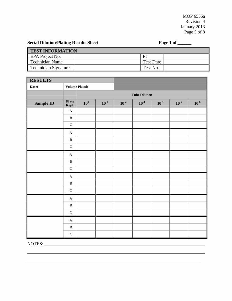
MOP 6535a Revision 4
January 2013 Page 5 of 8
Serial Dilution/Plating Results Sheet Page 1 of ______
TEST INFORMATION EPA Project No. PI Technician Name Test Date Technician Signature Test No.
RESULTS Date: Volume Plated:
Tube Dilution
Sample ID Plate Repl. 100 10-1
10-2 10-3
10-4 10-5 10-6
A B C
A B C
A B C
A B C
A B C
A B C
NOTES:

MOP 6535a Revision 4
January 2013 Page 6 of 8
Page 2 of ______
Sample ID Plate Repl. 100 10-1
10-2 10-3
10-4 10-5 10-6
A B C
A B C
A B C
A B C
A B C
A B C
A B C
A B C
A B C
A B C
NOTES:

MOP 6535a Revision 4
January 2013 Page 7 of 8
Page _____ of ______
Sample ID Plate Repl. 100 10-1
10-2 10-3
10-4 10-5 10-6
A B C
A B C
A B C
A B C
A B C
A B C
A B C
A B C
A B C
A B C
NOTES:

MOP 6535a Revision 4
January 2013 Page 8 of 8
Page _____ of ______
Sample ID Plate Repl. 100 10-1
10-2 10-3
10-4 10-5 10-6
A B C
A B C
A B C
A B C
A B C
A B C
A B C
A B C
A B C
A B C
NOTES:

MOP 6555Revision 2
November 2012Page 1 of 4
Miscellaneous Operating Procedure (MOP) 6555:
Petri Dish Media Inoculation Using Beads
Prepared by: __________________________________________ Date: 11/15/2012Nicole Griffin Gatchalian, ARCADIS Work Assignment Leader
Reviewed by: __________________________________________ Date: 11/15/2012Dahman Touati, ARCADIS Project Manager
Approved by: __________________________________________ Date: 11/15/2012Worth Calfee, EPA Work Assignment Manager
Prepared for
National Homeland Security Research CenterOffice of Research and Development
U.S. Environmental Protection AgencyResearch Triangle Park, NC 27711
Prepared by
ARCADIS U.S., Inc.4915 Prospectus Drive, Suite F
Durham, NC 27713

MOP 6555Revision 2
November 2012Page 2 of 4
MOP 6555
TITLE: PETRI DISH MEDIA INOCULATION USING BEADS
SCOPE: This MOP outlines the procedure for cleaning, assembling, and using beads toinoculate agar plates.
PURPOSE: To provide an easily repeatable method for spreading liquid inoculation ontoagar plates.
Equipment:
#13 test tubes
6 x 12 test tube racks (which hold 72 tubes)
Beads of various sizes (glass)
Glass autoclavable trays (stainless steel is eventually corroded by the bleach andautoclaving processes)
Bleach
DI water
Hot gloves
Amber bottle for collecting hazardous waste (with hazardous waste label)
Funnel
Aluminum foil
Label tape
Chemical hood
Autoclave
Oven
Labeled bead container or cup (All mold and bacteria beads must be kept separately)
1.0 CLEANING BEADS
1. When a sufficient number of beads have been collected, or at least once a day whenbeads are being used to spread colonies, place the used beads into a tray with a solutioncontaining a 1:5 ratio of bleach to deionized water.
Add the bleach to the beads first, under the protection of a chemical safety cabinet. Then

MOP 6555Revision 2
November 2012Page 3 of 4
add the deionized water. Cover the pan with aluminum foil and label it with thecontents (for example: “bacteria beads in 1:5 bleach to DI water solution”). Soak thebeads 12-24 hours (usually overnight) in a chemical fume hood.
2. After soaking, take a bottle brush and thoroughly scrub the beads.
3. Decant the bleach solution (collect the bleach for proper disposal) and rinse withdeionized water 6 to 8 times, collecting the rinsate after the first rinse for disposal(subsequent rinses can be discarded in the lab sink). Rinse until the decanted liquid isclear. Use a funnel to add the bleach waste to a labeled amber waste bottle. Theseliquids must be labeled “hazardous waste” and can then be stored, collected or disposedof properly.
4. Cover the beads with deionized water and autoclave for 1 hour on the liquid cycle.
5. Decant the deionized water and place the tray of beads in the Thelco lab oven at 121 Cuntil dry (a minimum of 3 hours).
6. Remove the beads from the oven using proper safety equipment (heat gloves) and coverwith clean aluminum foil to prevent contamination. Label each tray with the followinginformation:
“Clean bacteria (or mold) beads,” the date beads were cleaned, initials of the personwho cleaned them.
7. These beads are then ready for use as described in “PLACING BEADS IN TUBES”.
3.0 PLACING BEADS IN TUBES
1. Fill a 6 x 12 rack with tubes
2. Place clean beads into a shallow pan, and then manually fill each tube with 7-15beads/tube.
Note: Beads vary in size and will therefore fill the tubes to different heights.
3. Tightly attach a cap to each tube
4. Autoclave for 1 hour using a gravity sterilization cycle (see MOP 6570). Autoclave tapemust be placed on the top of each rack to provide evidence that the beads have beensterilized

MOP 6555Revision 2
November 2012Page 4 of 4
4.0 SPREADING BEADS
1. To spread inoculum on the agar surface, one tube of beads should be used for eachindividual plate.
2. After the beads have been added, the plates can be stacked up to six plates high. Theplates are then shaken 10 times from side-to-side. Turn the stack of plates ¼ turn, andagain shake 10 times from side-to-side. Repeat this procedure (¼ turn and 10 shakes) twomore times, so that the beads are shaken a total of forty times.
3. Turn the plates over (upside down), and tap the beads into the lid.
4. Aseptically dump the beads into a labeled bead container (mold and bacteria beads mustbe labeled and collected separately), which should be considered contaminated one plateat a time, replacing the lid as quickly as possible to prevent contamination.
References
1. http://serc.carleton.edu/microbelife/k12/LIMW/dilution.html
2. http://www.qbiogene.com/businessdivisions/platformnews/news0005-b.shtml
3. http://www.genlantis.com/objects/catalog/Product/extras/C400050.pdf
4. EPA - SHEM Chemical Hygiene Plan
MOP 6562Revision 1
February 2013Page 1 of 6
Miscellaneous Operating Procedure (MOP) 6562:
Preparing Pre-Measured Tubes with Aliquoted Amounts ofPhosphate Buffered Saline with Tween 20 (PBST)
Prepared by: __________________________________________ Date: 2/12/2013Nicole Griffin Gatchalian, ARCADIS Work Assignment Leader
Reviewed by: __________________________________________ Date: 2/12/2013Dahman Touati, ARCADIS Project Manager
Approved by: __________________________________________ Date: 2/12/2013Worth Calfee, EPA Work Assignment Manager
Prepared for
National Homeland Security Research CenterOffice of Research and Development
U.S. Environmental Protection AgencyResearch Triangle Park, NC 27711
Prepared by
ARCADIS U.S., Inc.4915 Prospectus Drive, Suite F
Durham, NC 27713

MOP 6562Revision 1
February 2013Page 2 of 6
MOP 6562
TITLE: PREPARING PRE-MEASURED TUBES WITH ALIQUOTED AMOUNTSOF PHOSPHATE BUFFERED SALINE WITH TWEEN 20 (PBST)
SCOPE: This MOP provides the procedure for preparing PBST.
PURPOSE: This procedure will ensure that that the PBST is prepared correctly and that allmeasured tubes are filled aseptically.
1.0 PREPARING STERILE PHOSPHATE BUFFERED SALINE WITH TWEEN 20(PBST)
Phosphate Buffered Saline with Tween 20 (PBST) is prepared 1 L at a time in a 1 L flask.
1. Add 1 packet of SIGMA Phosphate Buffered Saline with Tween 20 (P-3563) to 1 L ofdeionized (DI) water.
2. Shake vigorously to mix until dissolved.
3. Label bottle as “non-sterile PBST” and include date and initials of person who madePBST.
4. Filter sterilize into two 500 mL reagent bottles using 150 ml bottle top filter (w/ 33mmneck and .22 µm cellulose acetate filter) for sterilization. Complete this by pouring theliquid into the non-sterile PBST into the top portion of the filtration unit 150 ml at a time,while using the vacuum to suck the liquid through the filter. Continue to do this until 500ml have been sterilized into a 500 ml bottle. Change bottle top filter units between eachand every 500 ml bottle.
5. Change label to reflect that the PBST is now sterile. Include initials and date ofsterilization. The label should now include information on when the PBST was initiallymade and when it was sterilized and by whom.
6. Each batch of PBST should be used within 90 days.
2.0 PREPARING 20 ML/5 ML PBST TUBES FOR USE DURINGEXPERIMENTATION
Twenty (20) ml or five (5) ml of the prepared PBST will be added to each sterile 50-mlconical tube as detailed below. Each flat of conical tubes contains 25 tubes, so one 500 mlsterile bottle of PBST should fill approximately one flat when 20 ml tubes are needed andfour flats when 5 ml tubes are needed.

MOP 6562Revision 1
February 2013Page 3 of 6
1. Prepare the hood by wiping down with ethanol, followed by bleach, followed by DI waterand a clean Kimwipe or Techwipe. Then stock the hood with the following items if theyare not already there:
- The flats of sterile conical tubes you need to fill with PBST.- Sufficient bottles of sterile PBST to fill these tubes.- Ample 25 ml serological pipettes (at least 3 per flat) for 20 ml transfers and 10
ml serological pipettes for the 5 ml transfers.- Serological pipetter (automatic, hand-held pipette).- Burner and striker.
2. Light the burner and adjust the flame for a width adequate to flame the lips of the PBSTbottles.
3. Take one flat of sterile conical tubes and loosen each cap on the outside edges (about ½turn).
4. Open a serological pipette and insert into the serological pipetter, taking care to not touchthe tip to any surface.
5. Hold the pipetter with the first three fingers of your right (or dominant) hand. With yourleft hand (or non-dominant hand), pick up a bottle of the PBST and use the bottom ofyour right hand to unscrew the lid. Place the lid upside down on the benchtop andquickly flame the lip of the bottle. Turn the bottle and repeat, taking care to thoroughlyflame the lip without getting the glass so hot that it shatters.
6. Inset the tip of the pipette into the bottle and fill to the 20 ml line. Flame the bottle lipand place the bottle on the benchtop.
NOTE: If the tip of the pipette touches the outside of the bottle or any othersurface in the hood, consider it contaminated. Discard the pipetteand reload a new one.
7. Quickly pick up one of the tubes that you have loosened the cap on, and use the bottomof your right hand to remove the cap. Completely discharge the entire pipette into thetube, taking care to not touch anything with the tip of the pipette. Recap the tube andplace back into the flat (the lid does not have to be tight – you will tighten the lids afteryou have completed filling the 10 outside tubes).
NOTE: If the tip touches the outside or rim of the tube (or any other surfacein the hood), consider the tube and pipette contaminated. Discardboth the tube and the pipette.

MOP 6562Revision 1
February 2013Page 4 of 6
8. Pick up the PBST bottle and flame the lip. Repeat Steps 6 and 7 until all 10 of the tubeson the outside of the flat have been filled. Flame the lip of the PBST bottle and replacethe cap. Slide the used pipette back into the plastic sleeve and put to the side of the hoodfor disposal. Then tighten the lid of each tube you just filled. But rather than placing itback into its original spot in the flat, switch it for the empty tube from the next row.When this has been completed, go around the outside of the flat again and loosen the lidsof these 10 tubes. Repeat steps 4 through 7 to fill and cap these tubes.
9. This same procedure is used to fill the middle row of tubes from the flat, and if morethan one flat of tubes is being filled, can be done at the same time as the outside rows of asecond flat.
10. When all tubes have been filled, label each flat as follows, and place on the shelf in roomE390B:
“PBST Tubes (20 ml or 5 ml)”Date preparedYour initials
11. These tubes should be made at least 14 days before they need to be used so that they canbe verified as sterile. Any tubes that are cloudy or that have any floating matter/turbidityshould be discarded. The tubes are stable for and should be used within 90 days.
3.0 CLEANUP FOR 20 ML/5 ML PBST TUBES
1. Dispose of the used pipettes in the nonregulated waste.
2. Plug in the serological pipetter so that it can recharge.
3. Replace any unused PBST in the liquid containment on the shelf. Make sure that thebottle is labeled as having been opened (date opened and initials of whomever used it).
4. Turn off the burner.
5. Wipe down the hood benchtop with ethanol, followed by bleach, followed by DI waterand a clean Kimwipe or TechWipe.
4.0 PREPARING 900µL PBST TUBES FOR USE DURING EXPERIMENTATION
1. Prepare the hood by wiping down with ethanol, followed by bleach, followed by DI waterand a clean Kimwipe or Techwipe. Then stock the hood with the following items if theyare not already there:

MOP 6562Revision 1
February 2013Page 5 of 6
- A sterile beaker of microcentrifuge tubes.- Sufficient tubes of sterile PBST to fill these tubes (PBST may be aseptically
transferred to 50 ml conical tubes for an easier aseptic transfer to themicrocentrifuge tubes- it is easier than working from a 500 ml reagent bottle.Make certain that these 50 ml conical tubes are labeled to when the PBST wasmade, sterilized, etc.).
- 1000 µL micropipette.- 1000 µL sterile pipette tips- Microcentrifuge tube racks.- Labeled beaker or waste container used to hold non-regulated waste, such as
tips, under the hood.
2. Carefully remove the microcentrifuge tubes one at a time from the beaker and close thetop on each one before placing it in the tube rack. Place the tubes in the rack skippingevery other row. Fill up two racks doing this.
3. Add 900 µL of PBST to the microcentrifuge tubes by aseptically transferring the PBSTfrom the sterile 50 ml conical tube containing the PBST. Do this by using the 1000 µLmicropitte and tips. Change tips whenever after two rows of tubes are completed orwhenever a contamination event (such as touching the outside of the 50 ml tube or themicrocentrifuge tube) occurs. Put the dirty tips in the beaker or container used to containwaste (tips, tubes) in the hood. If any 900 µL tubes are contaminated during the transfer,dispose of them in the waste container used to hold tips under the hood. If a new box oftips has to be opened, make certain the date it was opened and initials of the person whoopened it are clearly labeled on the box.
4. After both racks are full, carefully move all the tubes from one rack to fill in the emptyrows on the other rack. In this manner, one rack should be completely filled with tubes atthis point.
5. Label the rack of tubes as “Sterile 900 µL PBST Tubes”, along with the name of theperson who completed the transfer, along with the date. Also, include the date that theoriginal stock of PBST was made and the date it was sterilized, along with the initials ofthe person who completed those steps.
5.0 CLEANUP FOR 900µL PBST TUBES
1. Dispose of the waste that was put in the labeled beaker or waste container (micropipettetips and tubes) in the nonregulated waste. Then, place this beaker in the “To bedecontaminated via sterilization- contaminated glassware” bin or if it is a disposablecontainer, then it can be put in the non-regulated waste container.
2. Put the unused sterile tips and the micropipetter back in its original location.

MOP 6562Revision 1
February 2013Page 6 of 6
3. Replace any unused 50 ml conicals of PBST in the liquid containment on the shelf.Make sure that the tube is labeled as having been opened (date opened and initials ofwhomever used it). If the tube could possibly be contaminated in any way, dispose of itin non-regulated waste.
4. Wipe down the hood benchtop with ethanol, followed by bleach, followed by DI waterand a clean Kimwipe or TechWipe.

MOP 6563Revision 2
November 2012Page 1 of 6
Miscellaneous Operating Procedure (MOP) 6563:
Swab Streak Sampling and Analysis
Prepared by: __________________________________________ Date: 11/15/2012Nicole Griffin Gatchalian, ARCADIS Work Assignment Leader
Reviewed by: __________________________________________ Date: 11/15/2012Dahman Touati, ARCADIS Project Manager
Approved by: __________________________________________ Date: 11/15/2012Worth Calfee, EPA Work Assignment Manager
Prepared for
National Homeland Security Research CenterOffice of Research and Development
U.S. Environmental Protection AgencyResearch Triangle Park, NC 27711
Prepared by
ARCADIS U.S., Inc.4915 Prospectus Drive, Suite F
Durham, NC 27713

MOP 6563Revision 2
November 2012Page 2 of 6
MOP 6563
TITLE: SWAB STREAK SAMPLING AND ANALYSIS
SCOPE: This MOP provides the procedure for the process of completing a swab streakplate and subsequent qualitative analysis.
PURPOSE: This procedure will ensure that the swab streak plate sampling and analysismethods are standardized and that the collection and plating of samples arefree from contamination.
1.0 PREPARING THE MATERIALS
There are two types of prepared swabs that can be used in this procedure:
Environmental Transport Swabs – purchased swabs that are individually packagedand pre-sterilized.
In-house Sterilized Swabs – swabs placed into autoclave pouches and sterilizedusing a 1-hour gravity cycle.
This procedure requires the following materials and equipment:
Tryptic soy agar (TSA) media plates
32 C incubator
Nitrile (non-sterile) gloves
Sharpie for writing on plates
2.0 COLLECTING AND PLATING SAMPLES
The procedure for collecting and plating samples is dependent on the type of swab beingused. Appropriate PPE should be worn in both cases and includes a lab coat, nitrile gloves,and safety glasses.
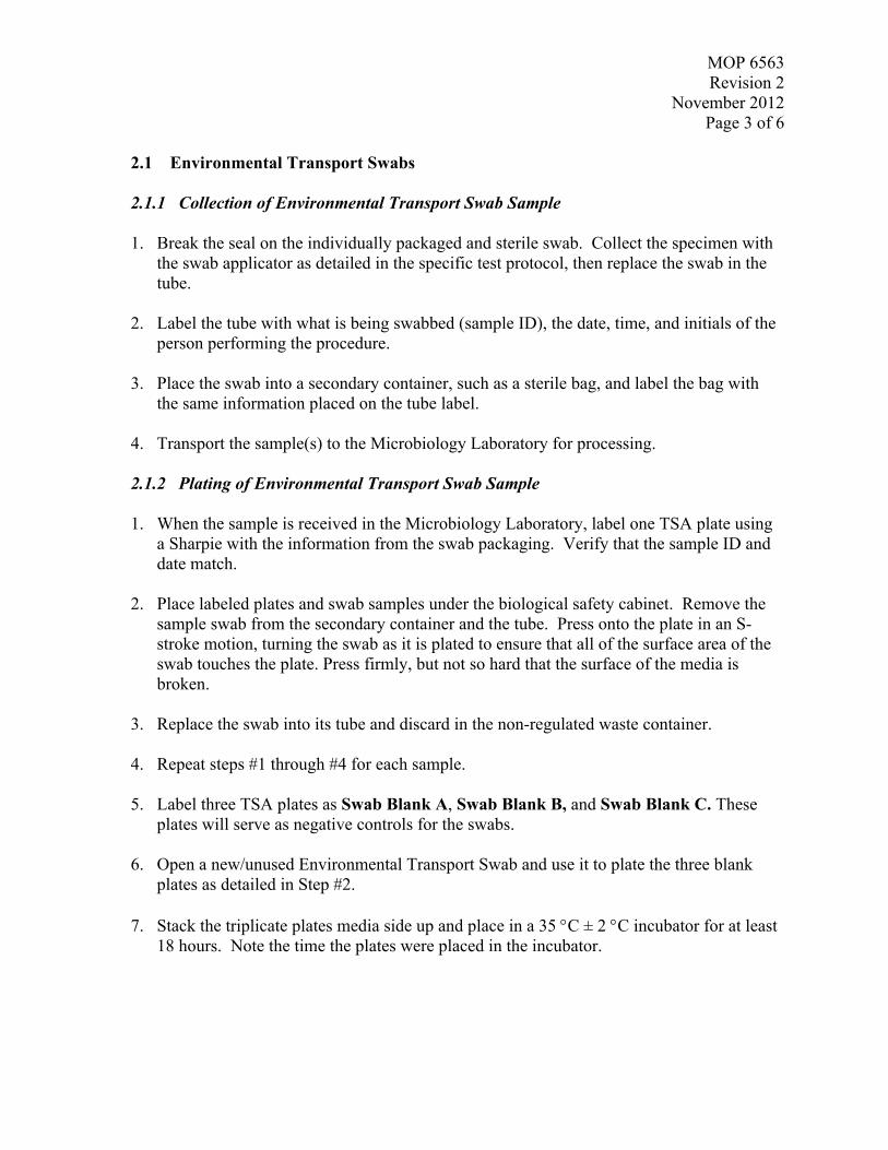
MOP 6563Revision 2
November 2012Page 3 of 6
2.1 Environmental Transport Swabs
2.1.1 Collection of Environmental Transport Swab Sample
1. Break the seal on the individually packaged and sterile swab. Collect the specimen withthe swab applicator as detailed in the specific test protocol, then replace the swab in thetube.
2. Label the tube with what is being swabbed (sample ID), the date, time, and initials of theperson performing the procedure.
3. Place the swab into a secondary container, such as a sterile bag, and label the bag withthe same information placed on the tube label.
4. Transport the sample(s) to the Microbiology Laboratory for processing.
2.1.2 Plating of Environmental Transport Swab Sample
1. When the sample is received in the Microbiology Laboratory, label one TSA plate usinga Sharpie with the information from the swab packaging. Verify that the sample ID anddate match.
2. Place labeled plates and swab samples under the biological safety cabinet. Remove thesample swab from the secondary container and the tube. Press onto the plate in an S-stroke motion, turning the swab as it is plated to ensure that all of the surface area of theswab touches the plate. Press firmly, but not so hard that the surface of the media isbroken.
3. Replace the swab into its tube and discard in the non-regulated waste container.
4. Repeat steps #1 through #4 for each sample.
5. Label three TSA plates as Swab Blank A, Swab Blank B, and Swab Blank C. Theseplates will serve as negative controls for the swabs.
6. Open a new/unused Environmental Transport Swab and use it to plate the three blankplates as detailed in Step #2.
7. Stack the triplicate plates media side up and place in a 35 C ± 2 C incubator for at least18 hours. Note the time the plates were placed in the incubator.

MOP 6563Revision 2
November 2012Page 4 of 6
2.2 In-house Sterilized Swabs
When In-house Sterilized Swabs are being used to collect samples, they need to be platedimmediately (unlike the Environmental Transport Swabs which are transported back to theMicrobiology Laboratory for plating). Therefore, prior to travelling to the sample site, collectthe following materials and supplies which will be needed:
One TSA media plate (in a media bag) per sample to be collected plus three additionalplates to be used as negative controls for swab blanks.
One In-house Sterilized Swab (in their autoclave pouches) per sample to be collected, oneswab for the control plates, plus a few extras.
Sharpie for labeling plates.
Use the following procedure to collect and plate samples.
1. Once at the sample collection site, take the TSA plates out of the media bag and label oneplate for each sample with what is being swabbed (sample ID), date, time, and initials ofthe person performing the procedure.
2. As carefully and as aseptically as possible, remove the swab from the autoclave pouch bythe stick end. Be sure and not touch the swab end to anything but the sample. If theswab’s sterility is compromised, dispose of the swab and use one of the extras.
3. Collect the specimen with the swab applicator as detailed in the specific test protocol.
4. Press onto the plate in an S-stroke motion, turning the swab as it is plated to ensure thatall of the surface area of the swab touches the plate. Press firmly, but not so hard that thesurface of the media is broken. Because these samples are being plated in the open airand not in a biological safety cabinet, be certain to limit the time that the lid is removedfrom the TSA plate.
5. Replace the swab into the autoclave pouch it came in and discard in the non-regulatedwaste container.
6. Repeat steps #1 through #6 for each sample.
7. Label three TSA plates as Swab Blank A, Swab Blank B, and Swab Blank C. Theseplates will serve as controls for both the swabs and the TSA.
8. Open another in-house sterilized swab from the autoclave pouch and use it to plate thethree blank plates as detailed in Step #2.

MOP 6563Revision 2
November 2012Page 5 of 6
9. Put the TSA plates back into the media bag and transport to the MicrobiologyLaboratory.
10. When received by the laboratory, the plates should be stacked media side up and placedin a 35 C ± 2 C incubator for at least 18 hours. Note the time the plates were placed inthe incubator.
3.0 ANALYZING THE SAMPLES
The Swab Results Template, which follows this section, is used to record the results of thesampling. Some quantities of samples may require more than one form. Make certain thatthe data is filled in completely on each page. The analyst will use the information on theTSA plates to fill in the following blanks at the top of the form:
Swab samples taken on: (date)
Swabbed by: (person)
Plating completed on: (date)
Plated by: (person)
The following procedure is used to analyze the samples and complete the remainder of theSwab Results Template form.
1. Fill in the final two sections at the top of the form: Plate results read on and Resultsread by.
2. Observe the agar surface on the plates and note the sample IDs on the first three lines inthe Sample column.
3. For each plate, check whether there was growth (G) or no growth (NG). Growth isindicative of an organism(s) being present, and should be described on the form. Be asdetailed as possible, noting colony morphology (size, shape, color and any otherdistinctive things that can be seen concerning the growth).
4. The Swab Results Template form serves as the sample report and should be provided tothe Project Manager.
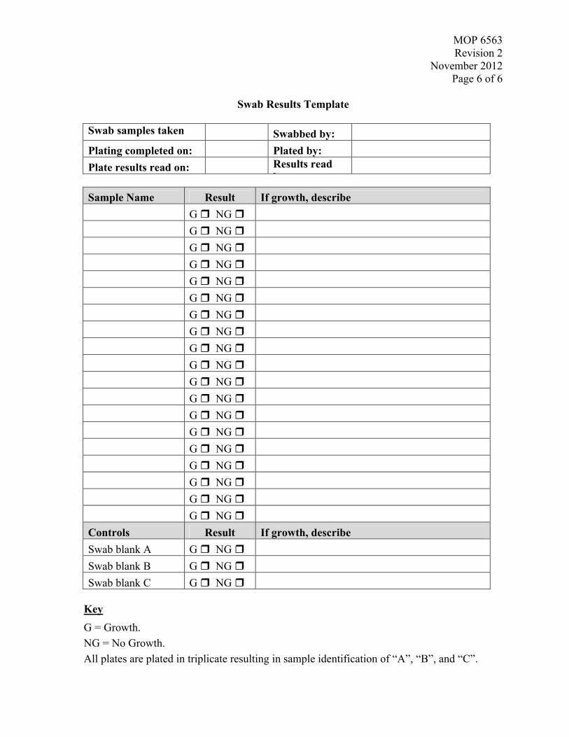
MOP 6563Revision 2
November 2012Page 6 of 6
Swab Results Template
Swab samples takenon:
Swabbed by:
Plating completed on: Plated by:
Plate results read on: Results readby:
Sample Name Result If growth, describe
G NG
G NG
G NG
G NG
G NG
G NG
G NG
G NG
G NG
G NG
G NG
G NG
G NG
G NG
G NG
G NG
G NG
G NG
G NG
Controls Result If growth, describe
Swab blank A G NG
Swab blank B G NG
Swab blank C G NG
Key
G = Growth.
NG = No Growth.
All plates are plated in triplicate resulting in sample identification of “A”, “B”, and “C”.

MOP 6565Revision 4
November 2012Page 1 of 4
Miscellaneous Operating Procedure (MOP) 6565:
Filtration and Plating of Bacteria from Liquid Extracts
Prepared by: __________________________________________ Date: 11/15/2012Nicole Griffin Gatchalian, ARCADIS Work Assignment Leader
Reviewed by: __________________________________________ Date: 11/15/2012Dahman Touati, ARCADIS Project Manager
Approved by: __________________________________________ Date: 11/15/2012Worth Calfee, EPA Work Assignment Manager
Prepared for
National Homeland Security Research CenterOffice of Research and Development
U.S. Environmental Protection AgencyResearch Triangle Park, NC 27711
Prepared by
ARCADIS U.S., Inc.4915 Prospectus Drive, Suite F
Durham, NC 27713

MOP 6565Revision 4
November 2012Page 2 of 4
MOP 6565
TITLE: FILTRATION AND PLATING OF BACTERIA FROM LIQUIDEXTRACTS
SCOPE: This MOP outlines the procedure for filtration and subsequent cultivationof bacterial spores from a liquid extract.
PRUPOSE: This method is deployed when results from spread-plate methods yieldless than 30 colony-forming units (CFU) per plate. This method allows alower limit of detection for bacterial recovery/survivorship assays. Thismethod can also be used to analyze liquid samples such as decon rinsates.
Materials:
Petri dishes with appropriate agar
0.2 µm pore-size disposable analytical filter units (2-3 per sample)
P1000 pipette and sterile tips
Sterile forceps
Pipettman and sterile serological pipettes
1.0 PROCEDURE
1. For each liquid sample to be analyzed, gather the required number of disposableanalytical filter units and Petri dishes containing the desired sterilized/QC’d media.
NOTE #1: For analysis of 5 to 30 ml extracts, 1 ml and remainder should befiltered; for 31 to 200 ml samples, 1 ml, 10 ml, and remainder shouldbe filtered; for samples over 200 ml, more filter samples may beneeded.
NOTE #2: For previously plated samples where 10 – 19 CFU were observed,replating using a 400 µl inoculum, and plates where 20 – 29 CFUwere observed, replating using a 200 µl inoculum can be executedrather than filter plating. For inoculua greater than 200 µl, a sterilespreader should be used rather than the bead method).

MOP 6565Revision 4
November 2012Page 3 of 4
2. Label plates.
3. Vortex liquid extract vigorously for 2 minutes, using 10 second bursts. (for largervolume samples, a vigorous mixing by shaking of the sample container can besubstituted for vortex mixing)
4. Using a P1000, sterile tip, and aseptic techniques, immediately following vortexing,pipette 1 ml of the extract into one of the filter units.
5. Apply vacuum to the filter unit, to pull the liquid through the filter and collect thespores on the surface of the filter.
6. Using a sterile serological pipette, rinse the filter unit by pipetting 10 ml of steriledeionized water along the inner sides of the unit while it is under vacuum.
7. Aseptically remove the filter from the filter apparatus using sterile forceps, and laythe filter onto the agar surface within the Petri dish (spore side up).
8. Vortex the liquid extract vigorously for 10 seconds.
9. Use the appropriate volume serological pipette to transfer the remaining aliquots intotheir respective filtration units (one at a time).
10. Repeat steps 5 through 7 taking time to vortex or mix the sample 10 secondsimmediately before removing an aliquot.
Important: Be sure to note and record the volume of the “remainder” sample.
11. Incubate all plates at the optimal growth temperature for the organism used for 16 –28 hours.
12. Enumerate and record the number of CFU on each plate.
2.0 DATA CALCULATIONS
Utilize the following equation to determine the total abundance of recovered spores:
filtered
Extract
V
VCFUN

MOP 6565Revision 4
November 2012Page 4 of 4
Where, N is the total number of spores recovered in the extract, CFU is the abundance ofcolonies on the agar plate, VExtract is the total volume of the extract (before any aliquotswere removed), VFiltered is the volume of the extract filtered.

MOP-6567Revision 1
November 2012Page 1 of 4
Miscellaneous Operating Procedure (MOP) 6567:
Recovery of Bacillus Spores from Wipe Samples
Prepared by: __________________________________________ Date: 11/15/2012
Nicole Griffin Gatchalian, ARCADIS Work Assignment Leader
Reviewed by: __________________________________________ Date: 11/15/2012
Dahman Touati, ARCADIS Project Manager
Approved by: __________________________________________ Date: 11/15/2012
Worth Calfee, EPA Work Assignment Manager
Prepared for
National Homeland Security Research Center
Office of Research and Development
U.S. Environmental Protection Agency
Research Triangle Park, NC 27711
Prepared by
ARCADIS U.S., Inc.
4915 Prospectus Drive, Suite F
Durham, NC 27713

MOP-6567Revision 1
November 2012Page 2 of 4
MOP 6567
TITLE: RECOVERY OF BACILLUS SPORES FROM WIPE SAMPLES
SCOPE: This MOP outlines the procedure for recovering Bacillus spores from wipesamples.
PURPOSE: To aseptically extract and quantify Bacillus spores from wipe samples in order todetermine viability and obtain quantifiable data.
Materials:
PPE (gloves, lab coat, safety goggles)
Biological Safety Cabinet (Class II)
pH-amended bleach
Deionized water
70% solution of denatured ethanol
Kimwipes
Disbatch® bleach wipes
Non-regulated waste container
50 mL sterile conical tubes containing 20 mL of sterile phosphate buffered saline with Tween20 solution (PBST) (MOP 6562)
Vortex mixer
Cart
Wire or foam rack for 50mL conical tubes
Tryptic soy agar plates
900 µL tubes of sterile PBST
Pipettor and pipette tips for dilutions
Incubator set to appropriate growth temperature for target organism (35°C or 55°C)
Light box for counting colonies
Lab notebook
QAPP for project that is utilizing the wipe samples
MOP-6567Revision 1
November 2012Page 3 of 4
1.0 PROCEDURE
1. Begin by donning PPE (gloves, lab coat, and protective eyewear).
2. Obtain wipe samples that may contain Bacillus spores. Wipe samples should be received asone wipe/sponge in a sterile 50 mL conical tube delivered in secondary containment. Makecertain that all of the samples are labeled. Review any chain of custody forms that mayaccompany the samples to ensure that all of the labels are consistent and that there is no notablevariation in the samples. If variation has occurred, make a note of it in the notebook.
3. Clean the workspace (biological safety cabinet) by wiping surfaces with pH-amended bleach,next with deionized water, and lastly with a 70-90 % solution of denatured ethanol. Wipe witha Kimwipe to remove any excess liquid. Make sure the workspace is clean and free of debris.Gather all necessary items to perform the task, place these items on a clean cart beside thebiological safety cabinet, within arm’s reach so that, once the procedure has begun, the taskmay be performed without interruptions.
4. Discard gloves and replace with fresh pair.
5. One at a time, under the biological safety cabinet, remove the sample tube containing the wipesample from the secondary containment bag in which it arrived. Using the Dispatch® bleachwipes, wipe each sample tube with one wipe, and then wipe it with a clean Kimwipe. Discardthe used bleach wipe and the used Kimwipe in the secondary containment bag and place themin the non-regulated waste container. Remove gloves and don a fresh pair of gloves. Repeatthis procedure for every sample. After each sample has been cleaned, place the tubescontaining the wipe samples in an appropriate sized wire or foam rack to hold the tubes in anupright, vertical position.
6. Leaving the tubes in the rack underneath the biological safety cabinet, aseptically add 20 mL ofPBST solution (this should be in a pre-measured, sterile conical tube, per MOP 6562) to eachsample tube containing a wipe, one a time. Remove the rack containing wipe samples fromhood when all samples have had the PBST added. Place the rack with the samples on the cart.
7. Using the procedure to clean the biological safety cabinet, as found in Step 3, clean thebiological safety cabinet again. Afterwards don a fresh pair of gloves.
8. Using a vortex mixer, agitate the wipe samples, four at a time, in a biological safety cabinet, forten second bursts for two minutes total. Make certain to clean the biological safety cabinetafter each set of four samples and change gloves between each set of samples.
NOTE: The reason that four samples are done at one time is to limit the time betweenagitation and plating. The samples need to be processed immediately after
MOP-6567Revision 1
November 2012Page 4 of 4
agitation, and agitation of more than four samples at a time leaves too muchtime between agitation and spread plating.
9. Using tryptic soy agar media plates that are appropriately labeled with the sample number,dilution set and date, complete dilution plating for the wipe samples immediately after the twominute agitation step is completed. The samples should also be agitated again for ten secondsdirectly prior to removing an aliquot from the sample tube. Each dilution tube should also beagitated for ten seconds prior to removal of aliquots. Dilutions should be completed using thetechniques and methodology as described in MOP 6535a, and the 900 µL tubes should bemade with sterile PBST to stay consistent with materials/solutions. Plating in this mannershould be repeated for all samples, with any changes in protocol noted in the lab notebook.
10. Once the dilution plating has been completed, the plates are to be placed in an incubator. Fornon-thermophilic Bacillus species, the plates should be placed at 35°C +/- 2° C for 12-24hours. For thermophilc Bacillus species, such as Geobacillus stearothermophilis, the platesshould be incubated at 55°C ±2 °C for 12-24 hours. The target Bacillus organism that will beused for the wipe samples will be specific to the project and noted in the QAPP.
11. After the plates have incubated for a sufficient amount of time (12-24 hours) and the growthfrom any Bacillus colonies are quantifiable, the colonies should be manually counted using thelight box and the data should be properly recorded as dictated per project by the QAPP. Allresults will be checked for quality assurance and all data will be reported to the properpersonnel as listed in the QAPP.

MOP 6570
Revision 3
March 2013
Page 1 of 4
Miscellaneous Operating Procedure (MOP) 6570:
Use of Steris Amsco Century SV 120 Scientific Prevacuum
Sterilizer
Prepared by: __________________________________________ Date: 3/21/2013
Nicole Griffin Gatchalian, ARCADIS Work Assignment Leader
Reviewed by: __________________________________________ Date: 3/21/2013
Dahman Touati, ARCADIS Project Manager
Approved by: __________________________________________ Date: 3/21/2013
Worth Calfee, EPA Work Assignment Manager
Prepared for
National Homeland Security Research Center
Office of Research and Development
U.S. Environmental Protection Agency
Research Triangle Park, NC 27711
Prepared by
ARCADIS U.S., Inc.
4915 Prospectus Drive, Suite F
Durham, NC 27713

MOP 6570
Revision 3
March 2013
Page 2 of 4
MOP 6570
TITLE: USE OF STERIS AMSCO CENTURY SV 120 SCIENTIFIC
PREVACUUM STERILIZER
SCOPE: Basic instructions for use of the large Steris autoclave.
PURPOSE: To outline proper procedural use of the autoclave, using preprogrammed
cycles, to effectively sterilize items, while complying with quality control
standards.
Materials:
Amsco Century SV 120 Scientific Prevacuum Sterilizer
Items to be sterilized (liquids, solids, waste, etc)
Pouches to contain materials during sterilization and maintain sterility until use
Aluminum foil
Autoclave indicator tape
Sterilization verification ampoules (such as Raven ProSpore Ampoules)
Thermally resistant gloves
De-Ionized (DI) water
1.0 PROCEDURE
1.1 Start Up
1. Turn on the autoclave. The power switch is located behind the door in the top right
corner. The digital touch screen on the front of the unit will power up and indicate
that a memory test is in progress.
2. After the memory test is complete, the device will request that it be flushed. This
should be conducted daily to minimize scaling inside the boiler. The flush valve is
located behind the door on the bottom, left of the device (yellow handle). Move the
valve to the open position and then press the “Start Timer” button on the touch
screen. The flush will run for 5 minutes and will alert at completion with a single
chime.
3. Once the flush is complete, close the flush valve and press the “Continue” button on
the touch screen. The screen should then return to its default menu which has 2
choices “Cycle Menu” and “Options”

MOP 6570
Revision 3
March 2013
Page 3 of 4
1.2 Basic Operation
1. Prepare any items that need to be sterilized. The items must be carefully wrapped or
sealed in sterilization pouches in order to maintain sterility when removed from the
autoclave. Examples of this include: wrapping any orifices with aluminum foil,
placing whole items in autoclave pouches, loosely applying a cap on a bottle (to allow
for the pressure changes inside).
2. Once prepared, each item should be outfitted with a sterility indicator such as a small
piece of autoclave indicator tape; or by utilizing an autoclave pouch with a built-in
sterility indicator strip. These indicators provide a visual verification that the
sterilizing temperature (121°C) was reached.
3. To add items to the autoclave, open the autoclave door by pressing down on the foot
pedal on the bottom right corner on the front of the device.
4. Place items that need to be sterilized into the autoclave, adding or moving racks to
accommodate the load. If liquids are being autoclaved, then they must have secondary
containment (usually a large plastic autoclave-safe tray) to contain any fluids in the
event of a leak, spill or boil-over. Add an indicator ampoule to the first autoclave
cycle of the day, regardless of the type of cycle.
5. Once the autoclave is loaded, press the foot pedal to close the autoclave door.
6. Once the door is sealed, a menu of the cycles can be seen by pressing the button on
the touch screen labeled “Cycle Menu”. Then choose the appropriate cycle by
touching the corresponding button. If the cycle chosen is the one desired for the
sterilization process, press the “Start Cycle” button. Otherwise, press “Back” to
return to the prior menu screen.
7. After the cycle has started, the type of cycle, the number of the cycle, the items
placed in the autoclave during the cycle, the time, whether or not an indicator
ampuole was included in the load, and the initials of the person starting the cycle
must be recorded in the autoclave log book, located in the drawer across form the unit
labeled “Autoclave Supplies.”
8. Quality control (QC) indicator ampoules, usually Raven ProSpore Ampoules with
Geobacillus stearothermophilus (at a concentration 10E6), are added to one cycle
each day to ensure that the autoclave is functioning properly. These ampoules are
used according to manufacturer’s instructions. These ampoules must be properly
labeled with the date in which they were autoclaved and the initials of the individual
that completed the cycle. At the beginning of each week, a positive control ampoule
must be processed, where the ampoule is placed directly into the 55°C water bath,
without being autoclaved. The positive control indicator ampoule should change
from purple to yellow in color, indicating growth. All test ampoules should be placed
in a water bath following the end of the cycle in which they are run. These ampoules
should not change color (from purple to yellow, but instead should remain a purple to

MOP 6570
Revision 3
March 2013
Page 4 of 4
purple-brown color). Ampoules should be checked at both 24 and 48 hour intervals
for growth and then finally recorded and disposed of after 48 hours. All QC
information concerning ampoules should be recorded in the autoclave notebook.
9. Upon completion of any cycle, the autoclave will alarm with a repeating beep for
approximately one minute. Any time after this alarm starts, it is safe to open the main
door (take caution because the steam escaping the chamber will be very hot when the
door is opened). The contents from the autoclave will be very hot; use protection to
remove items from the autoclave (thermally resistant gloves).
10. Place the contents of the autoclave in an appropriate place to cool, and close the
autoclave door using the foot pedal.
1.3 Cycles
1.3.1 Gravity Cycles
Gravity cycles are used to sterilize glassware and other utensils, which are not submerged
in nor contain any volume of liquid. These cycles are typically used for “dry” materials.
Currently there are two different gravity cycles programmed for daily operations: a 1-
hour cycle and a 30-minute cycle. The time that the chamber is held at the sterilization
temperature (121 °C) is the only difference between these two cycles. The different
sterilization times allow for the compensation of the various sizes of materials and more
resilient organisms. The 30-minute cycle is primarily used for a small quantity of
material. The 1 hour cycle is used for large loads or items containing a large amount of
contamination. The 1 hour cycle is recommended for inactivation of gram positive spore-
forming bacteria.
1.3.2 Liquid Cycles
Liquid cycles are used to sterilize a variety of liquids and solutions. The solutions are
typically mixed prior to sterilization. It is important to have secondary containment to
contain any fluids in the event of a leak, spill or boil-over. The 30-minute liquid cycle is
used to sterilize small volumes of liquid (usually less than 2L total). When attempting to
sterilize any volume larger than 2L, the 1-hour liquid cycle should be used to ensure
complete sterilization. The 1-hour liquid cycle is the preferential cycle used as the
destruction cycle for waste. In the event of materials (liquid or otherwise) being
contaminated/exposed microorganisms, the 1-hour liquid cycle will be used as the initial
means of decontamination. When completing a decontamination cycle, if there is no
liquid inside of a container, then deionized water must be added to the container or the
item must be submerge prior to the start of the cycle. Only items that are being
decontaminated can go in destruction cycles. Decontamination cycles cannot be mixed
with sterilization cycles.

MOP 6572Revision 2
November 2012Page 1 of 4
Miscellaneous Operating Procedure (MOP) 6572:
Recovery of Spores from Vacuum Sock Samples
Prepared by: __________________________________________ Date: 11/15/2012
Nicole Griffin Gatchalian, ARCADIS Work Assignment Leader
Reviewed by: __________________________________________ Date: 11/15/2012
Dahman Touati, ARCADIS Project Manager
Approved by: __________________________________________ Date: 11/15/2012
Worth Calfee, EPA Work Assignment Manager
Prepared for
National Homeland Security Research Center
Office of Research and Development
U.S. Environmental Protection Agency
Research Triangle Park, NC 27711
Prepared by
ARCADIS U.S., Inc.
4915 Prospectus Drive, Suite F
Durham, NC 27713

MOP 6572Revision 2
November 2012Page 2 of 4
MOP 6572
TITLE: RECOVERY OF SPORES FROM VACUUM SOCK SAMPLES
SCOPE: This MOP outlines the procedure for recovering spores from vacuum sock samples
PURPOSE: To aseptically extract and quantify spores from vacuum sock samples in order todetermine viability and obtain quantifiable data
MATERIALS
PPE (gloves, lab coat, safety goggles)
Biological Safety Cabinet (Class II)
pH-amended bleach
Deionized water
70% solution of denatured ethanol
Kimwipes
Disbatch® bleach wipes
Non-regulated waste container
3 oz. sterile specimen cup containing 20 mL of sterile phosphate buffered saline with Tween 20solution (PBST) (MOP 6562)
Sterile scissors
Vortex mixer
Cart
Tryptic soy agar plates
900 µL tubes of sterile PBST
Pipettor and pipette tips for dilutions
Incubator set to appropriate growth temperature for target organism (35 °C or 55 °C)
Light box for counting colonies
Lab notebook
QAPP for project that is utilizing the vacuum sock samples
MOP 6572Revision 2
November 2012Page 3 of 4
1.0 PROCEDURE
1. Begin by donning PPE (gloves, lab coat, and protective eyewear).
2. Obtain vacuum sock samples that may contain Bacillus spores. Vacuum sock samples shouldbe received as one vacuum sock in a sterile 5.5’ x 9 bag secondarily contained in a 10’ x 15’bag. Make certain that all of the samples are labeled. Review any chain of custody forms thatmay accompany the samples to ensure that all of the labels are consistent and that there is nonotable variation in the samples. If variation has occurred, make a note of it in the notebook.
3. Clean the workspace (biological safety cabinet) by wiping surfaces with pH-amended bleach,next with deionized water, and lastly with a 70-90 % solution of denatured ethanol. Wipe witha Kimwipe to remove any excess liquid. Make sure the workspace is clean and free of debris.Gather all necessary items to perform the task, place these items on a clean cart beside thebiological safety cabinet, within arm’s reach so that once the procedure has begun the task maybe performed without interruptions.
4. Discard gloves and replace with fresh pair.
5. Label a 3 oz. specimen cup to match the vacuum sock sample ID. The specimen cup contains20 mL of sterile PBST.
6. When extracting samples, handle one sample at a time from start to finish. Begin by removingthe inner bag from the outer bag. Discard the outer bag in the non-regulated waste container.Place the inner bag containing the vacuum sock under the hood. Loosen the cap on the 3 oz.specimen cup and open a pack of sterile scissors. Open the bag and remove the sock, carefulnot to touch the white part. Roll the non-sterile blue portion of the vacuum sock onto thesmaller cardboard ring. Dispose of the larger cardboard ring. Wet the vacuum sock by holdingthe upper blue portion of the vacuum sock (around the smaller cardboard ring) and dipping thelower 1-inch of the vacuum sock into the PBST. The vacuum sock will be allowed to absorbthe PBST for a few seconds. After wetting, the vacuum sock will be lifted up just above theopening of the specimen bottle, and a 1-inch vertical slit will be cut up the center from thebottom of the sock using sterile scissors (a new pair of scissors should be used for eachsample). The vacuum sock is then cut horizontally from side to side, about 1 inch from thebottom allowing the two pieces to fall into the specimen bottle. The vacuum sock should be cutonly where the sock has been wetted. Repeat the dip/cutting procedure until the entirecollection portion of the sock has been excised. The upper top blue portion of the vacuum sockwill then be discarded. Place used scissors in a discard pan. After samples are all extracted,scissors will be immediately autoclaved using a one hour gravity destruction cycle inpreparation for use with the next sample batch. Remove gloves and don a fresh pair of gloves.Repeat the extraction procedure for every sample, while maintaining aseptic technique.
7. After cutting all vacuum sock samples, all specimen cups (up to sixty samples at a time) shouldbe loaded into the sample cup holder of the orbital shaker-incubator. The samples are then

MOP 6572Revision 2
November 2012Page 4 of 4
agitated in the shaker incubator at 300 rpm for 30 minutes at room temperature. The samplesare then removed from the shaker incubator and brought to the Biological Safety Cabinet fordilution plating.
8. Using the procedure to clean the biological safety cabinet, as found in Step 3, clean thebiological safety cabinet again. Afterwards don a fresh pair of gloves.
9. Using tryptic soy agar media plates that are appropriately labeled with the sample number,dilution set and date, complete dilution plating for the vacuum sock samples immediately afterthe thirty minute agitation step is completed. The samples should also be agitated again for tenseconds directly prior to removing an aliquot from the specimen cup. Each specimen cupshould also be agitated for ten seconds prior to removal of aliquots. Dilution-plating should becarried out according to MOP 6535a. Dilution tubes used in MOP 6535a should containPBST to stay consistent with materials/solutions. Repeat procedure for all samples.
10. Once the dilution plating has been completed, the plates should be incubated. For non-thermophilic Bacillus species, the plates should be placed at 35°C ±2 °C for 18-24 hours. Forthermophilc Bacillus species such as Geobacillus stearothermophilis, the plates should beincubated at 55°C ±2 °C for 18-24 hours. The target Bacillus organism that will be used forthe vacuum sock samples will be specific to the project and noted in the QAPP.
11. After the plates have incubated for a sufficient amount of time (18-24 hours) and the growth isquantifiable, the colonies should be manually counted with the assistance of a light box. Thedata should be properly recorded as dictated per project by the QAPP. All results will bechecked for quality assurance and all data will be reported to the proper personnel as listed inthe QAPP.

MOP 6579
Revision 4
April 2013
Page 1 of 6
Miscellaneous Operating Procedure (MOP) 6579:
Recovery of Bacillus Spores from 37MM Filter Cassettes
Prepared by: __________________________________________ Date: 4/29/2013
Nicole Griffin Gatchalian, ARCADIS Work Assignment Leader
Reviewed by: __________________________________________ Date: 4/29/2013
Dahman Touati, ARCADIS Project Manager
Approved by: __________________________________________ Date: 4/29/2013
Worth Calfee, EPA Work Assignment Manager
Prepared for
National Homeland Security Research Center
Office of Research and Development
U.S. Environmental Protection Agency
Research Triangle Park, NC 27711
Prepared by
ARCADIS U.S., Inc.
4915 Prospectus Drive, Suite F
Durham, NC 27713

MOP 6579
Revision 4
April 2013
Page 2 of 6
MOP: 6579
Title: RECOVERY OF BACILLUS SPORES FROM 37MM FILTER CASSETTES
Objective: To aseptically extract and quantify recovery of Bacillus spores from 37mm filters used to
sample porous surfaces.
MATERIALS AND EQUIPMENT
Equipment:
Biological Safety Cabinet (BSC, Class II)
Sonicating cleaner (such as Branson 8510, 40KHz)
Incubator set to appropriate growth temperature for target organism (35 °C)
Light box for counting colonies
Vortex mixer
Cassette opening tool (SKC cat# 225-8372, www.SKCshopping.com)
Specimen cup rack (cat # 5534M1, http://www.medicus-health.com)
Materials:
Personal Protective Equipment (PPE) (gloves, lab coat, safety goggles)
1:10 Bleach, pH-amended to 7.0 with acetic acid
Dispatch bleach wipes
Disposable 500 ml beaker (such as Fisher Scientific cat #14-955-111D) (for discarding used tips
and beads/spreaders)
70% Solution of denatured ethanol
Kimwipes
Waste container
Sterile Phosphate Buffered Saline with Tween 20 solution (PBST) (MOP 6562)
Tryptic Soy Agar (TSA) plates
Sterile scissors or scalpels, preferably one for each sample
Sterile 1500 µL tubes filled with 900µL of sterile PBST
15 ml centrifuge tube containing 6 ml of sterile PBST (one for each sample)
Autoclaved 2 oz polypropylene jars with lids (cat # J037, cat # L208
www.containerandpackaging.com)

MOP 6579
Revision 4
April 2013
Page 3 of 6
Pipettor and pipette tips for dilutions (100 μl, 1000 μl, and 5000 μl.)
Pall Filter units 0.45 um MCE (VWR; catalog #28143-544)
Vacuum Pressure Gauge (McMaster; catalogue # 38545K16)
Disposable cell spreaders or glass beads for cell spreading
Disposable sterile thumb forceps
1.0 REMOVING FILTER AND DUST FROM CASSETTE
1. Begin by donning PPE (gloves, lab coat, and protective eyewear).
2. Each cassette should be received separately in a small sealable bag (primary containment), then
placed within secondary containment. Make certain that all of the samples are labeled. Review any
chain of custody forms that may accompany the samples to ensure that all of the labels are consistent
and that there is no notable variation in the samples. If discrepancies are found, make a note of each
one in the notebook.
3. Clean the workspace (BSC) by wiping surfaces with pH-amended bleach, next with deionized water,
and lastly with a 70-90 % solution of denatured ethanol. Wipe with a kimwipe to remove any excess
liquid. Make sure the workspace is clean and free of debris. Gather all necessary items to perform
the task.
4. Discard gloves and replace with fresh pair.
5. For each cassette sample, label one 2 oz polypropylene jar with the sample identifier.
6. One at a time, under the BSC, remove the conical tube and cassette from the primary containment
bag in which it arrived.
7. First wipe down the outside of the conical tube containing the vacuum tubing and adapter with a
disinfecting wipe, and place it into a rack. Then, aseptically add 5ml of premeasured PBST. Set the
rack to the side.
8. Remove the band from around the cassette using a sterile scalpel or sterile pair of scissors. Using
the Dispatch bleach wipes, wipe each cassette with a wipe, and then a clean kimwipe. Discard the
used bleach wipe and the used kimwipe in the secondary containment bag and place them in the non-
regulated waste container. Remove gloves and don a fresh pair of gloves before proceeding.
9. With the plug in place on the back side of the filter, remove the red plug from the front filter side of
the cassette, use a pipette and aseptically dispense about 1mL μl of PBST (taken from the tube
containing 6ml PBST) into the cassette. Roll the cassette around to allow the liquid to touch all
surfaces of the inside of the cassette. If there is a large quantity of dust inside, more PBST may be
needed to dampen the dust before opening the cassette.
10. Once a visual check has been completed to assure that the dust is dampened enough to prevent its
aerosolization, use the cassette tool to pry open the top section of the cassette by carefully rotating
the cassette while using the tool to pry the edges up. Be careful to hold the cassette right side up
while prying open, so as not to spill the liquid inside.

MOP 6579
Revision 4
April 2013
Page 4 of 6
11. When the cassette is open, use a pipette to aseptically rinse the inside walls of the cassette with 1 to
2 ml of PBST (additional aliquots from the same 5ml tube used previously), then remove the rinse
eluent (using the same transfer pipette) and place it in the 2 oz sterile cup labeled with the sample
identifier.
12. Use the cassette opening tool to then remove the middle section of the cassette in the same manner
as the top section, thereby allowing the filter to be removed. Using sterile forceps, aseptically
remove the filter, being careful not to pick up the support filter underneath, and place it in the 2 oz
polypropylene jar with the rinse eluent.
13. Use the remainder of the 6 ml PBST to rinse the walls of the middle and top sections of the cassette
while holding them over the open 2 oz cup. The entire 6 ml PBST, the filter and as much dust as can
be rinsed from the cassette should now be inside the 2 oz polypropylene jar.
14. Discard the cassette sections, support filter, cassette plugs, disposable pipettes and disposable thumb
forceps into the proper waste. Close the 2 oz jar tightly. Wipe outside of the jar with disinfecting
wipe and place in specimen cup rack or sample retention bin.
15. Wipe down the cassette opening tool thouroughly with a disinfecting wipe, and wipe down the
surface of the BSC as described in Step 3 above.
16. Change gloves, and repeat from Step 5 for each remaining sample set.
2.0 PROCESSING 37 MM FILTERS
1. Place the rack of conical tubes containing the 5mL of PBST with the vacuum tubing and adapters
into the sonicating bath with a weighted, waterproof, rectangular, flat surface on top of the tubes to
keep them from floating when submerged. Sonicate the conical tubes for 1 minute.
2. Remove the tubes from the sonicator and dry them with a kimwipe and wipe them with a
disinfecting wipe.
3. Vortex the conical tubes for 2 continuous minutes.
4. Aseptically transfer the 5mL of PBST from the conical tube samples to the 2oz specimen cup
containing the filter sample that corresponds with the conical tube sample. The labels on the conical
tube should match the label on the specimen cup.
5. After the aseptic transfer of extraction liquid from the conical tube to the specimen cup, using a 10
ml serological pipette, measure the amount of PBST extraction liquid that has been collected in the
2oz specimen cup. Record this number.
6. Place all 2 oz polypropylene cups containing the 37mm filters and 5 ml PBST in the specimen cup
rack, place a weighted waterproof, rectangular, flat surface on top of the jars to keep them from
floating when submerged in the sonicating bath.
7. Place the rack with the cups and the weighted surface into the bath so that they are submerged about
1 – 2 inches, leaving about 1 inch between the level of the bath water and the jar lid.

MOP 6579
Revision 4
April 2013
Page 5 of 6
NOTE: This may require one or two wire racks (test tube racks or additional cup holders) in the
bottom of the sonicating bath to achieve the correct level for the cups. Make sure the
sonicating bath is filled with water to the correct level as designated by the line on the
inside of the bath. A series of open racks is preferable to a basket for this purpose, as
the baskets provided by the bath manufacturers tend to have more solid walls with
small holes, which can restrict the sonic waves more than a wire rack.
8. When the correct level of submersion is achieved, turn on the sonicating bath (no heat) and sonicate
for 3 minutes, rotating the cup rack within the bath at the 1 min and 2 min mark (pick up, turn 90
degrees, re-submerge).
9. Remove the rack of cups from the sonicating bath and place on an absorbent pad. Remove each 2 oz
cup from the rack, wipe with a kimwipe to dry and place back inside the BSC.
3.0 FILTRATION AND PLATING OF BACTERIA FROM LIQUID EXTRACTS
1. Follow MOP 6535a for spread-plating samples in triplicate from the 2 oz cups.
2. Filtration – detailed in the steps below – is required only if extremely low recovery is expected.
a. Label three TSA plates with information specific to the sample and amount to be filtered.
b. Set up filter manifold with three filter unit cups.
c. Set the vacuum, with proper gauge, to no more than 10 inches Hg (4.9 psi).
d. Add 10 ml PBST to filter cup.
e. Add 1 ml sample eluent from sample cup to each filter cup on the manifold.
f. Open the vacuum valve and vacuum liquid through filter.
g. Rinse sides of filter cup with 10 ml of sterile PBST, vacuum through again.
h. Pop off sides of the filter cup by squeezing and lifting.
i. Use sterile forceps to lift filter and place it on the TSA, making sure good contact with the
agar surface is made and air pockets are minimized.
3. Repeat for subsequent sample jars, completing samples in batches of no more than 4. This will help
to avoid too much settling time between vortexing and plating.
4. Place all TSA plates in incubator set at 35 ºC and incubate 18 – 24 hrs before counting colonies.

MOP 6579
Revision 4
April 2013
Page 6 of 6
4.0 CALCULATIONS
For spread plates: total CFU recovered = (mean CFU on plate / 0.1ml volume plated) x (1/dilution
factor) x (5 ml total in jar)
For vacuum filter plates: total CFU recovered = (mean CFU on vacuum filter / volume filtered) x 5 ml
total in jar

MOP 6580Revision 2
February 2013Page 1 of 7
Miscellaneous Operating Procedure (MOP) 6580:
Recovery of Bacillus Spores from 3M Sponge-Stick™ Samples
Prepared by: __________________________________________ Date: 2/12/2013Nicole Griffin Gatchalian, ARCADIS Work Assignment Leader
Reviewed by: __________________________________________ Date: 2/12/2013Dahman Touati, ARCADIS Project Manager
Approved by: __________________________________________ Date: 2/12/2013Worth Calfee, EPA Work Assignment Manager
Prepared for
National Homeland Security Research CenterOffice of Research and Development
U.S. Environmental Protection AgencyResearch Triangle Park, NC 27711
Prepared by
ARCADIS U.S., Inc.4915 Prospectus Drive, Suite F
Durham, NC 27713

MOP 6580Revision 2
February 2013Page 2 of 7
MOP 6580
TITLE: RECOVERY OF BACILLUS SPORES FROM 3M SPONGE-STICK™SAMPLES
SCOPE: This MOP provides the procedure for recovering spores from 3M Sponge-Stick™ samples.
PURPOSE: To extract and quantify bacterial spores from 3M Sponge-Stick™ samplesusing a highly repeatable procedure.
MATERIALS
pH-amended bleach
70-90 % Solution of denatured ethanol
Deionized (DI) water
Kimwipes
3M Sponge-Stick™ samples (P/N SSL10NB), hereafter referred to as ‘sponge’
Seward Stomacher® bags (P/N BA6041/CLR)
Phosphate buffered saline with 0.05% TWEEN®20 (PBST) (SIGMA-ALDRICH, Co,
P/N P3563-10PAK)
MicroFunnel Disposable Filter Funnels, Pall Life Sciences (VWR P/N 55095-060) or
Nalgene Sterile Analytical Filter Unit (Fisher P/N 130-4020)
Disposable polystyrene serological pipettes (5mL and 10mL)
Tryptic Soy Agar (TSA) plates
Vortex mixer
Disposable sterile 10µl loops
Disposable sterile forceps
Disposable gloves
Cell spreaders or glass beads for spreading
Racks for 15 mL and 50 mL centrifuge tubes
Sterile, plastic, screw-cap 50 mL centrifuge tubes (e.g. Fisher Cat# 14-959-49A)

MOP 6580Revision 2
February 2013Page 3 of 7
Sterile, plastic, screw-cap 15 mL centrifuge tubes (e.g. Fisher Cat# 14-959-49D)
Pipette tips with aerosol filter for 1 mL and 200 μL
1.0 PREPARATION
Personnel must be familiar with all procedures prior to start.
1.1 Equipment Preparation
a) Begin by donning personal protective equipment (PPE) such as gloves, lab coat,and protective eyewear.
b) Clean the workspace (Biological Safety Cabinet; BSC) by wiping surfaces with pH-amended bleach, next with DI water, and lastly with a 70-90% solution of denaturedethanol. Allow any excess liquid to dry prior to beginning procedure. Make surethe workspace is clean and free of debris.
c) Assemble equipment in the BSC as needed: vortex mixer, filtration manifold,automatic pipettors, tips, racks, etc.
d) Assemble extra supplies, such as stomacher and reagents, near BSC.
1.2 Supply Preparation
a) Unpack shipping containers directly into a BSC.
b) If sponges are not in Stomacher® bags, label one Stomacher® bag for each spongeand place in a bag rack.
c) Label two sterile 50 mL centrifuge tubes for each sponge sample and place in tuberack.
d) For each sample, label TSA plates on the agar side of the plate with the samplenumber and the appropriate dilution factors, as per MOP 6535a (Serial Dilution:Spread Plate Procedure to Quantify Viable Bacterial Spores).
e) Label two additional plates for filter-plate analysis.

MOP 6580Revision 2
February 2013Page 4 of 7
2.0 PERFORM SPORE EXTRACTION, ELUTION, AND CULTURE PROCEDURE
2.1 Dislodge Spores from the Sample Sponges
a) Begin by donning a new pair of gloves. All subsequent procedures involvingmanipulation of sponges or spore suspensions must be carried out in a BSC.(Stomaching may occur outside the BSC when samples are double-contained insidethe indicated bags.)
b) If the sponges are not in Stomacher® bags, aseptically transfer each sponge to aStomacher® bag (labeled during step 1.2b) using sterile disposable forceps. Changeforceps between samples.
c) Aseptically add 90 mL of PBST to each bag that contains a sponge.
d) Stomach sponges in the PBST by completing the following:
Make certain the Stomacher® is set to MANUAL. Program the Stomacher®speed to 260 RPM and the timer to 1 minute.
Open the Stomacher® door by raising the lid fully upward and back. TheDOOR OPEN icon will be displayed.
Place the stomacher bag containing the sponge sample into a second stomacherbag to contain any leakage in the event the primary containment iscompromised. Place the combined bags such that 50 to 60 mm of the topportions protrude above the bag clamp, while making certain that the spongesample rests evenly between the homogenizer paddles.
Close the door to the Stomacher®. The DOOR OPEN icon will no longer beilluminated.
Stomach each sponge for 1 min by pressing the START button.
When the cycle ends, the Stomacher® will stop. If there is an emergent reasonto stop the stomacher during the 1 minute stomaching period, press the redbutton or the power button to do so prior to opening the Stomacher®. Stoppingthe Stomacher® by opening the door can damage the equipment.
Open the door of the Stomacher® and remove the bags containing the sponge.Grab the sponge from the outside of the bag with your hands. Move the sponge

MOP 6580Revision 2
February 2013Page 5 of 7
to the top of the bag while using your hands to squeeze excess liquid from thesponge.
Remove and discard the sponge using sterile forceps.
e) Repeat steps (b) through (d) for all samples.
f) Allow bags to sit for 10 min to allow elution suspension foam to settle beforebeginning the concentration step.
2.2 Remove Sponge Elution Suspension
a) Gently mix elution suspension up and down with a 50 mL pipette three times.
b) Split elution suspension volume equally.
Remove half of the suspension volume (~45 mL) with a sterile 50 mL pipetteand place it in a 50 mL screw capped centrifuge tube.
Place remaining suspension (~45 mL) into a second 50 mL tube.
c) Record suspension volumes on tubes and data sheet.
d) Repeat steps (a) through (c) for all samples.
2.3 Concentrate Sponge Elution Suspension (Optional)
a) Centrifuge 50 mL centrifuge tubes
Prior to daily use and before placing tubes into centrifuge, follow MOP 6558(Centrifuge Cleaning Procedure) for cleaning this equipment.
Add centrifuge tubes to rotor, evenly distributing weight.
Centrifuge tubes at 3500 x g for 15 min. Do not use the brake option on thecentrifuge to slow the rotor, as re-suspension of pellet may occur.
b) Carefully remove about 42mL of supernatant with a 50 mL pipette and discard toleave approximately 3 mL in each tube. The pellet may be easily disturbed and notvisible, so place pipette tip away from the tube bottom or side.

MOP 6580Revision 2
February 2013Page 6 of 7
c) Vortex and sonicate tubes as follows:
Set vortex mixer to level 10 and touch activation.
Turn on sonicator water bath.
Vortex tubes for 30 sec.
Transfer tubes to sonicator bath and sonicate for 30 sec.
Repeat vortex and sonication cycles two additional times.
d) Remove suspension from one tube with a sterile 5 mL pipette and place it in theother tube of the same sample. The combined result is the final sponge elutionsuspension.
e) Measure final volume of the final sponge elution suspension with 5 mL pipetteand record on tube and data sheet.
f) Repeat steps (e) through (i) for all samples.
2.4 Serially Dilute and Plate the Final Spore Elution Suspension
a) Use MOP 6535a to serially dilute and plate samples.
NOTE: If the samples are turbid, wide-orifice pipette tips may be used to preventclogging of pipette tips.
b) Place all plates in an incubator set at 35 ± 2 ºC for a maximum of 3 days. Platesshould be examined within 18-24 hours after start of incubation. Manuallyenumerate CFU of target organism and record data.
If the CFU is <300/plate, record actual number.
If the CFU is >300/plate, record as “too numerous to count” (TNTC)
2.5 Capture Spores on Filter Membranes and Culture on TSA
Choose one of the following to methods to filter the final spore elution suspension:
a) Complete filter plating using MOP 6565 (Filtration and Plating of Bacteria fromLiquid Extracts).

MOP 6580Revision 2
February 2013Page 7 of 7
b) Complete filter plating using the following method:
1) Place two 0.45 μm (pore-size) Microfunnels on a Pall vacuum manifold (Pall Cat# 15403).
2) Moisten Microfunnel membranes with 5 ml PBST, open vacuum, and vacuumthrough the filter. All filtering should be done with a vacuum pressure <20 cm Hg.
3) Make certain that the manifold vacuum valve is closed. Turn on the vacuum.
4) With the vacuum valve closed, place 10 mL of PBST into each filter cup.
5) Add 1.0 mL of the final sponge elution suspension to each filter cup.
6) Open valves and allow the suspension to flow through the filter, close the valve.
7) Rinse the walls of each Microfunnel cup with 10 mL of PBST. Reopen the valve toallow the suspension to flow through the filter.
8) Close the valve, turn off the vacuum pump. Slowly reopen the valve to equalize thepressures.
9) Squeeze the walls of the Microfunnel cup gently and separate the walls from thebase holding the filter. Remove each filter membrane with sterile disposableforceps and place grid-side up on a TSA plate. Make sure that the filter is in goodcontact with the surface of the agar. If an air pocket occurs under the filter, use thesterile forceps to lift the edge of the filter to release the air pocket for better contactwith the agar.
10) Record exact volume of the sponge elution suspension filtered on each plate. Itshould be 1 mL. (Greater sample volumes may be used to lower detection limits)
11) Repeat steps (1) through (8) for all each sample.
12) Incubate TSA plates with filter membranes at 35 ± 2 ºC for a maximum of 3 days.Plates should be examined within 18-24 hours after start of incubation. Manuallyenumerate CFU of target organism and record data.
If the CFU is <300/plate, record actual number.
If the CFU is >300/plate, record as “too numerous to count” (TNTC)
MOP 6582
Revision 2
April 2013
Page 1 of 10
Miscellaneous Operating Procedure (MOP) 6582:
Recovery of Bacillus Spores from Trace Evidence Filters
Prepared by: __________________________________________ Date: 4/29/2013
Nicole Griffin Gatchalian, ARCADIS Work Assignment Leader
Reviewed by: __________________________________________ Date: 4/29/2013
Dahman Touati, ARCADIS Project Manager
Approved by: __________________________________________ Date: 4/29/2013
Worth Calfee, EPA Work Assignment Manager
Prepared for
National Homeland Security Research Center
Office of Research and Development
U.S. Environmental Protection Agency
Research Triangle Park, NC 27711
Prepared by
ARCADIS U.S., Inc.
4915 Prospectus Drive, Suite F
Durham, NC 27713

MOP 6582
Revision 2
April 2013
Page 2 of 10
MOP: 6582
Title: RECOVERY OF BACILLUS SPORES FROM TRACE EVIDENCE FILTERS
Objective: To aseptically extract and quantify recovery of Bacillus spores from 3M Trace Evidence
filters (TEF) used to sample porous surfaces.
MATERIALS AND EQUIPMENT
Equipment:
Biological Safety Cabinet (BSC, Class II)
Incubator set to appropriate growth temperature for target organism (35 °C)
Light box for counting colonies
Vortex mixer
Stomacher (Seward Stomacher® 400 Circulator (Seward; catalog #0400/001/AJ)
Closure bags (catalog # BA6141/CLR)
Stomacher bag rack (Seward catalog # BA6090)
Specimen cup rack
50 mL Tube rack
Materials:
Personal Protective Equipment (PPE) (gloves, lab coat, safety goggles)
1:10 Bleach, pH-adjusted (pAB) to 7.0 with acetic acid
Dispatch bleach wipes
Disposable 500 mL beaker (such as Fisher Scientific cat #14-955-111D) (for discarding used tips
and beads/spreaders)
70% Solution of denatured ethanol
Kimwipes
Waste container
Sterile Phosphate Buffered Saline with Tween 20 solution (PBST) (MOP 6562)
Tryptic Soy Agar (TSA) plates
3M Forensic Vacuum Filter (Trace Evidence Filter) (Precision Data Products, Grand Rapids, MI
catalog #FF-1)
Stomacher bags, closure type (Seward catalog # BA6141/CLR)
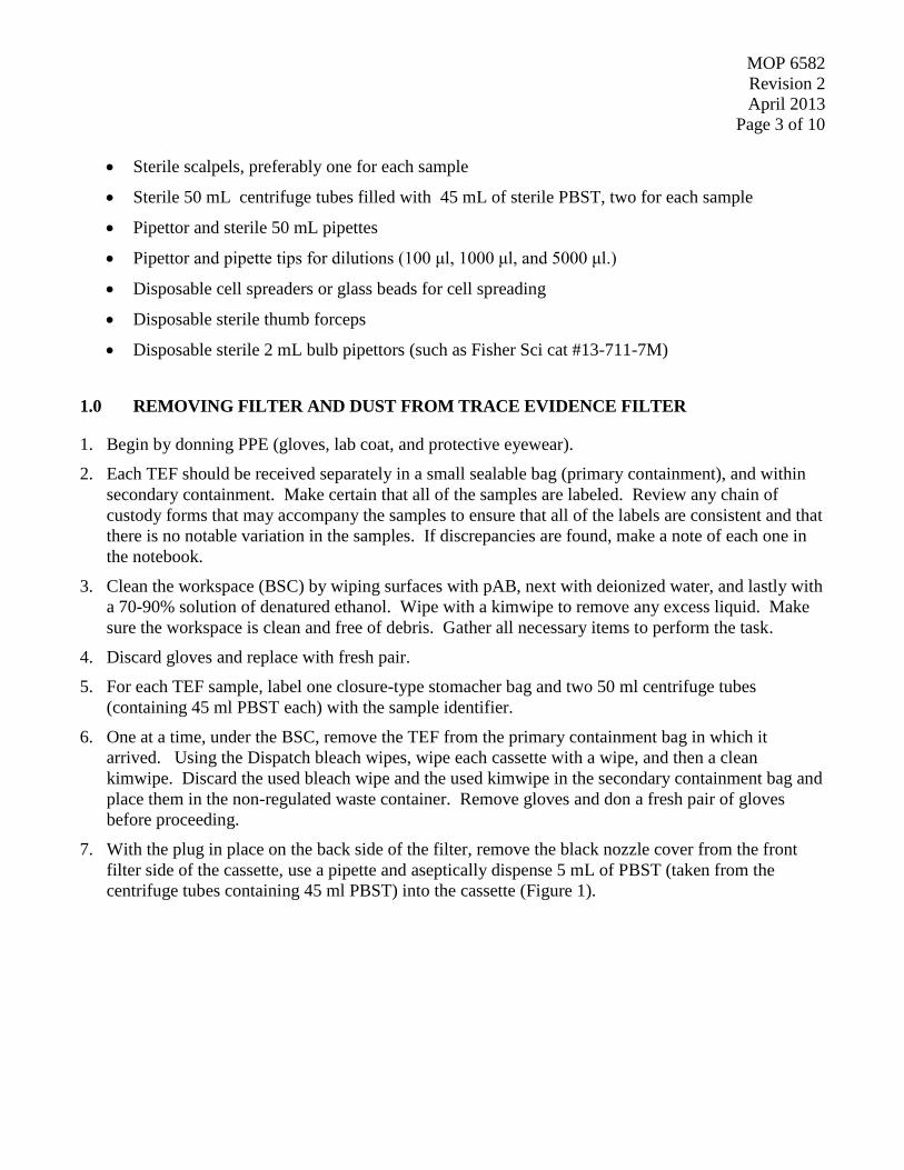
MOP 6582
Revision 2
April 2013
Page 3 of 10
Sterile scalpels, preferably one for each sample
Sterile 50 mL centrifuge tubes filled with 45 mL of sterile PBST, two for each sample
Pipettor and sterile 50 mL pipettes
Pipettor and pipette tips for dilutions (100 μl, 1000 μl, and 5000 μl.)
Disposable cell spreaders or glass beads for cell spreading
Disposable sterile thumb forceps
Disposable sterile 2 mL bulb pipettors (such as Fisher Sci cat #13-711-7M)
1.0 REMOVING FILTER AND DUST FROM TRACE EVIDENCE FILTER
1. Begin by donning PPE (gloves, lab coat, and protective eyewear).
2. Each TEF should be received separately in a small sealable bag (primary containment), and within
secondary containment. Make certain that all of the samples are labeled. Review any chain of
custody forms that may accompany the samples to ensure that all of the labels are consistent and that
there is no notable variation in the samples. If discrepancies are found, make a note of each one in
the notebook.
3. Clean the workspace (BSC) by wiping surfaces with pAB, next with deionized water, and lastly with
a 70-90% solution of denatured ethanol. Wipe with a kimwipe to remove any excess liquid. Make
sure the workspace is clean and free of debris. Gather all necessary items to perform the task.
4. Discard gloves and replace with fresh pair.
5. For each TEF sample, label one closure-type stomacher bag and two 50 ml centrifuge tubes
(containing 45 ml PBST each) with the sample identifier.
6. One at a time, under the BSC, remove the TEF from the primary containment bag in which it
arrived. Using the Dispatch bleach wipes, wipe each cassette with a wipe, and then a clean
kimwipe. Discard the used bleach wipe and the used kimwipe in the secondary containment bag and
place them in the non-regulated waste container. Remove gloves and don a fresh pair of gloves
before proceeding.
7. With the plug in place on the back side of the filter, remove the black nozzle cover from the front
filter side of the cassette, use a pipette and aseptically dispense 5 mL of PBST (taken from the
centrifuge tubes containing 45 ml PBST) into the cassette (Figure 1).

MOP 6582
Revision 2
April 2013
Page 4 of 10
Figure 1. Dispensing 5 mL PBST into TEF nozzle
8. Replace the black nozzle cover and roll the TEF around to allow the liquid to touch all surfaces of
the inside of the cassette. If there is a large quantity of dust inside, more PBST may be needed to
dampen the dust before opening the TEF. Be careful not to hold or squeeze the black nozzle cover,
as this may cause the seal to be disrupted, resulting in loss of PBST.
9. Once a visual check has been completed to assure that the dust is dampened enough to prevent its
aerosolization, use the sterile scalpel to cut through the red tape seal around the circumference of the
TEF.
10. Holding the TEF nozzle side up, open the plastic case of the filter. Turn the top of the filter case
upside down (nozzle side down with the black nozzle cover in place) and set aside for a moment,
inside the BSC on a rack (specimen cup rack will work) so that it will not be touching anything.
(Figure 2)

MOP 6582
Revision 2
April 2013
Page 5 of 10
Figure 2. Place the top half of the filter case onto a rack so that the filter can be removed from
the bottom half of the filter case.
11. Position the labeled stomacher bag in the bag rack so that the closure wires can be bent in a manner
so that the bag remains open while standing up in the rack (Figure 3).
Figure 3. Stomacher bag in bag holder with wires in open position, ready to accept filter and
liquid.

MOP 6582
Revision 2
April 2013
Page 6 of 10
12. Remove the moistened filter with sterile forceps and place in the stomacher bag (Figure 4).
Figure 4. Placing moistened filter into open stomacher bag.
13. Use a pipette to aseptically remove liquid that has collected under the filter during the moistening
step (Step 7 above). Place the liquid into the stomacher bag with the filter (Figure 5).
Figure 5. Transferring moistening liquid to stomacher bag.

MOP 6582
Revision 2
April 2013
Page 7 of 10
14. Use a disposable bulb pipette to aseptically rinse the inside walls of the bottom portion of the filter
case with 1 to 2 mL of PBST (additional aliquots from the same 45 mL tubes used previously), then
remove the rinse eluent (using the same transfer pipette) and place it into the stomacher bag along
with the filter (Figure 6).
Figure 6. Rinsing inside walls of filter case.
15. Repeat the rinsing step for the top portion of the filter case that was set aside (Step 10).
16. Pipette or pour the remainder of the 90 mL PBST (two tubes of 45 mL each) into the stomacher bag
that contains the filter and the rinsate of the filter case (Figure 7).
Figure 7. Pouring remainder of 90 mL PBST into stomacher bag.

MOP 6582
Revision 2
April 2013
Page 8 of 10
17. Discard the filter case, red plug nozzle cover, disposable pipettes and disposable thumb forceps into
the proper waste containers. DO NOT discard the 50 mL centrifuge tubes, as you will use these
again for centrifuging the eluent after processing in the stomacher.
18. Close stomacher bags by folding multiple times and folding the wire closures into the center of the
bag. Wipe the outside of the bag with a disinfecting wipe and place in a secondary stomacher bag
rack or sample retention bin.
19. Wipe down the surface of the BSC as described in Step 3 above.
20. Change gloves, and repeat from Step 5 for each remaining TEF sample.
2.0 PROCESSING TRACE EVIDENCE FILTERS
1. Set the stomacher to 1 min, 260 rpm (setting P3). Place one stomacher bag from Section 1.0, Step 18
(above) into the stomacher and run the cycle. Remove the stomacher bag and place back in the bag
rack.
2. Repeat for each sample.
3. Hold the samples at room temp for 10 min to allow the foam to settle in the stomacher bag (Figures
8 and 9).
Figure 8. Stomacher bag with sample; foam in stomacher bag immediately after 1 min
stomacher cycle.
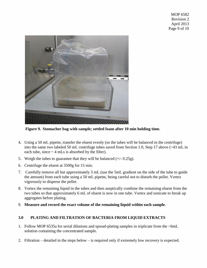
MOP 6582
Revision 2
April 2013
Page 9 of 10
Figure 9. Stomacher bag with sample; settled foam after 10 min holding time.
4. Using a 50 mL pipette, transfer the eluent evenly (so the tubes will be balanced in the centrifuge)
into the same two labeled 50 mL centrifuge tubes saved from Section 1.0, Step 17 above (~43 mL in
each tube, since ~ 4 mLs is absorbed by the filter).
5. Weigh the tubes to guarantee that they will be balanced (+/- 0.25g).
6. Centrifuge the eluent at 3500g for 15 min.
7. Carefully remove all but approximately 3 mL (use the 5mL gradient on the side of the tube to guide
the amount) from each tube using a 50 mL pipette, being careful not to disturb the pellet. Vortex
vigorously to disperse the pellet.
8. Vortex the remaining liquid in the tubes and then aseptically combine the remaining eluent from the
two tubes so that approximately 6 mL of eluent is now in one tube. Vortex and sonicate to break up
aggregates before plating.
9. Measure and record the exact volume of the remaining liquid within each sample.
3.0 PLATING AND FILTRATION OF BACTERIA FROM LIQUID EXTRACTS
1. Follow MOP 6535a for serial dilutions and spread-plating samples in triplicate from the ~6mL
solution containing the concentrated sample.
2. Filtration – detailed in the steps below – is required only if extremely low recovery is expected.

MOP 6582
Revision 2
April 2013
Page 10 of 10
a. Label three TSA plates with information specific to the sample and amount to be filtered.
b. Set up filter manifold with three filter unit cups.
c. Set the vacuum, with proper gauge, to no more than 10 inches Hg (4.9 psi).
d. Add 10 mL PBST to filter cup.
e. Add 1 mL sample eluent from sample cup to each filter cup on the manifold.
f. Open the vacuum valve and vacuum liquid through filter.
g. Rinse sides of filter cup with 10 mL of sterile PBST, vacuum through again.
h. Pop off sides of the filter cup by squeezing and lifting.
i. Use sterile forceps to lift filter and place it on the TSA, making sure good contact with the
agar surface is made and air pockets are minimized.
3. Repeat for subsequent sample tubes, completing samples in batches of no more than 4. This will help
to avoid too much settling time between vortexing and plating.
4. Place all TSA plates in incubator set at 35 ºC and incubate 18 – 24 hrs before counting colonies.
4.0 CALCULATIONS
For spread plates:
total CFU recovered = (mean CFU on plate / 0.1 mL volume plated) x (1/dilution factor) x (total
volume in centrifuge tube after decanting)
For vacuum filter plates:
total CFU recovered = (mean CFU on vacuum filter /volume filtered) x total volume in
centrifuge tube after decanting

MOP 6586Revision 2
February 2013Page 1 of 5
Miscellaneous Operating Procedure (MOP) 6586:
Recovery of Bacillus Spores from Quartz Filters
Prepared by: __________________________________________ Date: 2/12/2013Nicole Griffin Gatchalian, ARCADIS Work Assignment Leader
Reviewed by: __________________________________________ Date: 2/12/2013Dahman Touati, ARCADIS Project Manager
Approved by: __________________________________________ Date: 2/12/2013Worth Calfee, EPA Work Assignment Manager
Prepared for
National Homeland Security Research CenterOffice of Research and Development
U.S. Environmental Protection AgencyResearch Triangle Park, NC 27711
Prepared by
ARCADIS U.S., Inc.4915 Prospectus Drive, Suite F
Durham, NC 27713

MOP 6586Revision 2
February 2013Page 2 of 5
MOP: 6586
Title: RECOVERY OF BACILLUS SPORES FROM QUARTZ FILTERS
Objective: To aseptically extract and quantify recovery of Bacillus spores from quartz filters used tosample air.
MATERIALS AND EQUIPMENT
Equipment:
Biological Safety Cabinet (BSC, Class II)
Seward 400 Circulator Stomacher®
Incubator set to appropriate growth temperature for target organism (35 °C ± 2 ºC)
Light box for counting colonies
Vortex mixer
Stomacher bag rack
Serological pipette
Materials:
Personal Protective Equipment (PPE) (gloves, lab coat, safety goggles)
1:10 Bleach, pH-amended to 7.0 with acetic acid (pAB)
Dispatch bleach wipes
Disposable 500 ml beaker (such as Fisher Scientific, cat #14-955-111D) (for discarding used tipsand beads/spreaders)
70% Solution of denatured ethanol
Kimwipes
Waste container
Sterile Phosphate Buffered Saline with Tween 20 solution (PBST) (MOP 6562)
Tryptic Soy Agar (TSA) plates
Sterile 1500 µL tubes filled with 900µL of sterile PBST
120 mL specimen cup containing 100 mL of sterile PBST

MOP 6586Revision 2
February 2013Page 3 of 5
Pipettor and pipette tips for dilutions (100 μl, 1000 μl, and 5000 μl.)
Disposable cell spreaders or glass beads for cell spreading
100 mL serological pipette tips
Disposable sterile thumb forceps
10” x 15” Twirl’em bag (Fisher, cat # 01-002-53)
Quartz filter (Whatman, cat # 18209932)
Seward stomacher 400 bags (BA6141/CLR closure bags x 10)
1.0 PREPARATION
Personnel must be familiar with all procedures prior to start.
1.1 Equipment Preparation
a) Begin by donning personal protective equipment (PPE) such as gloves, lab coat, and protectiveeyewear.
b) Clean the workspace (Biological Safety Cabinet; BSC) by wiping surfaces with pH-amendedbleach (pAB), next with deionized (DI) water, and lastly with a 70-90% solution of denaturedethanol. Allow any excess liquid to dry prior to beginning procedure. Make sure theworkspace is clean and free of debris.
c) Assemble equipment in the BSC as needed: vortex mixer, filtration manifold, automaticpipettors, tips, racks, etc.
d) Assemble extra supplies, such as stomacher and reagents, near BSC.
e) Wipe down workspace once again with 70-90% solution of denatured ethanol.
1.2 Supply Preparation
a) Unpack shipping containers onto a cart near a BSC.
b) For each sample, label TSA plates on the agar side of the plate with the sample number and theappropriate dilution factors, as per MOP 6535a (Serial Dilution: Spread Plate Procedure toQuantify Viable Bacterial Spores).
MOP 6586Revision 2
February 2013Page 4 of 5
c) Pre-label sterile, empty 120 mL specimen cups to collect the extraction liquid from eachsample.
2.0 PERFORM SPORE EXTRACTION AND CULTURE PROCEDURE
2.1 Dislodge Spores from the Sample Filters
a) Begin by donning a new pair of gloves. All subsequent procedures involving manipulation ofthe filters or spore suspensions must be carried out in a BSC. (Stomaching may occur outsidethe BSC when samples are double-contained inside the indicated bags.)
b) Outside of the BSC, open the secondary (10” x 15”) containment bag containing the labeledstomacher bag containing the sample filter. Check to make sure the secondary bag and thestomacher bag have matching labels. Wipe down the stomacher bag with a dispatch wipe andplace in the stomacher rack located in the BSC. Discard the outer 10” x15” bag in the non-regulated waste container.
c) Aseptically add 100 mL of PBST to each labeled stomacher bag containing a filter. The 100mL of PBST should be pre-measured in a 120 mL specimen cup. Discard this specimen cupwhen empty.
d) Place the stomacher bag containing the quartz filter sample and PBST into a second stomacherbag to contain any leakage in the event the primary containment is compromised. Place thecombined bags such that 50 to 60 mm of the top portions protrude above the bag clamp, whilemaking certain that the quartz filter rests evenly between the homogenizer paddles.
e) Stomach filters in the PBST by completing the following:
1) Make certain the Stomacher® is set to MANUAL. Program the Stomacher® speed to 230RPM and the timer to 2 minutes.
2) Open the Stomacher® door by raising the lid fully upward and back. The DOOR OPENicon will be displayed.
3) Close the door to the Stomacher®. The DOOR OPEN icon will no longer be illuminated.
4) Stomach each filter for 2 min by pressing the START button.
5) When the cycle ends, the Stomacher® will stop.
Note: If there is an emergency, stop the stomacher by pressing the red button orthe power button prior to opening the Stomacher®. Stopping the Stomacher® byopening the door can damage the equipment.

MOP 6586Revision 2
February 2013Page 5 of 5
6) Open the door of the Stomacher® and remove the bags containing the filter. Remove thelabeled stomacher bag containing the filter sample and place it into the stomacher bag rack.The same secondary stomacher bag may be used for each sample provided there was noleak. If a leak was detected, leave the labeled stomacher bag in the secondary bag andplace both into the stomacher bag rack.
f) Repeat steps (b) through (d) for all samples.
g) Allow bags to sit for 10 min to allow the suspension foam to settle before beginning theextraction step.
2.2 Recovery of Suspension
a) Obtain a new, empty, pre-labeled 120 mL specimen cup with the same sample ID as that of thestomacher bag.
b) The suspension will be removed using a 100 mL pipette. Open the stomacher bag and removethe liquid by first tilting the bag to one side, moving the liquid away from the filter. Removeas much liquid as possible using the pipette.
c) When liquid can no longer be collected this way, simultaneously squeeze the filter and collectliberated liquid via pipette. Make attempts to locate pipette tip in a location within the bag thatreduces collection of filter debris.
NOTE: The filter particles can become lodged in the pipette tip. If this happens it may benecessary to eject some of the liquid to dislodge the particle.
d) After all the liquid has been removed from the bag, place it into the pre-labeled specimen cup.Make sure to note the volume collected on the specimen cup as well.
e) Discard the labeled stomacher bag with the filter into a non-regulated waste container.
f) Repeat steps (a) through (e) for each sample.
2.3 Serially Dilute and Plate the Final Spore Elution Suspension
a) Use MOP 6535a to serially dilute and plate samples.
NOTE: If the samples are turbid, wide-orifice pipette tips may be used to prevent clogging ofthe pipette tips.

MOP 6593 Revision 1 April 2013
Page 1 of 3
Miscellaneous Operating Procedure (MOP) 6593:
Recovery of Spores from HVAC Filters
Prepared by: __________________________________________ Date: 4/30/2013
Nicole Griffin Gatchalian, ARCADIS Work Assignment Leader
Reviewed by: __________________________________________ Date: 4/30/2013
Dahman Touati, ARCADIS Project Manager
Approved by: __________________________________________ Date: 4/30/2013
Worth Calfee, EPA Work Assignment Manager
Prepared for
National Homeland Security Research Center Office of Research and Development
U.S. Environmental Protection Agency Research Triangle Park, NC 27711
Prepared by
ARCADIS U.S., Inc. 4915 Prospectus Drive, Suite F
Durham, NC 27713

MOP 6593 Revision 1 April 2013
Page 2 of 3
MOP: 6593
Title: RECOVERY OF SPORES FROM HVAC FILTERS
Scope: This MOP outlines the procedure for recovering spores from HVAC filter sections
Purpose: To aseptically extract and quantify spores from sections of HVAC filters in order to determine viability and obtain quantifiable data
1.0 MATERIALS
PPE (gloves, lab coat, safety goggles)
Class II Biological Safety Cabinet (BSC)
pH-amended bleach
Deionized (DI) water
70% solution of denatured ethanol
Kimwipes
Dispatch bleach wipes
Non-regulated waste container
Bottles of sterile Phosphate Buffered Saline with Tween 20 solution (PBST) (MOP 6562)
Vortex mixer
Shaker table with clamps or brackets to hold Nalgene bottles
Cart
Trypticase soy agar (TSA) plates
900uL dilution tubes of sterile PBST
Pipettor and pipette tips for dilutions
Incubator set to appropriate growth temperature for target organism (35°C+/-2°C)
Light box for counting colonies
Lab notebook
Sterile graduated cylinder
Parafilm
2.0 PROCEDURE
1. Begin by donning PPE (gloves, lab coat, and protective eyewear).
2. Samples will be received as follows: Half portions of HVAC filters will be in 32oz white capped Nalgene jars (Fisher cat no. 2118-0032) and quarter portions of HVAC filters will be in 1L clear bottles (Fisher cat no. 02-893D). The samples should be secondarily contained by large sterile bags (10” x 15” sterile bags Fisher cat no. 01-002-53). Chain of custody forms that accompany the samples will need to be

MOP 6593 Revision 1 April 2013
Page 3 of 3
reviewed to ensure that all of the samples IDs are consistent and that there is no notable variation in the samples. If variation has occurred, make a note of it in the notebook.
3. Clean BSC workspace by wiping surfaces with pH-amended bleach, followed by DI water, and lastly
with a 70% solution of denatured ethanol. Wipe with a kimwipe to remove any excess liquid. Make sure the workspace is clean and free of debris. Gather all necessary items to perform the task, place these items on a clean cart beside the BSC, within arm’s reach so that once the procedure has begun the task may be performed without interruptions.
4. Discard gloves and replace with a fresh pair. 5. Place the samples one at a time, under the BSC. Samples should be handled in order of least
contaminated to most contaminated, with any negative controls or blank samples being handled first, test samples being handled next, and lastly the positive controls. Carefully unwrap the secondary containment bag from around the jar or bottle, discard in non-regulated waste container and then wipe down the jars or bottles with a dispatch wipe, followed by a Kimwipe. Change gloves after handling each sample.
6. Once all of the samples are under the BSC and disinfected, change gloves and place the sterile
graduated cylinder under the BSC, along with several bottles of sterile PBST. Again, in order from least contaminated to most contaminated, handle the samples individually, and carefully open the jars or bottles to aseptically add 700 mL of PBST to the sample. The PBST is first aseptically poured into the graduated cylinder and measured at 700 mL, and then it is aseptically poured from the graduated cylinder into the sample. Carefully transfer all liquid as to not spill any or disturb/touch the filter or its container in any way. Once the 700 mL of PBST has been added, carefully place the jar lid or bottle top back on the sample, and make certain it is tightly closed.
7. Again, wipe the outside of the samples with Dispatch wipes, followed by a Kimwipe to remove any
moisture. After all samples have 700 mL of sterile PBST added, wrap the sample lids/bottle tops with Parafilm to ensure a tight seal and to prevent sample leakage.
8. Place all sample jars or bottles into an orbital shaker table, using the specially designed platform
holders. Make certain all samples are secure, and shake at room temperature for 30 min at 300 rpm. 9. Immediately after the thirty minute agitation step is completed, remove the samples from the shaker and
place them, again from least contaminated to most contaminated, into the BSC for dilution plating. Don a fresh pair of gloves, remove and discard the Parafilm, and follow MOP 6535a to complete serial dilutions using TSA media plates that are appropriately labeled with the sample ID, dilution set, and date. Each sample should also be manually agitated for ten seconds prior to removal of aliquots. Dilution tubes used in MOP 6535a should contain PBST to stay consistent with materials/solutions.
10. Once the dilution plating has been completed, incubate the plates at 35°C +/- 2°C for 18-24 hours, and archive the samples in at refrigerator at 4°C+/-2°C.
11. Count the colonies with the assistance of a light box. Record data.
12. Colony forming units for each 6” x 12” half section or for each 6” x 6” quarter section will be determined
and the sum of the CFUs for the two or four sections making up one 12” x 12” sample will be determined. Data will be reported as total CFU for the 12” x 12” sample.

Offi ce of Research and Development (8101R)Washington, DC 20460
Offi cial BusinessPenalty for Private Use$300
PRESORTED STANDARDPOSTAGE & FEES PAID
EPAPERMIT NO. G-35