Bacics of RCC
57
BASICS BASICS OF OF R C C R C C
-
Upload
radhakrishnang -
Category
Documents
-
view
56 -
download
10
description
PPT file
Transcript of Bacics of RCC
BASICSBASICSOFOF
R C CR C C
We will discuss:-We will discuss:-
Few definitions,Few definitions, Basics of BM & SF diagrammeBasics of BM & SF diagramme Methods of designing,Methods of designing,
Why RCC ?Why RCC ?
Concrete WEEK in Tension.Concrete WEEK in Tension. Can’t take BENDING STRESSES,Can’t take BENDING STRESSES, Can’t take TORTIONAL STRESSES,Can’t take TORTIONAL STRESSES, Different shapes and design Different shapes and design
requirements,requirements, For higher loads,For higher loads,
Different type of loadingsDifferent type of loadings
AXIALAXIAL SHEARSHEAR BENDINGBENDING TORSIONTORSION
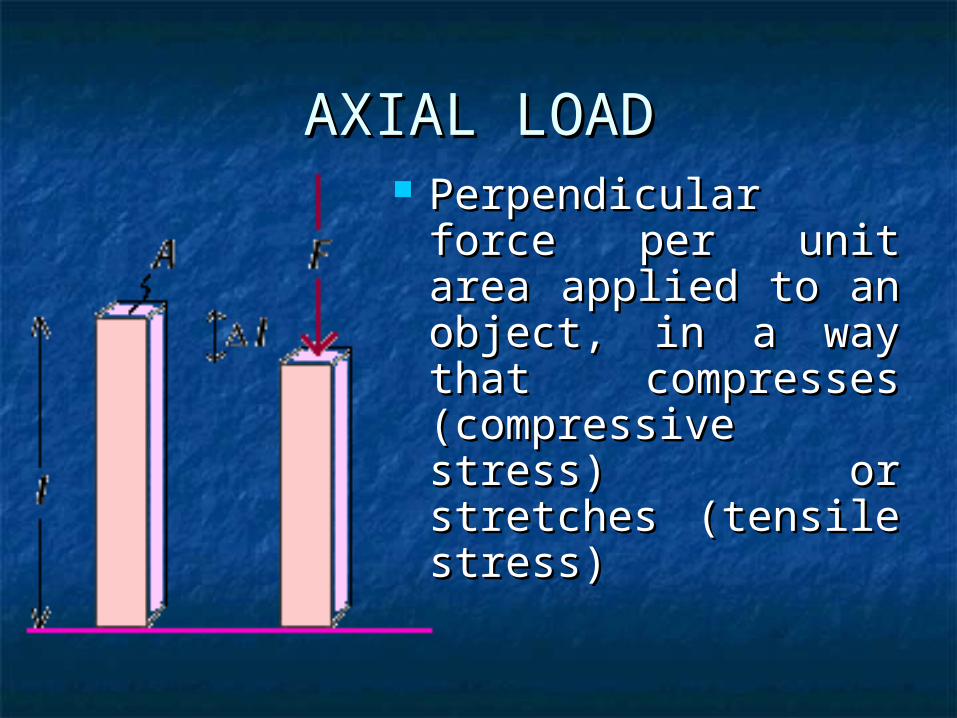
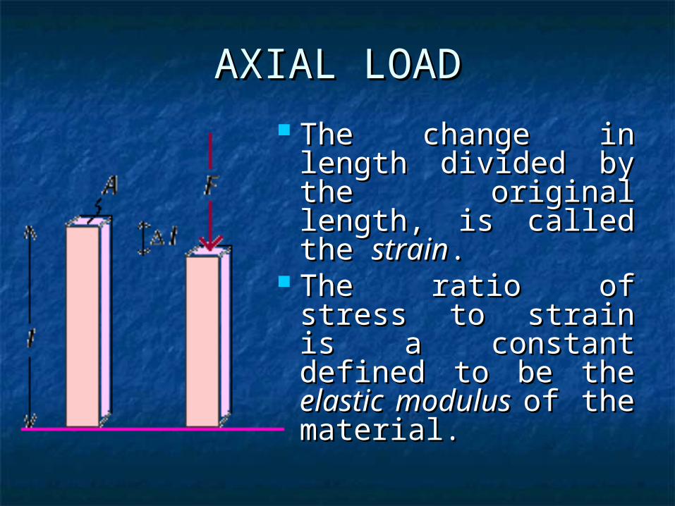
AXIAL LOADAXIAL LOAD Perpendicular force Perpendicular force
per unit area applied per unit area applied to an object, in a way to an object, in a way that compresses that compresses (compressive stress) (compressive stress) or stretches (tensile or stretches (tensile stress)stress)
AXIAL LOADAXIAL LOAD
The change in The change in length divided by length divided by the original length, the original length, is called the is called the strainstrain. .
The ratio of stress The ratio of stress to strain is a to strain is a constant defined to constant defined to be the be the elastic elastic modulus modulus of the of the material. material.

AXIAL LOADAXIAL LOAD
ELASTIC LIMIT: ELASTIC LIMIT: Limit upto which Limit upto which the strain varies the strain varies linearly with linearly with stress,stress,
Elastic modulus Elastic modulus
‘ ‘ E’ = Stress/ StrainE’ = Stress/ StrainStrainStrain
Str
ess
Str
ess
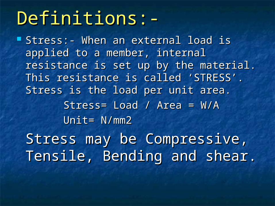
Definitions:-Definitions:- Stress:- When an external load is Stress:- When an external load is
applied to a member, internal applied to a member, internal resistance is set up by the material. resistance is set up by the material. This resistance is called ‘STRESS’. This resistance is called ‘STRESS’. Stress is the load per unit area.Stress is the load per unit area.
Stress= Load / Area = W/AStress= Load / Area = W/A
Unit= N/mm2Unit= N/mm2
Stress may be Compressive, Stress may be Compressive, Tensile, Bending and shear.Tensile, Bending and shear.
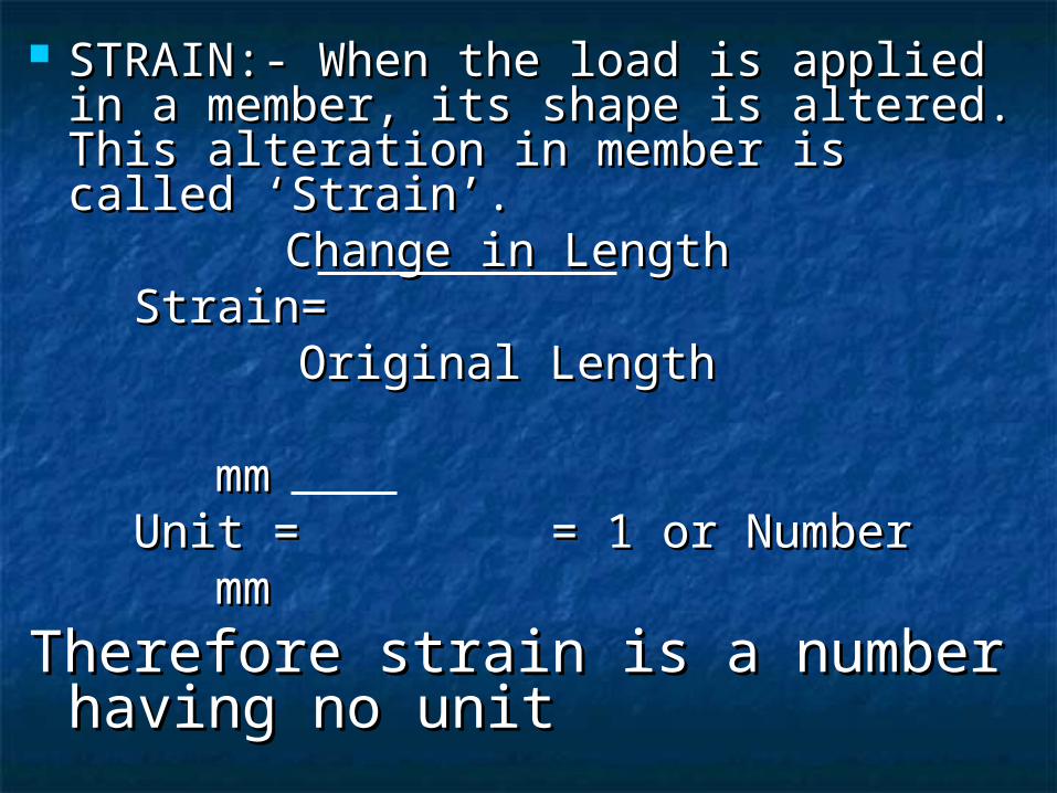
STRAIN:- When the load is applied in a STRAIN:- When the load is applied in a member, its shape is altered. This member, its shape is altered. This alteration in member is called ‘Strain’.alteration in member is called ‘Strain’.
Change in LengthChange in Length Strain= Strain=
Original Length Original Length
mmmmUnit = = 1 or NumberUnit = = 1 or Number
mm mm
Therefore strain is a number Therefore strain is a number having no unithaving no unit
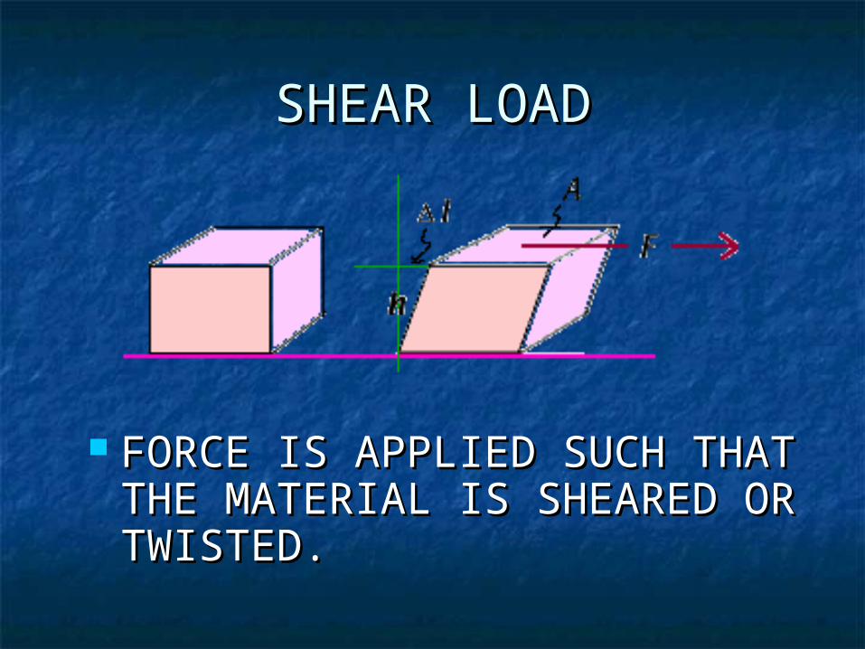
SHEAR LOADSHEAR LOAD
FORCE IS APPLIED SUCH THAT FORCE IS APPLIED SUCH THAT THE MATERIAL IS SHEARED OR THE MATERIAL IS SHEARED OR TWISTED. TWISTED.
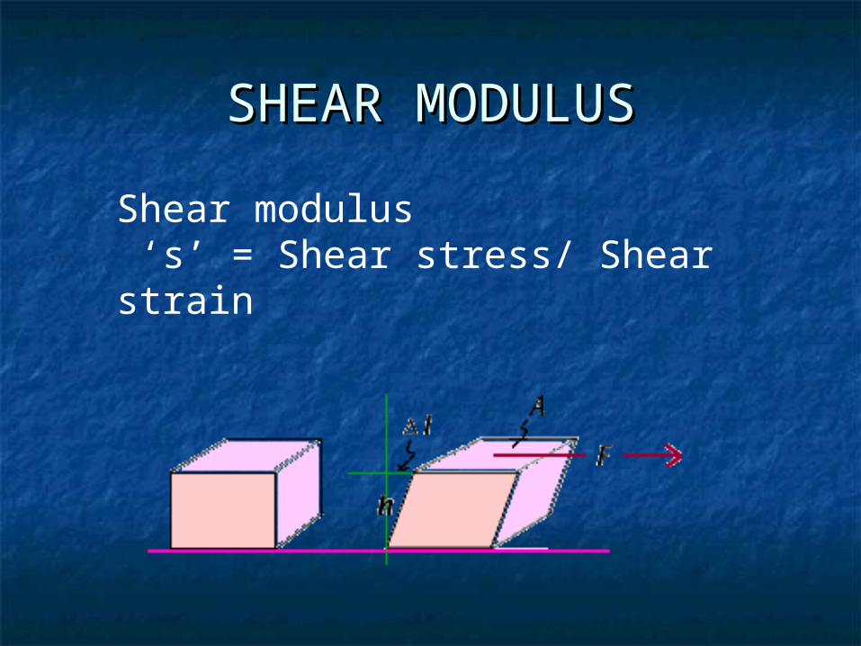
SHEAR MODULUSSHEAR MODULUS
Shear modulus ‘s’ = Shear stress/ Shear strain
SHEAR LOAD VS AXIAL SHEAR LOAD VS AXIAL LOADLOAD
Shear stressShear stress is a stress is a stress state where the stress is state where the stress is parallel or tangential to a parallel or tangential to a face of the material, as face of the material, as opposed to axial stress opposed to axial stress when the stress is when the stress is perpendicular to the face. perpendicular to the face.
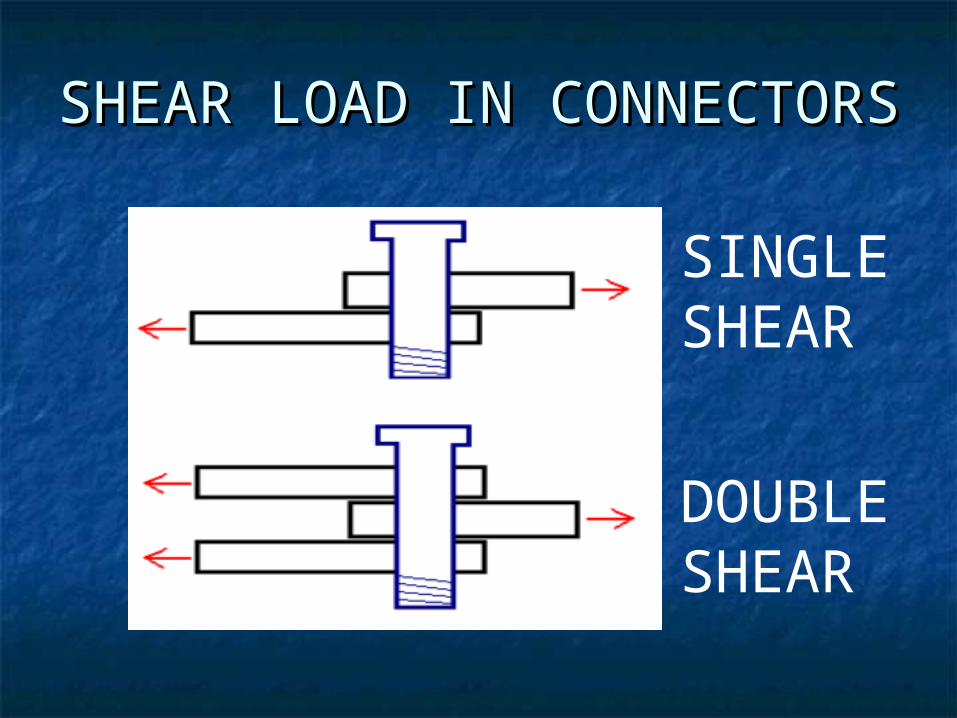
SHEAR LOAD IN SHEAR LOAD IN CONNECTORSCONNECTORS
SINGLE SHEAR
DOUBLE SHEAR
BENDING LOADBENDING LOAD
TRIES TO BEND THE MEMBER IN ONE TRIES TO BEND THE MEMBER IN ONE OF THE TWO AXIS OF THE SECTION OF THE TWO AXIS OF THE SECTION OF THE MEMBEROF THE MEMBER
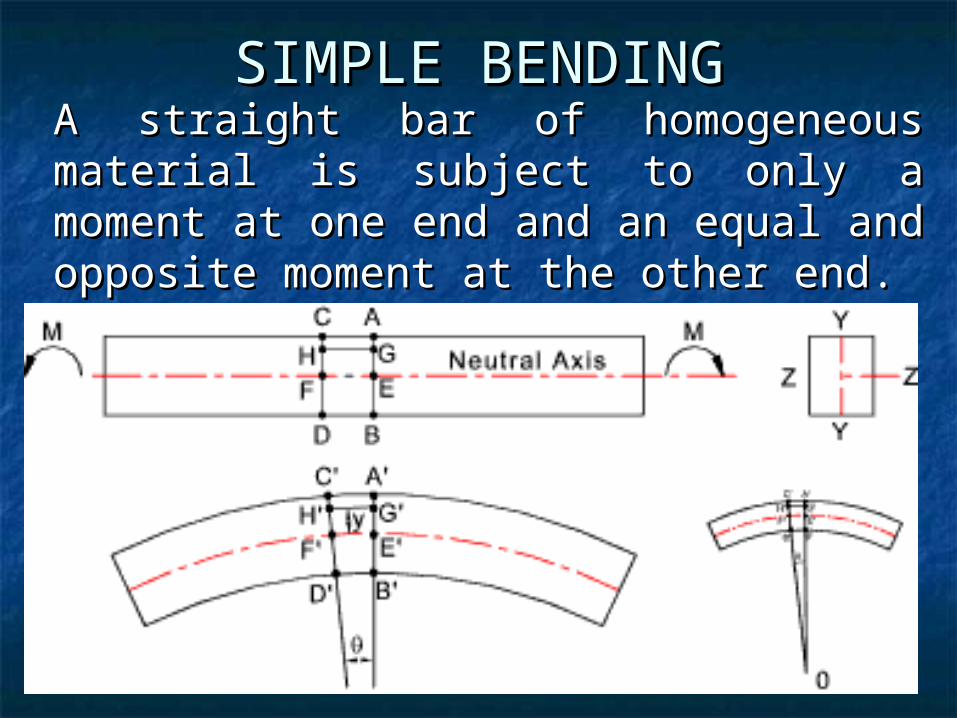
A straight bar of homogeneous material A straight bar of homogeneous material is subject to only a moment at one end is subject to only a moment at one end and an equal and opposite moment at and an equal and opposite moment at the other end.the other end.
SIMPLE BENDINGSIMPLE BENDING
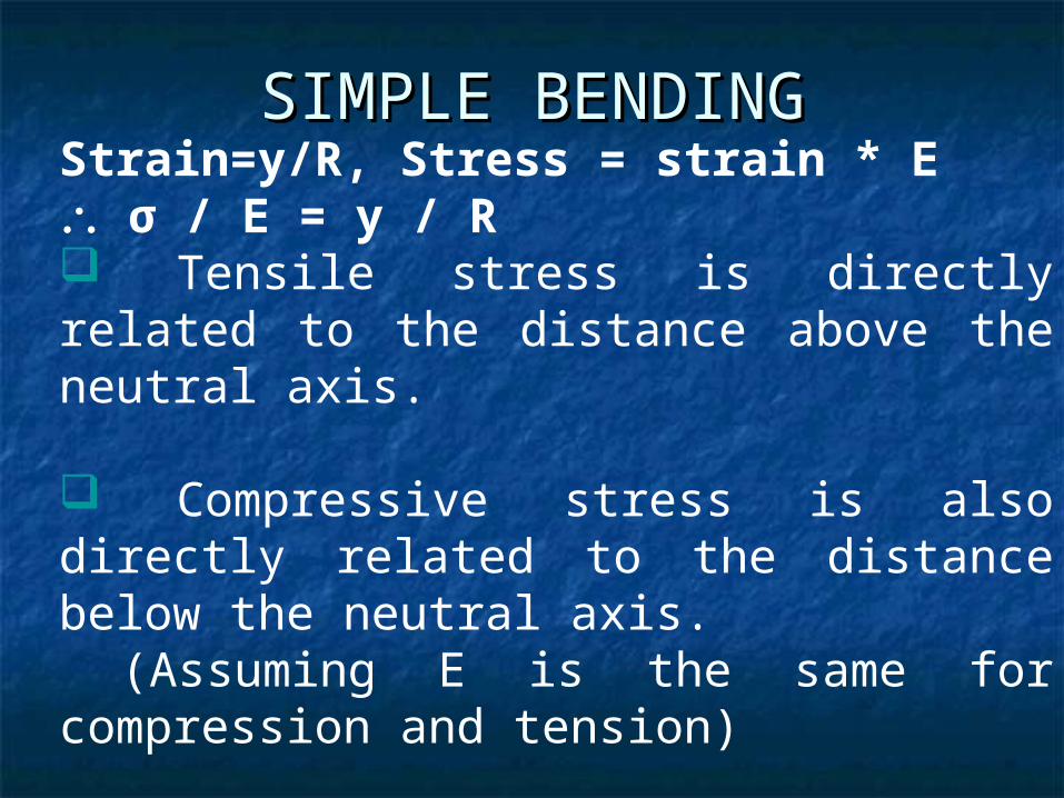
Strain=y/R, Stress = strain * E σ / E = y / R Tensile stress is directly related to the distance above the neutral axis. Compressive stress is also directly related to the distance below the neutral axis. (Assuming E is the same for compression and tension)
SIMPLE BENDINGSIMPLE BENDING
LOAD ON BEAMSLOAD ON BEAMS
Beam is analyzed for bending and Beam is analyzed for bending and shear stresses at various locations.shear stresses at various locations.
Sections to be provided as per Sections to be provided as per stressesstresses
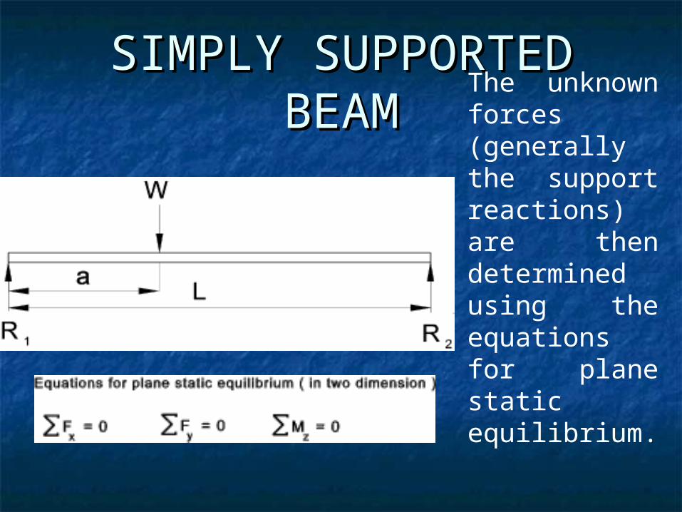
SIMPLY SUPPORTED SIMPLY SUPPORTED BEAMBEAM The unknown
forces (generally the support reactions) are then determined using the equations for plane static equilibrium.
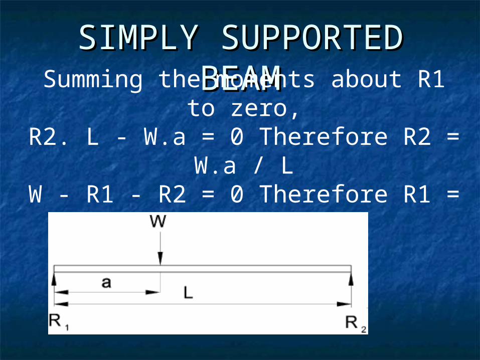
SIMPLY SUPPORTED SIMPLY SUPPORTED BEAMBEAMSumming the moments about R1 to
zero,R2. L - W.a = 0 Therefore R2 =
W.a / LW - R1 - R2 = 0 Therefore R1 = W -
R2
BENDING MOMENT AND BENDING MOMENT AND SHEAR FORCE DIAGRAMSHEAR FORCE DIAGRAM
The shear force diagram indicates The shear force diagram indicates the shear force withstood by the the shear force withstood by the beam section along the length of the beam section along the length of the beam.beam.
The bending moment diagram The bending moment diagram indicates the bending moment indicates the bending moment withstood by the beam section along withstood by the beam section along the length of the beam.the length of the beam.
BENDING MOMENT AND BENDING MOMENT AND SHEAR FORCE DIAGRAMSHEAR FORCE DIAGRAM
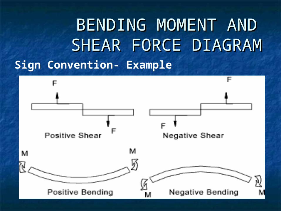
Sign Convention- Example
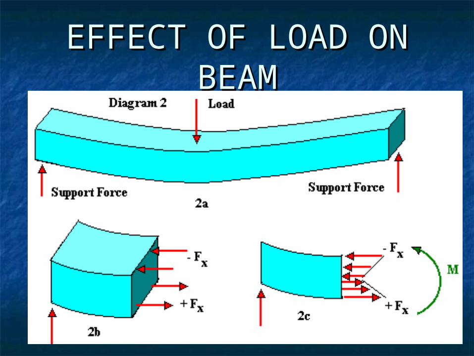
EFFECT OF LOAD ON EFFECT OF LOAD ON BEAMBEAM
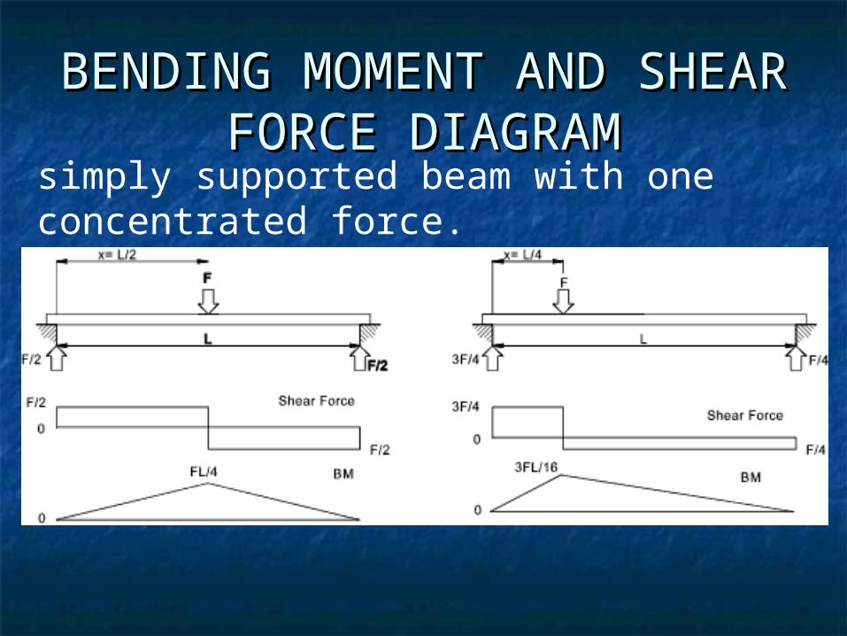
BENDING MOMENT AND BENDING MOMENT AND SHEAR FORCE DIAGRAMSHEAR FORCE DIAGRAM
simply supported beam with one concentrated force.
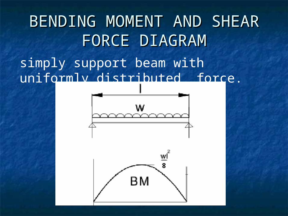
BENDING MOMENT AND SHEAR BENDING MOMENT AND SHEAR FORCE DIAGRAMFORCE DIAGRAM
simply support beam with uniformly distributed force.
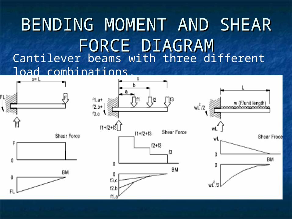
BENDING MOMENT AND BENDING MOMENT AND SHEAR FORCE DIAGRAMSHEAR FORCE DIAGRAM
Cantilever beams with three different load combinations.
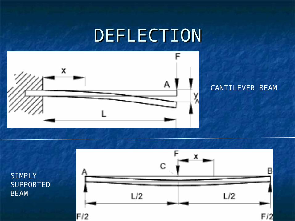
DEFLECTIONDEFLECTION
CANTILEVER BEAM
SIMPLY SUPPORTED BEAM
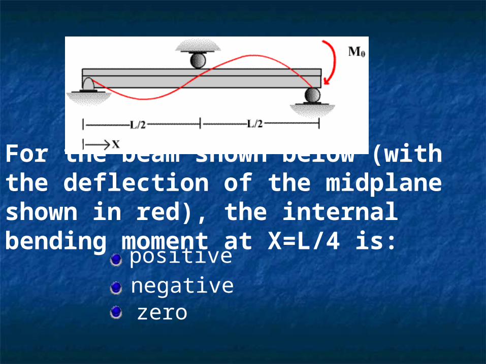
For the beam shown below (with the deflection of the midplane shown in red), the internal bending moment at X=L/4 is:
positive
negativezero
CONTINUOUS BEAMSCONTINUOUS BEAMS
The problem is indeterminateThe problem is indeterminate
Cannot be resolved by free body Cannot be resolved by free body diagramdiagram
Techniques to be used for finding Techniques to be used for finding out the forces and momentsout the forces and moments
CONTINUOUS BEAMSCONTINUOUS BEAMS
Techniques required Techniques required Moment distributionMoment distribution Slope deflectionSlope deflection Three moments theorem, etc..Three moments theorem, etc..
Superposition of loads possibleSuperposition of loads possible
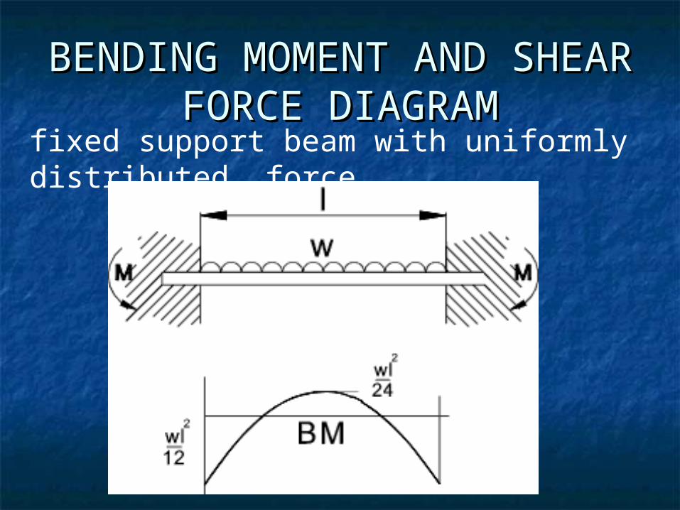
BENDING MOMENT AND BENDING MOMENT AND SHEAR FORCE DIAGRAMSHEAR FORCE DIAGRAM
fixed support beam with uniformly distributed force.
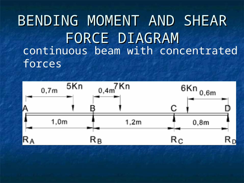
BENDING MOMENT AND BENDING MOMENT AND SHEAR FORCE DIAGRAMSHEAR FORCE DIAGRAM
continuous beam with concentrated forces
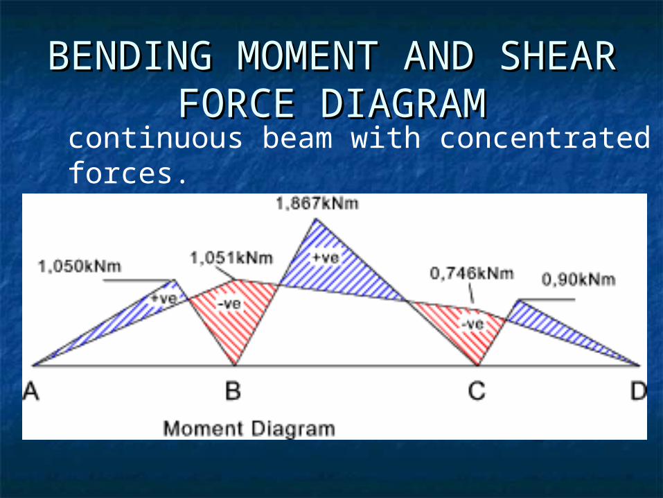
BENDING MOMENT AND BENDING MOMENT AND SHEAR FORCE DIAGRAMSHEAR FORCE DIAGRAM
continuous beam with concentrated forces.
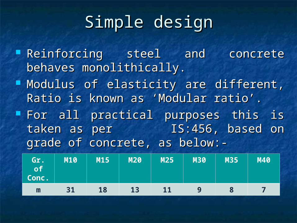
Simple designSimple design
Reinforcing steel and concrete behaves Reinforcing steel and concrete behaves monolithically.monolithically.
Modulus of elasticity are different, Ratio is Modulus of elasticity are different, Ratio is known as ‘Modular ratio’.known as ‘Modular ratio’.
For all practical purposes this is taken as For all practical purposes this is taken as per IS:456, based on grade of concrete, per IS:456, based on grade of concrete, as below:-as below:-
Gr. of Conc.
M10 M15 M20 M25 M30 M35 M40
m 31 18 13 11 9 8 7
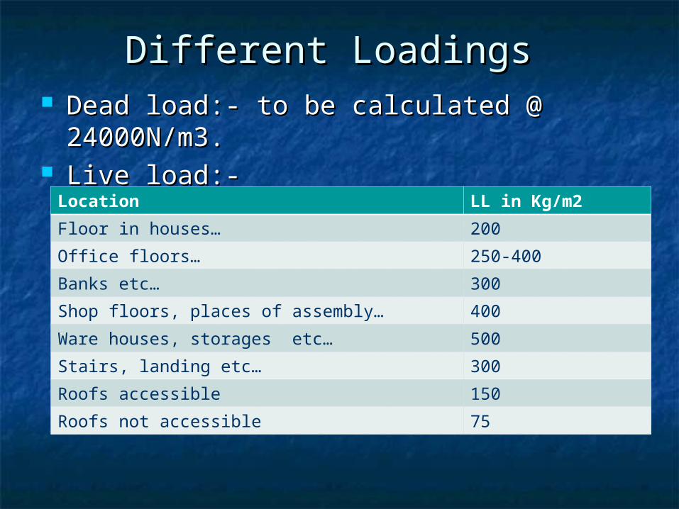
Different Loadings Different Loadings Dead load:- to be calculated @ Dead load:- to be calculated @
24000N/m3.24000N/m3. Live load:-Live load:-
Location LL in Kg/m2
Floor in houses… 200
Office floors… 250-400
Banks etc… 300
Shop floors, places of assembly… 400
Ware houses, storages etc… 500
Stairs, landing etc… 300
Roofs accessible 150
Roofs not accessible 75
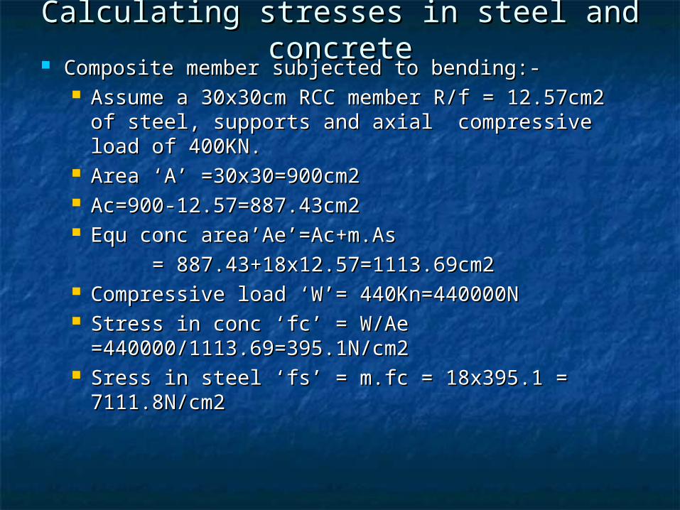
Calculating stresses in steel and Calculating stresses in steel and concreteconcrete
Composite member subjected to bending:-Composite member subjected to bending:- Assume a 30x30cm RCC member R/f = 12.57cm2 of Assume a 30x30cm RCC member R/f = 12.57cm2 of
steel, supports and axial compressive load of steel, supports and axial compressive load of 400KN.400KN.
Area ‘A’ =30x30=900cm2Area ‘A’ =30x30=900cm2 Ac=900-12.57=887.43cm2Ac=900-12.57=887.43cm2 Equ conc area’Ae’=Ac+m.As Equ conc area’Ae’=Ac+m.As
= 887.43+18x12.57=1113.69cm2= 887.43+18x12.57=1113.69cm2 Compressive load ‘W’= 440Kn=440000NCompressive load ‘W’= 440Kn=440000N Stress in conc ‘fc’ = W/Ae Stress in conc ‘fc’ = W/Ae
=440000/1113.69=395.1N/cm2 =440000/1113.69=395.1N/cm2 Sress in steel ‘fs’ = m.fc = 18x395.1 = Sress in steel ‘fs’ = m.fc = 18x395.1 =
7111.8N/cm27111.8N/cm2
Methods of Methods of designing,designing,
Working stress method,Working stress method, Ultimate load method,Ultimate load method, Limit state method.Limit state method.
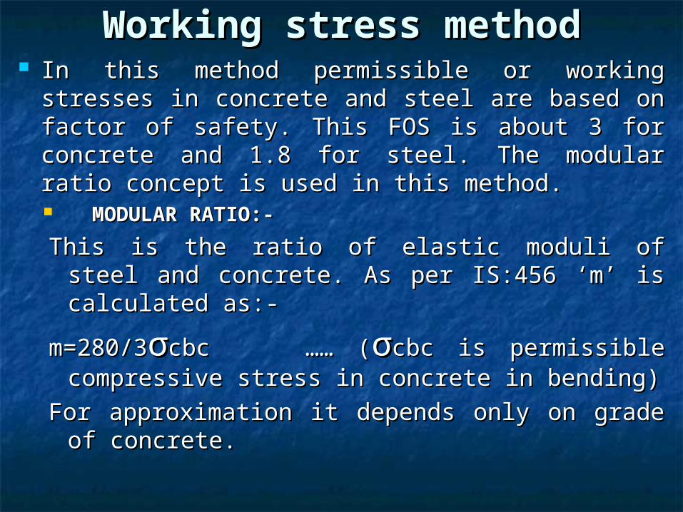
Working stress methodWorking stress method In this method permissible or working stresses In this method permissible or working stresses
in concrete and steel are based on factor of in concrete and steel are based on factor of safety. This FOS is about 3 for concrete and safety. This FOS is about 3 for concrete and 1.8 for steel. The modular ratio concept is 1.8 for steel. The modular ratio concept is used in this method.used in this method. MODULAR RATIO:-MODULAR RATIO:-
This is the ratio of elastic moduli of steel and This is the ratio of elastic moduli of steel and concrete. As per IS:456 ‘m’ is calculated concrete. As per IS:456 ‘m’ is calculated as:-as:-
m=280/3m=280/3σσcbc …… (cbc …… (σσcbc is permissible cbc is permissible compressive stress in concrete in bending)compressive stress in concrete in bending)
For approximation it depends only on grade For approximation it depends only on grade of concrete.of concrete.
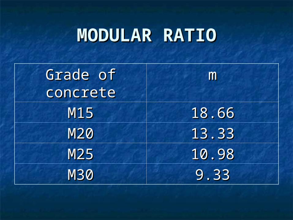
MODULAR RATIOMODULAR RATIO
Grade of Grade of concreteconcrete
mm
M15M15 18.6618.66M20M20 13.3313.33M25M25 10.9810.98M30M30 9.339.33
Fundamental assumption in Fundamental assumption in design:-design:-
Plane section will remain plain after Plane section will remain plain after bending also at any X-section.bending also at any X-section.
All tensile stresses taken by steel and All tensile stresses taken by steel and compressive stresses by concrete.compressive stresses by concrete.
Strain-stress relationship is straight Strain-stress relationship is straight line i.e. only elastic deformation is line i.e. only elastic deformation is there.there.
Modular ratio ‘m’ is as per IS:456.Modular ratio ‘m’ is as per IS:456. There is no slip in between steel and There is no slip in between steel and
concrete.concrete.
Ultimate load methodUltimate load method In this method inelastic or plastic In this method inelastic or plastic
behavior of concrete and steel are behavior of concrete and steel are considered. The loads are multiplied by considered. The loads are multiplied by a FOS also known as load factor, to a FOS also known as load factor, to arrive the ultimate loads. The ultimate arrive the ultimate loads. The ultimate stresses in concrete and steel are real stresses in concrete and steel are real known values. This method is used to known values. This method is used to check the structure for ultimate load check the structure for ultimate load carrying capacity after designing by carrying capacity after designing by ‘working stress method’ to give idea of ‘working stress method’ to give idea of real FOS of the structure. real FOS of the structure.
LIMIT STATE METHODLIMIT STATE METHOD Limit state method gives a new Limit state method gives a new
approach of statistical probability. A approach of statistical probability. A structure at failure may reach a limit structure at failure may reach a limit state, due to coincidental occurrence state, due to coincidental occurrence of both overload and excessive of both overload and excessive weakening of material at a critical weakening of material at a critical section.section.
Limit state may be defined as ‘The Limit state may be defined as ‘The acceptable limit for the safety and acceptable limit for the safety and serviceability of the structure before serviceability of the structure before failure occurs’.failure occurs’.
The two limit states are:-The two limit states are:-
1)1) Limit state of collapse:-Limit state of collapse:- Flexural (bending),Flexural (bending), Shear,Shear, Torsion.Torsion.
2)2) Limit state of serviceability:-Limit state of serviceability:- Deflection,Deflection, Cracking.Cracking.
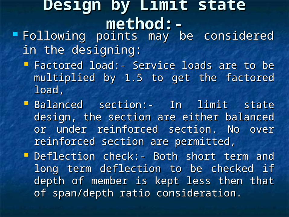
Design by Limit state Design by Limit state method:-method:-
Following points may be considered in Following points may be considered in the designing:the designing: Factored load:- Service loads are to be Factored load:- Service loads are to be
multiplied by 1.5 to get the factored load,multiplied by 1.5 to get the factored load, Balanced section:- In limit state design, Balanced section:- In limit state design,
the section are either balanced or under the section are either balanced or under reinforced section. No over reinforced reinforced section. No over reinforced section are permitted,section are permitted,
Deflection check:- Both short term and Deflection check:- Both short term and long term deflection to be checked if long term deflection to be checked if depth of member is kept less then that of depth of member is kept less then that of span/depth ratio consideration.span/depth ratio consideration.
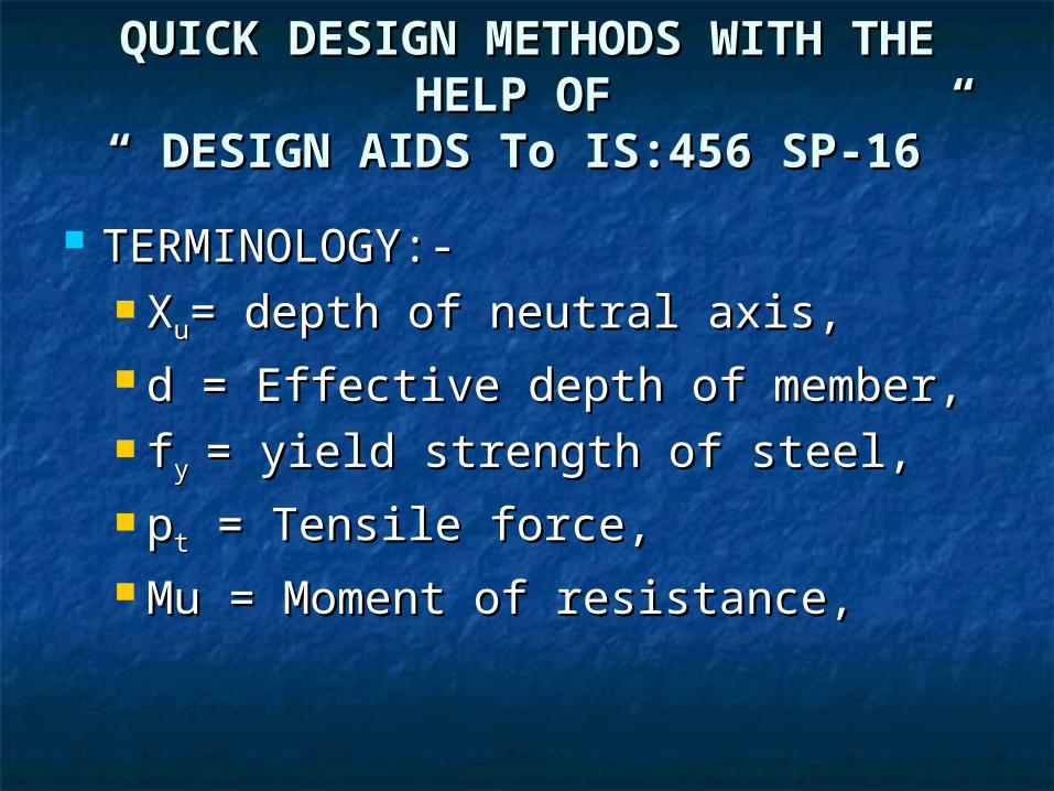
QUICK DESIGN METHODS WITH QUICK DESIGN METHODS WITH THE HELP OF THE HELP OF
“ DESIGN AIDS To IS:456 SP-16”“ DESIGN AIDS To IS:456 SP-16”
TERMINOLOGY:-TERMINOLOGY:- XXuu= depth of neutral axis,= depth of neutral axis, d = Effective depth of member,d = Effective depth of member, ffy y = yield strength of steel,= yield strength of steel, pptt = Tensile force, = Tensile force, Mu = Moment of resistance,Mu = Moment of resistance,
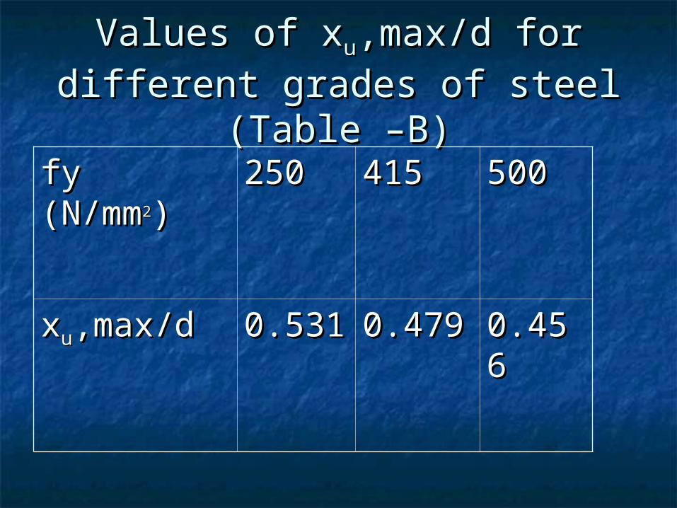
Values of xValues of xuu,max/d for different ,max/d for different grades of steel (Table –B)grades of steel (Table –B)
fy fy (N/mm(N/mm22))
250250 415415 500500
xxuu,max/d,max/d 0.5310.531 0.4790.479 0.4560.456
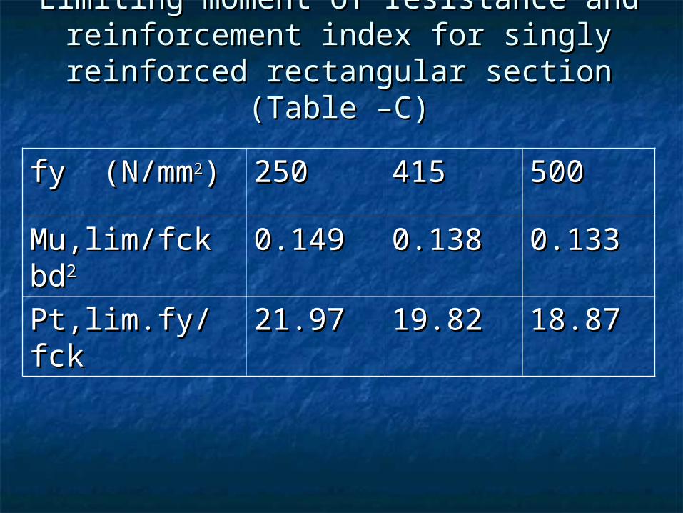
Limiting moment of resistance and Limiting moment of resistance and reinforcement index for singly reinforced reinforcement index for singly reinforced
rectangular section (Table –C)rectangular section (Table –C)
fy (N/mmfy (N/mm22)) 250250 415415 500500
Mu,lim/fck Mu,lim/fck bdbd22
0.1490.149 0.1380.138 0.1330.133
Pt,lim.fy/fckPt,lim.fy/fck 21.9721.97 19.8219.82 18.8718.87
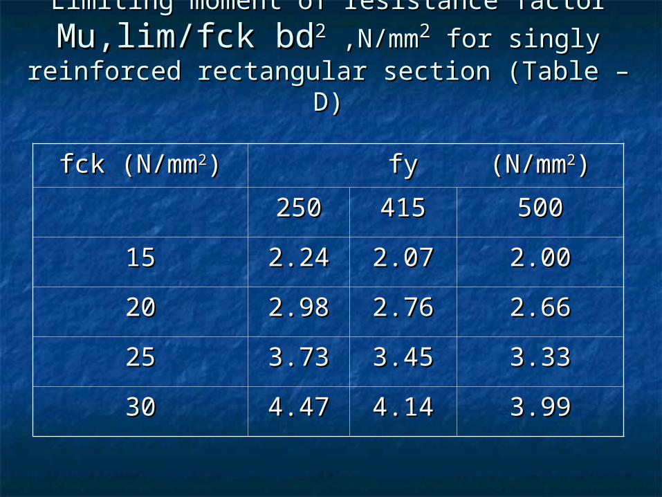
Limiting moment of resistance factor Limiting moment of resistance factor
Mu,lim/fck bdMu,lim/fck bd22 ,N/mm ,N/mm22 for singly reinforced for singly reinforced rectangular section (Table – D)rectangular section (Table – D)
fck (N/mmfck (N/mm22)) fyfy (N/mm(N/mm22))
250250 415415 500500
1515 2.242.24 2.072.07 2.002.00
2020 2.982.98 2.762.76 2.662.66
2525 3.733.73 3.453.45 3.333.33
3030 4.474.47 4.144.14 3.993.99
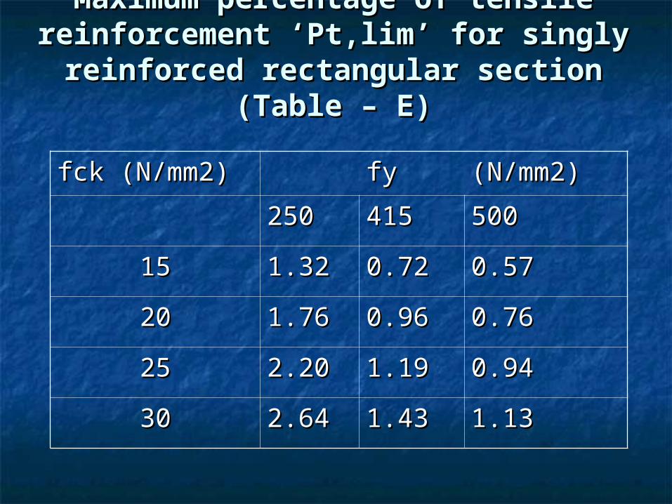
Maximum percentage of tensile Maximum percentage of tensile reinforcement ‘Pt,lim’ for singly reinforcement ‘Pt,lim’ for singly
reinforced rectangular section (Table reinforced rectangular section (Table – E)– E)
fck (N/mm2)fck (N/mm2) fyfy (N/mm2)(N/mm2)
250250 415415 500500
1515 1.321.32 0.720.72 0.570.57
2020 1.761.76 0.960.96 0.760.76
2525 2.202.20 1.191.19 0.940.94
3030 2.642.64 1.431.43 1.131.13
INTRODUCTION TO CHARTSINTRODUCTION TO CHARTS
For referring charts, we need values of For referring charts, we need values of moment per meter width i.e. (Mu/b) moment per meter width i.e. (Mu/b) and effective depth of the member ‘d’.and effective depth of the member ‘d’.
Charts are available for different grade Charts are available for different grade of concrete and steel to find of concrete and steel to find reinforcement percentage ‘100As/bd’ . reinforcement percentage ‘100As/bd’ .
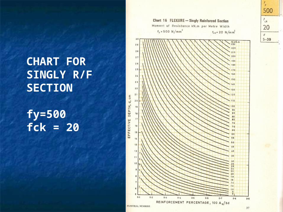
CHART FOR SINGLY R/F SECTION
fy=500fck = 20
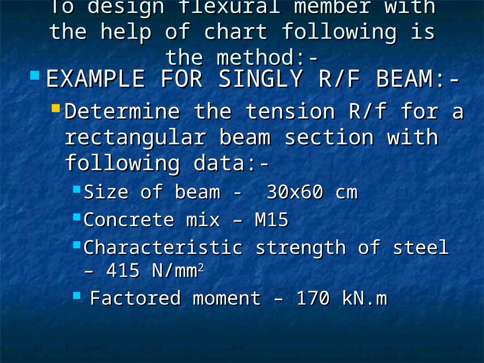
To design flexural member with the To design flexural member with the help of chart following is the method:-help of chart following is the method:-
EXAMPLE FOR SINGLY R/F BEAM:-EXAMPLE FOR SINGLY R/F BEAM:- Determine the tension R/f for a Determine the tension R/f for a
rectangular beam section with rectangular beam section with following data:-following data:-Size of beam - 30x60 cmSize of beam - 30x60 cmConcrete mix – M15Concrete mix – M15Characteristic strength of steel – 415 Characteristic strength of steel – 415 N/mmN/mm22
Factored moment – 170 kN.mFactored moment – 170 kN.m
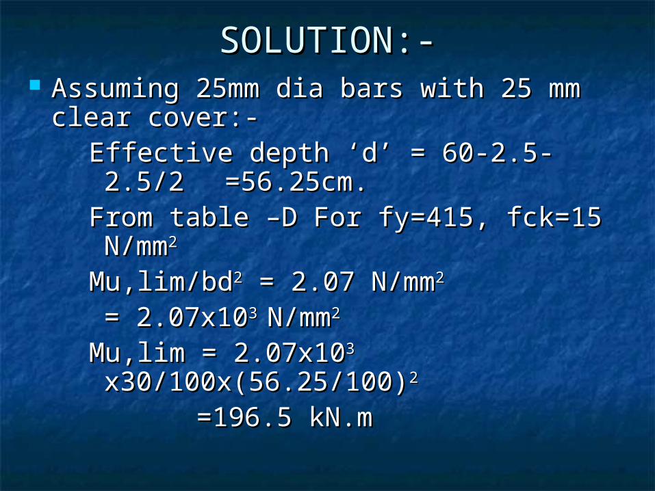
SOLUTION:-SOLUTION:- Assuming 25mm dia bars with 25 mm Assuming 25mm dia bars with 25 mm
clear cover:-clear cover:-Effective depth ‘d’ = 60-2.5-2.5/2 Effective depth ‘d’ = 60-2.5-2.5/2
=56.25cm.=56.25cm.From table –D For fy=415, fck=15 From table –D For fy=415, fck=15 N/mmN/mm22
Mu,lim/bdMu,lim/bd22 = 2.07 N/mm = 2.07 N/mm22 = 2.07x10= 2.07x10³ 3 N/mmN/mm22
Mu,lim = 2.07x10Mu,lim = 2.07x10³ 3
x30/100x(56.25/100)x30/100x(56.25/100)2 2 =196.5 kN.m=196.5 kN.m
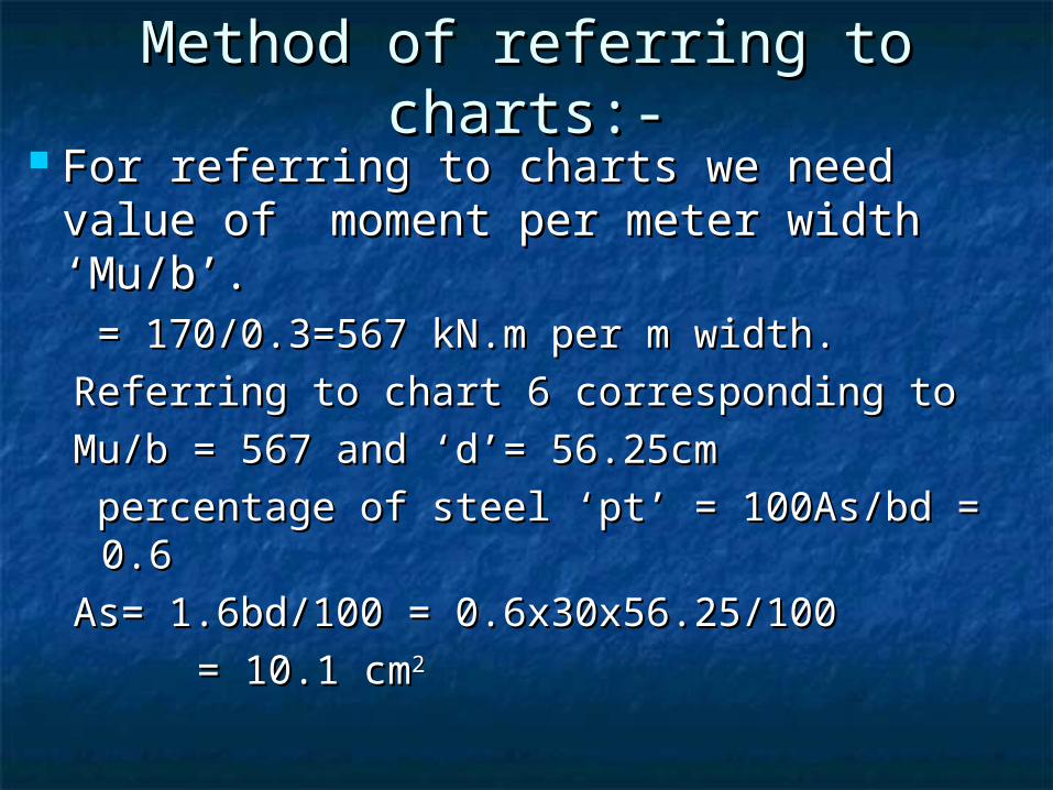
Method of referring to charts:-Method of referring to charts:- For referring to charts we need value For referring to charts we need value
of moment per meter width ‘Mu/b’.of moment per meter width ‘Mu/b’. = 170/0.3=567 kN.m per m width.= 170/0.3=567 kN.m per m width.
Referring to chart 6 corresponding to Referring to chart 6 corresponding to
Mu/b = 567 and ‘d’= 56.25cmMu/b = 567 and ‘d’= 56.25cm
percentage of steel ‘pt’ = 100As/bd = 0.6percentage of steel ‘pt’ = 100As/bd = 0.6
As= 1.6bd/100 = 0.6x30x56.25/100 As= 1.6bd/100 = 0.6x30x56.25/100
= 10.1 cm= 10.1 cm22
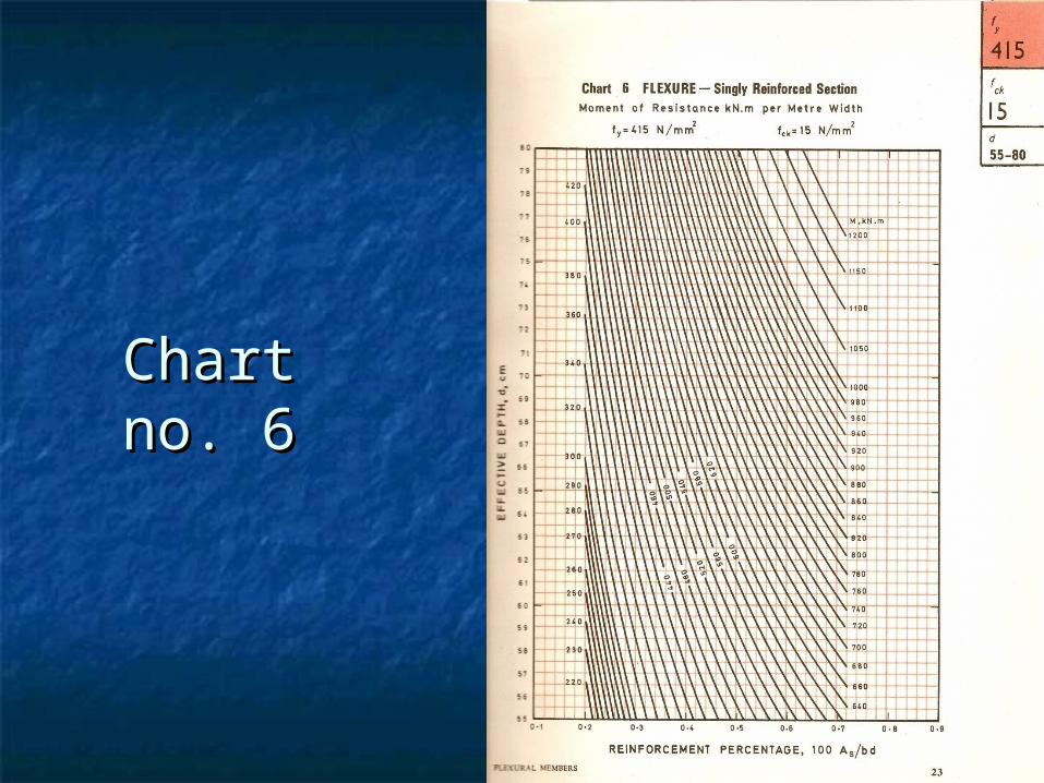
Chart no. Chart no. 66

Method of referring to Method of referring to tables:-tables:-
For referring to tables we need value For referring to tables we need value of Mu/bdof Mu/bd22
= 170x10= 170x1066
30x56.25x56.25x1030x56.25x56.25x1033
= 1.79N/mm= 1.79N/mm22
From table -1 pt = 0.594From table -1 pt = 0.594
As=1.594x30x56.25/100=10.02 cmAs=1.594x30x56.25/100=10.02 cm22
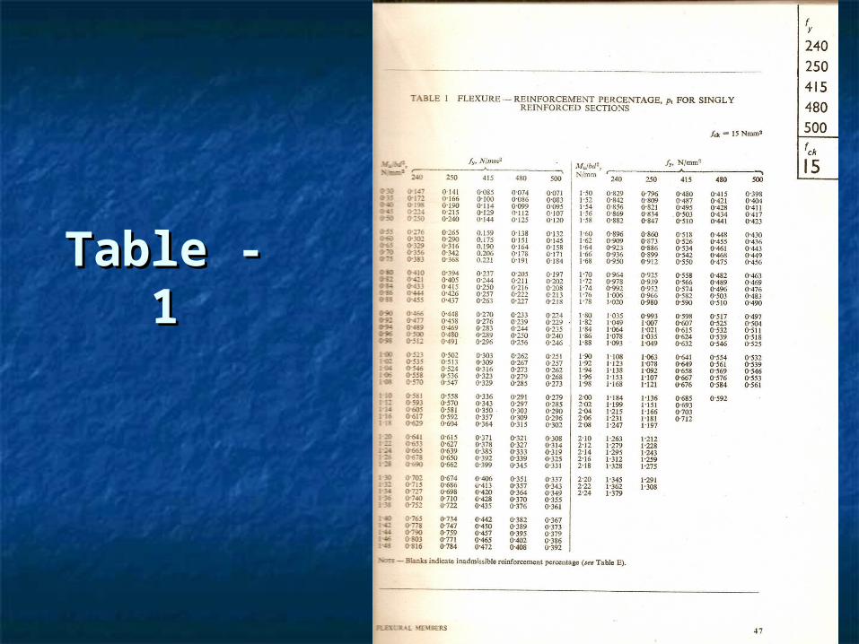
Table - Table - 11