![BachelorThesis: SimulationofReplicationandShardingwith ... · 2 1. Introduction windowinthetestedsystemsincreaseswithanincreasingworkload. However,[WFGR15]dis-coveredthatthemeasuredstalenesswindowisactuallyquiteimprecise.](https://static.fdocuments.in/doc/165x107/5f836c52f9607d06984df092/bachelorthesis-simulationofreplicationandshardingwith-2-1-introduction-windowinthetestedsystemsincreaseswithanincreasingworkload.jpg)
BachelorThesis 5.3
65
Bachelor Thesis DEVELOPMENT OF 3D ROBOT VISION SYSTEM FOR ROBOT ARM Student: Pham Quang Huy, Nguyen Matriculation number: 968058 First examiner: Prof. Dr. Peter Nauth Second examiner: Prof. Dr. Manfred Jungke Date of submission: 31 August, 2012
-
Upload
nguyen-huy -
Category
Documents
-
view
233 -
download
0
Transcript of BachelorThesis 5.3

Bachelor Thesis DEVELOPMENT OF 3D ROBOT VISION
SYSTEM FOR ROBOT ARM
Student: Pham Quang Huy, Nguyen
Matriculation number: 968058
First examiner: Prof. Dr. Peter Nauth
Second examiner: Prof. Dr. Manfred Jungke
Date of submission: 31 August, 2012

Statement
I conform to have written this bachelor thesis on my own and without any
assistance. No other sources were used except those referenced.
Frankfurt, 31.08.2012
_________________
Pham Quang Huy, Nguyen

Acknowledgements
It is a pleasure to thank those who made this thesis possible.
Firstly, I owe deepest gratitude to my lecturer, Prof. Dr. Peter Nauth, for pro-
viding me an opportunity to such an interesting work in my bachelor thesis,
and his invaluable guidance and support.
Also, this paper would have not been possible without the help of Mr. Wolf-
gang Grote and Mr. Dipl.-Ing. Robert Michalik. Their contribution is very
much appreciated by the assistance in the first phase of my bachelor thesis
and by giving numerous tips and advices during my work.
A special thank you goes to Mr. Adam Drazek and Mr. Lucas Berend for
their time and for their kind help and instruction.
I would like also to thank Prof. Dr. Manfred Jungke for his willingness to
stand in my side as the second reference.
Lastly, I am sincerely thankful to my family, my friends and student col-
leagues in TI Labor who have given me a lot of courage and continuous mor-
al support.

4
Abstract
This work aims to serve as an updated version of the 3D robot vision system
which is developed to guide the robot arm in TI-Labor at Fachhochschule
Frankfurt am Main. More specifically, the objectives comprise two key com-
ponents: remedy for shortcomings in the existing program, and addition of
new features through multiple-object recognition via their IDs accompanied
by follow-up calculation of coordinates for the robot arm.
The previous vision program was to detect and position a specific object – an
“Arizona tea” bottle – in the range less than one meter with LabVIEW and
Kinect camera. Thus, I continued using LabVIEW as the development tool
and Kinect as the hardware for acquiring objects’ images.
First, I tried to discover limitations of the old program and improve them
through different approaches. The old program recognizes an object by ex-
tracting it from the background in depth image, matching its shape with a
shape template, and then checking the object’s color with a reference color. I
found that the depth image from Kinect was modified by the “Distance Mod-
ification” VI and converted to RGB image for shape matching. This resulted
in a blind region, where objects cannot be seen in depth image by the Kinect
camera. I corrected this by applying a more appropriate modification to en-
hance the depth image. In addition, I converted a depth image into a binary
image instead of an RGB-image since it provides more robustness for shape
matching of a single object. This new conversion also eliminates the blind
region mentioned above.
Next, I shift the focus of my thesis to detection and differentiation of more
than one object. Comparing two searching orders: “color matching first,
shape matching later” and “shape matching first, color matching later”, I
found the latter to be more efficient than the former. Therefore, based on the
“shape matching first, color matching later” searching order, I developed an

5
alternative image processing algorithm for searching and classifying different
object classes. By adjusting the positioning module of the previous program,
my program is able to locate center points of recognized objects, and convert
them into real life coordinates.

Contents
6
Contents
1 INTRODUCTION .................................................................. 8
2 THE ROBOT VISION SYSTEM IN TI-LABOR .......................... 10
2.1 THE XBOX KINECT ........................................................................................ 10 2.2 THE EXISTING VISION PROGRAM ...................................................................... 12
2.2.1 The searching agent ............................................................................ 13 2.2.2 The positioning module ....................................................................... 14
3 IMPROVEMENT OF LIMITATION IN THE CURRENT VISION PROGRAM ............................................................................... 16
3.1 PROBLEM ANALYSIS ...................................................................................... 16 3.2 SOLUTIONS DISCUSSION ................................................................................ 22
3.2.1 Solution at the first glance .................................................................. 22 3.2.2 Solution with new depth map modification and binary image ........... 22
3.3 REALIZATION OF THE IMPROVEMENT ............................................................... 24 3.4 DEPTH MAP MODIFICATION: NEW VERSION VERSUS OLD VERSION ........................ 26
4 UPDATE OF THE VISION PROGRAM – MULTIPLE OBJECT CLASSES RECOGNITION AND DIFFERENTIATION ...................... 29
4.1 THEORETICAL BACKGROUND ........................................................................... 29 4.2 COMPARISON BETWEEN TWO SEARCHING PROCESSES ......................................... 33
4.2.1 What are two searching processes ..................................................... 33 4.2.2 Analysis ................................................................................................ 35 4.2.3 Comparison ......................................................................................... 35 4.2.4 Pre-processing methods for color image ............................................. 38 4.2.5 Final decision on searching order ........................................................ 42
4.3 REQUIREMENTS ANALYSIS OF PATTERN RECOGNITION ......................................... 43 4.4 REALIZATION ............................................................................................... 46
4.4.1 “Kinect Initialisierung” and “Kinect Ausgabe” subVIs ....................... 46 4.4.2 “Disztance Modifikation 2” subVI: ..................................................... 47 4.4.3 “To binary” subVI: ............................................................................... 47

Contents
7
4.4.4 “Shape search 4” subVI: ...................................................................... 48 4.4.5 “Color search 4” subVI: ....................................................................... 49 4.4.6 “Matches array processing” subVI: .................................................... 49 4.4.7 “Database 2” subVI ............................................................................. 51
4.5 POSITION DETERMINATION AND OTHER SUPPORTING SUBVIS ............................... 51 4.5.1 “Coordinates 2” subVI: ........................................................................ 52 4.5.2 “Diameter” subVI: ............................................................................... 53 4.5.3 Supporting subVIs for displaying purpose ........................................... 53
5 PROJECT SUMMARY AND PERSPECTIVES .......................... 56
5.1 SUMMARY .................................................................................................. 56 5.2 FUTURE PERSPECTIVES .................................................................................. 57
6 TABLE OF FIGURES ............................................................ 59
7 REFERENCES ...................................................................... 60
8 APPENDICES...................................................................... 62

1 Introduction
8
1 Introduction
Today in technological development, a huge range of innovation in robotics
triggers a realization of automation process in different areas of life. Vast
majority of industries, factory production lines, etc. implement computer-
controlled robotic systems as an important role in their operation .Mimicking
human bodies’ functions, robotic systems process and make proper decisions
based on image information given by corresponding vision systems. Togeth-
er, they form uniform systems referred to as Vision guided robotic systems.
“A Vision Guided Robot System comprises three core systems including ro-
botic system, vision system, and component bulk handling system (hopper or
conveyor system)” (Vision Guided Robotic Systems).
As observed, a vision system, in some degree, can be regarded as a key factor
for automating systems with an enhanced level of autonomy. Imitating hu-
man vision’s principle in which information is absorbed through the eyes and
processed in the brain for final decisions, the robot vision system consists of
two main hardware (a camera, a microprocessor or a computer) and asso-
ciated software. The software is a bunch of different processing and analysis
algorithms which aim to extract information from image data and use it to
solve different required tasks, such as object recognition, object tracking,
scene analysis, or navigation by image. This way, a vision system in a broad
sense can offer excellent versatility and flexibility for same computer-
controlled systems adaptable to many areas for many purposes, just by hav-
ing a suitable camera and software.
From an academic perspective, a vision guided robotic system in TI-Labor is
built with one robot arm, an Xbox Kinect as a camera, and a computer for
processing and controlling the whole system. The goal of the robot vision is
to give the robotic system a visual perception of its environment. The current
vision system should be able to cope with such tasks as searching and identi-
fying objects, calculating their positions, and sending information regarding

1 Introduction
9
their coordinates to the robot arm. The robot arm, in return, acts autonomous-
ly to grab an object and perform another task – for example, grabbing a Cola
bottle and pouring it into a cup.
Figure 1: The robotic system in TI-Labor, FH Frankfurt am Main.

2 The robot vision system in TI-Labor
10
2 The robot vision system in TI-
Labor
The vision system in TI-Labor comprises a computer, an Xbox Kinect cam-
era, and a vision program. In the first part of this chapter, I am going to intro-
duce the core hardware component in the vision system, Kinect camera, then
discuss about its hardware construction and provided functionalities. The
second part will deal with the existing vision program for the robot vision
system, including a brief introduction to the task of the program, together
with an explanation of how the program utilizes the features of the Kinect to
solve the task requirement.
2.1 The Xbox Kinect
Kinect is a motion sensing input device for the Xbox 360 video game console
and Windows PCs. Based around a webcam-style add-on peripheral for the
Xbox 360 console, it was developed by Microsoft along with Israeli develop-
er PrimeSense to enable users to control and interact with the Xbox 360
without the need to touch a conventional game controller 1. “PrimeSense
developed a system that can interpret specific gestures, making completely
hands-free control of electronic devices possible by using an infrared projec-
tor and camera and a special microchip to track the movement of objects and
individuals in three dimensions” (Microsoft Corporation, 2010), (MIT).
Thanks to the power of both software technology from Microsoft and hard-
ware technology from PrimeSense, the new type of control is made possible
by full-body 3D motion capture, facial recognition and voice recognition ca-
pabilities.
1 Microsoft Corporation, 2009 June 1. "Xbox 360 - "Project Natal" 101".
2 The robot vision system in TI-Labor
11
Figure 2: Sensors and specs of Kinect camera. (Kofler, 2011)
Regarding its construction, Kinect features “an RGB camera, a depth sensor
and a multi-array microphone running proprietary software” (Totilo, 2010).
The RGB camera is a CCD sensor, which provides an 8-bit VGA resolution
(640 x 480 pixels) video stream with a Bayer color filter. On the other side,
the depth sensor consists of an infrared laser projector combined with a mo-
nochrome CMOS sensor. The sensor can capture video data under any am-
bient light condition, since it is not designed to register visible light. The mo-
nochrome depth sensing video stream is also in VGA resolution (640 x 480
pixels), but with 11-bit depth, meaning 2,048 levels of sensitivity. The depth
sensor on Kinect is categorized as a time-of-fly (TOF) camera. The principle
of this type of camera is the same as that of sonar systems. An image is cap-
tured by emitting an invisible light pulse to the scene; the light then reflects
off of the object’s surface back to the dedicated sensor. When knowing the
back-and-forth-travelling time of light, the distance is derived for each pixel
within the sensor chip. With this technique, a 2D image is produced showing
the distance to points in a scene from a specific point; a depth map is hence
created. Combining with a color image from the RGB camera, I can generate
a three-dimensional image in the camera’s field of view.

2 The robot vision system in TI-Labor
12
Figure 3: Illustration of how the Xbox Kinect works. (Carmody, 2010)
2.2 The existing vision program
The current vision program controlling the robot arm in TI-labor was devel-
oped by Mr. Lucas Berend as a work for his Bachelor thesis. The program
was well-adapted to the robotic system, and was successful in guiding the
robot arm to grab an object exactly.
The aim of his thesis is “to develop image processing software that allows an
autonomous robot arm for identifying and determining the position of a sin-
gle predefined object in less than one meter” (Berend, 2012). The object has
to be realistic in daily life, so Berend chose a beverage bottle – Arizona tea
bottle – as a target object. To achieve this goal, he developed a searching
agent to determine whether the Arizona bottle appears in the camera’s field
of view, and a positioning module, which handles the tilt angle of the cam-
era, other coordinate issues and measurement errors to locate a found object
in real 3D space.

2 The robot vision system in TI-Labor
13
See the Appendix 1 for the block diagram of the current vision program from
Mr. Lucas Berend.
2.2.1 The searching agent
To begin with, the bottle is identified based on two criteria, its shape
and its typical color. Before explaining how the searching agent
works in detail, it is worthy to point out that the searching process Lu-
cas Berend designed for his searching agent was “Shape matching
first, color matching later”. This means that the image processing pro-
gram first looks for an object in a scene having the similar shape to
the shape of the target object, then in series the program matches the
color of the object in a scene to the reference color to decide whether
the target object is found or not. There is another method to search for
an object, “Color matching first, and shape matching later”. As its
name suggests, the searching order in such way is totally reversed. I
did an experiment with the latter method in my thesis and made a
comparison between both methods’ performances. The full compari-
son will be presented in the section 4.2 of my papers, but the first ob-
servation shows, the latter method, “Color matching first, shape
matching later”, is not as effective as the former one.
In order to acquire information about shape and color of an object, the
use of both cameras, infrared (IR) camera and RGB camera, was tak-
en into account. The RGB camera provides color images; hence, color
information was directly taken and analyzed in the program. Shape in-
formation, on the other side, was more challenging to gather. In some
cases, the object’s color is so distinct that its shape can be extracted,
based on a big difference in color with the background. However,
when object’s and background’s colors are similar, it is not that easy
to get shape information only by using color images. An intensity or
depth image provides an efficient solution. The depth map from an IR
camera is modified by a subroutine (subVI) to fit the search range less
than one meter. Then the modified depth map is encoded into a RGB
image, which helps visualize the depth image of a scene. By means of
the depth image, the object’s shape is easily extracted from the back-
ground; complicated algorithms for shape recognition thus can be

2 The robot vision system in TI-Labor
14
avoided. With a simple matching tool for form searching, greater re-
sults are achieved with little effort.
In a serial operation, the searching algorithm undergoes two phases.
Phase 1: The algorithm used an intensity (or depth) picture of
an object as a template for searching. The template and a
Depth Image from the Kinect were fed to Shape module first
to do a shape matching on IR Image. Then this module re-
turned matching information and an optional rectangle.
Phase 2: A color sample of an object was used as a template.
The template, a RGB Image from Kinect as well as the option-
al rectangle from the previous phase were connected to the
Color Module. The Color module only found and matched a
color of the template within the optional rectangle, which was
defined by Shape module. A matching result was also returned
as an output.
The searching agent used matching information in the second phase to
decide if the object in the template was found.
2.2.2 The positioning module
After the target object is confirmed as found, the matching data from
Color Module is employed to calculate the position of the found ob-
ject. Matching information makes available some useful facts for po-
sitioning, for instance, coordinates of the center of the template, rota-
tion angles of the template, and boundaries of the template. Neverthe-
less, those are just relevant in the image frame and dissimilar in the
real life space. To properly convert coordinates in the image frame in-
to real life, the coordinate system needs to be defined; other essential
factors are considered to calibrate measurement errors.
The coordinate system is defined with an origin and three axes. The
positioning module has a functionality which lets a point chosen by
users be the origin. The angles of x- and y-axes can be adjusted by us-

2 The robot vision system in TI-Labor
15
ers corresponding to the tilt angle of the camera; hence object’s coor-
dinates are same as how they should be with regardless to how the
camera leans.
To deal with positioning and error correction, Berend made measure-
ments to determine the opening angle of the Kinect camera. Since the
camera looks at objects with its angle of view, one object would be
seen having various lengths and sizes when its distance to the camera
changes. Therefore, a subVI was developed to convert the distance
values provided by the camera into an angle-independent Z-value;
from the Z-value and the respective angles X- and Y- coordinates are
calculated. With this approach, it should be possible to display each
pixel in three polar coordinates; measured lengths and distances re-
main the same in different perspective.
As stated in his Bachelor thesis, Lucas Berend claimed that the posi-
tioning module should obtain an average measurement tolerance, at a
distance to camera of 60cm to 100cm, less than 1 cm on each axis.

3 Improvement of limitation in the current vision program
16
3 Improvement of limitation in the
current vision program
During my development process, I had to explore the current program to un-
derstand deeply how the thing works. Through various tests, I discovered that
although generally the program works properly, there is oddity which could
hinder the expansion of the program in future. The program was supposed to
recognize an object in its whole searching range, except one region where an
object is undetectable: a blind region in depth image. This chapter is begun
with an analysis of a reason causing a blind region. Next, it is followed by a
presentation of a new approach to depth map modification as well as its reali-
zation. Lastly, a comparison was made to prove how advanced the new ap-
proach is to the old one.
3.1 Problem analysis
Firstly, to get an idea why there is a blind region, it is necessary to compre-
hend the Berend’s technique to modify the Kinect’s depth map and the struc-
ture of RGB image in LabVIEW.
Lucas Berend created a subroutine, so-called “Distanz Modifikation” subVI,
to convert the range of the depth map’s value into his specific needs. The
depth map is returned from Kinect as a 2D array with size of 640x480. Each
element in the array contains a distance value which could span from 0mm to
about 8m (the size of the TI labor). So the main purpose of the “Distanz
Modifikation” subVI is to limit the unspecified distance value range in the
depth map to the range of 490mm to one meter. Basically, the subVI deter-
mines whether a distance value is within a range set by 490mm and 1000mm,
and coerces the value to fall within the range. If the value is between 490mm
and 1000mm, it is kept unchanged. If the value is larger than 1000mm or
smaller than 490mm, it is forced to the same value as the upper limit or the

3 Improvement of limitation in the current vision program
17
lower limit respectively. After modification, the depth map’s elements con-
tain only the values from 490 to 1000 (in millimeter).
Figure 4: "Distanz Modifikation" subVI illustration
Regarding the digital RGB image structure, the IMAQ Vision Manual Con-
cept by National Instrument described “a RGB image is encoded in memory
as a red, green, and blue image. Color image pixels are a composite of four
values. RGB U32 images store color information using 8 bits each for red,
green, and blue planes. An additional 8-bit value goes unused. This represen-
tation ends up with 4x8-bit or 32-bit encoding” (National Instruments
Corporation, 2005).

3 Improvement of limitation in the current vision program
18
Figure 5: Number of Bytes per Pixel Data (National Instruments Corporation,
2005).
So as to display a pure blue, green or red color, a pixel value should be 255
(R,G,B = 0,0,255), or 65280 (R,G,B = 0,255,0), or 16711680 (R,G,B =
255,0,0) respectively.
Figure 6: Illustration of three color planes in RGB image model
3 Improvement of limitation in the current vision program
19
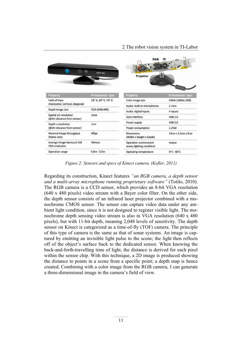
For visualization, the modified depth array is converted to a 32-bit unsigned
integer RGB image (RGB U32). Distance values in each element of the 2D
depth array become values of each pixel in RGB image. Due to the fact that
the values in the depth array range from 490 to 1000, the pixel values in RGB
U32 image spread from 0,1,234 to 0,3,232. It is noticeable that the red inten-
sity is always zero; the maximum intensity level in the green plane that can
take place is just 3, whereas in blue plane it is 255. So the red plane’s pixels
play no role, and the effect of the green plane in image is considerably small-
er than that of the blue plane. Only the blue plane contributes to displaying
the depth map. Consequently, the depth image in general is observed as a
bluish picture (Figure 7) having different regions with different intensity.
Figure 7: Visualization of depth map is a bluish depth image in Berend's program.
Foreground and background appears in very similar color in the image, which helps
an object be extracted easily for shape recognition.
1 2
3
3 Improvement of limitation in the current vision program
20
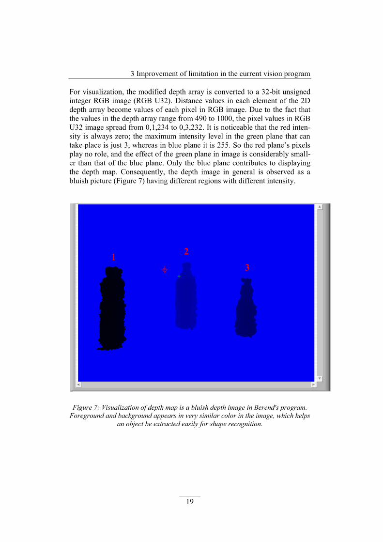
As be expected with this approach, image regions which have different pixel
values could be almost similar to each other, since they result in more or less
the same intensity values in the blue plane. In this case, a foreground and
background in the depth image (at distance of 490mm and 1000mm, equiva-
lent to 0,1,234 and 0,3,232 in R,G,B value) look nearly the same. There is
another distance range, which is corresponding to a pixel value of 0,2,232 to
0,2,234 or around these two values, appearing identical to the background
and foreground. That is a blind region. Whenever an object appears in this
region (approximately at a distance of 75cm to the Kinect), it is observed as
the same as a background and foreground, and hence is invisible in the depth
image. (See Figure 8)
Another drawback of the depth-map-to-RGB conversion is a change in con-
trast of an object’s image with respect to its position. This can be also ob-
served in both Figure 7 and Figure 8. Since a distance value is used directly
to be a pixel value, the intensity level in the depth image varies at different
object’s distances to the Kinect. At some positions, the depth image has a
good clarity, but at other positions (especially both ends of a searching range)
an object is very dim, which makes the shape matching function not operate
correctly any more. The shape recognition is, thus, dependent on object’s
distance to Kinect, which is not advantageous.

3 Improvement of limitation in the current vision program
21
Figure 8: Objects 2 and 3 are still in searching range, but invisible in depth image,
because they stay in the Blind region.
1 2
3
1 2
3

3 Improvement of limitation in the current vision program
22
3.2 Solutions discussion
The goal of this enhancement task is to make the shape matching operation
more robust and accurate in a specified searching range. First of all, the blind
region in the depth image has to be eliminated. Then the depth image itself is
improved, so that the shape detecting ability is more consistent within an en-
tire searching range and is unrelated to an object’s distance to Kinect. The
solution should also open possibility for future development in shape feature
extraction.
3.2.1 Solution at the first glance
It is obvious that the core reason of the blind region is the direct use
of distance values in the depth map. The range of value from 490 to
1000 is twice as much as the intensity range (8-bit depth - 256 differ-
ent values) of one color plane in RGB U32 image. Because of that,
one blue intensity value appears two times in the entire searching
range (from 490 to 1000). Therefore, the simple way to fix that prob-
lem is to reduce the whole range of value by a half (divide each dis-
tance value by 2), which was used by Berend as a solution in his pro-
gram. This answer is easy to realize and suitable for his requirement,
since his task is to detect an object in a range less than 1m. However,
this is not a global solution, because the correction is no longer valid
when users change a searching limit in difference from 1000mm.
3.2.2 Solution with new depth map modification and binary
image
To solve the problem universally, I developed a more appropriate
modification for the depth map. The new method can be divided into
two parts.
A maximum searching distance U is specified by users. Raw
distance values in the depth map are converted to a range R
set by 490 and U in the same manner as in the Berend’s me-
thod, with one exception: all raw distance values not falling
within the range are coerced to the value of U. This makes a

3 Improvement of limitation in the current vision program
23
foreground and background identical in a depth image after
modification.
Then, the converted range R from 490 to U is “digitalized” to
a range D with 256 step values (from 0 to 255) like a bit depth
of an 8-bit image plane. The “digitalization” is done with the
following formula:
𝒅 = 𝒓 − 490 ∗255
(𝑼 − 490)
With: r – An original distance value in the range R.
d – A distance value after being digitalized, in the
range D.
U – The upper limit of the range R.
Figure 9: Illustration of new modification method for depth map (the upper
limit U of range R is set to 1000)

3 Improvement of limitation in the current vision program
24
This approach lets the depth map be able to encode in RGB, HSL or
Grayscale Image without causing a blind region. The depth image still
features an advantage of easy shape extraction; however, the issue of
relationship between image contrast and object’s distance is still not
dealt with.
To overcome the remaining drawback, one more step was added. I
applied threshold to the depth image to create a “binary-depth” image.
Since a pixel value in a binary image can only be 1 (for objects) or 0
(for others), the “binary-depth” image has a consistent contrast be-
tween objects and a scene regardless of an object’s distance. The thre-
shold constant was calculated to segment objects from a scene, when-
ever they appear in a searching range.
The utilization of a binary image can be more advance by means of
applying binary morphological operations. These operations can be
used to enrich information, details and filter out noise in a binary im-
age before making a shape matching.
3.3 Realization of the improvement
Two new subVIs were built to implement my solution. One is to do the new
depth map modification and “digitalization”; the other one is to generate a
“binary-depth” image and operate binary morphologies. The models of the
two subVIs are explained below:
The “Distanz Modifikation 2” subVI
Figure 10: Distanz Modifikation 2 (subVI).vi

3 Improvement of limitation in the current vision program
25
The subVI takes 2 inputs: Array of depth In and Distanz. Array of depth
In is the depth map being returned from the Kinect, and Distanz (which is
input by users) is the upper limit U of the searching range R. The algorithm
to modify and “digitalize” the depth array is executed inside the subVI, and
then two outputs are returned. Array of depth OUT (shape) is a modified
and “digitalized” depth array with its values within the range D, while Array
of depth OUT (measure) is exactly the same as the Array of depth OUT
output in Berend’s “Distanz Modifikation” subVI. The second output is re-
served for objects’ location measurement in later steps.
The “To Binary“ subVI
Figure 11: To Binary (subVI).vi
The subVI takes 2 inputs and returns 2 outputs. The Array of depth OUT
(shape) output of “Distanz Modifikation 2” is converted into a grayscale im-
age, and that image is connected to “To Binary” subVI via Image Src
(Grayscale) input line. Distanz is the upper limit U of the searching range R.
The subVI calculates a threshold constant based on Distanz value to create a
binary image from Image Src (Grayscale). Before outputting, the binary
image is enhanced with the POpen binary morphology operation2 and other
particle filtering functions of IMAQ Vision. Two outputs of the subVI in-
clude Bin Image (display) for image displaying purpose and Bin Image
(process) for further image processing.
2 According to IMAQ Vision Concept Manual, POpen, which stands for the Proper-
Opening function, “is a finite and dual combination of opening and closing. It
removes small particles and smooths the contour of particles.” (National
Instruments Corporation, 2005)

3 Improvement of limitation in the current vision program
26
3.4 Depth map modification: New version versus
Old version
The two new subVIs were tested to check their performance in recognizing
an object’s shape. In this testing condition, the Shape matching function and
the form reference picture were the ones used in Berend’s program, to ensure
good and reliable results. The testing scenario was to detect a shape of “Ari-
zona Tea” bottle at five different distances to Kinect (50cm, 60cm, 70cm,
80cm and 100cm) with three different perspectives (left, right and center to
Kinect). The measurement was done two times; the first time with Berend’s
“Distanz Modifikation” subVI, and the second time with the two newly built
subVIs: “Distanz Modifikation 2” and “To Binary”. The matching scores in
each time were recorded and plotted on graphs to make comparison.
Figure 12: Block diagram illustrating the testing setup
Kinect

3 Improvement of limitation in the current vision program
27
Three charts below present the testing results.
As be observed, the first measurement’s graph always lied under the graph in
the second measurement, meaning that the two new subVIs produced more
decent overall performance in shape matching than the old subVI. With re-
gard to all three standing points to Kinect, the second measurement had more
or less consistent matching scores through the entire searching range, while
the matching scores in the first measurement showed more fluctuation. In
three figures below, the scores of the blue line reached maximum and some-
times slightly higher than the scores of the red line at the middle of searching
range (70 – 80cm), whereas at both ends of searching range, especially at the
far end, the scores of the blue line were relatively poor (they were lower than
the score of 300).
To conclude, the two new subVIs, “Distanz Modifikation 2” and “To binary”,
support the Shape matching function more effectively and show an obvious
improvement in shape recognition.
Figure 13: Matching score plot comparison - object in the Left side to Kinect
400450
570520
260
610650
590530
460
0
100
200
300
400
500
600
700
800
40 50 60 70 80 90 100
Mat
chin
g sc
ore
(0
-1
00
0)
Distance to Kinect (in cm)
Distanz Modifikation subVI Distanz Modifikation 2 + To Binary subVIs

3 Improvement of limitation in the current vision program
28
Figure 14: Matching score plot comparison - object in the Right side to Kinect
Figure 15: Matching score plot comparison - object in the Center to Kinect
380450
650
520
270
670630 640
520450
0
100
200
300
400
500
600
700
800
40 50 60 70 80 90 100
Mat
chin
g sc
ore
(0
-1
00
0)
Distance to Kinect (in cm)
Distanz Modifikation subVI Distanz Modifikation 2 + To Binary subVIs
410
540580
510
250
720 730
620
520
450
0
100
200
300
400
500
600
700
800
40 50 60 70 80 90 100
Mat
chin
g sc
ore
(0
-1
00
0)
Distance to Kinect (in cm)
Distanz Modifikation subVI Distanz Modifikation 2 + To Binary subVIs

4 Update of the vision program
29
4 Update of the vision program –
Multiple object classes
recognition and differentiation
After the remedy in a depth image, the additional feature of the vision pro-
gram, multiple-object recognition via their OIDs (Object ID), was carried
out. The first part of this chapter discusses the theory behind a recognition
and differentiation task. Secondly, the comparison between two searching
orders is presented to figure out which one should be used in further develop-
ing steps. Based on the chosen searching order, the next part of this chapter
shows how the theoretical algorithm was adapted to specific requirements of
the situation by means of available tools. It is followed by the introduction to
new subVIs which were built to realize the algorithm. Finally, the adjustment
of the existing positioning module to suit the newly-built vision system as
well as another supporting subVIs are the main topic in the last part of this
chapter.
4.1 Theoretical background3
A robot vision is categorized as an intelligent system which executes intelli-
gent algorithms to perform complicated tasks (Nauth, 2011).
There are many intelligent algorithms for different applications such as medi-
cal diagnosis, computer vision, and autonomous navigation system in a com-
plex environment; however, the intelligent algorithm which is concerned here
is dedicated to pattern recognition task.
3 All theoretical knowledge in this section is referenced to the lecture note of the
“Embedded Intelligent Systems” course from Prof. Dr. Peter Nauth

4 Update of the vision program
30
According to the Embedded Intelligent Systems lecture, Pattern Recognition
is defined as:
“An Analysis of a complex signal (= pattern) in order to recognize objects
and calculate their properties or to understand the meaning of the pattern in
context with a task and environment” (Nauth, 2011).
In general view, the algorithm is operated in a sequence of processing steps,
which is showed in the Figure 16. An analog signal representing information
(= patterns) from outside environment, such as image, sound or voice signal,
video signal, is acquired by digitalization. This acquisition step produces a
digital signal containing those information (=pattern). The digital pattern is
then segmented into objects. After that, characteristic parameters, which are
typical to each object, are calculated and extracted. A classification step at-
tempts to assign each object to one of a given set of classes based on those
characteristic parameters and classification models. The result from pattern
recognition is a number of classified objects. They could be words or sen-
tences in voice signal (speech recognition) or in picture (handwriting recogni-
tion), recognized objects (robot vision), or disqualified products (vision in-
spection system).
Figure 16: Processing steps of a Pattern Recognition System (Nauth, 2011).

4 Update of the vision program
31
Detail operations in each step of the pattern recognition algorithm are sum-
marized in following:
Signal acquisition and pre-processing
A pattern contained in an analog signal can be modeled in mathe-
matics as a set of functions of multiple variables:
𝑓( 𝑎 ) =
),...,(
.......................
),...,(
),...,(
21
212
211
KL
K
K
aaaf
aaaf
aaaf
A single function 𝑓𝑖( 𝑎 ) could be a brightness intensity function
with respect to spatial coordinates (image signal) or a pressure func-
tion with respect to time (voice or sound signal)
The analog pattern signal 𝑓( 𝑎 ) is acquired and digitalized in differ-
ent manners, either by an Analog-to-Digital converter or through a
device outputting directly digital data. After digitalization, a digital
signal 𝑓 𝑠 contains discrete sampling values of the pattern signal
and is stored in memory for further computation.
The pattern in digital form can be exposed to noise and other errors
which can hinder the next pattern recognition steps to be performed
successfully, especially in the segmentation part. Therefore, it is es-
sential to have some pre-processing methods after acquisition and
digitalization, such as contrast enhancement, demodulation of sig-
nals, low pass filtering, high pass filtering, etc.
Segmentation
Objects of interest are separated from the digitized pattern and be-
come objectives for the succeeding processing procedures.
To so doing, segmentation goes through 2 steps:
o Thresholding: Splitting the pattern into two subdivisions: fo-
regrounds and backgrounds. Foreground and background
samples are identified based on certain threshold limits

4 Update of the vision program
32
which can be calculated automatically inside the algorithm or
be set in advance by users
o Labeling: Grouping all adjacent foreground samples into a
single object and each object is assigned by a unique object
number.
The output of segmentation is a number of M objects and each of
them is labeled by an object number m.
Feature extraction
During feature extraction, a feature vector (parameter vector) x with
N features is calculated for each of M objects
x = (x 1 , x 2 , …..xN
)T
The features or parameters must characterize properties of the ob-
jects as significantly as possible. Some frequently used parameters
in image processing are:
o Grayscale image
-Number of holes in object
-Area A and circumference U of object
-Circularity factor C=U²/A
-Position and Orientation of Object
-Mean and variance of brightness within object
o Color image
-Intensity of each colour channel
-Mean and variance of each colour cannel of objects
Classification
Classification is a method of decision making and assigns a feature
vector x to a suitable class i.
Reference models for each class i have to be predefined in the
training phase in priority to the classification phase.

4 Update of the vision program
33
Based on those predefined models from training phase, the classifi-
cation phase allocates each object with a feature vector x to each
class by various executing methods, such as Geometric classifier,
Box classifier, Linear statistical classifier, etc.
Depending on the applications, not all of the steps of pattern recognition
mentioned above might be necessary.
4.2 Comparison between two searching processes
The theory above describes the pattern recognition algorithm for one single
signal. However, in the current vision system, the Kinect camera returns two
signals for processing, a RGB image and a depth map. The algorithms
processing both signals can be operated simultaneously in parallel or sepa-
rately in series. For objects detection with robustness and accuracy, the series
operation is more preferable. Therefore, in this part, the comparison between
two orders to process the signals in serial operation is considered to deter-
mine which one is more appropriate to implement the multiple-objects recog-
nition and differentiation task.4
4.2.1 What are two searching processes
First of all, let look at what two possible searching orders in a serial
algorithm are.
Searching process 1: (the method used in the Berend’s pro-
gram)
The algorithm is executed in two phases. In the first phase, a
depth picture of an object is used as a template for shape
matching. The template and a Depth Image from Kinect are
fed to the Shape module to perform a shape matching first
on depth image. Then the Shape module returns an optional
rectangle for the second phase, and matching results.
4 The comparison was done to test the ability to recognize objects of both searching
orders. The differentiation ability was not taken into account in this part.

4 Update of the vision program
34
In the second phase, a template for color matching is a color
picture of an object. The templates, a RGB Image of a scene
as well as the optional rectangle from the Shape module are
connected to the Color module to perform color matching on
color image. The Color module only searches for a color in
the template within a region of color image defined by the
optional rectangle. It then returns matching data as its output.
The program finally gives a confirmation about whether an
object is found or not based on the matching data of both
phases.
Searching algorithm 2: (The one I made an experiment with)
The algorithm also takes two phases. In contradiction to the
algorithm 1, the algorithm 2 uses an color picture of an ob-
ject as a template for color and shape searching in the first
phase. The template and a RGB Image from the Kinect are
fed to the Color + Shape module to perform a color pattern
matching on color Image. This module returns matching re-
sults and an optional rectangle containing a found thing.
In the second phase, a depth (or intensity) picture is used as a
template for shape matching. The template, a Depth Image
from Kinect as well as the optional rectangle from the pre-
vious phase are connected to the Shape Module to do shape
matching on depth image. The Shape module only finds and
matches a shape in the template within a region of depth im-
age defined by the optional rectangle. Matching data are also
returned as its output.
The program then uses both matching results from two phas-
es to make decision if an object is found.
Note: The optional rectangle returned in the first phase defines a
search area for the next phase operation; therefore, it is essential fac-
tor to reduce ambiguity, increase accuracy and also speed of the
whole searching algorithm. An optional rectangle must be larger than
or equal to a size of a template picture of the second phase.

4 Update of the vision program
35
4.2.2 Analysis
The second phase of both searching algorithms needs and depends on
an optional rectangle from the first phase to operate efficiently. If the
first phase does not find any objects, it will return no optional rectan-
gle. This means, a module in 2nd
phase will searching for a template
on the whole image and it is time-consuming. And if the second phase
would find something, it would be insufficient to make any conclu-
sion because the program finds nothing in the previous image. The in-
formation in one phase is not enough to conclude an object found.
Therefore, the first phase is important and the second phase provides
information to confirm surely an object is found.
The accuracy and speed of matching tasks in both color and depth im-
age depend on how big a search area is and how an object of interest
is different from a background.
The first phase has to search in entire image because there is no clue
to claim in which part of the image would be an object. As stated in
the theory, to make a searching easier, the image from Kinect has to
be pre-processed to make an object different from a background
Since the 1st phase is important and more challenging, in next part I
will compare the 1st phase of two algorithms, both of them do search-
ing in entire frame, but one in color image and the others in IR image.
4.2.3 Comparison
Firstly, two searching tasks in color and depth image are performed
without any pre-treatment. Pure templates and images from Kinect
were used here. As the result, the matching score in RGB image was
about 450 – 600, sometimes it fell below 450 depending lighting con-

4 Update of the vision program
36
dition; while the matching score in Depth Image was around 550 and
more than 700. (See Figure 17)
In the two screenshots below, it is also noticed that the matching in
RGB was not quite accurate. The overlay was fine in case of class 1
object, but it did not totally lie on class 0 object. Although the pro-
gram found both bottles, the matching scores were in an average
range and the incorrect overlay of class 0 object would later lead to
incorrect position determination. Sometimes the program said that ob-
jects were found but actually it detected completely different things
(The program sometimes recognized a curtain instead of the red Ari-
zona bottle). However, in IR mode, it is very good; both objects were
found and overlaid correctly with high matching scores.
At the first glance, searching in depth image seems to have an advan-
tage over searching in color image. Thus, pre-processing methods will
be applied in next part to improve result of searching in RGB image.

4 Update of the vision program
37
Figure 17: Comparison of matching scores in RGB and depth without pre-treatment.

4 Update of the vision program
38
4.2.4 Pre-processing methods for color image
Some methods to improve a RGB image before processing are dis-
cussed here.
Two ways which I tried to enhance matching results in RGB image
are to utilize HSL format instead of RGB format, and to use color
threshold for color Image from Kinect before letting it go through
Color + Shape module.
The first method – using HSL color space. (National
Instruments Corporation, 2005)
As mentioned above, color matching can be strongly depen-
dent on lighting condition. RGB color space encodes color
and luminance (brightness intensity) information in light to-
gether in three components Red, Green and Blue; thus when
light intensity changes, a different color will be observed by
the Kinect5 and the program makes wrong decision due to
that (however, the fact is that color of an object is un-
changed). HSL color space encodes light information in
another way. The luminance component of light is separated
from the color information. This property leads to more ro-
bust color representation which is independent of lighting
condition (brightness) variation. Since color image outputted
Kinect is in RGB format, a transformation from RGB to HSL
format for Image from Kinect and template image has to be
done explicitly to ensure that color detection is executed in
HSL mode. However, the receiving result was not much bet-
ter; there was only slightly increase in matching scores and a
wrong detection still happened when a background was not
“clean”!
5 The Kinect camera outputs a color image in RGB format.

4 Update of the vision program
39
The 2nd
way – using color threshold.
The Image from Kinect was applied threshold in color
planes, so that a background was excluded from a foreground
object as much as possible. The output from color threshold
module was a searching area in form of a rectangle (a red
rectangle in the Figure 18), which hopefully contained an
wanted object This rectangle was connected to the Optional
rectangle input of Color + Shape module and limited the
module to concentrate only on a region of image containing
objects.
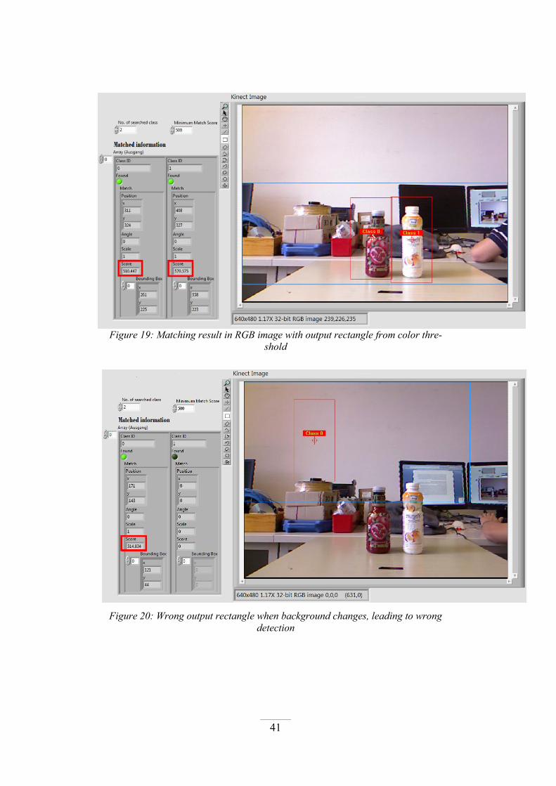
The Figure 18 below shows a color threshold in RGB color space.
The threshold can be applied in RGB and HSL color mode, but I
found that in this situation threshold in HSL mode did not give such a
good and accurate output rectangle as in RGB mode. When connect-
ing the output rectangle to Color + Shape module, the searching re-
sult is shown in the Figure 19. (The output rectangle is the blue one in
Figure 19)
As be seen, the searching result is better. The class 0 object was rec-
ognized more accurately with nearly correct overlay on top of it, al-
though the matching score was still in the same range as in the case
without threshold.
Nevertheless, as be mentioned before, RGB color mode is sensitive to
lighting condition. Thus when light intensive changed in the room or
in the background, the threshold constants were no longer correct.
This means the threshold range have to adjust again to get correct and
a good searching area, but this is also equivalent that the program was
not automatic anymore. The screenshot in Figure 20 illustrates the
case of when the monitor in background was turned on, with the same
threshold constant the search area (blue rectangle) was totally differ-
ent. The detection was also wrong. (See Figure 20)

4 Update of the vision program
40
Figure 18: Result of threshold in RGB model and the output rectangle.
4 Update of the vision program
41
Figure 19: Matching result in RGB image with output rectangle from color thre-
shold
Figure 20: Wrong output rectangle when background changes, leading to wrong
detection

4 Update of the vision program
42
To conclude, the threshold method seems to give a better result, but it
is not robust in case of changing lighting condition, also the match
score here still does not catch up with the one of searching in IR im-
age without pre-process.
Other methods:
One way that Mr. Michalik suggested is to use many tem-
plates (more than five pictures) of an object in different illu-
minating conditions. Each object is then searched according
to different templates. This will increase a chance of finding
an object and the lighting problem can be solved as well.
This is a good approach, but I think using many templates
will slow down the algorithm. Since the program would be
set to detect multiple objects, in this case a number of tem-
plates needs to be searched will be multiplied with a number
of subjects. Moreover, the program is supposed to be able to
learn a new object class automatically in future development,
and a template would be created inside the program by itself.
So using multiple templates to search one object is not a
suitable solution for the learning phase in future.
4.2.5 Final decision on searching order
Processing an entire RGB image on the first hand to match an object
did work, although the results were not quite accurate. In some cases
an object could be detected quite well, but sometimes the matching
function could not recognize an object or detect a wrong thing. Over-
all, with some pre-treatments the second searching order, which per-
forms matching on RGB image in the first phase, can be work as an
alternative method to search objects; however it was found not as ef-
fective as the other searching order.
Regarding the first search process, which uses a depth image in the
first phase, a monochrome depth image by itself is very robust in
shape matching. But if it is applied threshold to create a “binary-
depth” image, the matching effect can even be better. As be pointed
out in the previous chapter, a binary image solves a problem of differ-

4 Update of the vision program
43
ent lighting condition and a change in contrast of an image. Further-
more, a binary image also provides a promising approach in the learn-
ing phase. Users can snapshoot a new object in a “binary-depth” im-
age; the program will save two corresponding pictures in binary and
in color formats. The binary image can be used directly as a template
to search that object later on, and a small central part of the color pic-
ture will be extracted to be a color template for color matching phase.
Therefore, I decided to make use of the first searching order in my
program to implement the pattern recognition algorithm for objects
differentiation.
4.3 Requirements analysis of pattern recognition
The aim of the pattern recognition system in the updated robot vision system
is to detect multiple objects and differentiate them into different classes. In
order to do so, the steps of the general pattern recognition in theory need to
be customized in accordance with the “Shape matching first, color matching
later” searching order, and by means of actual equipments. This section dis-
cusses detailed operation in each step of the customized pattern recognition
algorithm.
Signal acquisition:
This step is done with the help of the Kinect camera. Color image
and depth map from a scene are acquired simultaneously through
Kinect sensors and are outputted directly in digital form. Therefore,
there is no need of an analog-to-digital conversion in this step.
Those signals are accessible in the later steps.
With respect to the chosen searching order, the processing of depth map is
carried out first to extract shape information, and then color information is
made use. The following steps, including Pre-processing, Segmentation and
Feature extraction in “binary-depth” image, process the depth map only. The
color image is reserved and is further processed the in Color feature extrac-
tion step.

4 Update of the vision program
44
Pre-processing:
As be mentioned, the depth map directly from Kinect contains dis-
tance values in a broad range, which is more than the interest infor-
mation. Thus, the range of values needs to be limited, and also the
depth map requires a modification to be properly converted into
depth image for shape matching.
Segmentation
After the pre-processing steps, the depth image is returned in grays-
cale image format. Binarization, which is the first step in segmenta-
tion, is performed by applying threshold to the grayscale image. The
threshold boundaries are calculated so that any pixels having values
in a setting searching range (belonging to objects) will be set to val-
ue of 1 (foreground), whereas the other pixel are assigned to the
value of 0 (background). The “binary-depth” image is created as an
output of the threshold phase.
Next, all foreground pixels the “binary-depth” image, which are in
neighbor, are grouped and labeled as one object. The result of labe-
ling is the number of segmented objects with their assigning object
number.
As the result, all objects within the image and a defined searching
range as well as their object numbers are known. However, what
those objects represent is not identified, whether an object is a bottle,
a table or just a noise particle. This is done by feature extraction and
classification.
Feature extraction and classification in “binary-depth” image:
In “binary-depth” image, an object shape is a factor of interest to
distinguish different types of objects. The feature vector for each
segmented object contains just one parameter, a shape matching
score. The shape matching score is calculated based on how an ob-
ject is similar to a shape template; a score of 1000 equals to perfect
similarity and a score of 0 is for total dissimilarity. The shape tem-
plates for each class are defined in advance and already known.

4 Update of the vision program
45
Classification is done by ranking the shape matching scores to all
shape templates of one segmented object; highest matching score
with a class's shape template yields the object a place in that class.
This step is repeated for all segmented objects. The results could be
different objects classified in a same class.
Feature extraction and classification in color image
A color of an object is employed to differentiate objects which are
segmented in the Segmentation step. The feature vector for each ob-
ject has one feature, a color matching score. In the same manner as
in “binary-depth” image, the matching score is evidence for how a
color on an object is close to a color template, and color templates
for each object class are also trained in priority.
Classification phase is identical to that in the Feature extraction and
classification in “binary-depth” image step. An object is categorized
to a class having a highest matching score to it.
This step is also repeated for each segmented object. The results
could be different objects having a same class ID.
Since after executing the above steps there are two classification results in a
“binary-depth” image and a color image, one more step is added to the whole
algorithm to synthesize the two results and give a final confirmation about
which class each object is classified to.
Synthesis step:
The first phase in this step deals with sorting a color matching scores
of all objects which were classified in a same class. Objects having
the color matching score above a certain value are determined to be-
long to that class. The same procedure is also done for shape match-
ing scores.
Up to this point, each object has two class IDs, one is assigned from
shape matching and the others is from color matching. Those two
class IDs are then compared with each other. A class ID of an object
4 Update of the vision program
46
is finally verified only if both of its class IDs have an agreement.
Otherwise, an object gets no class ID.
4.4 Realization
All the steps in the customized pattern recognition algorithm were realized
and implemented in the vision program with the help of the following sub-
routines or subVIs.
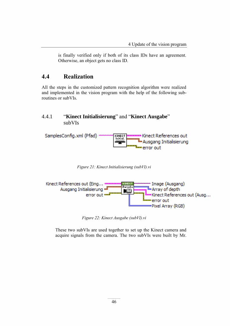
4.4.1 “Kinect Initialisierung” and “Kinect Ausgabe”
subVIs
Figure 21: Kinect Initialisierung (subVI).vi
Figure 22: Kinect Ausgabe (subVI).vi
These two subVIs are used together to set up the Kinect camera and
acquire signals from the camera. The two subVIs were built by Mr.

4 Update of the vision program
47
Adam Drazek to group the Kinect configuration VIs6 for convenient
use and avoiding mistakes when connecting those configuration VIs.
The first subVI, “Kinect Initialisierung”, takes an input as a path to a
configuration file in hard disk. The “Kinect Ausgabe” subVI is con-
nected after the first one and is placed inside the while loop to conti-
nuously acquire data from Kinect. From the second subVI’s output
side, color image, array of depth (or depth map) and pixel array of
RGB image can be received.
4.4.2 “Disztance Modifikation 2” subVI:
The newly-built subVI, which was introduced in the section 3.3, ex-
ecutes the pre-processing techniques mentioned above to modify the
depth map from Kinect in the Pre-processing step.
4.4.3 “To binary” subVI:
Binarization phase in the Segmentation step is done straight forward
by this newly-built subVI, also be introduced in the section 3.3. Some
VI functions from IMAQ are also made use in this subVI to recover
6 The Kinect configuration VIs for LabVIEW are provided by Open Natural Interac-
tion (OpenNI), including CreateContext.vi, Initialise Depth.vi, Initialize Im-
age.vi, GetMap.vi, GetImage.vi, Display Image.vi, Wait on Update.vi

4 Update of the vision program
48
objects’ forms and filter out noise, such as POpen Morphology, Fill
hole VI, Remove Particle VI and RejectBorder VI. The “binary-
depth” image is created as an output of the “To binary” subVI.
Another new subVI, “Shape search 4” subVI, which will be pre-
sented shortly below, is in charge of the labeling phase in the Seg-
mentation step.
4.4.4 “Shape search 4” subVI:
Figure 23: Shape search 4 (subVI).vi
The first responsibility of this new subVI is to handle the labeling
phase in the Segmentation step. One of the outputs of this subVI –
Optional Rectangle OUT – is an array of boundary rectangles in
which objects are fitted. Each boundary rectangle corresponds to each
segmented object, and the indexes in array of the boundary rectangles
represent the object numbers.
This subVI also deals with Feature extraction and classification in
“binary-depth” image as its second job. The subVI takes a “binary-
depth” image from the “To binary” subVI and the array of boundary
rectangles to perform feature extraction and classification based on
predefined shape templates (shape templates are binary pictures of
representative objects of each class which are stored in hard disk of a
PC). The result of this operation is a matches array containing all
matching information of each object.
The “Shape Match Tool” VI from IMAQ Vision was utilized to
build this subVI. The two mentioned operation are accomplished by
the “Shape Match Tool” VI. Moreover, the tool from IMAQ Vision
can detect objects regardless of objects’ sizes and rotation angles.

4 Update of the vision program
49
4.4.5 “Color search 4” subVI:
Figure 24: Color search 4 (subVI).vi
The subVI performs the Feature extraction and classification in
color image step. The core element of this subVI is the “Color Pat-
tern Matching” VI from IMAQ Vision. The boundary rectangle
which is returned from the “Shape search 4” subVI was used as an
optional rectangle input for the “Color Pattern Matching” VI to lim-
it a searching area in an image frame. The important outputs include a
matches array containing all matching data, such as matching score,
position of matched point, angle, etc, and an array holding a corres-
ponding classified ID to each object.
4.4.6 “Matches array processing” subVI:
Figure 25: Matches array processing (subVI).vi

4 Update of the vision program
50
The subVI was built to carry out the last step in the algorithm, which
combines information from both shape and color matching steps. The
operations which were described in the section above were imple-
mented in this subVI. However, one issue was noticed, that is the
matching information from shape matching was not useful as sup-
posed. Objects were classified to wrong classes because the shape
matching scores between different classes were very similar. This
means objects’ shapes were not well differentiated by using the
“Shape match tool” VI from IMAQ Vision. Therefore, the Shape
Matched input was taken out from the “Matches array processing”
subVI. Only color information is employed to make final decision
about a class ID for each object.
The most important output from this subVI is the Match info array.
Each element of the array is a cluster of 6 elements, which represents
information about of each classified object. The information includes:
Class ID:
The ID of the class which an object belongs to
Found:
A Boolean variable shows whether an object is detected or not.
Position:
A cluster of three elements contain three real coordinates of an ob-
ject in x-, y- and z-axis. Those coordinates can be transferred to the
robot arm to grab an object.
X CCD
A value shows the x position on image frame of a detected point of
an object. It is used for the purpose of displaying the detected point
on screen.
Y CCD
A value shows the y position on image frame of the detected point of
an object. It is used for the purpose of displaying the detected point
on screen.
Optional rectangle
An array represents a boundary rectangle of an object.

4 Update of the vision program
51
4.4.7 “Database 2” subVI
Figure 26: Database 2 (subVI).vi
This subVI was built to get all the links to color and shape template
pictures in hard disk. Those template files are created outside the pro-
gram and are stored in the same directory with the “Database 2”
subVI in two separate folders, “IRTemplates” for shape and “Tem-
plates” for color. The subVI requires no input and returns file paths of
color and shape templates in arrays at output side.
4.5 Position determination and other supporting
subVIs
After all objects in a searching range are recognized and differentiated with
their object IDs, the last step needs to be done is to locate the objects’ central
point so that the robot arm can grab those objects.
When objects are matched with class templates, positions of the detected
points of them within an image frame are also determined. In order for the
robot arm to understand the positions of objects’ central points correctly,
those positions in an image frame have to be converted to the real coordinate
system. This is accomplished by the two following subVIs:
4 Update of the vision program
52
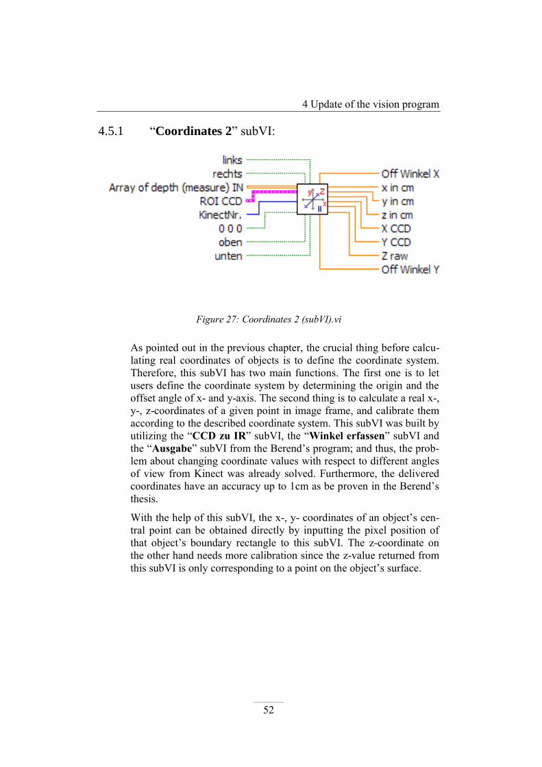
4.5.1 “Coordinates 2” subVI:
Figure 27: Coordinates 2 (subVI).vi
As pointed out in the previous chapter, the crucial thing before calcu-
lating real coordinates of objects is to define the coordinate system.
Therefore, this subVI has two main functions. The first one is to let
users define the coordinate system by determining the origin and the
offset angle of x- and y-axis. The second thing is to calculate a real x-,
y-, z-coordinates of a given point in image frame, and calibrate them
according to the described coordinate system. This subVI was built by
utilizing the “CCD zu IR” subVI, the “Winkel erfassen” subVI and
the “Ausgabe” subVI from the Berend’s program; and thus, the prob-
lem about changing coordinate values with respect to different angles
of view from Kinect was already solved. Furthermore, the delivered
coordinates have an accuracy up to 1cm as be proven in the Berend’s
thesis.
With the help of this subVI, the x-, y- coordinates of an object’s cen-
tral point can be obtained directly by inputting the pixel position of
that object’s boundary rectangle to this subVI. The z-coordinate on
the other hand needs more calibration since the z-value returned from
this subVI is only corresponding to a point on the object’s surface.

4 Update of the vision program
53
4.5.2 “Diameter” subVI:
Figure 28: Diameter (subVI).vi
In the Berend’s program, the z-coordinate of a middle point was cal-
culated by adding an offset constant to the returned z-value. The off-
set constant is an object’s radius which is measured outside the pro-
gram, and one constant is only dedicated to one specified object. The
“Diameter” subVI can perform the diameter measurement for each
detected object automatically inside the program. So there is no need
to manually input diameter constants for each object; the program is
advanced to operate that by itself. This subVI also provides an advan-
tageous to develop the learning phase later. When a diameter of an
object is know, a radius is derived easily by dividing a diameter by 2.
The diameter measurement is done by taking the width of the object’s
boundary rectangle and converting it to the appropriate value in real
life with the help of the “Coordinate 2” subVI.
4.5.3 Supporting subVIs for displaying purpose
The three dimensional coordinates of an object’s central point are now
determined. However, the program needs to mark those recognized
object on an image. To so doing, the following subVIs were brought
into the program.

4 Update of the vision program
54
“Kreuz 2” subVI:
Figure 29: Kreuz 2 (subVI).vi
The responsibility of this subVI is to place a red cross on a point
where a color template is matched. This is simply done by taking a
position of that point directly in the color matching data.
“Rectangle 2” subVI:
Figure 30: Rectangle 2 (subVI).vi
The subVI displays a boundary rectangle corresponding to each rec-
ognized object on an image by taking the information in the boundary
rectangle array output of the “Shape search 4” subVI.

4 Update of the vision program
55
“IMAQ Overlay Text” VI:
Figure 31: IMAQ Overlay Text.vi
This is an available VI in IMAQ Vision, LabVIEW. Its function is to
overlay text on an image. I use this VI to label an identified object ID
for each object on a displayed image.
5 Project summary and perspectives
56
5 Project summary and
perspectives
In this chapter the developed solution is shortly summarized. The future
perspectives and possible extensions to the created solution are proposed as
well.
5.1 Summary
The objective of this thesis is to develop a 3D robot vision system guiding a
robot arm. The program used is the update of the current robot vision system
in TI labor.
Throughout the developing process, limitations in the current vision program,
the Blind region and the change in contrast in depth image are discovered.
These can hinder and reduce the efficiency of the shape matching function in
depth image. Therefore, I created two new subVIs, namely “Distanz Modifi-
kation 2” and “To Binary”, to modify the depth map from Kinect in a more
appropriate manner and convert the depth map into binary image instead of
RGB format. Those two subVIs were able to eliminate the problems and
proven to provide better performance in shape matching function.
Following the analysis stage, a new feature of the vision program which
enabled recognition and differentiation of multiple objects via object IDs
(OID) is introduced. To achieve the task, an algorithm was developed by cus-
tomizing the general pattern recognition algorithm. The algorithm was then
implemented into the vision program by means of subroutines (subVIs). As
the result, the vision program is able to accurately recognize multiple objects
and classify them to the best matched class IDs. The updated vision program
also features a module to define the reference coordinate system with an ori-

5 Project summary and perspectives
57
gin point and x-, y-offset angles in the same manner as the current program.
Coordinates of detected objects are calculated and calibrated with respect to
the defined coordinate system.
In overall, the searching output information is relatively stable in normal
lighting condition and the objects’ coordinates are computed with sufficient
precision for the accurate operation of the robot arm.
5.2 Future perspectives
The vision program accomplished the task of detecting and classifying ob-
jects. However, the only effective criterion to differentiate objects is color
information, since shape information extracted by the available “Shape
Match Tool” VI from IMAQ Vision was found inaccurate and unreliable for
classification. Color information is an important parameter for classification,
but it solely is insufficient to differentiate objects with same color samples.
For that reason, more parameters from objects’ shape need to be taken into
account in classification.
There are various features about shape which can be extracted and calculated
from a “binary-depth” image, such as an object area, a diameter of object, a
ratio of top and bottom diameters, a ratio of two sides of a boundary rectan-
gle or a circularity factor. Some of those features are available in the pro-
gram, such as an object’s diameter or a ratio of two sides of a boundary rec-
tangle; the others such as object area or circularity factor can be obtained
with the help of IMAQ Vision VIs. However, since those features are depen-
dent on object’s distance to Kinect, in order to utilize them in classification, it
is necessary to determine relationship between those features and object’s
distance, and normalize them to the same reference distance. Furthermore,
besides the standard color matching score from “Color pattern matching”
tool, details about color information can be obtained, such as mean values of
Hue and Saturation components in a certain part of an object. Taking these
factors into account, the pattern recognition algorithm would be sophisticated
and robust to accurately differentiate objects with similar characteristics.

5 Project summary and perspectives
58
Additional issue, which could be of interest in future development, is to build
a supervised learning function for the vision program. Up till now, the vision
program can only learn a new object class by manually creating and storing
the class template in hard disk. The training phase in pattern recognition al-
gorithm needs to be done before and outside the program. A supervised
learning function allows users to instruct the program to learn and remember
a new object class. The class templates for shape and color are created auto-
matically inside the program, and are stored in hard disk for further recogni-
tion tasks. In this manner, the vision program is more intelligent and flexible,
which opens a new potential operation for the vision guided robotic system.

6 Table of Figures
59
6 Table of Figures
Figure 1: The robotic system in TI-Labor, FH Frankfurt am Main. ................................................... 9 Figure 2: Sensors and specs of Kinect camera. (Kofler, 2011) ....................................................... 11 Figure 3: Illustration of how the Xbox Kinect works. (Carmody, 2010) ......................................... 12 Figure 4: "Distanz Modifikation" subVI illustration ....................................................................... 17 Figure 5: Number of Bytes per Pixel Data (National Instruments Corporation, 2005). ................. 18 Figure 6: Illustration of three color planes in RGB image model ................................................... 18 Figure 7: Visualization of depth map is a bluish depth image in Berend's program. Foreground
and background appears in very similar color in the image, which helps an object be
extracted easily for shape recognition. ............................................................................... 19 Figure 8: Objects 2 and 3 are still in searching range, but invisible in depth image, because they
stay in the Blind region. ....................................................................................................... 21 Figure 9: Illustration of new modification method for depth map (the upper limit U of range R is
set to 1000) ......................................................................................................................... 23 Figure 10: Distanz Modifikation 2 (subVI).vi .................................................................................. 24 Figure 11: To Binary (subVI).vi ....................................................................................................... 25 Figure 12: Block diagram illustrating the testing setup ................................................................. 26 Figure 13: Matching score plot comparison - object in the Left side to Kinect ............................. 27 Figure 14: Matching score plot comparison - object in the Right side to Kinect........................... 28 Figure 15: Matching score plot comparison - object in the Center to Kinect ................................ 28 Figure 16: Processing steps of a Pattern Recognition System (Nauth, 2011). ............................... 30 Figure 17: Comparison of matching scores in RGB and depth without pre-treatment. ................ 37 Figure 18: Result of threshold in RGB model and the output rectangle........................................ 40 Figure 19: Matching result in RGB image with output rectangle from color threshold ................ 41 Figure 20: Wrong output rectangle when background changes, leading to wrong detection ...... 41 Figure 21: Kinect Initialisierung (subVI).vi ..................................................................................... 46 Figure 22: Kinect Ausgabe (subVI).vi ............................................................................................. 46 Figure 23: Shape search 4 (subVI).vi .............................................................................................. 48 Figure 24: Color search 4 (subVI).vi ............................................................................................... 49 Figure 25: Matches array processing (subVI).vi ............................................................................. 49 Figure 26: Database 2 (subVI).vi .................................................................................................... 51 Figure 27: Coordinates 2 (subVI).vi ............................................................................................... 52 Figure 28: Diameter (subVI).vi ....................................................................................................... 53 Figure 29: Kreuz 2 (subVI).vi .......................................................................................................... 54 Figure 30: Rectangle 2 (subVI).vi ................................................................................................... 54 Figure 31: IMAQ Overlay Text.vi .................................................................................................... 55
7 References
60
7 References
Berend, L. (2012). BILDVERARBEITUNGSVERFAHREN ZUR
DETEKTIERUNG UND POSITIONSBESTIMMUNG EINES
VORDEFINIERTEN OBJEKTES MIT LABVIEW. Bachelor Thesis, Frankfurt
am Main University of Applied Sciences, Frankfurt am Main.
Carmody, T. (2010, November 3). How Motion Detection Works in Xbox
Kinect. Retrieved August 1, 2012, from Wired Web site:
http://www.wired.com/gadgetlab/2010/11/tonights-release-xbox-kinect-how-
does-it-work/all/
Kofler, M. (2011). Intebriebnahme und Untersuchung des Kinect Sensors.
Master Project I, Oberoesterreich University of Applied Sciences, Wels,
Austria.
Microsoft Corporation. (2010, March 31). PrimeSense Supplies 3-D-Sensing
Technology to “Project Natal” for Xbox 360. Retrieved August 1, 2012, from
http://www.microsoft.com/en-us/news/press/2010/mar10/03-
31PrimeSensePR.aspx
Microsoft Corporation. (2009, June 1). Xbox 360 - "Project Natal" 101.
Retrieved August 1, 2012, from Microsoft Corporation Web site:
www.microsoft.com/games/en-
US/e3/pr/project%20natal%20fact%20sheet%20may%2009.rtf
MIT. (n.d.). The 50 most innovative companies 2011 - PrimeSense. Retrieved
August 1, 2012, from MIT Technology Review:
http://www.technologyreview.com/tr50/primesense/
National Instruments Corporation. (2005, January). NI Vision - IMAQ Vision
Concepts Manual.
Nauth, P. (2011). Embedded Intelligent Systems. Class Lecture, Frankfurt am
Main University of Applied Sciences, Ho Chi Minh.
Totilo, S. (2010, January 7). Natal Recognizes 31 Body Parts, Uses Tenth Of
Xbox 360 “Computing Resources”. Retrieved August 1, 2012, from

7 References
61
http://kotaku.com/5442775/natal-recognizes-31-body-parts-uses-tenth-of-
xbox-360-computing-resources
Vision Guided Robotic Systems. (n.d.). Retrieved August 8, 2012, from
Wikipedia:
http://en.wikipedia.org/wiki/Vision_Guided_Robotic_Systems#cite_ref-1
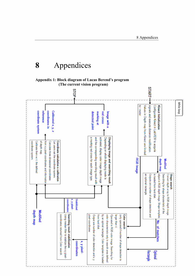
8 Appendices
62
8 Appendices
Appendix 1: Block diagram of Lucas Berend’s program
(The current vision program)

8 Appendices
63
Appendix 2: Block diagram of the updated vision program.

8 Appendices
64
Appendix 3: Front panel (User Interface) of the updated vision program

8 Appendices
65
1. Snapshot function: Take a ROI on Kinect image and store it as a picture
file in hard disk.
2. IR mode: Switch from Color image display mode to Depth image mode
Limit distance: Set a upper limit distance for a searching range and also
for displaying Depth image IR mode.
3. Matches information: Display all information of searching task, includ-
ing information of each classified object (Class ID, position), number of
matches in Color and in Shape.
4. Coordinate system calibration: Only activated when Search button is
not pressed. Allow users to set the reference coordinate system for calcu-
lation of object’s coordinates.
5. Stop: Stop running the program.
6. Search: Perform recognition and differentiation task.
7. Setting parameters for recognition and differentiation task, including
Minimum match score in color, Tolerance in Shape. Number of searched
class and Kinect number.
8. Binary depth image: Display the binary depth image
9. Kinect image: The main screen. Display Color image and Depth image
from Kinect. Marking recognized objects and labeling classified objects
when Search button is pressed.