BA S650 S850 Separator engl - bauer-vo.com S650_S850 Separator...... (carbonic acid gas CO 2,...
23
OPERATING INSTRUCTIONS for SEPARATOR S 650 and S 850 Version: January 2004
Transcript of BA S650 S850 Separator engl - bauer-vo.com S650_S850 Separator...... (carbonic acid gas CO 2,...
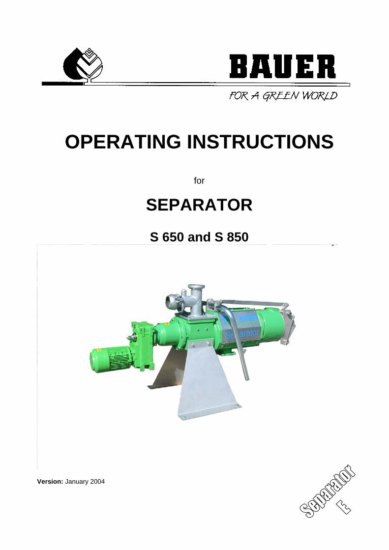
OPERATING INSTRUCTIONS
for
SEPARATOR
S 650 and S 850
Version: January 2004
Operation Manual for BAUER Separator II
INTRODUCTION
Thank you for buying a BAUER SEPARATOR!
We are happy to offer you a BAUER Separator with latest technology and top quality. This manual describes operating and maintenance of the BAUER Separator. Yet for clarity reasons and in consideration of its numerous applications it is not able to treat each thinkable case of operation or maintenance. So, if you need more information or if you are facing problems which are not mentioned in detail in this manual, please contact directly BAUER, Kowaldstraße 2, A 8570 Voitsberg/Austria. Please note that the content of this manual neither constitutes part of nor alters in any way any previous or existing agreement, promise or legal relationship. BAUER’s commitment is based solely on the respective purchase contract which also contains the complete and only valid warranty agreement. Said contractual warranty is neither extended nor limited by the content of this manual. All information contained in the present manual is based on the latest product details available at the time of printing. BAUER reserves the right to change without notice without assuming any liability! The BAUER Separator is designed for highest performance safety and reliability provided it is operated in accordance with the present operating instructions. Therefore you should study this manual thoroughly before starting your BAUER Separator! Strictly observe all instructions concerning system handling, operation and service! On this condition, the BAUER Separator will operate to your satisfaction for many years! Non-observance of this manual may cause personal injury or damage the equipment.
Please make this manual available to your staff. State the type and serial number of your BAUER Separator in all inquiries, correspondence, warranty problems, or parts orders. You find these information on the inlet housing of the separator.
We wish you a lot of success with your BAUER Separator !
This manual is to be considered an integral part of the BAUER Separator. Suppliers of separators are advised to put down in writing that they delivered the manual together with the machine.
Operation Manual for BAUER Separator III
PRODUCT DETAILS
Type description:: Separator
Type number: S 650; S 850;
Serial number:1:
Dealer:: Name:
Address:
Tel./Fax:
Date of delivery:
Producer of the device: Röhren- und Pumpenwerk BAUER Ges.m.b.H. Kowaldstr. 2 A - 8570 Voitsberg Tel.: +43 3142 200 - 0 Fax: +43 3142 200 -320/-340 e-mail: [email protected]
www.bauer-at.com
Owner or holder : Name:
Address:
Tel. / Fax: Note: Please note the type- and the serial number of your Separator and of the accessories! Be sure to state these details every time you contact your dealer
1 For every warranty claim and correspondence relating to the machine be sure to indicate the entire serial number (including all letters) of the machine and its required components. You can’t underline enough this point.
Operation Manual for BAUER Separator IV
General Safety Instructions Symbols and terms
The CE symbol that has to be affixed on the machine by the manufacturer outwardly demonstrates compliance of the machine with the directives for machines and other relevant EU directives.
This “Warning” symbol refers to important safety instructions in this manual. Whenever you see this symbol be aware of possible injury hazards. Read the note following the symbol very carefully and inform the other operators accordingly.
Non-observance of this instruction may cause damage to or destroy the
machine or individual components.
It is very important to observe this note or condition!
Qualified operators are persons who on account of their training, experience and instruction as well as their knowledge of relevant standards, rules, precautions to be taken for accident prevention, and prevailing operating conditions, have been authorized by the person in charge of plant safety to perform the respective tasks required, and in doing so are able to recognize and avoid potential hazards. Among other things, knowledge of first-aid procedures is also required.
Product liability As defined by the product liability law every farmer is also an entrepreneur! According to §9 PHG (Product Liability Law), liability for damage to corporeal things caused by defective products is expressly excluded. This exclusion of liability also applies to parts not manufactured by BAUER itself but purchased from external suppliers.
Duty to furnish information Even if the customer passes on the machine later-on he is obliged to hand the operating manual on to the new receiver, too. The receiver of the machine must be instructed with reference to the mentioned regulations.
Intended use • The BAUER Separator is built exclusively for normal agricultural applications (intended use). • Any use beyond this normal use is considered non-conforming. Manufacturer is not liable for damage resulting from such non-conforming use, the sole liability for damage from non-conforming use is with the user. • Intended use also includes compliance with the manufacturer’s operating, maintenance and service instructions. • The BAUER Separator may be used and operated only by persons who are familiar with the device and aware of the hazards involved. • All rules for accident prevention as well as any other generally valid specifications and regulations relating to safety, work medicine and traffic law must be strictly observed. • Unauthorized modifications on the machine release the manufacturer from liability for damage resulting thereof.
WARNING!
CAUTION
NOTE
Operation Manual for BAUER Separator V
INDEX 1 GENERAL INSTRUCTIONS FOR SAFETY AND ACCIDENT PREVENTION ...........................................1
2 GENERAL......................................................................................................................................................1 2.2 Handling of slurry ....................................................................................................................................1 2.3 Proper Use ..............................................................................................................................................1
3 FUNCTIONAL DESCRIPTION ......................................................................................................................2
4 SEPARATOR INSTALLATION .....................................................................................................................3 4.1 Installation scheme .................................................................................................................................3 4.2 Delivery scope.........................................................................................................................................3 4.3 Required tools .........................................................................................................................................3 4.3 Installation and mounting ........................................................................................................................3
5 PREPARATIONS FOR THE START-UP.......................................................................................................5
6 START-UP .....................................................................................................................................................5 6.1 Setting instructions..................................................................................................................................5
6.1.1 Building up of the plug .....................................................................................................................6 6.1.2 Settings for stabilizing the plug ........................................................................................................6
6.2 Further instructions for trouble-free operation: .......................................................................................7 7 MALFUNCTION – REMEDY..........................................................................................................................8
8 PUTTING OUT OF OPERATION ..................................................................................................................9
9 SHUT-DOWN .................................................................................................................................................9
10 DISASSEMBLY – ASSEMBLY..................................................................................................................9 10.1 Disassembly ........................................................................................................................................9 10.2 Assembly ...........................................................................................................................................10
11 MAINTENANCE .......................................................................................................................................11
12 STORAGE ................................................................................................................................................12 12.1 Short-term storage.............................................................................................................................12 12.2 Long-term storage .............................................................................................................................12
13 TECHNICAL DATA..................................................................................................................................12 13.1 Technical data of separator...............................................................................................................12 13.2 Type plates ........................................................................................................................................12
13.2.1 Separator .......................................................................................................................................12 13.2.2 Gearbox .........................................................................................................................................13 13.2.3 Motor ..............................................................................................................................................13
13.3 Decal information...............................................................................................................................14 14 SUMMARY OF STRUCTURAL COMPONENTS ....................................................................................14
14.1 Gearbox and motor............................................................................................................................14 15 SPARE AND WEAR PARTS ...................................................................................................................14
16 ACCESSORIES........................................................................................................................................14 16.1 Separator control with reverse control ..............................................................................................14
17 CONFORMITY CERTIFICATE.................................................................................................................18
Operation Manual for BAUER Separator 1
1 GENERAL INSTRUCTIONS FOR SAFETY AND ACCIDENT PREVENTION
Check the operational safety of the machine before every start-up. 1. In addition to the instructions contained in this manual, all specifications generally valid for safety and
accident prevention must be observed! 2. The warning and instruction signs affixed to the machine give very important instructions for safe
operation. Observing them serves your own personal safety! 3. Never put the machine into operation unless all guards and safety devices are completely mounted and
in their proper working position! 4. Acquaint yourself with all equipment components and controls as well as their respective functions
before starting to work. It is too late when the device is already running! 5. The operator’s clothes should fit tightly. Avoid wearing loose clothes! 6. When handling slurry always keep in mind that the gasses produced are highly toxic and extremely
explosive in combination with oxygen. Therefore, open fires, light tests, sparking and smoking are strictly forbidden!
7. Utmost care is required with regard to gasses in slurry and dung channels at open valves to the preliminary pit, before the main pit, or at cross channels. The same applies to mixing and withdrawal points when mixers or pumps are running!
8. When handling slurry always ensure sufficient ventilation! 9. Keep the machine clean to avoid fire hazards! Maintenance 1. Never perform any maintenance, service or cleaning work or fault elimination steps unless the drive is
turned off and the engine is standing still! 2. Check proper fit of all nuts and bolts regularly and tighten them, if necessary. 3. If maintenance work is required on the lifted machine always secure it by means of appropriate
supports! 4. When exchanging tools with cutting edges always use proper tools and wear safe protective gloves. 5. Dispose of oil, grease and filters according to local laws and regulations! 6. Always turn off power before working on the electric system! 7. Spare parts must meet manufacturer’s minimum technical specifications! This is the case for instance
with original spare parts for instance! 2 GENERAL
2.2 Handling of slurry Apart from the dangers resulting from moving or pressurized parts the operation of
slurry treating machines may be hazardous because of liquid manure gases. These gases (carbonic acid gas CO2, ammonia gas NH3, hydrogen sulfide H2S, methane CH4) can cause intoxications and explosions. When operating mixers, agitators, intertank transfer systems, agitating lances and slurry aeration systems make sure to exclude the inflow of gases into the stable (provide siphons or gate valves). When handling slurry inside the stable take care of good forced ventilation.
2.3 Proper Use The BAUER separator splits pumpable slurry (which must be free of foreign objects like metal parts, stones, pieces of wood or cloth) into a solid and a liquid fraction. The BAUER separator is designed for continuous open air operating within a temperature range of 0°C to 40°C. In case of high air humidity (for example in coastal areas) or under extreme solar radiation special designs of gear and motor will be necessary. For further details please contact the manufacturer. When chosing the required delivery pump please observe that the separator is operating in unpressurized mode.
CAUTION!
Operation Manual for BAUER Separator 2
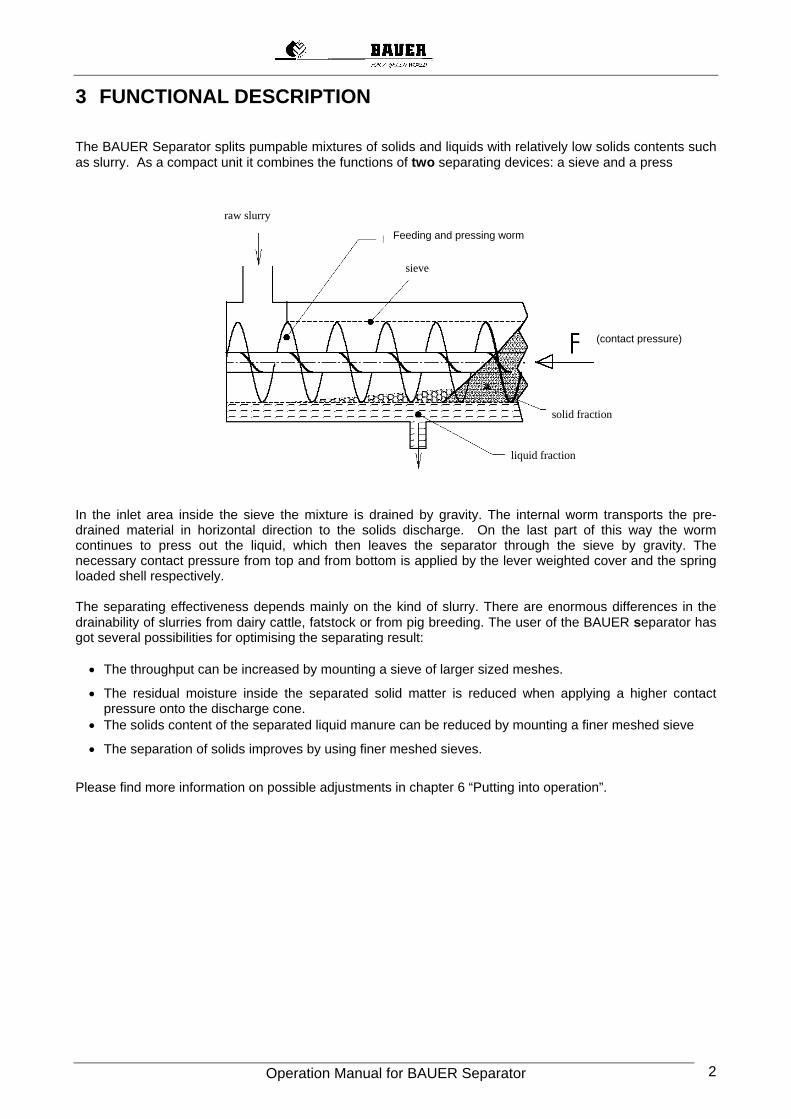
3 FUNCTIONAL DESCRIPTION The BAUER Separator splits pumpable mixtures of solids and liquids with relatively low solids contents such as slurry. As a compact unit it combines the functions of two separating devices: a sieve and a press In the inlet area inside the sieve the mixture is drained by gravity. The internal worm transports the pre-drained material in horizontal direction to the solids discharge. On the last part of this way the worm continues to press out the liquid, which then leaves the separator through the sieve by gravity. The necessary contact pressure from top and from bottom is applied by the lever weighted cover and the spring loaded shell respectively. The separating effectiveness depends mainly on the kind of slurry. There are enormous differences in the drainability of slurries from dairy cattle, fatstock or from pig breeding. The user of the BAUER separator has got several possibilities for optimising the separating result:
• The throughput can be increased by mounting a sieve of larger sized meshes.
• The residual moisture inside the separated solid matter is reduced when applying a higher contact pressure onto the discharge cone.
• The solids content of the separated liquid manure can be reduced by mounting a finer meshed sieve
• The separation of solids improves by using finer meshed sieves.
Please find more information on possible adjustments in chapter 6 “Putting into operation”.
raw slurry
feed- and press srew
sieve
solid fraction
liquid fraction
force(contact pressure)
Feeding and pressing worm
Operation Manual for BAUER Separator 3
4 SEPARATOR INSTALLATION
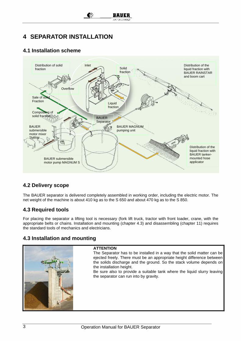
4.1 Installation scheme
4.2 Delivery scope The BAUER separator is delivered completely assembled in working order, including the electric motor. The net weight of the machine is about 410 kg as to the S 650 and about 470 kg as to the S 850. 4.3 Required tools For placing the separator a lifting tool is necessary (fork lift truck, tractor with front loader, crane, with the appropriate belts or chains. Installation and mounting (chapter 4.3) and disassembling (chapter 11) requires the standard tools of mechanics and electricians. 4.3 Installation and mounting
ATTENTION The Separator has to be installed in a way that the solid matter can be ejected freely. There must be an appropriate height difference between the solids discharge and the ground. So the stack volume depends on the installation height. Be sure also to provide a suitable tank where the liquid slurry leaving the separator can run into by gravity.
Distribution of solid fraction
Sale of solid Fraction Composting of solid fraction BAUER
SeparatorBAUER MAGNUM pumping unit
Distribution of the liquid fraction with BAUER tanker-mounted hose applicator
Distribution of the liquid fraction with BAUER RAINSTAR and boom cart
BAUER submersible motor pump MAGNUM S
BAUER submersible motor mixer TMRW
Inlet Solid fraction
Liquid fraction
Overflow
Operation Manual for BAUER Separator 4
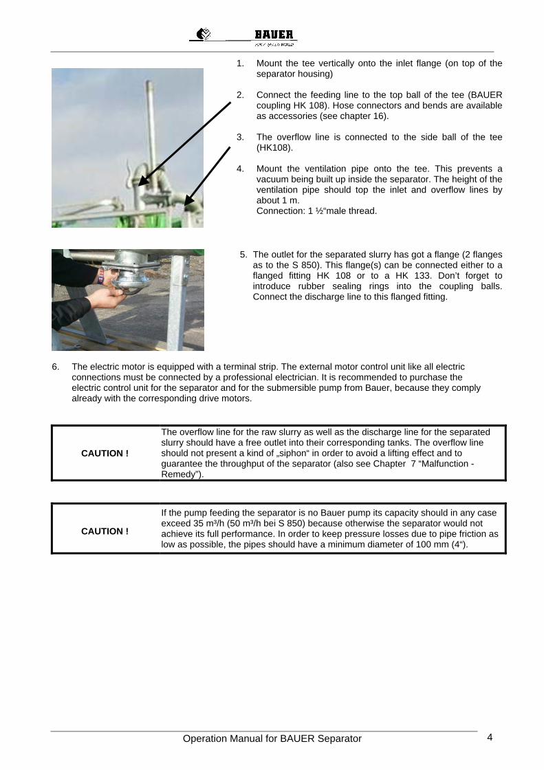
1. Mount the tee vertically onto the inlet flange (on top of the separator housing)
2. Connect the feeding line to the top ball of the tee (BAUER
coupling HK 108). Hose connectors and bends are available as accessories (see chapter 16).
3. The overflow line is connected to the side ball of the tee
(HK108). 4. Mount the ventilation pipe onto the tee. This prevents a
vacuum being built up inside the separator. The height of the ventilation pipe should top the inlet and overflow lines by about 1 m. Connection: 1 ½“male thread.
5. The outlet for the separated slurry has got a flange (2 flanges as to the S 850). This flange(s) can be connected either to a flanged fitting HK 108 or to a HK 133. Don’t forget to introduce rubber sealing rings into the coupling balls. Connect the discharge line to this flanged fitting.
6. The electric motor is equipped with a terminal strip. The external motor control unit like all electric
connections must be connected by a professional electrician. It is recommended to purchase the electric control unit for the separator and for the submersible pump from Bauer, because they comply already with the corresponding drive motors.
CAUTION !
The overflow line for the raw slurry as well as the discharge line for the separated slurry should have a free outlet into their corresponding tanks. The overflow line should not present a kind of „siphon“ in order to avoid a lifting effect and to guarantee the throughput of the separator (also see Chapter 7 “Malfunction - Remedy”).
CAUTION !
If the pump feeding the separator is no Bauer pump its capacity should in any case exceed 35 m³/h (50 m³/h bei S 850) because otherwise the separator would not achieve its full performance. In order to keep pressure losses due to pipe friction as low as possible, the pipes should have a minimum diameter of 100 mm (4“).
Operation Manual for BAUER Separator 5
5 PREPARATIONS FOR THE START-UP • Check oil level of gear box, fill up if necessary. Dispose of used oil properly. Find details in chapter
14 „Summary of structural components“, gear box. • Check connection and tightness of feeding line between pump and separator; connection and
tightness of overflow line; free run-off into collecting tank; connection and tightness of line for run-off of separated slurry
• Set motor protection at required rated voltage (see also chapter 14); check correct direction of rotation following the arrow on the housing and on the motor; shut off the motor again.
• Take away the weights (minimum locking pressure)
Make sure that no coarse foreign objects like metal parts, stones, pieces of wood or
cloth can get into the separator for not overstraining especially sieve and worm. Furthermore, be aware that abrasive substances (for instance high portion of sand) will shorten the lifetime of the machine.
6 START-UP
In order to achieve satisfactory separation results, it is necessary to mix the slurry before starting the separation procedure.
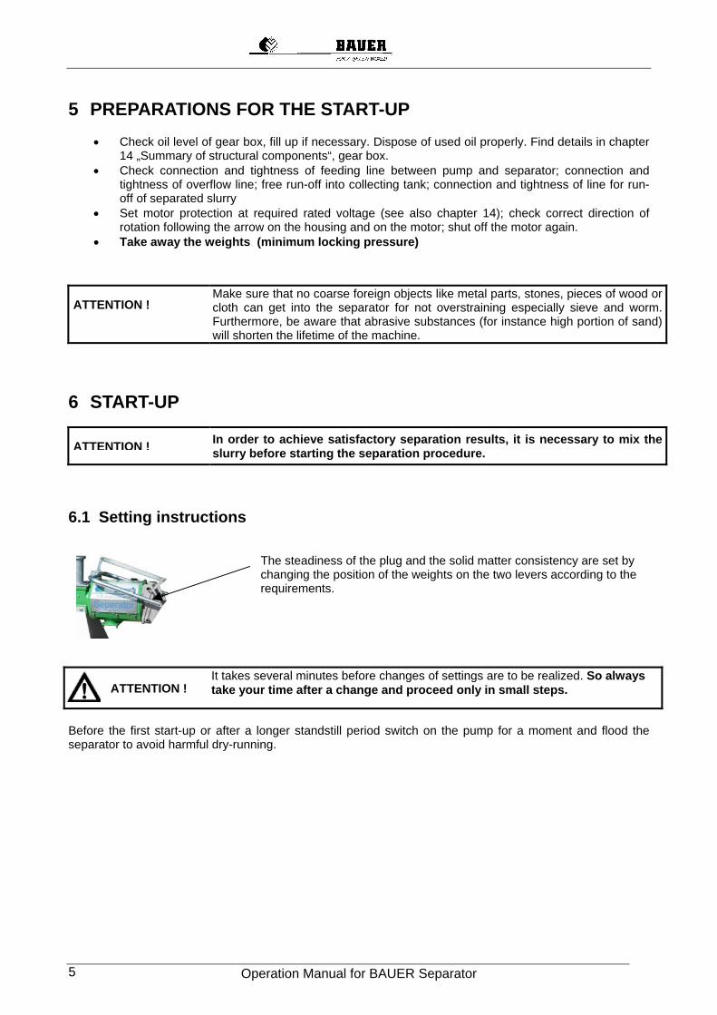
6.1 Setting instructions
The steadiness of the plug and the solid matter consistency are set by changing the position of the weights on the two levers according to the requirements.
It takes several minutes before changes of settings are to be realized. So always
take your time after a change and proceed only in small steps.
Before the first start-up or after a longer standstill period switch on the pump for a moment and flood the separator to avoid harmful dry-running.
ATTENTION !
ATTENTION !
ATTENTION !
Operation Manual for BAUER Separator 6
6.1.1 Building up of the plug
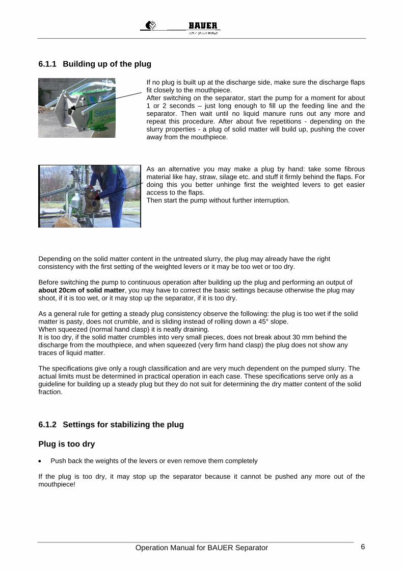
If no plug is built up at the discharge side, make sure the discharge flaps fit closely to the mouthpiece. After switching on the separator, start the pump for a moment for about 1 or 2 seconds – just long enough to fill up the feeding line and the separator. Then wait until no liquid manure runs out any more and repeat this procedure. After about five repetitions - depending on the slurry properties - a plug of solid matter will build up, pushing the cover away from the mouthpiece.
As an alternative you may make a plug by hand: take some fibrous material like hay, straw, silage etc. and stuff it firmly behind the flaps. For doing this you better unhinge first the weighted levers to get easier access to the flaps. Then start the pump without further interruption.
Depending on the solid matter content in the untreated slurry, the plug may already have the right consistency with the first setting of the weighted levers or it may be too wet or too dry. Before switching the pump to continuous operation after building up the plug and performing an output of about 20cm of solid matter, you may have to correct the basic settings because otherwise the plug may shoot, if it is too wet, or it may stop up the separator, if it is too dry. As a general rule for getting a steady plug consistency observe the following: the plug is too wet if the solid matter is pasty, does not crumble, and is sliding instead of rolling down a 45° slope. When squeezed (normal hand clasp) it is neatly draining. It is too dry, if the solid matter crumbles into very small pieces, does not break about 30 mm behind the discharge from the mouthpiece, and when squeezed (very firm hand clasp) the plug does not show any traces of liquid matter. The specifications give only a rough classification and are very much dependent on the pumped slurry. The actual limits must be determined in practical operation in each case. These specifications serve only as a guideline for building up a steady plug but they do not suit for determining the dry matter content of the solid fraction.
6.1.2 Settings for stabilizing the plug Plug is too dry • Push back the weights of the levers or even remove them completely If the plug is too dry, it may stop up the separator because it cannot be pushed any more out of the mouthpiece!
Operation Manual for BAUER Separator 7
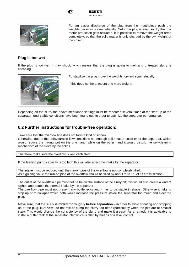
For an easier discharge of the plug from the mouthpiece push the weights backwards symmetrically. Yet if the plug is even so dry that the motor protection gets actuated, it is possible to remove the weight arms completely, so that the solid matter is only charged by the own weight of the cover.
Plug is too wet If the plug is too wet, it may shoot, which means that the plug is going to melt and untreated slurry is escaping.
To stabilize the plug move the weights forward symmetrically. If this does not help, mount one more weight.
Depending on the slurry the above mentioned settings must be repeated several times at the start-up of the separator, until stable conditions have been found out, in order to optimize the separator performance. 6.2 Further instructions for trouble-free operation: Take care that the overflow line does not form a kind of siphon. Otherwise, due to the unfavourable flow conditions not enough solid matter could enter the separator, which would reduce the throughput on the one hand, while on the other hand it would disturb the self-cleaning mechanism of the sieve by the solids. Therefore make sure the overflow is well ventilated! If the feeding pump capacity is too high this will also affect the intake by the separator. The intake must be reduced until the run-off pipe of the overflow is not completely filled. As a guiding value the run-off pipe of the overflow should be filled by about ½ to 1/3 of its cross section! The outlet of the overflow pipe must not be below the surface of the slurry pit; this would also create a kind of siphon and trouble the normal intake by the separator. The overflow pipe must not present any bottlenecks and it has to be stable in shape. Otherwise it risks to stop up or to collapse which both would increase the pressure inside the separator too much and eject the plug. Make sure, that the slurry is mixed thoroughly before separation – in order to avoid shooting and stopping up of the plug. But note: do not mix or pump the slurry too often (particularly when the pits are of smaller size). This would change the consistency of the slurry and make it greasy. As a remedy it is advisable to install a buffer tank at the separator inlet which is filled by means of a level control.
Operation Manual for BAUER Separator 8
7 MALFUNCTION – REMEDY
Malfunction Cause Remedy
Check motor protection for proper setting, if necessary adjust it to maximum value according to table 13.2.3
Overload Plug too dry
See setting instructions – 6.1
Separator stops
Foreign object blocks up the worm
Check Separator inlet, remove foreign object; check worm and sieve.
Intake too low Check the pump (direction of rotation) Check feeding line Mount vent valve/pipe onto tee of separator
Lifting effect inside overflow line, slurry is sucked out of the Separator. Reduce intake so that overflow pipe is only
half filled at max. Make sure the overflow can run out freely.
Sieve clogged Clean the sieve through side shields or if necessary disassemble for cleaning. Activate reverse control – See 16.1
Worm or sieve worn out Check worm diameter, replace the worm if necessary, check sieve wear and replace it, if required.
Sieve is worn out only in places, wrong setting of sieve guiding
Check obstruction or soiling of sieve guiding
Low output of solid and liquid fraction
Slurry mixed or pumped too often (squelched)
Install buffer tank at the separator inlet see: 6.2
Solid output too low, plug is too dry
Weights too near to the front. See setting instructions – 6.1.
Wrong direction of rotation of separator
Check electrical connections No solid output, minimum liquid discharge
Worm channel stopped up Check and clean the worm See Disassembly – 10.1.
Increased worm and sieve wear Abrasive components in the slurry (sand)
Let abrasive components settle as far as possible before separation.
Moisture content of the discharged solid matter varies considerably
Different consistency of raw slurry
Mix and homogenise slurry thoroughly.
Solid matter content in raw slurry is too low. Weights pushed back too far.
Mix and homogenise the medium (slurry) properly See setting instructions 6.1.
Plug is melting and liquid runs out of the mouthpiece
Solid matter is too fine and has got no fibrous structure
Use a finer sieve
Operation Manual for BAUER Separator 9
8 PUTTING OUT OF OPERATION 1. Switch off the feeding pump of the separator 2. Switch off the separator.
If the separator is going to stay out of operation for several days, first keep it running for one or two more minutes and switch it off but then. Depending on the kind of treated slurry, the separator may be out of operation for a week or even longer without that the plug will have to be remouved.
3. For longer standstills remove the plug and clean the separator. Withdraw the cover and clear away the plug by hand.
4. If the separator is going to be used at temperatures below zero, be sure to drain completely all inlet and return pipes as well as the separator itself after finishing the separation in order to avoid slurry freezing inside the machine. If the plug has firmly frozen in the separator melt it with hot water before putting the separator into operation again.
9 SHUT-DOWN If your BAUER-Separator will not be used for a longer time put it out of operation according to chapter 8 and clean it according to chapter 10 “Disassembly”. Store the machine as described in chapter 13 “Storage”. If the machine needs to be scrapped it is absolutely necessary to dispose of gear oil and electrical/electronic components as hazardous waste. The metal parts can be recycled..
10 DISASSEMBLY – ASSEMBLY
10.1 Disassembly It is necessary to disassemble the separator for • cleaning of sieve and worm • replacing sieve and worm • removing foreign objects in case of separator blockage • removing dried solid matter which is sticking on the worm after a longer standstill thus making the
delivery of solid matter impossible. For this purpose put the machine out of operation according to chapter 8. Then disassemble it as described below.
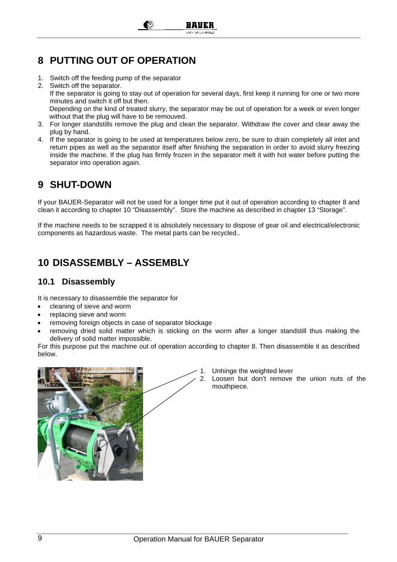
1. Unhinge the weighted lever 2. Loosen but don’t remove the union nuts of the
mouthpiece.
Operation Manual for BAUER Separator 10
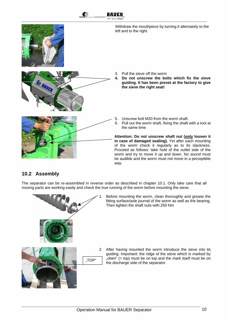
Withdraw the mouthpiece by turning it alternately to the left and to the right.
3. Pull the sieve off the worm 4. Do not unscrew the bolts which fix the sieve
guiding. It has been preset at the factory to give the sieve the right seat!
5. Unscrew bolt M20 from the worm shaft. 6. Pull out the worm shaft, fixing the shaft with a tool at
the same time Attention: Do not unscrew shaft nut (only loosen it in case of damaged sealing). Yet after each mounting of the worm check it regularly as to its slackness. Proceed as follows: take hold of the outlet side of the worm and try to move it up and down. No sound must be audible and the worm must not move in a perceptible way.
10.2 Assembly The separator can be re-assembled in reverse order as described in chapter 10.1. Only take care that all moving parts are working easily and check the true running of the worm before mounting the sieve.
1. Before mounting the worm, clean thoroughly and grease the fitting surface/axle journal of the worm as well as the bearing. Then tighten the shaft nuts with.250 Nm
2. After having mounted the worm introduce the sieve into its guiding. Important: the ridge of the sieve which is marked by „oben“ (= top) must be on top and the mark itself must be on the discharge side of the separator.
„TOP“
Operation Manual for BAUER Separator 11
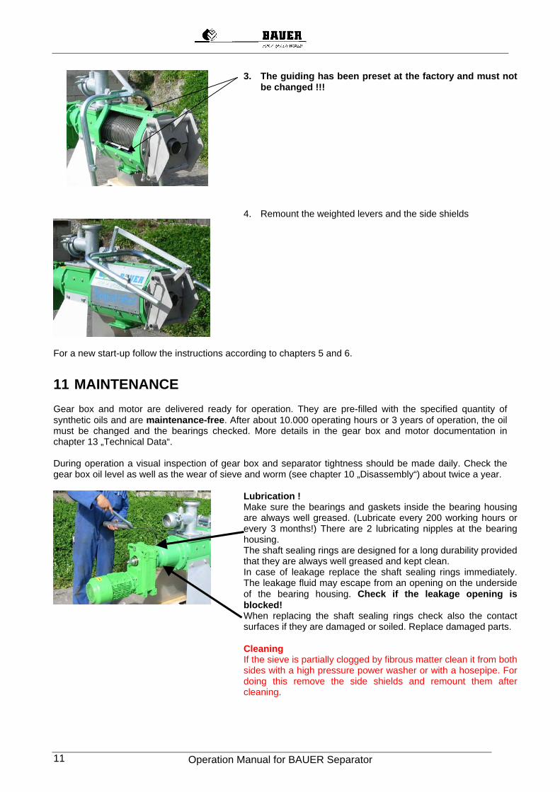
3. The guiding has been preset at the factory and must not be changed !!!
4. Remount the weighted levers and the side shields
For a new start-up follow the instructions according to chapters 5 and 6.
11 MAINTENANCE Gear box and motor are delivered ready for operation. They are pre-filled with the specified quantity of synthetic oils and are maintenance-free. After about 10.000 operating hours or 3 years of operation, the oil must be changed and the bearings checked. More details in the gear box and motor documentation in chapter 13 „Technical Data“. During operation a visual inspection of gear box and separator tightness should be made daily. Check the gear box oil level as well as the wear of sieve and worm (see chapter 10 „Disassembly“) about twice a year.
Lubrication ! Make sure the bearings and gaskets inside the bearing housing are always well greased. (Lubricate every 200 working hours or every 3 months!) There are 2 lubricating nipples at the bearing housing. The shaft sealing rings are designed for a long durability provided that they are always well greased and kept clean. In case of leakage replace the shaft sealing rings immediately. The leakage fluid may escape from an opening on the underside of the bearing housing. Check if the leakage opening is blocked! When replacing the shaft sealing rings check also the contact surfaces if they are damaged or soiled. Replace damaged parts.
Cleaning
If the sieve is partially clogged by fibrous matter clean it from both sides with a high pressure power washer or with a hosepipe. For doing this remove the side shields and remount them after cleaning.
Operation Manual for BAUER Separator 12
12 STORAGE 12.1 Short-term storage For a short-term storage (up to three months) the BAUER Separator has to be stored in a closed and dry shelter. Protect the sealing rings of the gear motor from direct UV-radiation (disassembled motor). 12.2 Long-term storage For a long-term storage (more than 3 months) the BAUER Separator has to be stored in a closed and dry shelter. Protect the sealing rings of the gear motor from direct UV-radiation (disassembled motor). Change the gear oil against anti-corrosion oil (Castrol 488/79 or equivalent); dispose of the used oil properly. This above mentioned anti-corrosion oil can be mixed with the lubricant indicated on the type plate fixed onto the gearbox. So it is not necessary to empty and rinse the gearbox before re-filling. Under the condition of proper storage the corrosion inhibition remains active for at least 12 months. All outside blank metal surfaces must be protected by two layers of a corrosion inhibitor (Tectyl 506 or equivalent).
13 TECHNICAL DATA
13.1 Technical data of separator
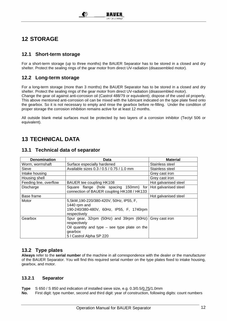
Denomination Data Material Worm, wormshaft Surface especially hardened Stainless steel Sieve Available sizes 0.3 / 0.5 / 0.75 / 1.0 mm Stainless steel Intake housing Grey cast iron Housing shell Grey cast iron Feeding line, overflow BAUER tee coupling HK108 Hot galvanised steel Discharge Square flange (hole spacing 150mm) for
connection of BAUER coupling HK108 / HK133Hot galvanised steel
Base frame Hot galvanised steel Motor 5,5kW,190-220/380-420V, 50Hz, IP55, F,
1440 rpm and 190-240/380-480V, 60Hz, IP55, F, 1740rpm respectively
Gearbox Spur gear, 32rpm (50Hz) and 39rpm (60Hz) respectively Oil quantity and type – see type plate on the gearbox 5 l Castrol Alpha SP 220
Grey cast iron
13.2 Type plates Always refer to the serial number of the machine in all correspondence with the dealer or the manufacturer of the BAUER Separator. You will find this required serial number on the type plates fixed to intake housing, gearbox, and motor.
13.2.1 Separator Type S 650 / S 850 and indication of installed sieve size, e.g. 0.3/0.5/0.75/1.0mm No. First digit: type number, second and third digit: year of construction, following digits: count numbers
Operation Manual for BAUER Separator 13
13.2.2 Gearbox Quantity and specification of filled gear oil Type gear oil (e.g. FUA 75A) No. serial number of gear kW power of gear min-1 worm rotation per minute Nm gear torque H50 design geared motor(see chapter 15.2)
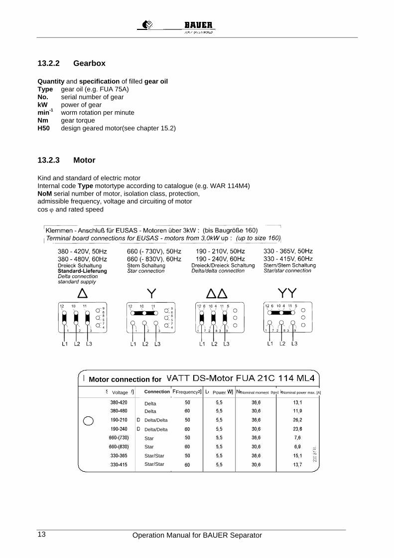
13.2.3 Motor Kind and standard of electric motor Internal code Type motortype according to catalogue (e.g. WAR 114M4) NoM serial number of motor, isolation class, protection, admissible frequency, voltage and circuiting of motor cos ϕ and rated speed
Delta Delta
Delta/Delta
Delta/Delta
Star
Star
Star/Star
Star/Star
Connection
Motor connection for Voltage Frequency Power Nominal moment [Nm] Nominal power max. [A]
Operation Manual for BAUER Separator 14
13.3 Decal information The following decal information are affixed to the BAUER Separator:;
• Arrow on electric motor: indicates proper direction of rotation.
• Arrow on housing shell: indicates proper direction of rotation of screw shaft.
• Yellow textbox on housing shell: reminds of hazards in slurry handling.
Decals must be replaced immediately when they are damaged. They can be ordered from your retailer. As to the part numbers please see the lists of spare and wearing parts (chapter 15).
14 SUMMARY OF STRUCTURAL COMPONENTS
14.1 Gearbox and motor
15 SPARE AND WEAR PARTS See extra spare parts list
16 ACCESSORIES
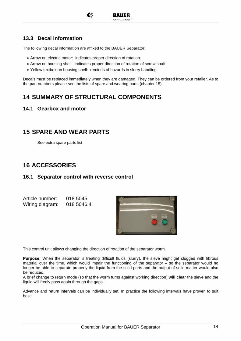
16.1 Separator control with reverse control Article number: 018 5045 Wiring diagram: 018 5046.4
This control unit allows changing the direction of rotation of the separator worm. Purpose: When the separator is treating difficult fluids (slurry), the sieve might get clogged with fibrous material over the time, which would impair the functioning of the separator – so the separator would no longer be able to separate properly the liquid from the solid parts and the output of solid matter would also be reduced. A brief change to return mode (so that the worm turns against working direction) will clear the sieve and the liquid will freely pass again through the gaps. Advance and return intervals can be individually set. In practice the following intervals have proven to suit best:
Operation Manual for BAUER Separator 15
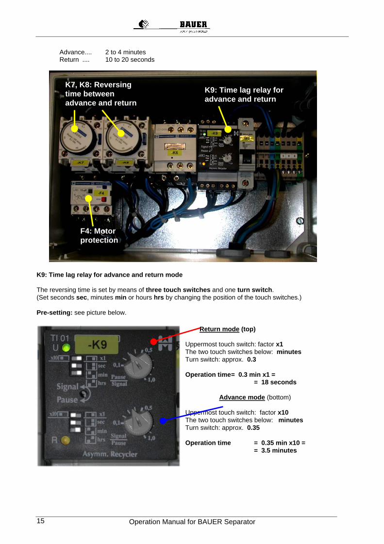
Advance.... 2 to 4 minutes Return .... 10 to 20 seconds
K9: Time lag relay for advance and return mode The reversing time is set by means of three touch switches and one turn switch. (Set seconds sec, minutes min or hours hrs by changing the position of the touch switches.) Pre-setting: see picture below.
Return mode (top) Uppermost touch switch: factor x1 The two touch switches below: minutes Turn switch: approx. 0.3 Operation time = 0.3 min x1 = = 18 seconds Advance mode (bottom) Uppermost touch switch: factor x10 The two touch switches below: minutes Turn switch: approx. 0.35 Operation time = 0.35 min x10 = = 3.5 minutes
K7, K8: Reversing time between advance and return
F4: Motor protection
K9: Time lag relay for advance and return
Operation Manual for BAUER Separator 16
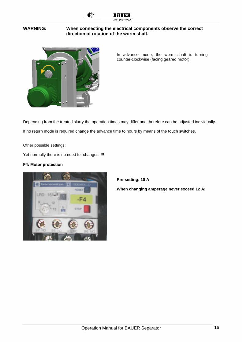
WARNING: When connecting the electrical components observe the correct direction of rotation of the worm shaft.
In advance mode, the worm shaft is turning counter-clockwise (facing geared motor)
Depending from the treated slurry the operation times may differ and therefore can be adjusted individually. If no return mode is required change the advance time to hours by means of the touch switches. Other possible settings: Yet normally there is no need for changes !!!! F4: Motor protection
Pre-setting: 10 A When changing amperage never exceed 12 A!
Operation Manual for BAUER Separator 17
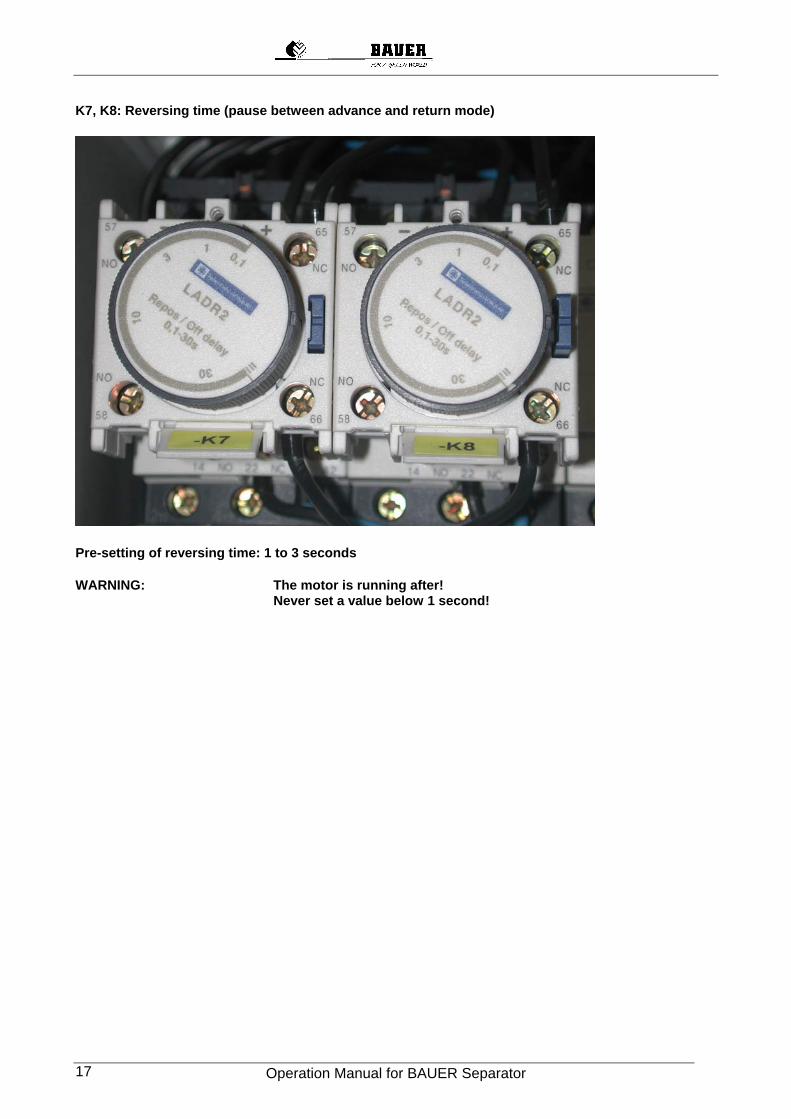
K7, K8: Reversing time (pause between advance and return mode)
Pre-setting of reversing time: 1 to 3 seconds WARNING: The motor is running after! Never set a value below 1 second!
Operation Manual for BAUER Separator 18
17 CONFORMITY CERTIFICATE
EU Declaration of Conformity
in accordance with the General EU Practices for Machinery 89/392/EWG, Annex II A We,
Röhren- und Pumpenwerk BAUER Gesellschaft m.b.H.
Kowaldstraße 2, A - 8570 Voitsberg - Austria Tel. +43 3142 200 - 0, Telefax: +43 3142 200 -320/-340
herewith declare that in respect of its conception and design and in the types and styles which we market the machine mentioned below fully corresponds with the relevant fundamental provisions for safety and health stipulated in the General EU Practices for machinery. This declaration becomes null and void should any modification be made on the machine without our prior consent
Designation: BAUER SEPARATOR Basic models: S 650 / S 850
This range of machines has been developed and manufactured according to the standard:
EN 809
which also contains normative reference to
EN 292-1 - 1991, EN 292-2 – 1991 and EN 294 – 1992.
Technical director
Voitsberg, 01.09.2003