AIRCRAFT GENERAL B747-200 General Aircraft Descriptions and Limitations 1.

KU
F B747
V12-
24 k
V
Instruction for Assembly,
Operation and Maintenance of
DRIESCHER Indoor
Vacuum Circuit-Breakers
• Rated voltage 12 kV up to 38,5 kV
• Rated current 630 A up to 2500 A
ELEKTROTECHNISCHE WERKEFRITZ DRIESCHER & SÖHNE GMBHD-85366 MOOSBURG • TEL. +49 87 61 6 81-0 • FAX +49 87 61 68 12 30http://www.driescher.com [email protected]
2
Operating Conditions
After receipt of delivery, please unpack switchcarefully and check for possible transportation damages. If damages have occurred, please immediatelyinform us and the carrier. After unpacking pleaseclean the switches and accessory from any contami
nation from the packing material and protect themfrom damages, humidity and pollution until installation. For transportation only use the frame, never thevacuum poles.
The switches are designed for normal operating conditions acc. to EN 622711, Class "Minus 5 Indoor”. Aproper functioning is also guaranteed up to temperatures of up to 15°C. The maximum value of theambient temperature is 40°C; the average value over24 hours is max. 35°C.The values of the insulating power are – acc. to EN622711 – are related to sea level.
For altitudes up to 1000 m any reduction in insulationcaused by the reduced insulating power of the air isinsignificant and can be ignored. For an installationabove 1000 m sea level it is necessary to correct thevalues given for the rated powerfrequency withstandvoltage and the rated lightning impulse withstand voltage.
DRIESCHER - Indoor Vacuum Circuit-Breakers
Contents:
• 2 Transportation and storage, operating conditions
• 3 Technical date
• 4 Terminal zones, weights
• 5 Assembly, interlocking
• 6 Auxiliary switches, releases
• 7 Illustration of releases, motor actuators
• 8 Design and operating mode of the vacuum circuitbreaker
• 9 Putting into service and operation of the vacuum circuitbreaker
• 10 Maintenance
• 12 Range of production
Transportation and Storage
B747
General notes
These operating and maintenance instructions must
always be kept at the place of installation and must be
available to operating personnel at all times.
The operating and maintenance personnel must have
read and understood these instructions prior to the
commencement of any work.
Correct transport, storage, installation and assembly,
as well as careful operating and commissioning are
essential to ensure the satisfactory and safe operati-
on of these switchgears.
Guarantee
Driescher shall not accept any liability for damage
which is based on incorrect use, incorrect implemen-
tation of work or work carried out by non-trained per-
sons, or third party liability.
Warning
During the operation of these electrical switchgears
some parts are inevitably under hazardous voltage
and mechanical parts, also those remotely controlled,
may move fast.
Non-observance of the warning signs can lead to
severe injury or damage to property.
Only appropriately qualified personnel, as specified in
the VDE 0105 (trained electricians) are to work on this
equipment or in the vicinity thereof.
These persons must have a sound knowledge of all
general regulations; VDE/IEC specifications, 5 rules
on safety in compliance with VDE, safety regulations,
accident prevention regulations as well as all war-
nings and maintenance measures given in these
instructions.
3
B747
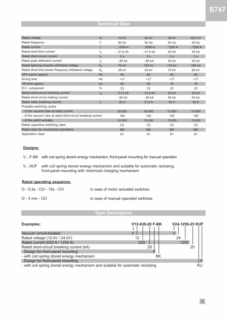
Technical Data
Type Description
Examples: V12-630-20 F-BK V24-1250-25 KUF
Vacuum circuitbreaker V VRated voltage (12 kV / 24 kV) 12 24Rated current (630 A / 1250 A) 630 1250 Rated shortcircuit breaking current (kA) 20 25
Design for frontpanel mounting F with coil spring stored energy mechanism BK
Design for frontpanel mounting F with coil spring stored energy mechanism and suitable for automatic reclosing KU
Designs:
V....FBK with coil spring stored energy mechanism, frontpanel mounting for manual operation
V....KUF with coil spring stored energy mechanism and suitable for automatic reclosing,frontpanel mounting with motorized charging mechanism
O 0,3s CO 15s CO in case of motor actuated switches
O 3 min CO in case of manual operated switches
Rated operating sequence:
Rated voltage
Rated frequency
Rated current
Rated shorttime current
Rated shortcircuit current
Rated peak withstand current
Rated lightning impulse withstand voltage
Rated shorttime power frequency withstand voltage
OFFperiod approx.
Arcing time
ONtime approx.
D.C. component
Rated shortcircuit breaking current
Rated shortcircuit making current
Rated cable breaking current
Possible switching cycles
of the vacuum tube at rated current
of the vacuum tube at rated shortcircuit breaking current
of the switch actuator
Rated capacitive switching class
Rated class for mechanical operations
Application class
Ur
frIrIktkIpUp
Ud
ms
ms
ms
%
Isc
Ic
12 kV
50 Hz
... 2500 A
...31,5 kA
3 s
...80 kA
75 kV
28 kV
65
<17
60
23
...31,5 kA
...80 kA
25 A
30.000
100
10.000
C2
M2
S1
24 kV
50 Hz
...2500 A
...31,5 kA
3 s
...80 kA
125 kV
50 kV
65
<17
65
23
...31,5 kA
...80 kA
31,5 A
30.000
100
10.000
C2
M2
S1
36 kV
50 Hz
...1250 A
20 kA
3 s
50 kA
170 kV
70 kV
65
<17
70
23
20 kA
50 kA
50 A
15.000
100
10.000
C2
M2
S1
38,5 kV
50 Hz
...1250 A
20 kA
3 s
50 kA
180 kV
80 kV
65
<17
70
23
20 kA
50 kA
50 A
15.000
100
10.000
C2
M2
S1
4
B747
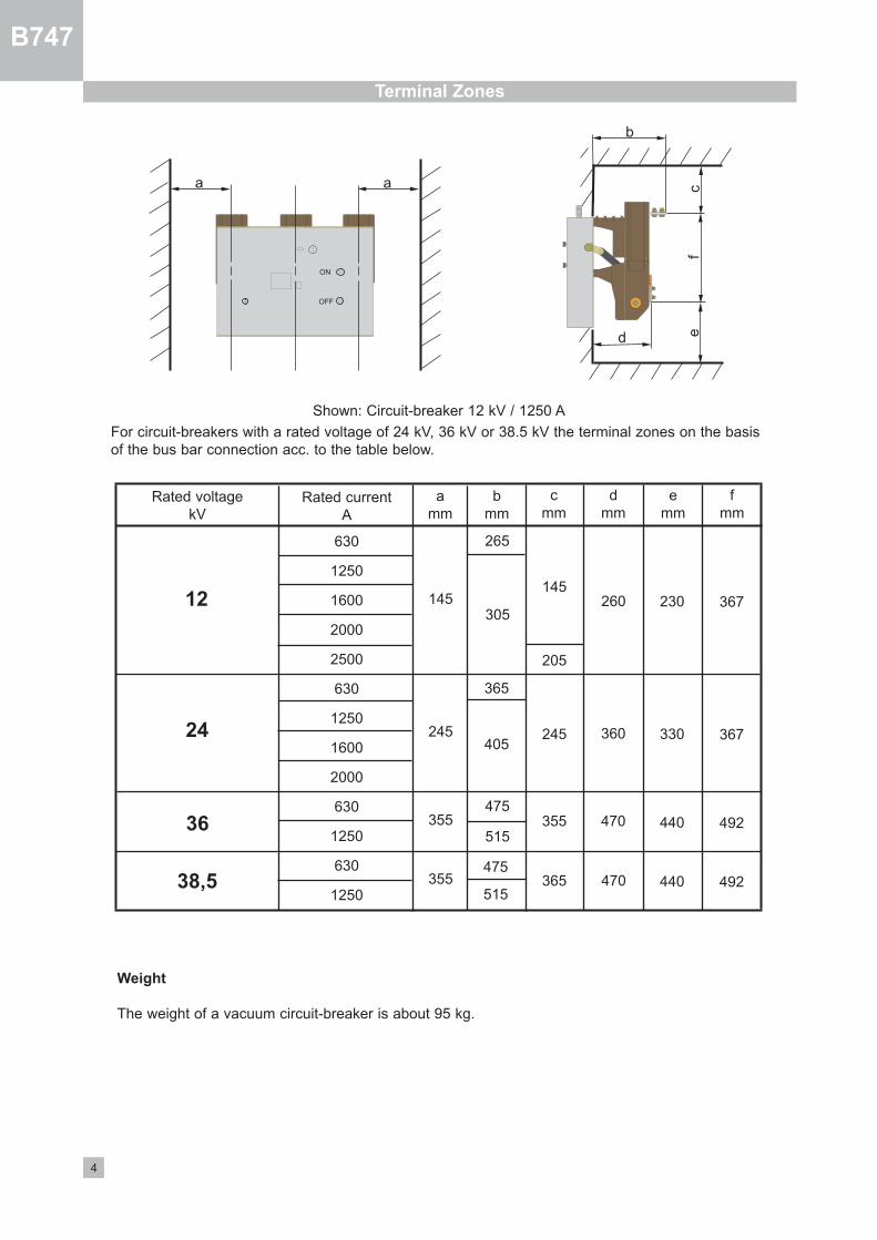
Terminal Zones
Rated voltagekV
Rated currentA
630
1250
1600
2000
2500
630
1250
1600
2000
630
1250
630
1250
amm
bmm
cmm
dmm
emm
fmm
145
245
355
355
367
367
492
492
230
330
440
440
260
360
470
470
145
205
245
265
24
12
36
38,5
305
365
405
475
515
475
515365
355
a a
b
d ef
c
Shown: Circuitbreaker 12 kV / 1250 A
For circuitbreakers with a rated voltage of 24 kV, 36 kV or 38.5 kV the terminal zones on the basisof the bus bar connection acc. to the table below.
Weight
The weight of a vacuum circuitbreaker is about 95 kg.
ON
OFF
B747
5
Interlocking
General
Electrical and mechanical interlocking mechanismsensure that making operation of the circuitbreaker isonly possible when the springloaded energy storagemechanism is loaded and has stored energy to carryout a making / breaking operation.This ensures that the last possible switching operation is always a breaking operation, even if the motoror control voltage should fail.For circuitbreakers in withdrawable design it must beensured that the switch truck can only be moved intothe operating or disconnecting position when the circuitbreaker is switched off and the plug connector isconnected.Interlocking mechanisms also ensure that the switchtruck cannot be removed from the switch panel before the plug connector has been disconnected.
Mechanical Interlocking Mechanisms
Actuators of disconnecting switches can be equipped with a mechanical switchgear interlocking. Forthis purpose the disconnecting switch is mechanically interlocked with the corresponding circuitbreaker.The polling parts scan the position of the circuit
breaker and block its mechanical and electricalmaking operation if the corresponding disconnecting switch is in intermediate position.On the other side, it prevents any operation of thedisconnecting switch when the circuitbreaker is closed.
Electrical Interlocking
Circuitbreakers can be incorporated in electromagnetic branch or interlocking mechanisms. In case ofan electrical interlocking there is a magnetic lockoutmechanism attached to the disconnecting switch orits operating mechanism, where the lockout mechanism is actuated by means of an auxiliary contact ofthe circuitbreaker in such a way that the disconnecting switch can only be operated when the circuitbreaker is opened.On the other hand, the circuitbreaker is actuated bythe disconnecting switch or its actuator in such a waythat it can only be closed in the end positions of thedisconnecting switch.Therefore, the electrical manual making operationmust be provided in the circuitbreaker actuator.
Assembly
All switches of the V… type series are suitable forvertical installation (related to the vacuum switchingtube). For the assembly in switchgear cubicles oron switchgear trucks always pay attention to the following:
The switches must always be mounted on an adequately stable framework construction.
The switches can be attached at 8 bores on thelower and upper side of the switch frame. Therecess on the lower side of the switch frame (seepage 10, picture, area I) must be kept open. 2 boreseach are provided with M12 rivet nuts.When fixing the switch the base frame may not bedistorted. Compensate any unevenness with shims.
Adjust the bus bars in such a way that they rest flatwithout constraint and with overlapping holes on thecontact surfaces of the vacuum circuitbreaker.Before tightening the screws, carefully treat themating surfaces of the bus bars and the vacuum circuitbreaker by applying strokes with a steel brushin crosswise action until bright and wipe off any residue with a clean cloth.
Apply a thin coat of acidfree Vaseline to the brightcontact surfaces and then screw together immediately.For the connection use bolts and nuts M12 – property class 8 – and the appropriate spring elementsand washers.
Attention! When tightening the connecting bolts(tightening torque 70 Nm) always use an appropriatespanner or socket key as counterpart.
To prevent vibrations of the vacuum circuitbreakerfrom reaching other sensitive system elements, werecommend inserting flexible intermediate piecesbetween the switch connections and bus bars. This applies in particular when the bus bar connections to the next device are very short. (Flexibleconnecting pieces can be included in delivery ondesire).
Earthing
Use the marked bore on the upper side of the switchframe to earth the circuitbreaker.
B747
6
Auxiliary Switches • Releases
Auxiliary Switches
For control and signalling purposes the circuitbreakers are equipped with auxiliary switches.These are installed in the covered baseframe andare wired to the female multipole connector (page10, image 9).Their individual contacts are set at the factory –according to the desired details – as making or breaking or pulse contact elements. To achieve thelongest possible pulse duration for the pulsecontact elements, one making and one breakingcontact are connected in series and are set to overlap.In case that one or the other contact had to servean opposite function, it is possible to make thenecessary changes in a few simple steps.
Shunt Releases
are available for DC or AC. They are used most as theyare suitable for both remote control and automatic protection. However, a requirement for their use is theavailability of an auxiliary voltage which must be independent from the network for the tripping on faults.As the coil is only designed for a shorttime current, thecircuit is looped through an auxiliary contact actuatedby the operating shaft, and this breaks the circuit afterthe switching operation has been effected.
Undervoltage Releases
They are also known as lowvoltage releases. They tendto be used when circuitbreakers are to be opened automatically if the supply voltage should drop too low or failcompletely.If the voltage drops below 35% of the rated voltage, thereleases immediately operate and release the breakingoperation.
Indirect Releases
are only used for the automatic fault clearing in case ofoverload or shortcircuit. This type of release is used ifno auxiliary voltage supply is available independent ofthe supply voltage.Indirect releases are included in the secondary circuitof feeder current transformers and are energised whenthe corresponding protective relay is activated. To protect the release contacts of the protective relays fromoverload it is usually necessary to interpose an auxiliary transformer which reduces the current of the maintransformer and limits it to an acceptable level bymeans of saturation (auxiliary transformers which haveto be installed separately from the switch, are not included in delivery).
"Breaker tripped” Indication
When switching off the vacuum switch by means of arelease, the position switch makes a brief contact. Thiscontact making can be used for a signal. For an intentional mechanical opening, a cutout switch breaks thecontact.
Varistor Module
The disconnection of inductive loads in DCcircuits cancause switching surges which endanger the electroniccontrol equipment. In order to prevent this hazard theinductance of the switch actuator and the control(motor, closing coil, shunt release and auxiliary protection) is connected to the varistors in case of DCoperation.
B747
7
Motorantriebe
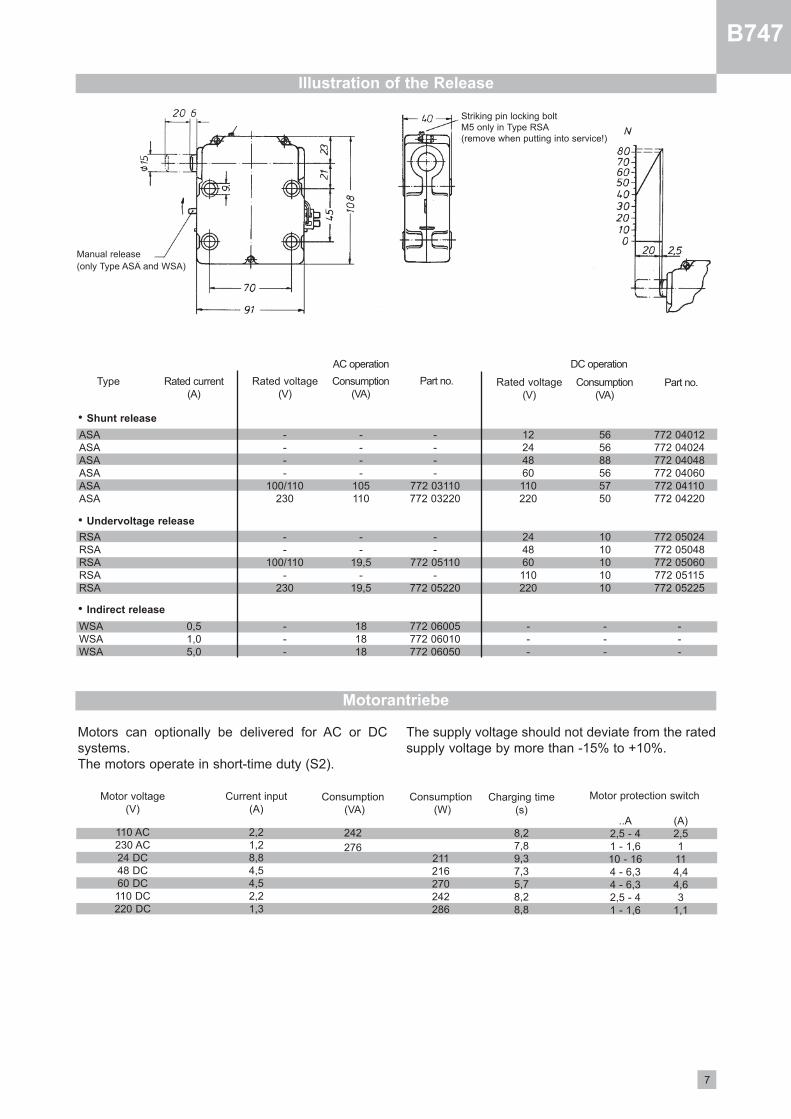
Illustration of the Release
ASAASAASAASAASAASA
RSARSARSARSARSA
WSAWSAWSA
0,51,05,0
12244860110220
244860110220
100/110230
100/110
230
772 03110772 03220
772 05110
772 05220
772 06005772 06010772 06050
565688565750
1010101010
105110
19,5
19,5
181818
772 04012772 04024772 04048772 04060772 04110772 04220
772 05024772 05048772 05060772 05115772 05225
Type Rated current(A)
Rated voltage(V)
AC operation DC operation
Rated voltage(V)
Consumption(VA)
Consumption(VA)
Part no.Part no.
• Shunt release
• Undervoltage release
• Indirect release
Motors can optionally be delivered for AC or DCsystems. The motors operate in shorttime duty (S2).
The supply voltage should not deviate from the ratedsupply voltage by more than 15% to +10%.
Motor protection switchCurrent input (A)
2,21,28,84,54,52,21,3
Consumption(VA)
242
276
Consumption(W)
211216270242286
Charging time(s)
8,27,89,37,35,78,28,8
..A2,5 41 1,610 164 6,34 6,32,5 41 1,6
(A)2,51114,44,63
1,1
Motor voltage(V)
110 AC230 AC24 DC48 DC60 DC110 DC220 DC
Striking pin locking bolt M5 only in Type RSA (remove when putting into service!)
Manual release(only Type ASA and WSA)
B747
8
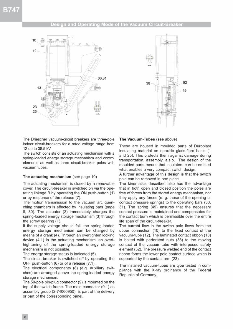
Design and Operating Mode of the Vacuum Circuit-Breaker
The Driescher vacuumcircuit breakers are threepoleindoor circuitbreakers for a rated voltage range from12 up to 38.5 kV.The switch consists of an actuating mechanism with aspringloaded energy storage mechanism and controlelements as well as three circuitbreaker poles withvacuum tubes.
The actuating mechanism (see page 10)
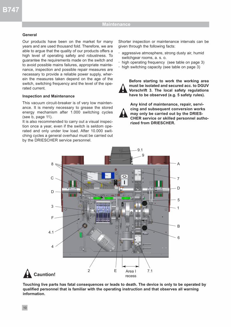
The actuating mechanism is closed by a removablecover. The circuitbreaker is switched on via the operating linkage B by operating the ON pushbutton (1)or by response of the release (7).The motion transmission to the vacuum arc quenching chambers is effected by insulating bars (page8, 30). The actuator (2) immediately charges thespringloaded energy storage mechanism (3) throughthe screw gearing (F).If the supply voltage should fail, the springloadedenergy storage mechanism can be charged bymeans of a crank (4). Through an overtighten lockingdevice (4.1) in the actuating mechanism, an overthightening of the springloaded energy storagemechanism is not possible.The energy storage status is indicated (5).The circuitbreaker is switched off by operating theOFF pushbutton (6) or of a release (7.1).The electrical components (8) (e.g. auxiliary switches) are arranged above the springloaded energystorage mechanism.The 50pole pinplug connector (9) is mounted on thetop of the switch frame. The male connector (9.1) asassembly group (274060950) is part of the deliveryor part of the corresponding panel.
The Vacuum-Tubes (see above)
These are housed in moulded parts of Duroplastinsulating material on epoxide glassfibre basis (1and 25). This protects them against damage duringtransportation, assembly, a.s.o. The design of themoulded parts means that insulators can be omittedwhat enables a very compact switch design.A further advantage of this design is that the switchpole can be removed in one piece. The kinematics described also has the advantagethat in both open and closed position the poles arefree of forces from the stored energy mechanism, northey apply any forces (e. g. those of the opening orcontact pressure springs) to the operating bars (30,31). The spring (49) ensures that the necessarycontact pressure is maintained and compensates forthe contact burn which is permissible over the entirelife span of the circuitbreaker.The current flow in the switch pole flows from theupper connection (10) to the fixed contact of thevacuumtube (12). The laminated contact ribbon (13)is bolted with perforated nuts (38) to the movingcontact of the vacuumtube with interposed safetyelement (52). The pressure welded end of the contactribbon forms the lower pole contact surface which issupported by the contact arm (23).
The installed vacuumtubes are type tested in compliance with the Xray ordinance of the FederalRepublic of Germany.
B747
9
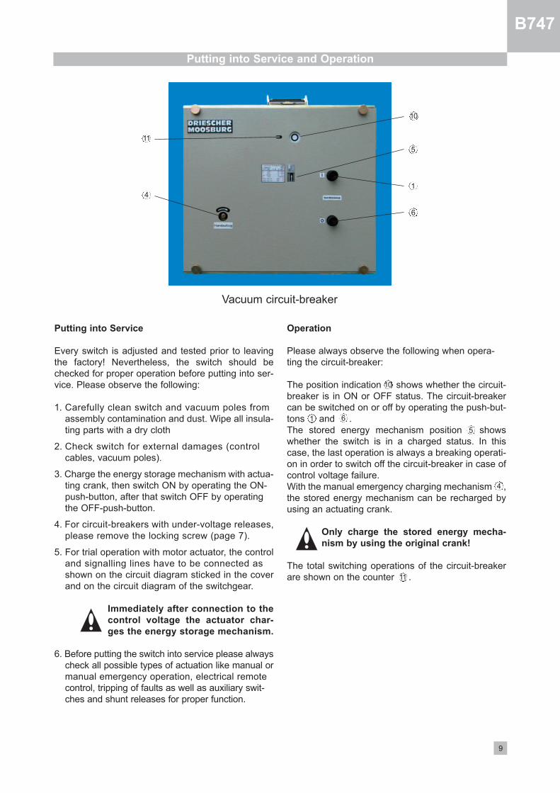
Putting into Service and Operation
Vacuum circuitbreaker
Putting into Service
Every switch is adjusted and tested prior to leavingthe factory! Nevertheless, the switch should bechecked for proper operation before putting into service. Please observe the following:
1. Carefully clean switch and vacuum poles fromassembly contamination and dust. Wipe all insulating parts with a dry cloth
2. Check switch for external damages (controlcables, vacuum poles).
3. Charge the energy storage mechanism with actuating crank, then switch ON by operating the ONpushbutton, after that switch OFF by operating the OFFpushbutton.
4. For circuitbreakers with undervoltage releases,please remove the locking screw (page 7).
5. For trial operation with motor actuator, the controland signalling lines have to be connected asshown on the circuit diagram sticked in the coverand on the circuit diagram of the switchgear.
Immediately after connection to the
control voltage the actuator char-
ges the energy storage mechanism.
6. Before putting the switch into service please alwayscheck all possible types of actuation like manual ormanual emergency operation, electrical remotecontrol, tripping of faults as well as auxiliary switches and shunt releases for proper function.
Operation
Please always observe the following when operating the circuitbreaker:
The position indication shows whether the circuitbreaker is in ON or OFF status. The circuitbreakercan be switched on or off by operating the pushbuttons and .The stored energy mechanism position showswhether the switch is in a charged status. In thiscase, the last operation is always a breaking operation in order to switch off the circuitbreaker in case ofcontrol voltage failure.With the manual emergency charging mechanism ,the stored energy mechanism can be recharged byusing an actuating crank.
Only charge the stored energy mecha-
nism by using the original crank!
The total switching operations of the circuitbreakerare shown on the counter .
1
6
1 6
5
5
5
4
4
10
10
11
11
10
Maintenance
General
Our products have been on the market for manyyears and are used thousand fold. Therefore, we areable to argue that the quality of our products offers ahigh level of operating safety and robustness. Toguarantee the requirements made on the switch andto avoid possible mains failures, appropriate maintenance, inspection and possible repair measures arenecessary to provide a reliable power supply, wherein the measures taken depend on the age of theswitch, switching frequency and the level of the operated current.
Inspection and Maintenance
This vacuum circuitbreaker is of very low maintenance. It is merely necessary to grease the storedenergy mechanism after 1.000 switching cycles(see b, page 11).It is also recommended to carry out a visual inspection once a year, even if the switch is seldom operated and only under low load. After 10.000 switching cycles a general overhaul must be carried outby the DRIESCHER service personnel.
Shorter inspection or maintenance intervals can begiven through the following facts:
• aggressive atmosphere, strong dusty air, humid switchgear rooms, a. s. o.
• high operating frequency (see table on page 3)• high switching capacity (see table on page 3)
Before starting to work the working area
must be isolated and secured acc. to DGUV
Vorschrift 3. The local safety regulations
have to be observed (e.g. 5 safety rules).
Any kind of maintenance, repair, servi-
cing and subsequent conversion works
may only be carried out by the DRIES-
CHER service or skilled personnel autho-
rized from DRIESCHER.
C
B
F
2
3 1
5
6
4
4.1
7
8
9
7.1
DD
B747
E Area IrecessCauntion!
Touching live parts has fatal consequences or leads to death. The device is only to be operated by
qualified personnel that is familiar with the operating instruction and that observes all warning
information.
9.1
A
11
B747
The following points have to be observed during maintenance:
a) Clean the vacuum poles A on the back with a clean, dry cloth from dust and dirt.
b) Lubrication of the stored energy unit;
all bearings and joints of the operating mechanism B the control shaft C the operating shaft bearing D
have to be lubricated with Rivolta S.K.D 4002, places with difficult access have to be lubricated withRivolta S.K.D. 16.
the threaded bush E the screw gearing F
with KLÜBERPLEX BE31102 (Klüber).
c) The burnoff of the contacts in the vacuumtubesmainly depends on the number of shortcircuit breakings and the respective levels of currents applied (see table on page 3).
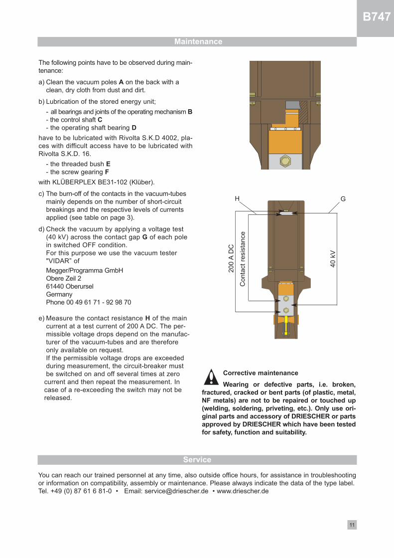
d) Check the vacuum by applying a voltage test (40 kV) across the contact gap G of each pole in switched OFF condition.For this purpose we use the vacuum tester "VIDAR” of
Megger/Programma GmbHObere Zeil 261440 OberurselGermanyPhone 00 49 61 71 92 98 70
e) Measure the contact resistance H of the maincurrent at a test current of 200 A DC. The permissible voltage drops depend on the manufacturer of the vacuumtubes and are therefore only available on request.If the permissible voltage drops are exceeded during measurement, the circuitbreaker must be switched on and off several times at zero
current and then repeat the measurement. In case of a reexceeding the switch may not be released.
Corrective maintenance
Wearing or defective parts, i.e. broken,
fractured, cracked or bent parts (of plastic, metal,
NF metals) are not to be repaired or touched up
(welding, soldering, priveting, etc.). Only use ori-
ginal parts and accessory of DRIESCHER or parts
approved by DRIESCHER which have been tested
for safety, function and suitability.
Maintenance
Conta
ct r
esi
stance
200 A
DC
40 k
V
GH
Service
You can reach our trained personnel at any time, also outside office hours, for assistance in troubleshootingor information on compatibility, assembly or maintenance. Please always indicate the data of the type label.Tel. +49 (0) 87 61 6 810 • Email: [email protected] • www.driescher.de
Order no. 3-81202047 • 07-15
Our range of products includes:
Medium-voltage systems• Single-busbar and duplicate-busbar switchgear• Fixed mounting, withdrawable design and truck-type units• Compact switchgear assemblies• Customer-specific models• Industrial switchgear• Power factor correction and filter equipment
Medium-voltage switches• Indoor load-break switches, disconnectors, and earthing switches (single and triple pole)• Indoor circuit breakers (low oil content and vacuum)• Outdoor load-break switches, disconnectors, and earthing switches (single and triple pole)• Railway switches for power supply and catenary• High-voltage high-breaking-capacity fuses• Customer-specific switches
Low-voltage systems• Open-framework design• Enclosed switchgear (up to 6.300 A)• Motor Control Center (MCC)• Cable and fixed-station distribution cabinets
Low-voltage switches• Switch disconnectors• Switching strips and fuse blocks
Compact sub-station• Concrete construction• Container construction
Driving gear• Hand-operated and motor-operated mechanisms
for indoor and outdoor application
Accessories• For medium and low voltage• For station equipment• Insulators (0,5 kV - 38,5 kV)• Plastic and glass fibre-reinforced plastic screening
Service• Maintenance and Service of all switches and switchgear• Training courses and seminars• Thermography; Live-line working
ELEKTROTECHNISCHE WERKEFRITZ DRIESCHER & SÖHNE GMBHD-85366 MOOSBURG • TEL. +49 87 61 6 81-0 • FAX +49 87 61 68 12 30http://www.driescher.com [email protected]
Dimensions, weights, diagrams and descriptions in this brochure are non-binding. Subject to change without notice.
Printed on chlorine free bleached paper. For nature´s sake.
STROM • SICHER • SCHALTEN


![B747-4 - Cockpit Overview [2005]](https://static.fdocuments.in/doc/165x107/55cf97e9550346d033946457/b747-4-cockpit-overview-2005.jpg)


![B747 DVA Manual[1]](https://static.fdocuments.in/doc/165x107/552c58ac550346e8198b4728/b747-dva-manual1.jpg)