B4: Experience with a Globally-Deployed Software Defined WAN Presenter: Klara Nahrstedt CS 538...
30
B4: Experience with a Globally-Deployed Software Defined WAN Presenter: Klara Nahrstedt CS 538 Advanced Networking Course Based on “B4: Experience with a Globally Deployed Software Defined WAN”, by Sushant Jain et al, ACM SIGCOMM 2013, Hong-Kong, China
-
Upload
kyree-torell -
Category
Documents
-
view
224 -
download
0
Transcript of B4: Experience with a Globally-Deployed Software Defined WAN Presenter: Klara Nahrstedt CS 538...
B4: Experience with a Globally-Deployed
Software Defined WAN Presenter: Klara Nahrstedt
CS 538 Advanced Networking Course
Based on “B4: Experience with a Globally Deployed Software Defined WAN”, by Sushant Jain et al, ACM SIGCOMM 2013, Hong-Kong, China

Overview • Current WAN Situation • Google Situation
• User Access Network• Data Centers Network (B4 Network)
• Problem Description regarding B4 Network• B4 Design • Background on Existing Technologies used in B4• New Approaches used in B4
• Switch design• Routing design• Network controller design • Traffic engineering design
• Experiments• Conclusion

Current WAN Situation
• WAN (Wide Area Networks) must deliver performance and reliability in Internet, delivering terabits/s bandwidth• WAN routers consist of high end specialized equipment being very
expensive due to provisioning of high availability• WANs treat all bits the same and applications are treated the same
• Current Solution:• WAN links are provisioned to 30-40% utilization • WAN is over-provisioned to deliver reliability at very real cost of 2-3x
bandwidth over-provisioning and high end routing gear.

Google WAN Current Situation
• Two types of WAN networks • User-facing network peers – exchanging traffic with other Internet domains
• End user requests and responses are delivered to Google data centers and edge caches• B4 network – providing connectivity among data centers
• Network applications (traffic classes) over B4 network • User data copies (email, documents, audio/video files) to remote data centers
for availability and durability• Remote storage access for computation over inherently distributed data
sources• Large-scale data push synchronizing state across multiple data centers
• Over 90% of internal application traffic runs over B4

Google’s Data Center WAN (B4 Network)
1. Google controls - applications, - Servers, - LANs, all the way to the edge of network2. bandwidth-intensive apps - Perform large-scale data copies from one
site to another; - Adapt transmission rate- Defer to higher priority interactive apps
during failure periods or resource constraints
3. No more than few dozen data center deployments, hence making central control of bandwidthpossible
Problem Description
• How to increase WAN Link utility to close to 100%?• How to decrease cost of bandwidth provisioning and still provide
reliability ? • How to stop over-provisioning?
• Traditional WAN architectures cannot achieve the level of scale, fault tolerance, cost efficiency, and control required for B4

B4 Requirements
• Elastic Bandwidth Demand • Synchronization of datasets across sites demands large amount of bandwidth,
but can tolerate periodic failures with temporary bandwidth reductions
• Moderate number of sites • End application control • Google controls both applications and site networks connected to B4• Google can enforce relative application priorities and control bursts at
network edges (no need for overprovisioning)
• Cost sensitivity• B4’s capacity targets and growth rate led to unsustainable cost projections
Approach for Google’s Data Center WAN • Software Defined Networking architecture (Open Flow) • Dedicated software-based control plane running on commodity servers• Opportunity to reason about global state • Simplified coordination and orchestration for both planned and unplanned
network changes• Decoupling of software and hardware evolution
• Customization of routing and traffic engineering • Rapid iteration of novel protocols• Simplified testing environment• Improved capacity planning • Simplified management through fabric-centric rather than router-centric
WAN view

B4 Design OFA – Open Flow Agent OFC – Open Flow ControllerNCA – Network Control ApplicationNCS – Network Control ServerTE – Traffic Engineering RAP – Routing Application Proxy
Paxos – Family of protocols for solving consensus in network of unreliable processors (Consensus is process of agreeing on one result among group of participants; Paxos is usually used where durability is needed such as in replication).
Quagga – network routing software suite providing implementations of Open Shortest Path First (OSPF), Routing Information Protocol (RIP), Border Gateway Protocol (BGP), and IS-IS

Background
• IS-IS (Intermediate System to Intermediate System) routing protocol – interior gateway protocol (iBGP) routing information within AS – link-state routing protocol (similar to OSPF)• ECMP – Equal-cost multi-path routing• Next hop packet forwarding to single destination can occur over multiple
“best paths”• See animation http://en.wikipedia.org/wiki/Equal-cost_multi-path_routing

Equal-cost multipath routing (ECMP)
• ECMP• Multipath routing strategy that splits traffic over multiple paths
for load balancing
• Why not just round-robin packets?• Reordering (lead to triple duplicate ACK in TCP?)• Different RTT per path (for TCP RTO)…• Different MTUs per path
11
http://www.cs.princeton.edu/courses/archive/spring11/cos461/

Equal-cost multipath routing (ECMP)
• Path-selection via hashing• # buckets = # outgoing links• Hash network information (source/dest IP addrs) to select
outgoing link: preserves flow affinity
12
http://www.cs.princeton.edu/courses/archive/spring11/cos461/

Now: ECMP in datacenters
• Datacenter networks are multi-rooted tree• Goal: Support for 100,000s of servers• Recall Ethernet spanning tree problems: No loops• L3 routing and ECMP: Take advantage of multiple paths
13
http://www.cs.princeton.edu/courses/archive/spring11/cos461/

Switch Design
• Traditional Design of routing equipment • Deep buffers• Very large forwarding tables• Hardware support for high availability
• B4 Design • Avoid deep buffers while avoiding expensive packet drops• Run across relatively small number of data centers, hence smaller forwarding
tables• Switch failures caused more by software than hardware, hence separation of
software functions off the switch hardware minimizes failures

Switch Design • Two-stage switch
• 128-port 10G switch • 24 individual 16x10G non-blocking switch chips ( Spine Layer)
• Forwarding Protocol • Ingress chip bounces incoming chip to Spine• Spine forwards packets to appropriate output chip (unless dest on the same ingress chip)
• Open Flow Agent (OFA)• User-level process running on switch hardware• OFA connects to OFC accepting OF (OpenFlow) commands• OFA translates OF messages into driver commands to set chip forwarding table entries• Challenges:
• OFA exports abstraction of a single non-blocking switch with hundreds of 10 Gbps ports. However, underlying switch has multiple physical switch chips, each with their own forwarding tables.
• OpenFlow architecture considers neutral version of forwarding table entries, but switches have many linked forwarding tables of various sizes and semantics.

Network Control Design • Each site has multiple NCS• NCS and switches share dedicated
Out of band control-plane network
• One of NCS serves as leader • Paxos handles leader election • Paxos instances perform application-level failure
detection among pre-configured set of available replicas for given piece of control functions.
• Modified Onix is used• Network Information Base (NIB) contains
network state (topology, trunk configurations, link status)
• OFC replicas are warm standbys• OFA maintains multiple connections to
multiple OFCs• Active communication to only one OFC at a time

Routing Design • Use Open Source Quagga stack for
BGP/ISIS on NCS• Develop RAP to provide connectivity
between Quagga and OF switches for• BGP/ISIS route updates• Routing protocol packets flowing
between switches and Quagga• Interface updates from switches to
Quagga• Translation from RIB entries forming a
network level view of global connectivity to low level HW tables
• Translation of RIB into two Open Flow tables

Traffic Engineering Architecture
• TE Server operates over states• Network topology • Flow Group (FG)
• Applications are aggregated to FG• {source site, dest site, QoS}
• Tunnel (T)• Site-level path in network • A->B->C
• Tunnel Group (TG) • Map of FGs to set of tunnels and
corresponding weights • Weight specifies fraction of FG
traffic to be forwarded along each tunnel

Bandwidth Functions
• Each application is associated with bandwidth function • Bandwidth Function
• Gives Contract between app and B4• Specifies BW allocation to app given
flow’s relative priority on a scale, called fair share
• Derived from admin-specific static weights (slope) specifying app priority
• Configured, measured and provided to TE via Bandwidth Enforcer

TE Optimization Algorithm • Two components• Tunnel Group Generation -
allocates BW to FGs using bandwidth functions to prioritize at bottleneck edges• Tunnel Group Quantization
– changes split ratios in each TG to match granularity supported by switch tables

TE Optimization Algorithm (2) • Tunnel Group Generation
Algorithm• Allocates BW to FGs based on
demand and priority• Allocates edge capacity among
FGs based on BW function • Receive either equal fair share or
fully satisfy their demand
• Preferred tunnel for FG is minimum cost path that does not include bottleneck edge • Algorithm terminates when
each FG is satisfied or no preferred tunnel exists
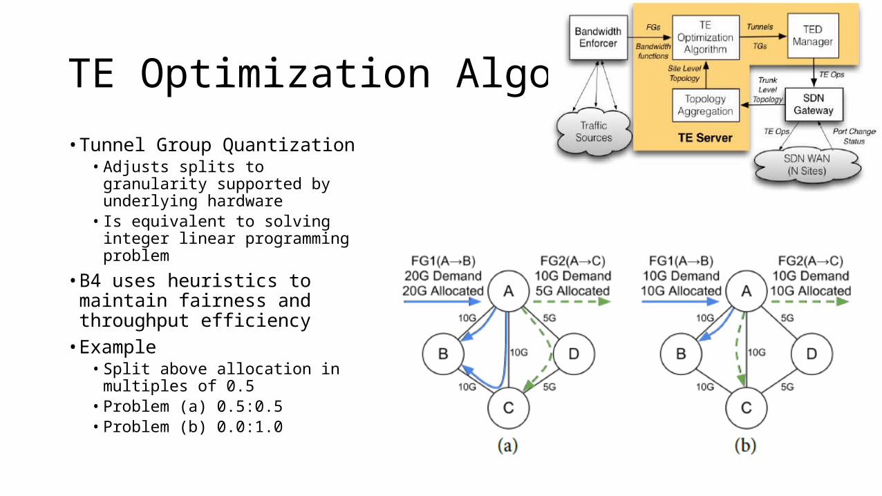
TE Optimization Algorithm (3)
• Tunnel Group Quantization • Adjusts splits to granularity
supported by underlying hardware • Is equivalent to solving integer
linear programming problem
• B4 uses heuristics to maintain fairness and throughput efficiency • Example
• Split above allocation in multiples of 0.5
• Problem (a) 0.5:0.5• Problem (b) 0.0:1.0

TE Protocol
• B4 switches operate in three roles: • Encapsulating switch initiates tunnels and splits traffic between them• Transit switch forwards packets based on outer header• Decapsulating switch terminates tunnels and then forwards packets using regular routes
• Source site switches implement FGs• Switch maps packets to FG when their destination IP adr matches one of the prefixes
associated with FG• Each incoming packet hashes to one of Tunnels associated with TG in desired ratio• Each site in tunnel path maintains per-tunnel forwarding rules• Source site switches encapsulate packet with outer IP header (tunnel-ID) whose
destination IP address uniquely identifies tunnel
• Installing tunnel requires configuring switches at multiple sites

TE Protocol Example

Coordination between Routing and TE
• B4 supports both • Shortest path routing and • TE routing protocol
• This is very robust solution since if TE gets disabled, underlying routing continues working
• We require support for multiple forwarding tables • At OpenFlow level, we use RAP, mapping
different flows and groups to appropriate HW tables – routing/BGP populates LPM (Last Prefix Match) table with appropriate entries
• AT TE level, we use Access Control List (ACL) table to set desired forwarding behavior

Role of Traffic Engineering Database (TED)• TE server coordinates T/TG/FG rule
installation across multiple OFCs. • TE optimization output is translated to
per-site TED• TED captures state needed to forward
packets along multiple paths• Each OFC uses TED to set forwarding
states at individual switches• TED maintains key-value store for
global tunnels, tunnel groups, and flow groups• TE operation (TE op) can
add/delete/modify exactly one TED entry at one OFC

Other TE Issues
• What are some of the other issues with TE?• How would you synchronize TED between TE and OFC? • What are other issues related to reliability of TE, OFC, TED, etc? • ….
Nahrstedt, Klara
dependencies among ops
Nahrstedt, Klara
synchronizing TED between TE and OFC
Nahrstedt, Klara
ordering issues
Nahrstedt, Klara
TE op failures
Impact of Failures
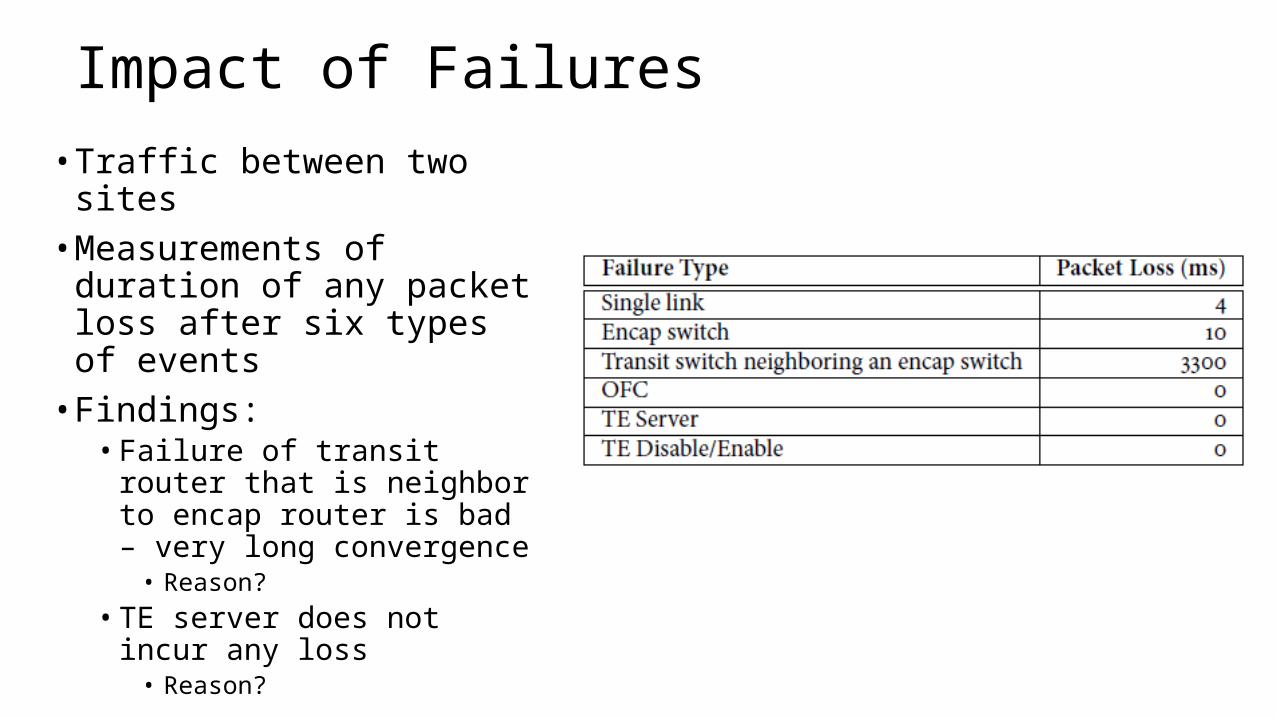
• Traffic between two sites• Measurements of duration of
any packet loss after six types of events• Findings: • Failure of transit router that is
neighbor to encap router is bad – very long convergence• Reason?
• TE server does not incur any loss• Reason?

Utilization
Site-to-site edge utilization
Link utilization (effectivenessOf hashing)

Conclusions – Experience from Outage • Scalability and latency of packet IO path between OFA and OFC is critical
• Why? • How would you remedy problems?
• OFA should be asynchronous and mutli-threaded for more parallelism• Why?
• Loss of control connectivity between TE and OFC does not invalidate forwarding state• Why not?
• TE must be more adaptive to failed/unresponsive OFCs when modifying TGs that depend on creating new Tunnels• Why?
• What other issues do you see with B4 design?