B.1 NFV ISG PoC Report - ETSI · ETSI B.1 NFV ISG PoC Report B.1.1 PoC Project Completion Status...
9
ETSI B.1 NFV ISG PoC Report B.1.1 PoC Project Completion Status • Overall PoC Project Completion Status: Complete. Scenarios 1, 2 and 3 have been completed and demonstrated. The demonstrations showed how a decomposed VNF design enables efficient data processing that minimizes the resource usage. B.1.2 NFV PoC Project Participants • PoC Project Name: PoC#43 Towards an efficient Data Plane processing. • Network Operators / Service Providers: o Telefónica (Contact: Francisco Javier Ramón Salguero [email protected]) • Manufacturer A: o Keynetic Technologies (Contact: Jokin Garay [email protected]) • Manufacturer B: o Hewlett Packard Enterprise (Contact: Enrique Matorras [email protected]) • Additional members (research): o University of the Basque Country UPV/EHU (Contact: Eduardo Jacob [email protected]) B.1.3 Confirmation of PoC Event Occurrence • PoC Demonstration Event Details: o The PoC demonstration took place during the NFV#17, held from February 21 st through to February 24 th in Bilbao, Spain. Image of the demo setup is shown in Figure 1, whereas Figure 2 shows a presentation of the PoC demo to the members of the NFV TST workgroup.
Transcript of B.1 NFV ISG PoC Report - ETSI · ETSI B.1 NFV ISG PoC Report B.1.1 PoC Project Completion Status...
ETSI
B.1 NFV ISG PoC Report
B.1.1 PoC Project Completion Status
• Overall PoC Project Completion Status: Complete.
Scenarios 1, 2 and 3 have been completed and demonstrated. The demonstrations showed how a decomposed
VNF design enables efficient data processing that minimizes the resource usage.
B.1.2 NFV PoC Project Participants
• PoC Project Name: PoC#43 Towards an efficient Data Plane processing.
• Network Operators / Service Providers:
o Telefónica (Contact: Francisco Javier Ramón Salguero [email protected])
• Manufacturer A:
o Keynetic Technologies (Contact: Jokin Garay [email protected])
• Manufacturer B:
o Hewlett Packard Enterprise (Contact: Enrique Matorras [email protected])
• Additional members (research):
o University of the Basque Country UPV/EHU (Contact: Eduardo Jacob [email protected])
B.1.3 Confirmation of PoC Event Occurrence
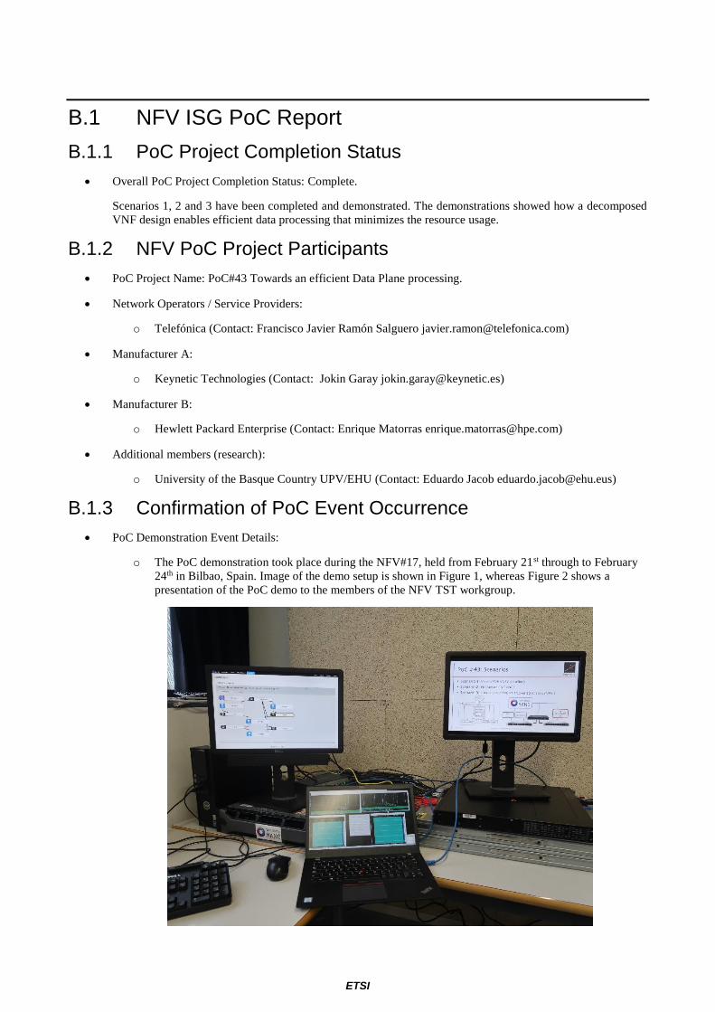
• PoC Demonstration Event Details:
o The PoC demonstration took place during the NFV#17, held from February 21st through to February
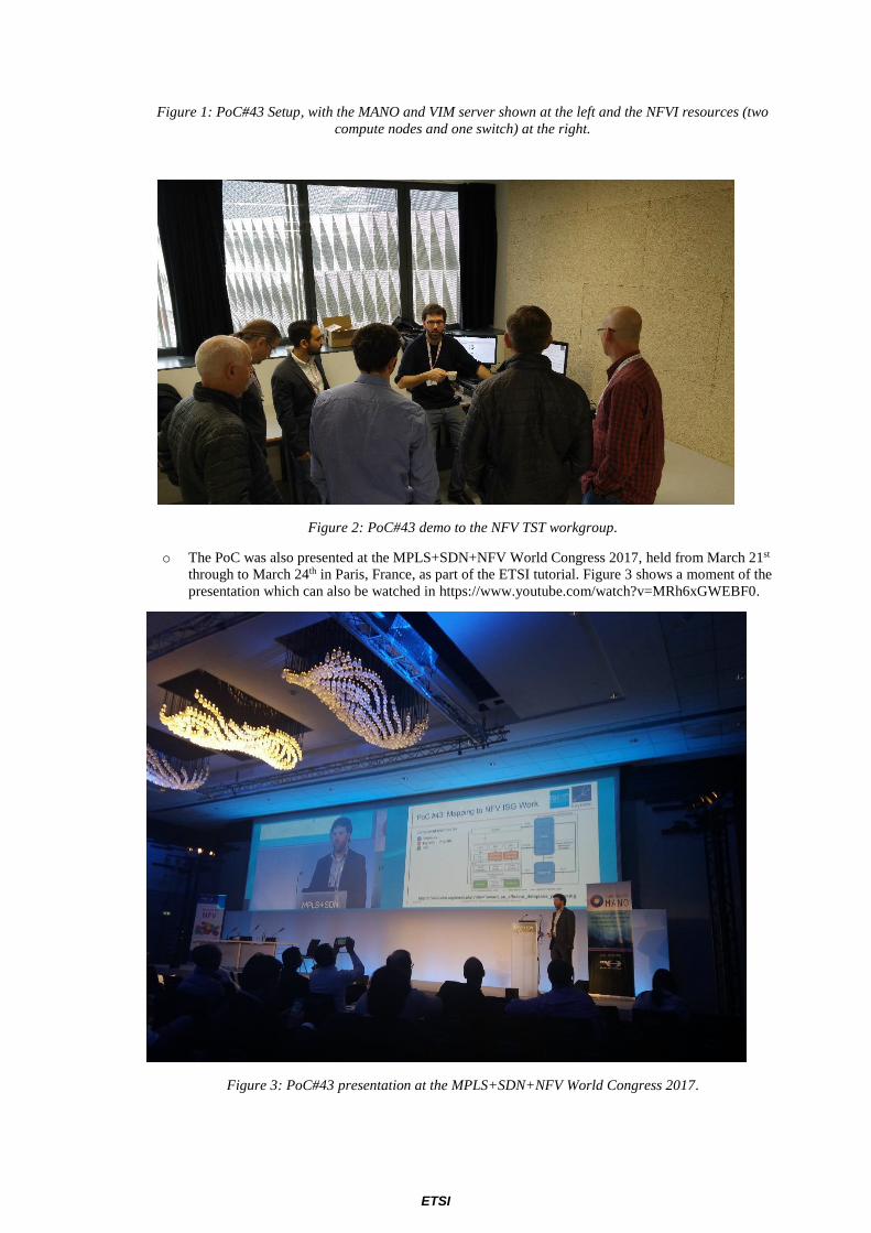
24th in Bilbao, Spain. Image of the demo setup is shown in Figure 1, whereas Figure 2 shows a
presentation of the PoC demo to the members of the NFV TST workgroup.
ETSI
Figure 1: PoC#43 Setup, with the MANO and VIM server shown at the left and the NFVI resources (two
compute nodes and one switch) at the right.
Figure 2: PoC#43 demo to the NFV TST workgroup.
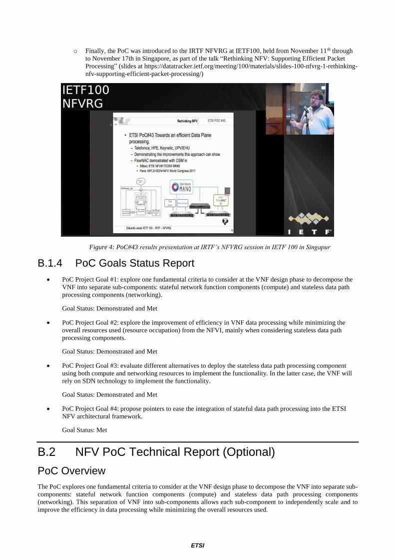
o The PoC was also presented at the MPLS+SDN+NFV World Congress 2017, held from March 21st
through to March 24th in Paris, France, as part of the ETSI tutorial. Figure 3 shows a moment of the
presentation which can also be watched in https://www.youtube.com/watch?v=MRh6xGWEBF0.
Figure 3: PoC#43 presentation at the MPLS+SDN+NFV World Congress 2017.
ETSI
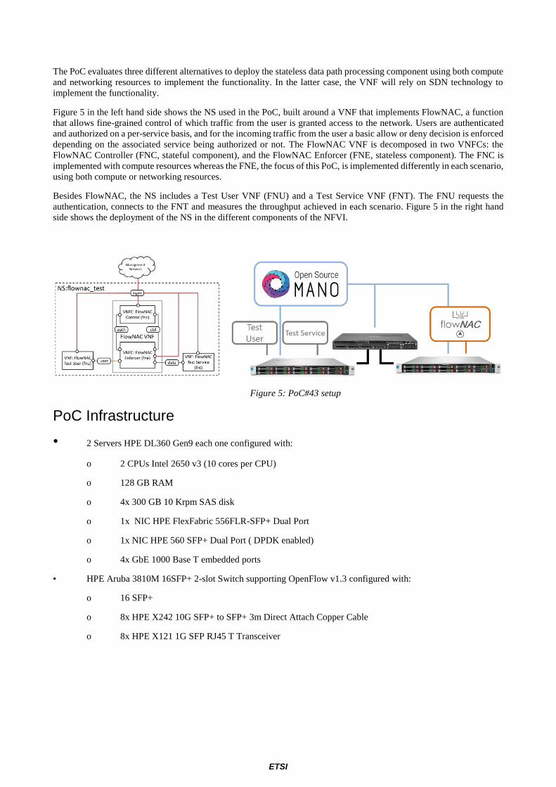
o Finally, the PoC was introduced to the IRTF NFVRG at IETF100, held from November 11 th through
to November 17th in Singapore, as part of the talk “Rethinking NFV: Supporting Efficient Packet
Processing” (slides at https://datatracker.ietf.org/meeting/100/materials/slides-100-nfvrg-1-rethinking-
nfv-supporting-efficient-packet-processing/)
Figure 4: PoC#43 results presentation at IRTF’s NFVRG session in IETF 100 in Singapur
B.1.4 PoC Goals Status Report
• PoC Project Goal #1: explore one fundamental criteria to consider at the VNF design phase to decompose the
VNF into separate sub-components: stateful network function components (compute) and stateless data path
processing components (networking).
Goal Status: Demonstrated and Met
• PoC Project Goal #2: explore the improvement of efficiency in VNF data processing while minimizing the
overall resources used (resource occupation) from the NFVI, mainly when considering stateless data path
processing components.
Goal Status: Demonstrated and Met
• PoC Project Goal #3: evaluate different alternatives to deploy the stateless data path processing component
using both compute and networking resources to implement the functionality. In the latter case, the VNF will
rely on SDN technology to implement the functionality.
Goal Status: Demonstrated and Met
• PoC Project Goal #4: propose pointers to ease the integration of stateful data path processing into the ETSI
NFV architectural framework.
Goal Status: Met
B.2 NFV PoC Technical Report (Optional)
PoC Overview
The PoC explores one fundamental criteria to consider at the VNF design phase to decompose the VNF into separate sub-
components: stateful network function components (compute) and stateless data path processing components
(networking). This separation of VNF into sub-components allows each sub-component to independently scale and to
improve the efficiency in data processing while minimizing the overall resources used.
ETSI
The PoC evaluates three different alternatives to deploy the stateless data path processing component using both compute
and networking resources to implement the functionality. In the latter case, the VNF will rely on SDN technology to
implement the functionality.
Figure 5 in the left hand side shows the NS used in the PoC, built around a VNF that implements FlowNAC, a function
that allows fine-grained control of which traffic from the user is granted access to the network. Users are authenticated
and authorized on a per-service basis, and for the incoming traffic from the user a basic allow or deny decision is enforced
depending on the associated service being authorized or not. The FlowNAC VNF is decomposed in two VNFCs: the
FlowNAC Controller (FNC, stateful component), and the FlowNAC Enforcer (FNE, stateless component). The FNC is
implemented with compute resources whereas the FNE, the focus of this PoC, is implemented differently in each scenario,
using both compute or networking resources.
Besides FlowNAC, the NS includes a Test User VNF (FNU) and a Test Service VNF (FNT). The FNU requests the
authentication, connects to the FNT and measures the throughput achieved in each scenario. Figure 5 in the right hand
side shows the deployment of the NS in the different components of the NFVI.
Figure 5: PoC#43 setup
PoC Infrastructure
• 2 Servers HPE DL360 Gen9 each one configured with:
o 2 CPUs Intel 2650 v3 (10 cores per CPU)
o 128 GB RAM
o 4x 300 GB 10 Krpm SAS disk
o 1x NIC HPE FlexFabric 556FLR-SFP+ Dual Port
o 1x NIC HPE 560 SFP+ Dual Port ( DPDK enabled)
o 4x GbE 1000 Base T embedded ports
• HPE Aruba 3810M 16SFP+ 2-slot Switch supporting OpenFlow v1.3 configured with:
o 16 SFP+
o 8x HPE X242 10G SFP+ to SFP+ 3m Direct Attach Copper Cable
o 8x HPE X121 1G SFP RJ45 T Transceiver
ETSI
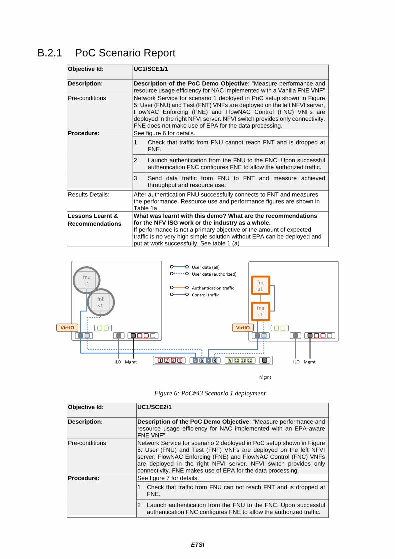
B.2.1 PoC Scenario Report
Objective Id: UC1/SCE1/1
Description: Description of the PoC Demo Objective: "Measure performance and resource usage efficiency for NAC implemented with a Vanilla FNE VNF"
Pre-conditions Network Service for scenario 1 deployed in PoC setup shown in Figure 5: User (FNU) and Test (FNT) VNFs are deployed on the left NFVI server, FlowNAC Enforcing (FNE) and FlowNAC Control (FNC) VNFs are deployed in the right NFVI server. NFVI switch provides only connectivity. FNE does not make use of EPA for the data processing.
Procedure: See figure 6 for details.
1 Check that traffic from FNU cannot reach FNT and is dropped at FNE.
2 Launch authentication from the FNU to the FNC. Upon successful authentication FNC configures FNE to allow the authorized traffic.
3 Send data traffic from FNU to FNT and measure achieved throughput and resource use.
Results Details: After authentication FNU successfully connects to FNT and measures the performance. Resource use and performance figures are shown in Table 1a.
Lessons Learnt &
Recommendations
What was learnt with this demo? What are the recommendations for the NFV ISG work or the industry as a whole. If performance is not a primary objective or the amount of expected traffic is no very high simple solution without EPA can be deployed and put at work successfully. See table 1 (a)
Figure 6: PoC#43 Scenario 1 deployment
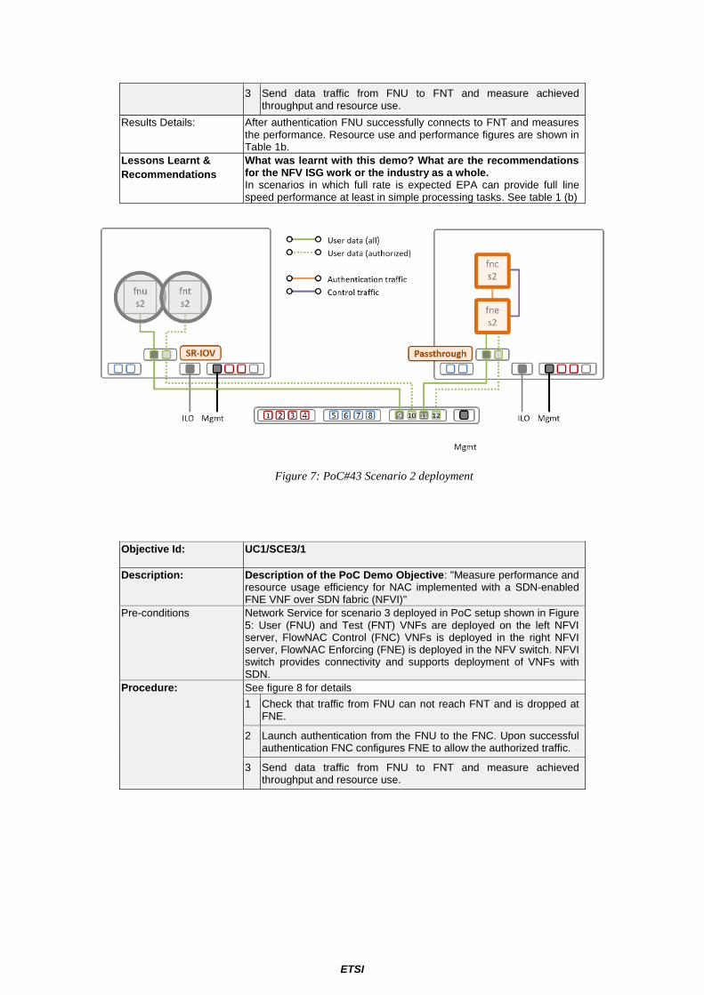
Objective Id: UC1/SCE2/1
Description: Description of the PoC Demo Objective: "Measure performance and resource usage efficiency for NAC implemented with an EPA-aware FNE VNF"
Pre-conditions Network Service for scenario 2 deployed in PoC setup shown in Figure 5: User (FNU) and Test (FNT) VNFs are deployed on the left NFVI server, FlowNAC Enforcing (FNE) and FlowNAC Control (FNC) VNFs are deployed in the right NFVI server. NFVI switch provides only connectivity. FNE makes use of EPA for the data processing.
Procedure: See figure 7 for details.
1 Check that traffic from FNU can not reach FNT and is dropped at FNE.
2 Launch authentication from the FNU to the FNC. Upon successful authentication FNC configures FNE to allow the authorized traffic.
ETSI
3 Send data traffic from FNU to FNT and measure achieved throughput and resource use.
Results Details: After authentication FNU successfully connects to FNT and measures the performance. Resource use and performance figures are shown in Table 1b.
Lessons Learnt &
Recommendations
What was learnt with this demo? What are the recommendations for the NFV ISG work or the industry as a whole. In scenarios in which full rate is expected EPA can provide full line speed performance at least in simple processing tasks. See table 1 (b)
Figure 7: PoC#43 Scenario 2 deployment
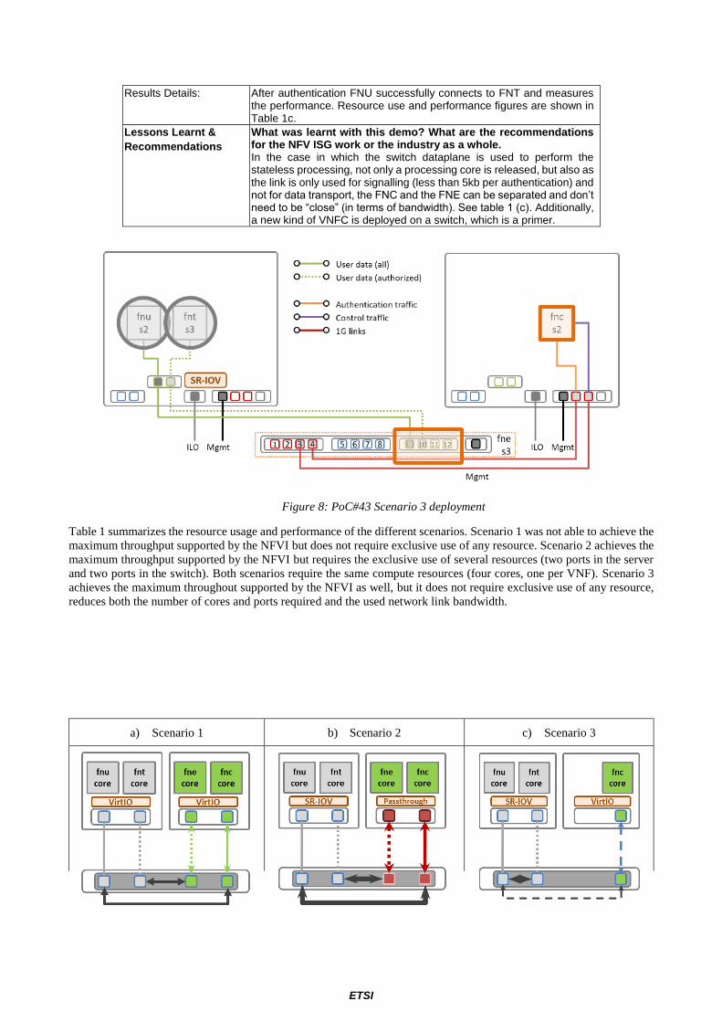
Objective Id: UC1/SCE3/1
Description: Description of the PoC Demo Objective: "Measure performance and resource usage efficiency for NAC implemented with a SDN-enabled FNE VNF over SDN fabric (NFVI)"
Pre-conditions Network Service for scenario 3 deployed in PoC setup shown in Figure 5: User (FNU) and Test (FNT) VNFs are deployed on the left NFVI server, FlowNAC Control (FNC) VNFs is deployed in the right NFVI server, FlowNAC Enforcing (FNE) is deployed in the NFV switch. NFVI switch provides connectivity and supports deployment of VNFs with SDN.
Procedure: See figure 8 for details
1 Check that traffic from FNU can not reach FNT and is dropped at FNE.
2 Launch authentication from the FNU to the FNC. Upon successful authentication FNC configures FNE to allow the authorized traffic.
3 Send data traffic from FNU to FNT and measure achieved throughput and resource use.
ETSI
Results Details: After authentication FNU successfully connects to FNT and measures the performance. Resource use and performance figures are shown in Table 1c.
Lessons Learnt &
Recommendations
What was learnt with this demo? What are the recommendations for the NFV ISG work or the industry as a whole. In the case in which the switch dataplane is used to perform the stateless processing, not only a processing core is released, but also as the link is only used for signalling (less than 5kb per authentication) and not for data transport, the FNC and the FNE can be separated and don’t need to be “close” (in terms of bandwidth). See table 1 (c). Additionally, a new kind of VNFC is deployed on a switch, which is a primer.
Figure 8: PoC#43 Scenario 3 deployment
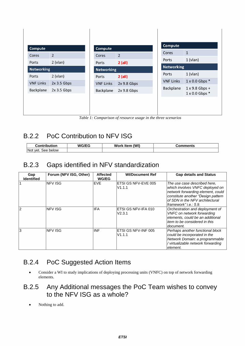
Table 1 summarizes the resource usage and performance of the different scenarios. Scenario 1 was not able to achieve the
maximum throughput supported by the NFVI but does not require exclusive use of any resource. Scenario 2 achieves the
maximum throughput supported by the NFVI but requires the exclusive use of several resources (two ports in the server
and two ports in the switch). Both scenarios require the same compute resources (four cores, one per VNF). Scenario 3
achieves the maximum throughout supported by the NFVI as well, but it does not require exclusive use of any resource,
reduces both the number of cores and ports required and the used network link bandwidth.
a) Scenario 1 b) Scenario 2 c) Scenario 3
ETSI
Table 1: Comparison of resource usage in the three scenarios
B.2.2 PoC Contribution to NFV ISG
Contribution WG/EG Work Item (WI) Comments
Not yet. See below
B.2.3 Gaps identified in NFV standardization
Gap Identified
Forum (NFV ISG, Other) Affected WG/EG
WI/Document Ref Gap details and Status
1 NFV ISG EVE ETSI GS NFV-EVE 005 V1.1.1
The use case described here, which involves VNFC deployed on network forwarding element, could constitute another “Design pattern of SDN in the NFV architectural framework” i.e.: 5.9.
2 NFV ISG IFA ETSI GS NFV-IFA 010 V2.3.1
Orchestration and deployment of VNFC on network forwarding elements, could be an additional item to be considered in this document.
3 NFV ISG INF ETSI GS NFV-INF 005 V1.1.1
Perhaps another functional block could be incorporated in the Network Domain: a programmable / virtualizable network forwarding element.
B.2.4 PoC Suggested Action Items
• Consider a WI to study implications of deploying processing units (VNFC) on top of network forwarding
elements.
B.2.5 Any Additional messages the PoC Team wishes to convey to the NFV ISG as a whole?
• Nothing to add.
ETSI
B.2.6 Any Additional messages the PoC Team wishes to convey to Network Operators and Service Providers?
• Nothing to add.