B0010 - ARC32 Robotics and Servo Controller Data Sheet · • 2 User Controllable LEDs ... C4 C3 C1...
19
B0010 - ARC32 Robotics and Servo Controller Data Sheet B0010 - ARC32 Robotics and Servo Controller Data Sheet (c) 2010 BasicMicro. All Rights Reserved.
-
Upload
nguyentuyen -
Category
Documents
-
view
223 -
download
0
Transcript of B0010 - ARC32 Robotics and Servo Controller Data Sheet · • 2 User Controllable LEDs ... C4 C3 C1...

B0010 - ARC32 Robotics and Servo ControllerData Sheet
B0010 - ARC32 Robotics and Servo Controller Data Sheet
(c) 2010 BasicMicro. All Rights Reserved.

(c) 2010 BasicMicro. All Rights Reserved.
B0010 - ARC32 Robotics and Servo Controller Data Sheet
2
Feature Overview:
• Complete Robotics Controller• 32 Servo Controller• Servos Controlled by Hardware• BasicATOM Pro Based• USB Built-in• 2 UARTS• 20 Analog Channels• 56K Code Space• 32 Bit Hardware Math• 32K EEPROM• 1A Regulator• External Servo Power Capable• 2 User Controllable LEDs• 1 Power LED• Battery Voltage Software Detectable• Small Foot Print 3” x 2.3”
Basic DescriptionThe ARC32 is a robotics controller with advance hardware to control up to 32 servos in the background. The ARC32 uses a hybrid hardware solution to drive the servos with less than 1% CPU time. In addition to being based on a blazing fast 32 bit microcontroller, its the only affordable robotics controller with integrated 32 servo control. The ARC32 is the fi rst to combine an easily programmable robotics controller with a 32 channel servo controller.
The ARC32 is based on the BasicATOM Pro with an increased system clock of 20MHz and 56K of code space. All 32 servo headers have analog capabilities. Each block of 16 servo headers can be powered from a different power source making the ARC32 the perfect solution for high servo count robotics. Its one of the few solutions with many real would example applications.
BATTD4
D3
D2
C4
C3
C1 C10
R2
U1
U2
C6
J5U4
C5
R12
Y1C2
R1
D1
J1JP5
U3
R11
STATUS
PWR
R10R9
RS
T
0123
4567
891011
12131415
16171819
20212223
24252627
R46
R42
R20
R47
AS
SY:
1015
08-0
3
VCC VSVCCVS Basicmicro.com (c) 2011
7531
+ S1 - + S2 -+ -
28293031
AUX2
VCC VS
JP6
AU
X1
1 3 5 7R
17
J4
RX TX RE
S
R3
(c) 2010 BasicMicro. All Rights Reserved.
B0010 - ARC32 Robotics and Servo Controller Data Sheet
3
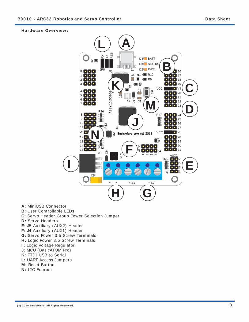
Hardware Overview:
A: MiniUSB ConnectorB: User Controllable LEDsC: Servo Header Group Power Selection JumperD: Servo HeadersE: J5 Auxiliary (AUX2) HeaderF: J4 Auxiliary (AUX1) HeaderG: Servo Power 3.5 Screw TerminalsH: Logic Power 3.5 Screw TerminalsI: Logic Voltage RegulatorJ: MCU (BasicATOM Pro)K: FTDI USB to SerialL: UART Access JumpersM: Reset ButtonN: I2C Eeprom
BATTD4
D3
D2
C4
C3
C1 C10
R2
U1
U2
C6
J5U4
C5
R12
Y1C2
R1
D1
J1JP5
U3
R11
STATUS
PWR
R10R9
RS
T
0123
4567
89
1011
12131415
16171819
20212223
24252627
R46
R42
R20
R47A
SS
Y:10
1508
-03
VCC VSVCCVS Basicmicro.com (c) 2011
7531
+ S1 - + S2 -+ -
28293031
AUX2
VCC VS
JP6
AU
X1
1 3 5 7R
17
J4
RX TX RE
S
R3
A
B
C
D
EF
GH
I
J
K
L
M
N

(c) 2010 BasicMicro. All Rights Reserved.
B0010 - ARC32 Robotics and Servo Controller Data Sheet
4
BATTD4
D3
D2
C4
C3
C1 C10
R2
U1
U2
C6
J5
U4
C5
R12
Y1C2
R1
D1
J1JP5
U3
R11
STATUS
PWR
R10R9
RS
T
0123
4567
891011
12131415
16171819
20212223
24252627
R46
R42
R20
R47
AS
SY:
1015
08-0
3
VCC VSVCCVS Basicmicro.com (c) 2011
7531
+ S1 - + S2 -+ -
28293031
AUX2
VCC VS
JP6
AU
X1
1 3 5 7R
17J4
RX TX RE
S
R3
Dimensions:
Board Edge: 2.3”W X 3”LHole Pattern: 0.125D, 2”W x 2.7”H
2.3”
3”
2”
2.7”
(c) 2010 BasicMicro. All Rights Reserved.
B0010 - ARC32 Robotics and Servo Controller Data Sheet
5
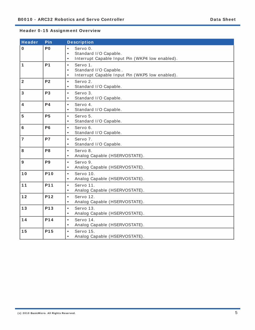
Header 0-15 Assignment Overview
Header Pin Description0 P0 • Servo 0.
• Standard I/O Capable.• Interrupt Capable Input Pin (WKP4 low enabled).
1 P1 • Servo 1.• Standard I/O Capable..• Interrupt Capable Input Pin (WKP5 low enabled).
2 P2 • Servo 2.• Standard I/O Capable.
3 P3 • Servo 3.• Standard I/O Capable.
4 P4 • Servo 4.• Standard I/O Capable.
5 P5 • Servo 5.• Standard I/O Capable.
6 P6 • Servo 6.• Standard I/O Capable.
7 P7 • Servo 7.• Standard I/O Capable.
8 P8 • Servo 8.• Analog Capable (HSERVOSTATE).
9 P9 • Servo 9.• Analog Capable (HSERVOSTATE).
10 P10 • Servo 10.• Analog Capable (HSERVOSTATE).
11 P11 • Servo 11.• Analog Capable (HSERVOSTATE).
12 P12 • Servo 12.• Analog Capable (HSERVOSTATE).
13 P13 • Servo 13.• Analog Capable (HSERVOSTATE).
14 P14 • Servo 14.• Analog Capable (HSERVOSTATE).
15 P15 • Servo 15.• Analog Capable (HSERVOSTATE).
(c) 2010 BasicMicro. All Rights Reserved.
B0010 - ARC32 Robotics and Servo Controller Data Sheet
6
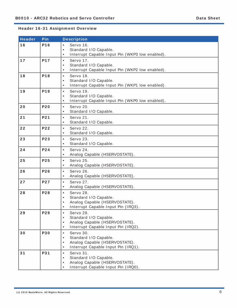
Header 16-31 Assignment Overview
Header Pin Description16 P16 • Servo 16.
• Standard I/O Capable.• Interrupt Capable Input Pin (WKP3 low enabled).
17 P17 • Servo 17.• Standard I/O Capable.• Interrupt Capable Input Pin (WKP2 low enabled).
18 P18 • Servo 18.• Standard I/O Capable.• Interrupt Capable Input Pin (WKP1 low enabled).
19 P19 • Servo 19.• Standard I/O Capable.• Interrupt Capable Input Pin (WKP0 low enabled).
20 P20 • Servo 20.• Standard I/O Capable.
21 P21 • Servo 21.• Standard I/O Capable.
22 P22 • Servo 22.• Standard I/O Capable.
23 P23 • Servo 23.• Standard I/O Capable.
24 P24 • Servo 24.• Analog Capable (HSERVOSTATE).
25 P25 • Servo 25.• Analog Capable (HSERVOSTATE).
26 P26 • Servo 26.• Analog Capable (HSERVOSTATE).
27 P27 • Servo 27.• Analog Capable (HSERVOSTATE).
28 P28 • Servo 28.• Standard I/O Capable.• Analog Capable (HSERVOSTATE).• Interrupt Capable Input Pin (IRQ3).
29 P29 • Servo 29.• Standard I/O Capable.• Analog Capable (HSERVOSTATE).• Interrupt Capable Input Pin (IRQ2).
30 P30 • Servo 30.• Standard I/O Capable.• Analog Capable (HSERVOSTATE).• Interrupt Capable Input Pin (IRQ1).
31 P31 • Servo 31.• Standard I/O Capable.• Analog Capable (HSERVOSTATE).• Interrupt Capable Input Pin (IRQ0).
(c) 2010 BasicMicro. All Rights Reserved.
B0010 - ARC32 Robotics and Servo Controller Data Sheet
7
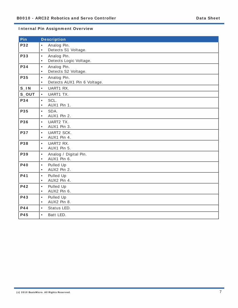
Internal Pin Assignment Overview
Pin DescriptionP32 • Analog Pin.
• Detects S1 Voltage.P33 • Analog Pin.
• Detects Logic Voltage.P34 • Analog Pin.
• Detects S2 Voltage.P35 • Analog Pin.
• Detects AUX1 Pin 6 Voltage.S_IN • UART1 RX.S_OUT • UART1 TX.P34 • SCL.
• AUX1 Pin 1.P35 • SDA.
• AUX1 Pin 2.P36 • UART2 TX.
• AUX1 Pin 3.P37 • UART2 SCK.
• AUX1 Pin 4.P38 • UART2 RX.
• AUX1 Pin 5.P39 • Analog / Digital Pin.
• AUX1 Pin 6.P40 • Pulled Up
• AUX2 Pin 2.P41 • Pulled Up
• AUX2 Pin 4.P42 • Pulled Up
• AUX2 Pin 6.P43 • Pulled Up
• AUX2 Pin 8.P44 • Status LED.
P45 • Batt LED.
(c) 2010 BasicMicro. All Rights Reserved.
B0010 - ARC32 Robotics and Servo Controller Data Sheet
8
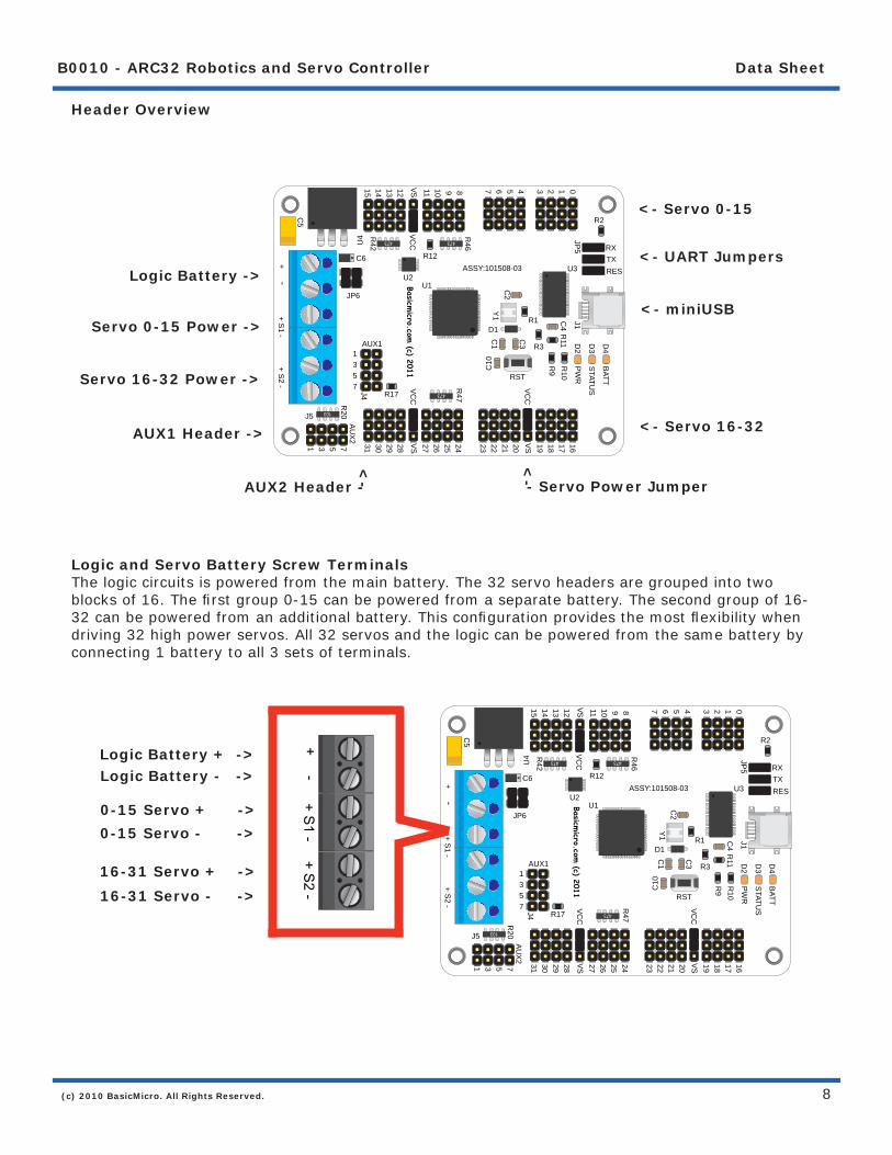
Header Overview
Logic and Servo Battery Screw TerminalsThe logic circuits is powered from the main battery. The 32 servo headers are grouped into two blocks of 16. The fi rst group 0-15 can be powered from a separate battery. The second group of 16-32 can be powered from an additional battery. This confi guration provides the most fl exibility when driving 32 high power servos. All 32 servos and the logic can be powered from the same battery by connecting 1 battery to all 3 sets of terminals.
BATT
D4
D3
D2
C4
C3
C1
C10
R2
U1U2
C6
J5
U4
C5
R12
Y1
C2
R1D1
J1JP
5
U3
R11
STATU
S
PW
R
R10
R9
RST
0123456789101112131415
161718192021222324252627
R46
R42
R20
R47
ASSY:101508-03
VC
CV
SV
CC
VSBasicm
icro.com (c) 2011
7531
+ S1 -
+ S2 -
+ -
28293031
AU
X2
VC
CV
S
JP6
AUX11357
R17J4
RXTXRES
R3
BATT
D4
D3
D2
C4
C3
C1
C10
R2
U1U2
C6
J5
U4
C5
R12
Y1
C2
R1D1
J1JP
5
U3
R11
STATU
S
PW
R
R10
R9
RST
0123456789101112131415
161718192021222324252627
R46
R42
R20
R47
ASSY:101508-03
VC
CV
SV
CC
VSBasicm
icro.com (c) 2011
7531
+ S1 -
+ S2 -
+ -
28293031
AU
X2
VC
CV
S
JP6
AUX11357
R17J4
RXTXRES
R3
Logic Battery ->
Servo 0-15 Power ->
Servo 16-32 Power ->
AUX1 Header ->
<- miniUSB
AUX2 Header -
<-
Logic Battery + ->Logic Battery - ->
<- UART Jumpers
<- Servo 16-32
<- Servo 0-15
+ S1 -
+ S2 -
+ -
16-31 Servo + ->16-31 Servo - ->
0-15 Servo + ->0-15 Servo - ->
- Servo Power Jumper
<-
(c) 2010 BasicMicro. All Rights Reserved.
B0010 - ARC32 Robotics and Servo Controller Data Sheet
9
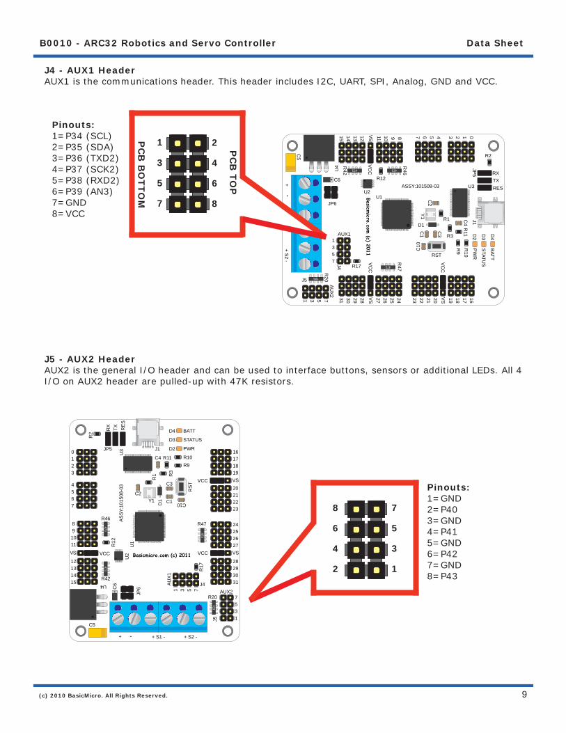
J4 - AUX1 HeaderAUX1 is the communications header. This header includes I2C, UART, SPI, Analog, GND and VCC.
J5 - AUX2 HeaderAUX2 is the general I/O header and can be used to interface buttons, sensors or additional LEDs. All 4 I/O on AUX2 header are pulled-up with 47K resistors.
BATTD4
D3
D2
C4
C3
C1 C10
R2
U1
U2
C6
J5
U4
C5
R12
Y1C2
R1
D1
J1JP5
U3
R11
STATUS
PWR
R10R9
RS
T
0123
4567
891011
12131415
16171819
20212223
24252627
R46
R42
R20
R47
AS
SY:
1015
08-0
3
VCC VSVCCVS Basicmicro.com (c) 2011
7531
+ S1 - + S2 -+ -
28293031
AUX2
VCC VS
JP6
AU
X1
1 3 5 7R
17
J4
RX TX RE
S
R3
BATT
D4
D3
D2
C4
C3
C1
C10
R2
U1U2
C6
J5
U4
C5
R12
Y1
C2
R1D1
J1JP
5
U3
R11
STATU
S
PW
R
R10
R9
RST
0123456789101112131415
161718192021222324252627
R46
R42
R20
R47
ASSY:101508-03
VC
CV
SV
CC
VSBasicm
icro.com (c) 2011
7531
+ S1 -
+ S2 -
+ -
28293031
AU
X2
VC
CV
S
JP6
AUX11357
R17J4
RXTXRES
R3
7
5
3
1
8
6
4
2
PC
B TO
P
PC
B B
OTTO
M
1
3
5
7
2
4
6
8
Pinouts:1=P34 (SCL)2=P35 (SDA)3=P36 (TXD2)4=P37 (SCK2)5=P38 (RXD2)6=P39 (AN3)7=GND8=VCC
Pinouts:1=GND2=P403=GND4=P415=GND6=P427=GND8=P43
(c) 2010 BasicMicro. All Rights Reserved.
B0010 - ARC32 Robotics and Servo Controller Data Sheet
10
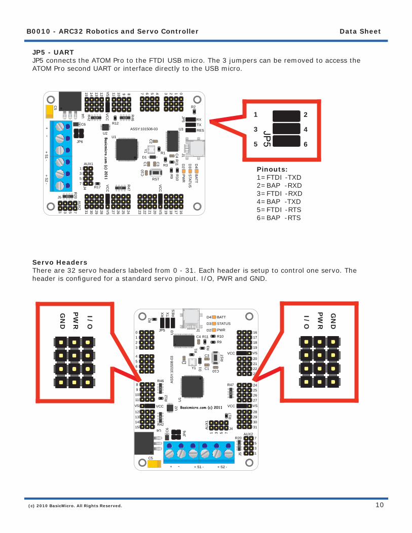
JP5 - UARTJP5 connects the ATOM Pro to the FTDI USB micro. The 3 jumpers can be removed to access the ATOM Pro second UART or interface directly to the USB micro.
Servo HeadersThere are 32 servo headers labeled from 0 - 31. Each header is setup to control one servo. The header is confi gured for a standard servo pinout. I/O, PWR and GND.
BATTD4
D3
D2
C4
C3
C1 C10
R2
U1
U2
C6
J5
U4
C5
R12
Y1C2
R1
D1
J1JP5
U3
R11
STATUS
PWR
R10R9
RS
T
0123
4567
89
1011
12131415
16171819
20212223
24252627
R46
R42
R20
R47
AS
SY:
1015
08-0
3
VCC VSVCCVS Basicmicro.com (c) 2011
7531
+ S1 - + S2 -+ -
28293031
AUX2
VCC VS
JP6
AU
X1
1 3 5 7R
17
J4
RX TX RE
S
R3
BATT
D4
D3
D2
C4
C3
C1
C10
R2
U1U2
C6
J5
U4
C5
R12
Y1
C2
R1D1
J1JP
5
U3
R11
STATU
S
PW
R
R10
R9
RST
0123456789101112131415
161718192021222324252627
R46
R42
R20
R47
ASSY:101508-03
VC
CV
SV
CC
VSBasicm
icro.com (c) 2011
7531
+ S1 -
+ S2 -
+ -
28293031
AU
X2
VC
CV
S
JP6
AUX11357
R17J4
RXTXRES
R3
JP5
1
3
5
2
4
6
Pinouts:1=FTDI -TXD2=BAP -RXD3=FTDI -RXD4=BAP -TXD5=FTDI -RTS6=BAP -RTS
I/O
PW
R
GN
D
I/O
PW
R
GN
D
(c) 2010 BasicMicro. All Rights Reserved.
B0010 - ARC32 Robotics and Servo Controller Data Sheet
11
BATTD4
D3
D2
C4
C3
C1 C10
R2
U1
U2
C6
J5
U4
C5
R12
Y1C2
R1
D1
J1JP5
U3
R11
STATUS
PWR
R10R9
RS
T
0123
4567
891011
12131415
16171819
20212223
24252627
R46
R42
R20
R47
AS
SY:
1015
08-0
3
VCC VSVCCVS Basicmicro.com (c) 2011
7531
+ S1 - + S2 -+ -
28293031
AUX2
VCC VS
JP6
AU
X1
1 3 5 7R
17
J4
RX TX RE
S
R3
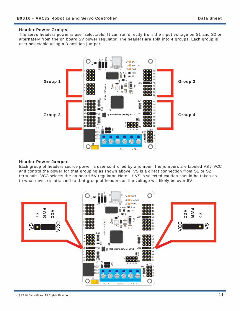
Header Power GroupsThe servo headers power is user selectable. It can run directly from the input voltage on S1 and S2 or alternately from the on board 5V power regulator. The headers are split into 4 groups. Each group is user selectable using a 3 position jumper.
Header Power Jumper Each group of headers source power is user controlled by a jumper. The jumpers are labeled VS / VCC and control the power for that grouping as shown above. VS is a direct connection from S1 or S2 terminals. VCC selects the on board 5V regulator. Note: If VS is selected caution should be taken as to what device is attached to that group of headers as the voltage will likely be over 5V.
VC
C
PW
RS1
VC
C
VS
VC
C
VS
VC
C
PW
R S2
Group 1
Group 2
Group 3
Group 4
BATTD4
D3
D2
C4
C3
C1 C10
R2
U1
U2
C6
J5
U4
C5
R12
Y1C2
R1
D1
J1JP5
U3
R11
STATUS
PWR
R10R9
RS
T
0123
4567
891011
12131415
16171819
20212223
24252627
R46
R42
R20
R47
AS
SY:
1015
08-0
3
VCC VSVCCVS Basicmicro.com (c) 2011
7531
+ S1 - + S2 -+ -
28293031
AUX2
VCC VS
JP6
AU
X1
1 3 5 7R
17
J4
RX TX RE
S
R3
(c) 2010 BasicMicro. All Rights Reserved.
B0010 - ARC32 Robotics and Servo Controller Data Sheet
12
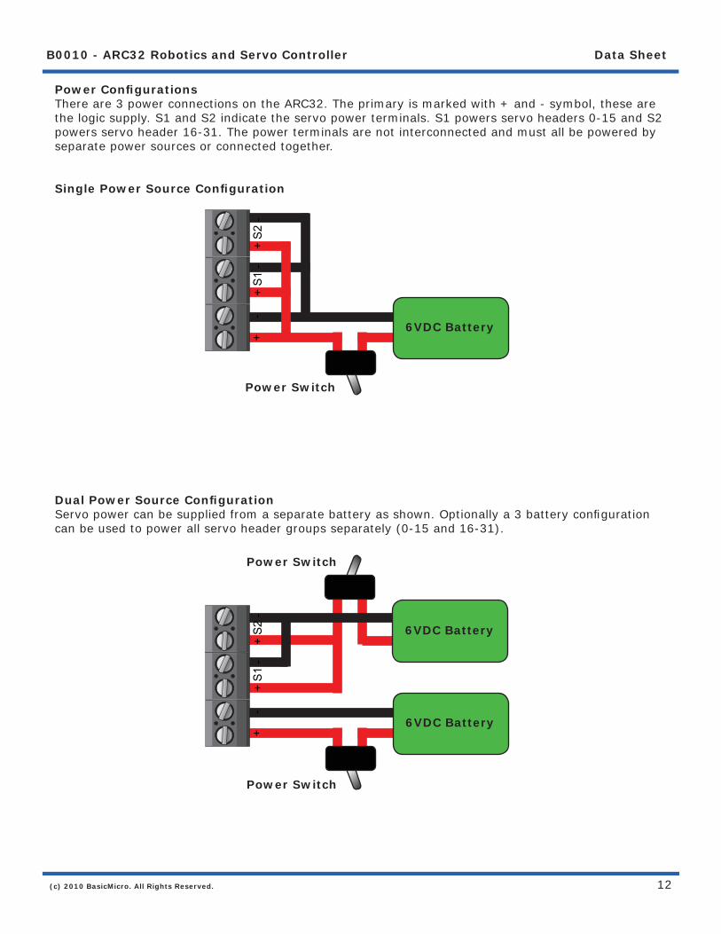
Power Confi gurationsThere are 3 power connections on the ARC32. The primary is marked with + and - symbol, these are the logic supply. S1 and S2 indicate the servo power terminals. S1 powers servo headers 0-15 and S2 powers servo header 16-31. The power terminals are not interconnected and must all be powered by separate power sources or connected together.
Single Power Source Confi guration
Dual Power Source Confi gurationServo power can be supplied from a separate battery as shown. Optionally a 3 battery confi guration can be used to power all servo header groups separately (0-15 and 16-31).
6VDC Battery
Power Switch
+ S
1 -
+ S
2 -
+
-
6VDC Battery
Power Switch
+ S
1 -
+ S
2 -
+
-
6VDC Battery
Power Switch
(c) 2010 BasicMicro. All Rights Reserved.
B0010 - ARC32 Robotics and Servo Controller Data Sheet
13
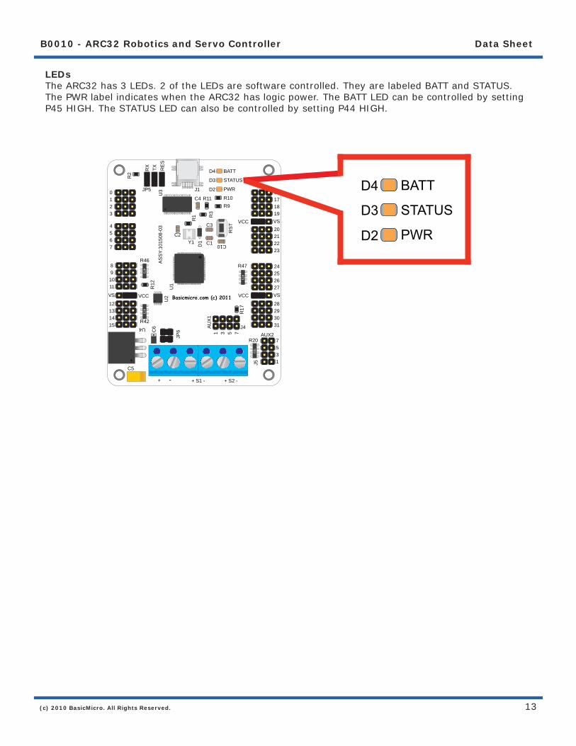
LEDsThe ARC32 has 3 LEDs. 2 of the LEDs are software controlled. They are labeled BATT and STATUS. The PWR label indicates when the ARC32 has logic power. The BATT LED can be controlled by setting P45 HIGH. The STATUS LED can also be controlled by setting P44 HIGH.
BATTD4
D3
D2
C4
C3
C1 C10
R2
U1
U2
C6
J5
U4
C5
R12
Y1C2
R1
D1
J1JP5
U3
R11
STATUS
PWR
R10R9
RS
T
0123
4567
891011
12131415
16171819
20212223
24252627
R46
R42
R20
R47
AS
SY:
1015
08-0
3
VCC VSVCCVS Basicmicro.com (c) 2011
7531
+ S1 - + S2 -+ -
28293031
AUX2
VCC VS
JP6
AU
X1
1 3 5 7R
17
J4
RX TX RE
S
R3
BATTD4
D3
D2
STATUS
PWR

(c) 2010 BasicMicro. All Rights Reserved.
B0010 - ARC32 Robotics and Servo Controller Data Sheet
14
ARC32 Specifi c CommandsThe ARC32 has a unique hardware setup to control all 32 servos in the background with almost no MCU time used. To support this unique feature, several special commands were created. Most of the servo headers are multiplex with additional pins and analog functionality. The following section explains how all the special hardware and servo functionality is accessed.
The servos are controlled using a custom hardware system (HSERVO2) that runs in the background. Servos can not be controlled by any other method. Standard Pulseout or Servo command as shown in the BasicATOM Pro Syntax Manual will not work with the ARC32.
ENABLEHSERVO2To activate the hservo2 system you must use the command ENABLEHSERVO2 at the beginning of your program. ENABLEHSERVO2 instructs the compiler to load the required interrupt driven library during compile time.
HSERVOThe HSERVO command is used to position a servo on any of the 32 headers. HSERVO can be used to update one servo at a time of several servos depending on usage. The following code snippet centers a servo connected to header position 31.
Hservo [P31/0]
Hservo can move a servo incrementally. In the following code snippet the servo will move toward posi-tion 10000 in 100 steps every 20ms. 20ms is the fastest a standard servos position can be updated.
Hservo [P31\10000\100]
Hservo can move more than one servo at a time. The following code snippet will move 3 servos to their center positions. The servos are connected to headers 1,2 and 3.
Hservo [P1\0, P2\0, P3\0]
HSERVOWAITHSERVO is a background task. If the optional speed value is used the program will continue to run while HSERVO is executing in the background. To halt the program until the given position value is reached, HSERVOWAIT can be used. The following code snippet will wait until HSERVO has reach 10000 in increments of 100 before continuing program execution.
Hservo [P31\10000\100]HSERVOWAIT [P31]
(c) 2010 BasicMicro. All Rights Reserved.
B0010 - ARC32 Robotics and Servo Controller Data Sheet
15
HSERVOPOSAll 32 servo position values are stored. HSERVOPOS is used to retrieve the current position value for a particular servo. If a speed value was used HSERVOPOS will return the current position being executed not the total position value used. The following code snippet will conditional execute a group on com-mands until 10000 is reached.
ENABLEHSERVO2
HSERVO [P31\10000\100] while(hservopos(P31)<>10000) ;loop until the servo reaches 10000 ;do stuff here wend
HSERVOIDLETo determine if a servo is idle without knowing the last position specifi ed HSERVOIDLE can be used. HSERVOIDLE will return a 0 value if the servo is not idle. A servo not currently moving would return a value of 0. If the servo is still moving a value other than 0 is returned. This would be the case if the optional speed value is set and the servo is active. The following code snippet will execute a group of commands until the servo is idle.
ENABLEHSERVO2
HSERVO [P31\10000\100] while(hservoidle(P31)=0) ;loop until the servo becomes idle ;do stuff here wend
HSERVOSTATEThe servo headers pins can be read. Several of the pins are analog capable. HSERVOSTATE will return the state or analog value of a given pin. If a pin is not analog HSERVOSTATE will return a 0 for a low and 1023 for a high signal. Otherwise a value of 0 to 1023 is return which represents the voltage ap-plied to the read pin. The following example program will read the analog value from header 8 which is analog capable and print the results to a terminal window.
ENABLEHSERVO2
Result Var Byte
Main Volts = HSERVOSTATE P8 serout s_out, i19200, [DEC Result]Goto Main

(c) 2010 BasicMicro. All Rights Reserved.
B0010 - ARC32 Robotics and Servo Controller Data Sheet
16
HSERVOTIMEThe ARC32 has a built in 64 bit timer that counts in clock cycles from power up. The timer is cleared after every reset or power cycle. The returned timer value is 32bits. The bits can be shifted to control the resolution of the value returned. The following code snippet will read the time and blink the status led on the ARC32 every half second.
ENABLEHSERVO2
starttime var longstoptime var longmain starttime = hservotime 0 ;get current time do stoptime = (hservotime 0)-starttime while stoptime < 10000000 toggle p44 goto main
Voltaqe Level DetectionThe ARC 32 is capable of detecting the voltage level on all three power inputs. The voltages are read using the HSERVOSTATE command. The command will return an analog value from 0 to 1023. The analogs pins are accessed by using there pin names. P33 will return the logic voltage. P32 returns S1 voltage. P34 returns S2 voltage. The following code snippet will read the logic voltage level and display it to the terminal window.
ENABLEHSERVO2
Volts Var Byte
Main Volts = HSERVOSTATE P33 serout s_out, i19200, [REAL (TOFLOAT Volts/51.2)\2]Goto Main
Analog PinsAll analog capable pins list in the pin overview charts are read with HSERVOSTATE which will return the value of any analog capable pin. The returned value will be 0 to 1023. The following code snippet will return the analog value and store the result in a variable. Any analog capable pin can be read by changing the pin number.
ENABLEHSERVO2 Temp = HSERVOSTATE P8

(c) 2010 BasicMicro. All Rights Reserved.
B0010 - ARC32 Robotics and Servo Controller Data Sheet
17
ARC32 Servo ExampleThe sample program will loop through all 32 servo headers moving each connected servo through its full swing. If connected to a terminal window all voltage inputs S1, S2 and logic will be displayed.
;Basic Micro ARC32 test code. Set terminal window to 9600 baud.
ENABLEHSERVO2
ENABLEHSERIALSetHSerial H9600,H8DATABITS,HNOPARITY,H1STOPBITS
servopin var bytefor servopin = 0 to 31 hservo [servopin\0] ;default all servos to center positionnext
pause 1000
main for servopin = 0 to 31 hserout [0,” Moving servo: “,dec servopin,13,13] hserout [“VS1 voltage is: “,real (TOFLOAT hservostate 32)/1024.0*20.0\2,”v”,13] hserout [“VL voltage is: “,real (TOFLOAT hservostate 33)/1024.0*20.0\2,”v”,13] hserout [“VS2 voltage is: “,real (TOFLOAT hservostate 34)/1024.0*20.0\2,”v”,13] if(hservostate 33 < 281)then hserout [“Battery voltage is low!”] high p45 ;turn battery warnign LED on else low p45 endif
hservo [servopin\-5000\100] ;move to -5000 position in 1 second while(hservoidle(servopin)=0) toggle p44 pause 100 wend
hservo [servopin\5000\100] ;move from -5000 to 5000 position in 2 seconds while(hservoidle(servopin)=0) toggle p44 pause 100 wend
hservo [servopin\0\100] ;move to 0 position in 1 second while(hservoidle(servopin)=0) toggle p44 pause 100 wend low p44 pause 500 next goto main

(c) 2010 BasicMicro. All Rights Reserved.
B0010 - ARC32 Robotics and Servo Controller Data Sheet
18
Electrical Characteristics
Characteristic Rating Min MaxLogic Regulator Input Voltage VDC 6 12S1 / S2 Input Range VDC 0 12Current Draw mA 100 10AI/O Voltages VDC 0 5Tempature Range C -40 +125

(c) 2010 BasicMicro. All Rights Reserved.
B0010 - ARC32 Robotics and Servo Controller Data Sheet
19
WarrantyBasic Micro warranties its products against defects in material and workmanship for a period of 90 days. If a defect is discovered, Basic Micro will, at our discretion, repair, replace, or refund the pur-chase price of the product in question. Contact us at [email protected]. No returns will be accepted without the proper authorization.
Copyrights and TrademarksCopyright© 2010 by Basic Micro, Inc. All rights reserved. PICmicro® is a trademark of Microchip Technology, Inc. The Basic Atom and Basic Micro are registered trademarks of Basic Micro Inc. Other trademarks mentioned are registered trademarks of their respective holders.
Disclaimer Basic Micro cannot be held responsible for any incidental, or consequential damages resulting from use of products manufactured or sold by Basic Micro or its distributors. No products from Basic Micro should be used in any medical devices and/or medical situations. No product should be used in a life support situation.
Contacts Email: [email protected] Tech support: [email protected] Web: http://www.basicmicro.com
Discussion ListA web based discussion board is maintained at http://www.basicmicro.com.
Technical SupportTechnical support is made available by sending an email to [email protected]. All email will be answered within 48 hours. All general syntax and programming questions, unless deemed to be a software issue, will be referred to the on-line discussion forums.