B. Pneumatic Slug Test Procedures - EPOC - Home Test... · B. Pneumatic Slug Test Procedures Wes...
36
B. Pneumatic Slug Test Procedures Wes McCall, Geologist KS28 Geoprobe Systems ([email protected]) Wichita, KS
Transcript of B. Pneumatic Slug Test Procedures - EPOC - Home Test... · B. Pneumatic Slug Test Procedures Wes...

B. Pneumatic Slug Test Procedures
Wes McCall,
Geologist KS28
Geoprobe Systems
Wichita, KS

Why Do You Want to Know K ?
• Contaminant Migration Pathways
• Risk Based Corrective Actions
• Monitored Natural Attenuation
• Design Remediation Systems
• Injection of Fluids
K = Important Physical Parameter

Conventional “Mechanical” Slug Test
SWL Falling
Head
Test
Rising
Head
Test
Slug-in
Test Slug-out
Test
Flow out Flow in
Valve
Closed
Valve
Open
Valve
Closed
Rising
Head
Test
Water
Level
Rises
Flow in Flow out
Valve
Open
Air In
Air Out
Transducer
A Pneumatic Slug Test
Water
Level
Falls
Eq
uil
ibri
um

Pneumatic Slug Test
Well Diameter Limits ? 4” well
20ft screen
SP16 (5/8” ID)
1ft screen
Keep release valve ID ≥ Well ID to
prevent noise & interference
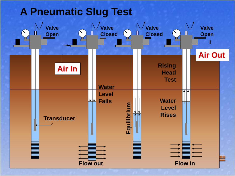
DP Field Methods to Access Groundwater
Temporary Installations
•Single Tube, Exposed Screen
• Single Tube, Protected Screen
• Dual Tube Profiling
Long Term Installations
• DP Monitoring Wells
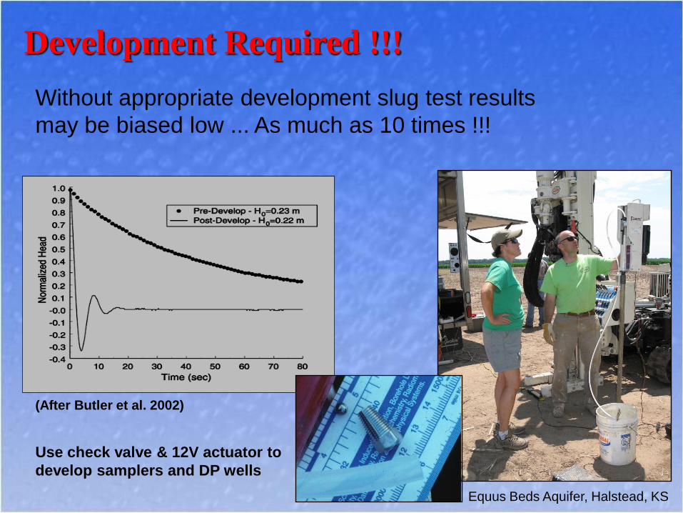
Development Required !!!
Without appropriate development slug test results
may be biased low ... As much as 10 times !!!
Use check valve & 12V actuator to
develop samplers and DP wells
Equus Beds Aquifer, Halstead, KS
(After Butler et al. 2002)

Pneumatic Slug Test System :
GW1600
Kit weighs ~ 30 lbs

Components of the Pneumatic Slug Test System
A) Pneumatic Manifold
B) Adapters for Rods &
Casing
C) O-rings – use on
each rod joint *
(A)
(B)
(C)

Components …
A) A to D
Converter
(logger)
[1, 2, 10 & 38 Hz]
B) Transducer
10 psi with
100ft cable
C) Power & Data
Cables
(A)
(B)
(C)
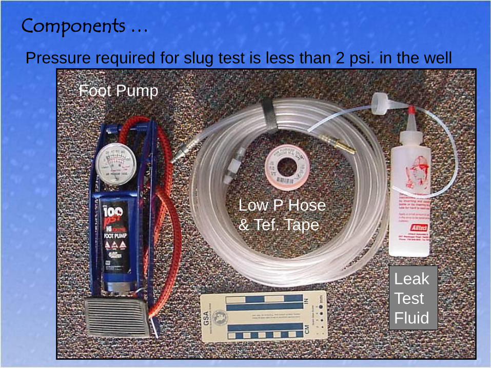
Components …
Foot Pump
Low P Hose
& Tef. Tape
Leak
Test
Fluid
Pressure required for slug test is less than 2 psi. in the well
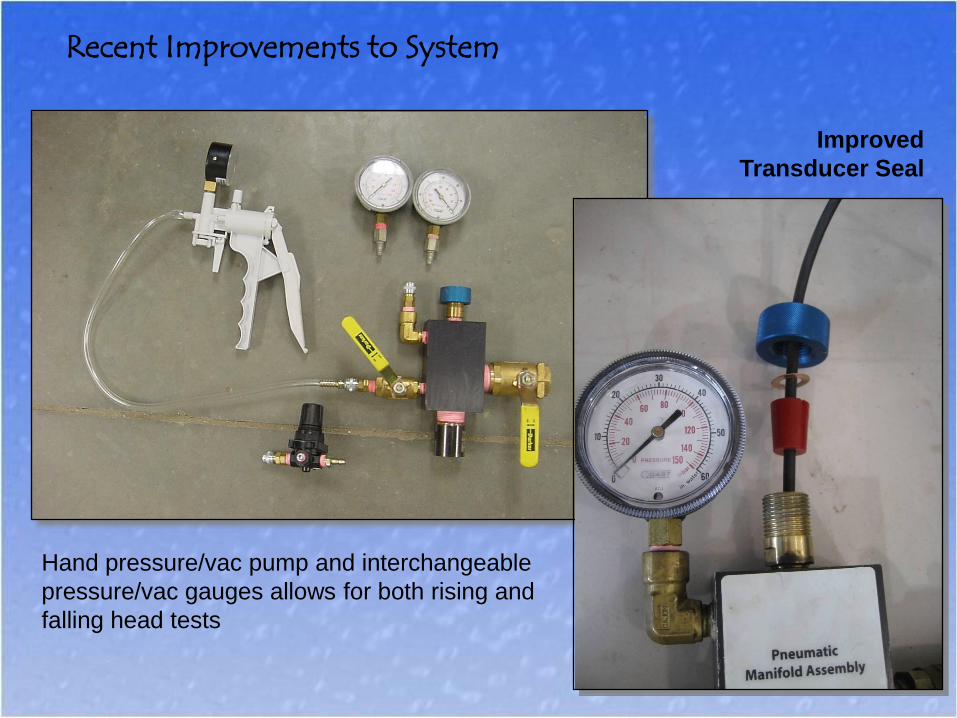
Recent Improvements to System
Hand pressure/vac pump and interchangeable
pressure/vac gauges allows for both rising and
falling head tests
Improved
Transducer Seal

Pressure and Vacuum Gauges
Graduated in inches and centimeters of water pressure.
Record this information for Ho data.
Not psi !
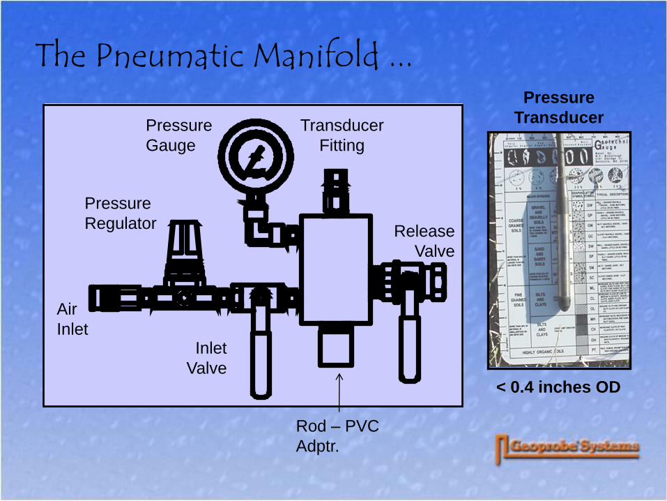
The Pneumatic Manifold ...
Pressure
Regulator
Pressure
Gauge
Air
Inlet Inlet
Valve
Rod – PVC
Adptr.
Transducer
Fitting
Release
Valve
Pressure
Transducer
< 0.4 inches OD

Data Acq.
Tra
nsducer
Pneumatic Head
Scre
en
Field Set Up for Pneumatic Slug Testing
• Install Sampler
• Set Screen & Develop
• Attach Pneumatic Manifold
• Insert Transducer
• Initiate Software
• Conduct Slug Test
Screen Must be Saturated
for pneumatic testing
Solar heating of cable
¾” DP Wells, Clarks, NE

Pneumatic Head
1.5-inch Release Valve
1.5-inch ID x 2.25-inch OD Rods
Transducer
3/4-inch 10-slot PVC Screen
Dual-tube Method for K-Profiling
Screen can be
removed and
re-installed at
multiple depths
to allow for
vertical
profiling of
hydraulic
conductivity
Pre-core for low-K / fine grained materials

Adapters for PVC Wells
2-inch and 4-inch adapters
shown, others available

Questions ?
Comet Reflection
Kansas Farm Pond
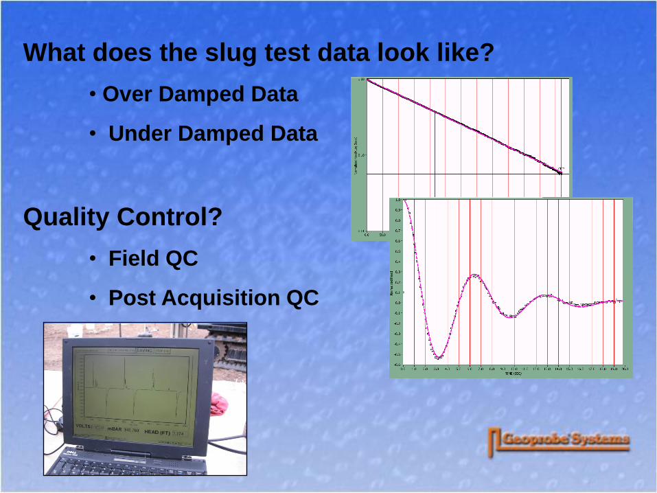
What does the slug test data look like?
• Over Damped Data
• Under Damped Data
Quality Control?
• Field QC
• Post Acquisition QC
1.5
2
2.5
3
3.5
0 50 100 150 200
Time (seconds)
Head
(fe
et
of
wate
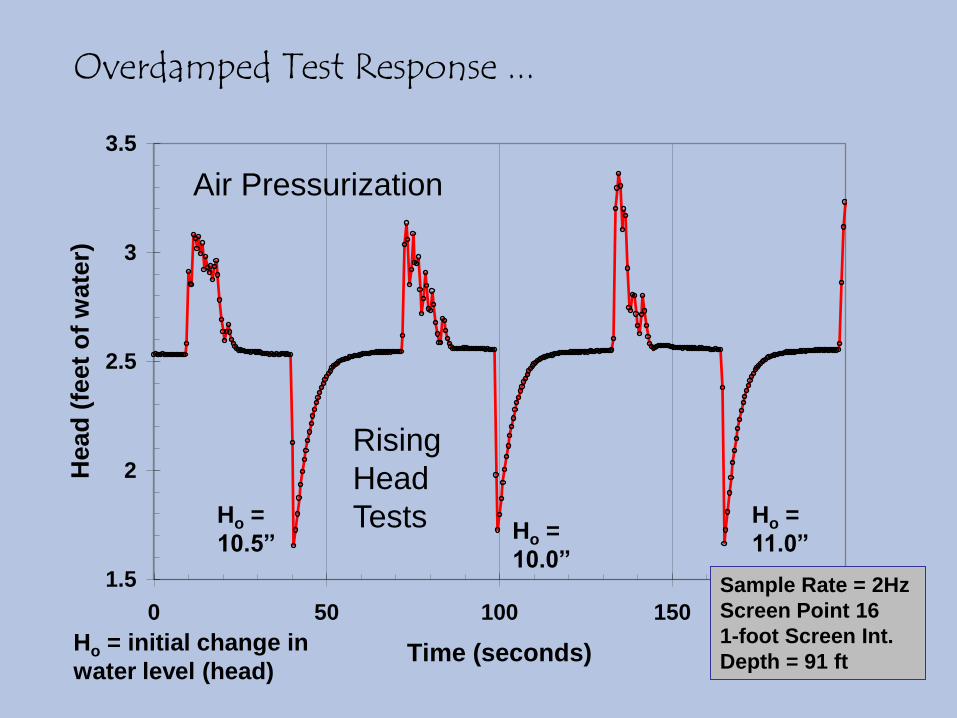
r)Overdamped Test Response ...
Air Pressurization
Rising
Head
Tests Ho =
10.5” Ho =
10.0”
Ho =
11.0”
Ho = initial change in
water level (head)
Sample Rate = 2Hz
Screen Point 16
1-foot Screen Int.
Depth = 91 ft
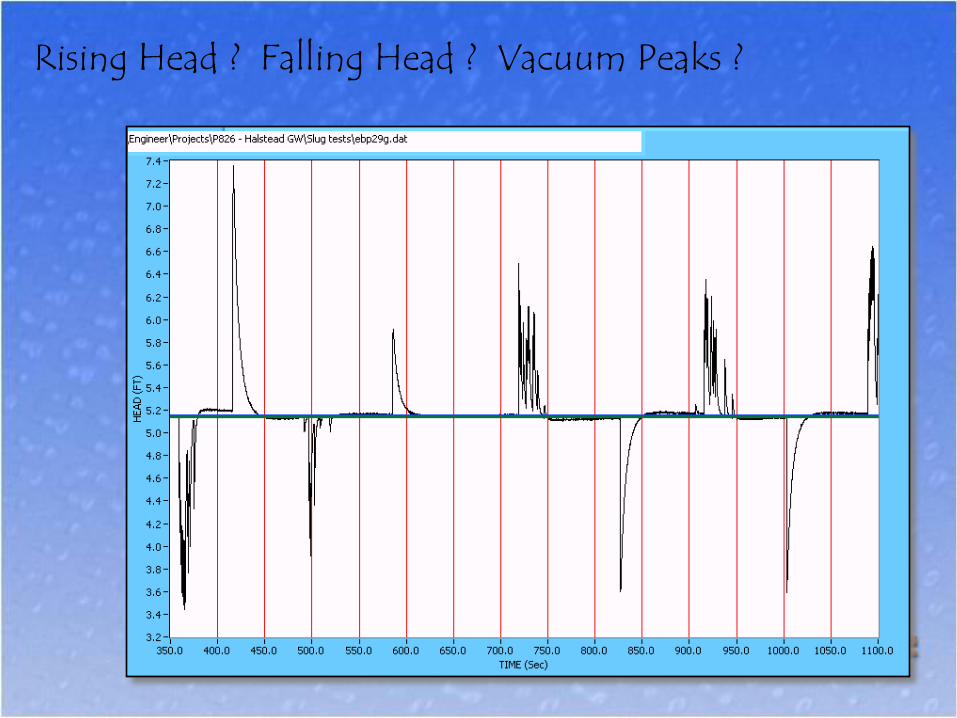
Rising Head ? Falling Head ? Vacuum Peaks ?

Raw Data Plot
PW07D file g
1.8
2
2.2
2.4
2.6
2.8
3
75 100 125 150 175 200 225 250 275
Time (seconds)
Head
(ft
of
wate
r)
Underdamped Test Response ...
Air Pressurization
Slug Test
Ho = 6.0”
Slug Test
Ho = 5.6”
DP installed PP well
Nominal ½” PVC
9-ft screen interval
Depth 65ft
Water level 25ft
Why not model this?
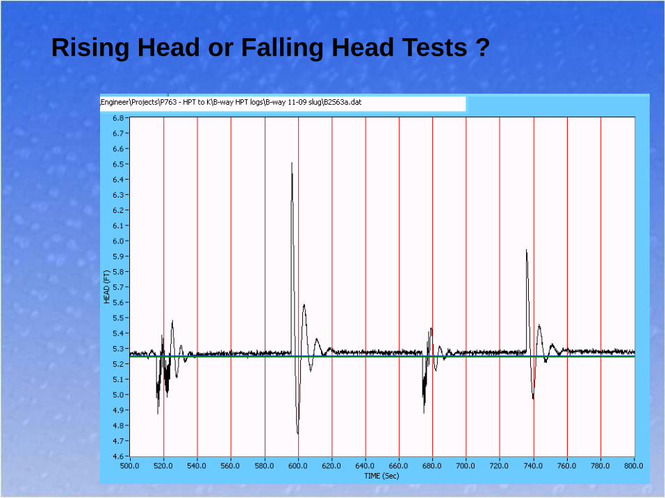
Rising Head or Falling Head Tests ?

Slug Test Field QC : Visual Check
Three slug tests with
~same Ho (e.g. 2ft)
• Compare peak height
• Curve symmetry
• Recovery time same

Two additional slug
tests with larger &
smaller Ho
• Are peak heights
proportional
• Curve symmetry
• Recovery time same
• Post Acquisition QC
Ho = 20.1 20.1”
30.4”
5.0”
10.4”
Field QC (cont.)
Is Calculated K independent of Ho ?
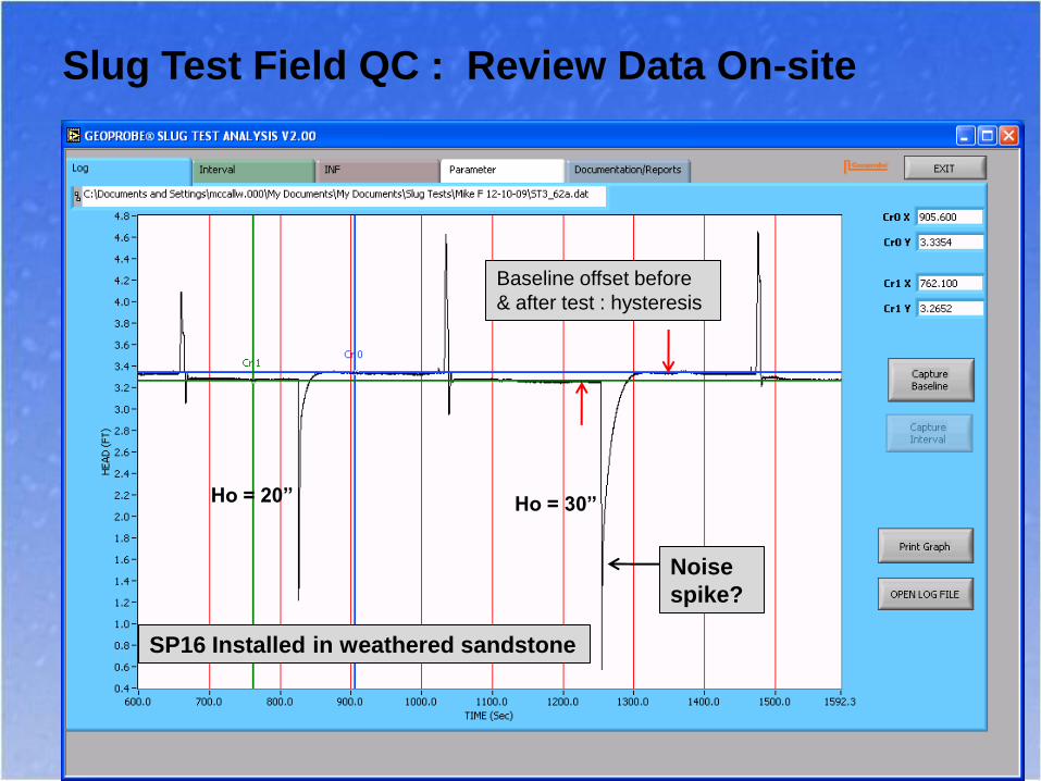
Slug Test Field QC : Review Data On-site
Baseline offset before
& after test : hysteresis
Noise
spike?
SP16 Installed in weathered sandstone
Ho = 20” Ho = 30”

Slug Test Field QC : Review Data On-site
Noise?
Inflection point ?
Change in slope ?

Slug Test Field QC (cont.)
Fast early time recovery, higher slope
Software Model Fit ?

Slug Test Field QC (cont.)
“Double Straight Line Effect”
• More development?
• Bad well construction?
• Correct model ?

Field QC : What is wrong with this test ?

PW07D Pneumatic Slug Test
Different Initial Head Values
-0.6
-0.3
0.0
0.3
0.6
0.9
1.2
1.5
0 5 10 15 20
Time (seconds)
He
ad
(ft
of
wa
ter)
Initial Head: 10"
Initial Head: 18"
Initial Head: 5.0"
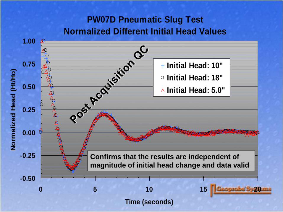
PW07D Pneumatic Slug Test
Normalized Different Initial Head Values
-0.50
-0.25
0.00
0.25
0.50
0.75
1.00
0 5 10 15 20
Time (seconds)
No
rma
lize
d H
ea
d (
Ht/
Ho
) Initial Head: 10"
Initial Head: 18"
Initial Head: 5.0"
Confirms that the results are independent of
magnitude of initial head change and data valid

Curve Matching of Field Data
High-K Slug Test Analysis
-0.50
-0.25
0.00
0.25
0.50
0.75
1.00
0 5 10 15 20 25 30
Dimensionless Time
No
rma
lize
d H
ea
d (
Ht/
Ho
)
0.52
Modulus 1.1
C d
SP07D, 1ft Screen, 60ft deep
Pneumatic Slug Test
18 inches of water displaced
K = 94.3 ft/day (3.33E-2 cm/sec)K = 94.3 ft/day (3.33E-2 cm/sec)

Why Use Direct Push Methods to
Conduct Slug Tests ?
Location ... Location … Location
Depth / Profiles
Screen Interval
Cost, NO Permanent Wells
Efficient ... While sampling !
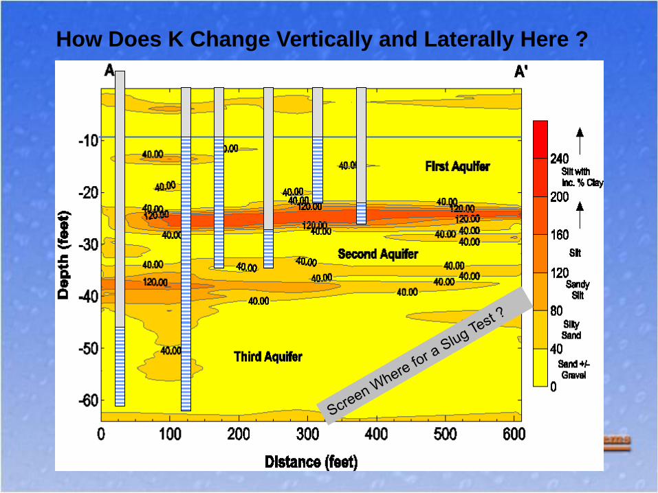
How Does K Change Vertically and Laterally Here ?

Questions ?
Cache La Poudre River
Northern Colorado