AZTEC gold 222535 master - Boiler Manuals Gold.pdf · The Aztec Gold is a wall-mounted electric...
22
TRIANCO KM 59690 Electric System Boiler To be retained by the householder FITTING, OPERATION, INSTALLATION & SERVICING INSTRUCTIONS
Transcript of AZTEC gold 222535 master - Boiler Manuals Gold.pdf · The Aztec Gold is a wall-mounted electric...

TRIANCO
KM 59690
Electric System Boiler
To be retained by the householder
FITTING, OPERATION, INSTALLATION & SERVICING
INSTRUCTIONS

2
Notes:
(a) Electrical safety checks should be carried out by a competent person.
(b) It is a requirement of the guarantee and any extended warranty that an annual service is carried out by a competent person.
Installation Engineer’s Signature ................................................................................................................................
Company Name (if applicable) ................................................................................................................................
Company Address: ................................................................................................................................
................................................................................................................................
................................................................................................................................
Company Tel. No: ................................................................................................................................
HEALTH AND SAFETY
INFORMATION FOR THE INSTALLER AND SERVICE ENGINEERS
Under the Consumer Protection Act 1987 and the Health and Safety at Work Act 1974, it is arequirement to provide information on substances hazardous to health (COSHH Regulations1988).
The Company takes every reasonable care to ensure that these products are designed and constructed to meet these general safety requirements, when properly used and installed.
To fulfil this requirement products are comprehensively tested and examined before despatch.
This appliance may contain some of the items below.
When working on the appliance it is the responsibility of the user/engineer to ensure that any necessary personal protective clothing or equipment is worn appropriate to parts that could beconsidered as being hazardous to health and safety.
INSULATION AND SEALS
Mineral fibre insulation is used on this appliance.
May be harmful if inhaled. May be irritating to the skin, eyes, nose or throat. When handling avoidinhalation and contact with eyes. Use (disposable) gloves, face masks and eye protection.
After handling wash hands and other exposed parts. When disposing, reduce dust with waterspray, ensure parts are securely wrapped.
GLUES, SEALANTS & PAINT
Glues and sealants are used in the product and present no known hazards when used in themanner for which they are intended.
PACKAGING
Materials used for the packaging of this appliance are of a recyclable nature.
Warning: plastic bags can cause suffocation. Keep out of reach of children.

Please read these instructions fully before installing this appliance. If in doubt, seek expert advice.
These instructions should be kept in a place close to the appliance for easy reference.
CONTENTS
BASIC FITTING INSTRUCTIONS 4
Preparation and Siting 4/5
Ventilation 4
Clearances and Access 4
Water System 6
Electrical Supply 6
Wiring Diagrams 6/7
Filling the System 8/9
Underfloor Heating Systems 10
OPERATING INSTRUCTIONS 11
Introduction 11
Boiler Controls 11
Indicator Lights 11
Safety Controls 11
External Controls 11
Cleaning & Maintenance 11
Simple Fault-Finding 12
TECHNICAL SPECIFICATION 12
INSTALLATION NOTES 13
Regulations & Safety 13
Declaration of Conformity 13
Boiler Schematic 14
Boiler Components 15
SERVICE 16
After-Sales Service Information 16
Engineer's Fault-Finding 17
Servicing 18
Parts Replacement 18/19/20
Spares List 21
4
PREPARATION & SITING
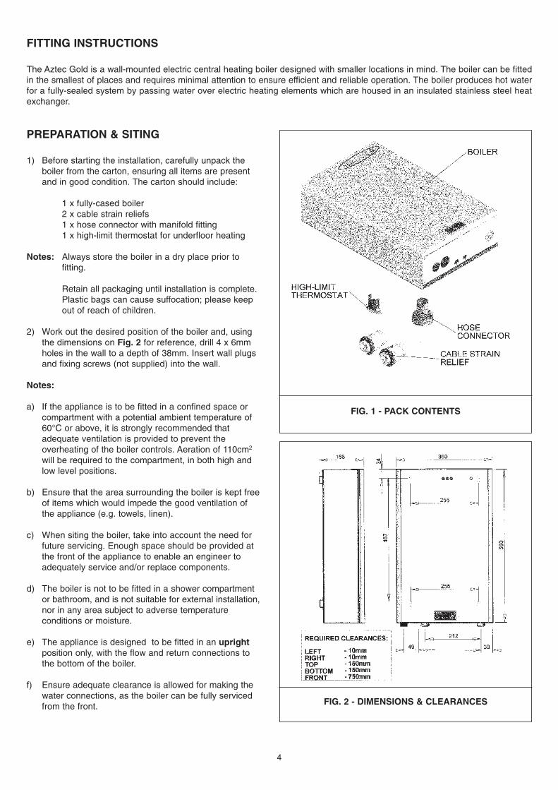
1) Before starting the installation, carefully unpack the boiler from the carton, ensuring all items are present and in good condition. The carton should include:
1 x fully-cased boiler2 x cable strain reliefs1 x hose connector with manifold fitting1 x high-limit thermostat for underfloor heating
Notes: Always store the boiler in a dry place prior to fitting.
Retain all packaging until installation is complete. Plastic bags can cause suffocation; please keep out of reach of children.
2) Work out the desired position of the boiler and, using the dimensions on Fig. 2 for reference, drill 4 x 6mm holes in the wall to a depth of 38mm. Insert wall plugs and fixing screws (not supplied) into the wall.
Notes:
a) If the appliance is to be fitted in a confined space or compartment with a potential ambient temperature of 60°C or above, it is strongly recommended that adequate ventilation is provided to prevent the overheating of the boiler controls. Aeration of 110cm2
will be required to the compartment, in both high and low level positions.
b) Ensure that the area surrounding the boiler is kept freeof items which would impede the good ventilation of the appliance (e.g. towels, linen).
c) When siting the boiler, take into account the need for future servicing. Enough space should be provided at the front of the appliance to enable an engineer to adequately service and/or replace components.
d) The boiler is not to be fitted in a shower compartment or bathroom, and is not suitable for external installation,nor in any area subject to adverse temperature conditions or moisture.
e) The appliance is designed to be fitted in an uprightposition only, with the flow and return connections to the bottom of the boiler.
f) Ensure adequate clearance is allowed for making the water connections, as the boiler can be fully serviced from the front.
FITTING INSTRUCTIONS
The Aztec Gold is a wall-mounted electric central heating boiler designed with smaller locations in mind. The boiler can be fittedin the smallest of places and requires minimal attention to ensure efficient and reliable operation. The boiler produces hot waterfor a fully-sealed system by passing water over electric heating elements which are housed in an insulated stainless steel heatexchanger.
FIG. 1 - PACK CONTENTS
FIG. 2 - DIMENSIONS & CLEARANCES

FITTING INSTRUCTIONS (cont.)
3) Removing the front panel beforehand, hang the boiler onto the screws in the wall, ensuring that all4 keyhole fixing slots are utilised. Tighten screws to ensure a secure fixing.
4) Fit the 2 x cable strain reliefs into the base of the boiler.
5) Install the heating system (radiator/towel rails, etc)in the desired positions as per the manufacturer's instructions. A drain cock must be fitted at the lowest part of the system for ease of drainage. See Fig. 4 for a typical system layout.
IMPORTANTWhile the Aztec Gold is entirely suitable for use onheating systems which utilise plastic pipework, thefirst 100mm from the boiler manifold must alwaysbe 15mm copper.
5
FIG. 3 - STRAIN RELIEF FIXING

FITTING INSTRUCTIONS (cont.)
WATER SYSTEM
Connect the flow and return pipework from theradiator(s) into the corresponding fittings on the boilermanifold. Ensure all fittings are made water-tight.
Notes:
a) The pressure relief valve must be piped to a permanent drain-off on the outside of the building. The drain must not discharge abovean entrance, window, or any public access area. It should be clear of any electrical fittings, and positioned so that any discharge can be clearly seen. The terminating point of the drain-off should be bent down at an angleof 90°.
b) It is recommended that isolation valves are fitted to the pipework. A bypass, as shown in Fig. 4, must be fitted if TRVs are used on theradiators.
c) The flow and return connections are made to the boiler by 2 x 15mm compression fittings.
ELECTRICITY SUPPLY
First isolating the electricity, pass the electrical supplycables and any external control cables through thecable strain reliefs in the base of the boiler, and wiresecurely into the terminal block. The terminal block is located within the casings at the top left-hand side ofthe boiler.
Notes:
a) This appliance must be earthed.
b) It is recommended the boiler is fitted with an external control, such as a room thermostat or programmer.
c) If the water in the system is to be subject to freezing conditions during the pipework run, the appliance should be fitted with a frost thermostat. This will activate the boiler shouldthe temperature fall to a level which could damage the installation.
d) Incoming mains and controls cables should not be routed close to heating pipes.
e) The diagrams opposite are for reference only.Refer to manufacturer's instructions for specific fitting instructions for the room thermostat or programmer.
f) It is recommended that the boiler is wired via a 13 amp RCD plug or switched fused spur.
g) Remove the link wire between terminals 3 & 5 when fitting any external controls.
6
FIG. 5 - BOILER CONNECTION MANIFOLD, SHOWINGPRESSURE RELIEF VALVE, WATER CONNECTIONS AND
PRESSURE GAUGE
FIG. 6 - WIRING FOR EXTERNAL PROGRAMMER & ROOMTHERMOSTAT
Important Note:Before installation, please ensure that the supply
voltage to the appliance is above 207v. If the voltagedrops below this level, a temporary boiler malfunction
may result.

FITTING INSTRUCTIONS (cont.)
ELECTRICAL SUPPLY (cont.)
7
FIG. 9 - INTERNAL WIRING DIAGRAMFIG. 9 - INTERNAL WIRING DIAGRAM
FIG. 7 - WIRING FOR PROGRAMMABLE ROOMTHERMOSTAT
FIG. 8 - WIRING FOR EXTERNAL PROGRAMMER, ROOMTHERMOSTAT & FROST THERMOSTAT

FITTING INSTRUCTIONS (cont.)
FILLING THE SYSTEM
A filling point connection is provided on the front face ofthe boiler manifold to facilitate the initial filling andpressurising of the system via a hose connection(supplied). Alternatively, a permanent filling-loop may beemployed.
Notes:
a) Before filling, ensure that all fittings and joints have been made.
b) Thoroughly flush out the system to remove any swarf and residue from the pipework and radiator(s).
c) There must be no permanent connection between the boiler and the mains water supply.
Filling Method 1: Temporary Hose (Figs. 10/11)
1) Connect a hose to the fill point on the manifold using the fittings supplied.
2) Connect the other end of the hose to the mains water supply, ensuring that all safety valves are fitted in the run (Fig. 11) to prevent system water entering the mains supply. Approved hose unions should be used on all connections.
3) Open the fill point on the manifold (Fig. 10) by turning the isolating knob anti-clockwise.
4) Ensure all isolation valves to the system are open, that the bypass valve is closed, and that the automatic air vent contained within the boiler casings is open (turn the black cap on the device fully anti-clockwise).
5) Switch on the mains supply to the boiler and test the pressure relief valve by continuing to fill until this device activates and releases water into the drain.
6) Switch off the mains water supply.
7) Using the pressure gauge on the front face of the manifold for reference, reduce the water content of the system until the pressure is indicated as 1.5 bar.
8) Thoroughly vent all parts of the system of air and, if necessary, readjust pressure back to 1.5 bar.
9) Close off the fill connection on the manifold, remove the hose and close the automatic air vent.
10) Check all joints are water-tight before operating the appliance.
8
FIG. 10 - FILL POINT
FIG. 11 - FILLING METHOD 1
FITTING INSTRUCTIONS (cont.)
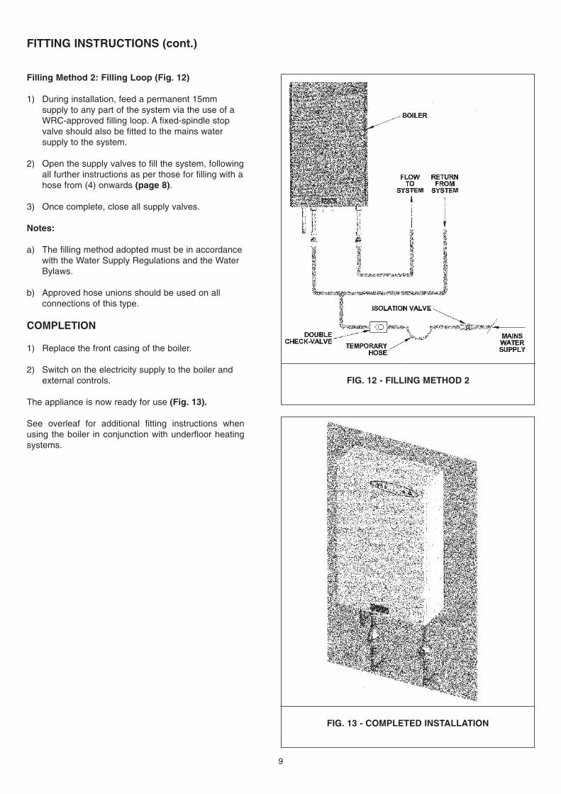
Filling Method 2: Filling Loop (Fig. 12)
1) During installation, feed a permanent 15mm supply to any part of the system via the use of a WRC-approved filling loop. A fixed-spindle stop valve should also be fitted to the mains water supply to the system.
2) Open the supply valves to fill the system, followingall further instructions as per those for filling with ahose from (4) onwards (page 8).
3) Once complete, close all supply valves.
Notes:
a) The filling method adopted must be in accordancewith the Water Supply Regulations and the Water Bylaws.
b) Approved hose unions should be used on all connections of this type.
COMPLETION
1) Replace the front casing of the boiler.
2) Switch on the electricity supply to the boiler and external controls.
The appliance is now ready for use (Fig. 13).
See overleaf for additional fitting instructions whenusing the boiler in conjunction with underfloor heatingsystems.
9
FIG. 12 - FILLING METHOD 2
FIG. 13 - COMPLETED INSTALLATION

FIG. 14 - CONTROL KNOB
When installed on an underfloor heating system withoutthe use of a mixing valve, the following instructions mustbe adhered to.
IMPORTANT NOTE: Ensure the mains supply to theboiler is disconnected before carrying out any work.
1) Replace the safety high-limit thermostat with the alternative stat provided within the literature pack (Fig. 15). See page 19 for more detailed instructions on how to replace high-limit thermostat.
2) Using the white control knob on the front of the PCB controller, the temperature must be set to its lowest setting (30°C) before initial firing.
Important: The temperature should only be subsequently increased in accordance with underfloor heating manufacturer's instructions and BS EN 1264-4.
3) After the temperature has been adjusted to the preferred level, it may be useful to remove the control knob from the PCB controller to prevent further modification. Carefully pull the knob from the PCB, ensuring its mooring is held securely in position (Fig. 14).
Notes:
a) The factory-fitted safety high-limit thermostat is set at 100°C, and is suitable for use with radiator heating systems. The additional high-limit thermostat, for exclusive use with underfloor heating systems, is set at 60°C and must be fitted. Failure to do so will result in damage to the floor surfaces.
b) If the high-limit thermostat operates often, the temperature may be set too high. It is essential that the temperature is not set to above 50°C(refer to Fig. 14 for temperature settings).
c) The pump fitted to this appliance is suitable for a
Ø 15mm plastic pipework run of up to 100m in length. Pipework runs greater than this will require the fitting of an additional pump.
d) Fit the underfloor heating system in accordance with manufacturer's instructions. Trianco cannot accept any responsibility for breakdowns or damage caused by incorrectly-fitted systems.
10
CONTROL KNOB SETTINGS
FIG. 15 HIGH LIMIT THERMOSTAT REPLACEMENT
1 - ISOLATE ELECTRICAL SUPPLY2 - REMOVE THE BOILER FRONT CASING3 - REMOVE CABLES FROM HIGH LIMIT STAT4 - LOOSEN 2 X RETAINING CLIPS5 - REMOVE THERMOSTAT & REPLACE IN REVERSE
ORDER
ADDITIONAL FITTING INSTRUCTIONS - UNDERFLOOR HEATING SYSTEMS

OPERATING INSTRUCTIONS
The Trianco Aztec Gold boiler has been designed andconstructed to give years of trouble-free service and theseinstructions are provided to assist you in obtaining the bestperformance with the least trouble and cost.
The boiler is fully automatic in operation and requires littleattention, other than the setting of any external systemcontrols such as a room thermostat or programmer.
BOILER CONTROLS
Before initial firing of the boiler, ensure that the system is fullof water and the isolation valves (other than the bypass) arefully open. Do not attempt to switch on the boiler if thereis any possibility that the system water is frozen.
1) Check that the time-switch/programmer is ON and that the room thermostat is calling for heat.
2) Switch on the electrical supply to the boiler. After a few seconds the green light should illuminate, followed by the amber light.
3) Set the time-switch/programmer to the times and programme required.
The boiler should now operate automatically, cutting in andout according to demand.
To switch off the boiler, set the time-switch/programmer to theOFF position. It is recommended that if the boiler is to be leftidle for a long period of time, the mains supply should alsobe switched off.
BOILER INDICATOR LIGHTS (Fig. 16)
There are four indicator lights on the boiler. Left-to-right,these are:
Green - the boiler is switched on
Amber - illuminated: boiler is running- flashing: heat requirement is
satisfied
1st Red - a fault has occurred. See page 12.
2nd Red - the system pressure has dropped below 1 bar. See page 12.
SAFETY CONTROLS
High-limit Thermostat
The boiler is fitted with an in-built safety thermostat which willcause the appliance to shut down should the boilerthermostat malfunction and the boiler overheat.
Note: Should the appliance be used for supplying underfloor heating, this thermostat must be replaced by the secondary stat supplied within theliterature bag.
EXTERNAL CONTROLS
Room Thermostat
The room thermostat should not be positioned close to asource of heat, such as a radiator, or exposed to the sun, asthis would cause the heating to switch off before the room isup to temperature. Always follow manufacturer's instructionsfor best siting position for the thermostat.
Time-switch/Programmer
When choosing the operating times for your boiler, it is usefulto remember that central heating usually takes between halfan hour to an hour before it becomes effective. It is alsoworth noting that the heating system will usually remaineffective for up to half an hour after boiler shutdown. Thetimer can therefore be set to switch the appliance off earlieras an economy measure.
Frost Thermostat
If the system is not in operation for many hours during verycold weather, the water may be in danger of freezing. Assuch, it is advisable that the installation is protected with afrost thermostat.
Where the system is not protected, the boiler should be leftswitched on and the room thermostat set to a low setting(e.g. 7°C) to prevent the water temperature falling too low.
If the system is to be shut down for a long period during verycold weather, it is advisable to completely drain the system.However, too-frequent draining should be avoided,especially in hard-water areas, as this could lead to scalingof the boiler waterways.
CLEANING & GENERAL MAINTENANCE
To clean the casings, isolate the electrical supply and applyhot soapy water with a damp cloth. Then dry with a second,soft cloth. Ensure that the natural ventilation around theboiler is not obstructed. If fitted in a compartment, ensure allventilation grilles are clear.
See page 17 for comprehensive fault-finding.
11
FIG. 16

SIMPLE FAULT-FINDING
Should the boiler fail to start for any reason, please make thefollowing checks before calling a service engineer:
(1) Is the green light illuminated?
No.
Check for a blown fuse or thrown power-breaker.
Yes
(2) Is the 1st red light illuminated?
No
Check to see if all external controls, such as a roomthermostat or programmer, are operational and calling forheat and proceed to (3).
Yes
If the light is permanently illuminated, switch off all power tothe appliance for at least 30 seconds. This should reset theboiler and return it to normal operation. If the problempersists, then a fault has occurred. Please contact a serviceengineer for assistance.
If the light is flashing, this indicates that a fault has occurredwith the heating elements. As it contains 2 elements, in thiscase the 4kW model will continue to operate safely at areduced output. As the 2kW model only incorporates 1element, the boiler will not operate.
In either case, a fault has occurred. Please contact a serviceengineer for assistance.
(3) Is the 2nd red light illuminated?
Yes
This indicates that the system pressure has dropped tobelow 1 bar. Check the system pressure and, if necessary,re-pressurise to above 1 bar.
No
If all system controls (room thermostat/programmer) havebeen checked, please contact a service engineer forassistance.
IMPORTANT NOTE: Electrical safety checks should onlybe carried out by a competent person.
Refer to page 16 for after-sales service information.
A comprehensive fault-finding guide for the service engineercan be found on page 17.
12
TECHNICAL SPECIFICATION
ELECTRICAL INPUT
SUPPLY CURRENT (amp)
RCD RATING (amp)
WEIGHT (kg)
WATER CONTENT (litres)
WIDTH
DEPTH
HEIGHT
MAINS SUPPLY
MAXIMUM OPERATING PRESSURE
TEST PRESSURE
CONTROL THERMOSTAT - Adjustable between 30°C and 75°C
PRESSURE SWITCH - Set at 1 bar
SAFETY VALVE - Set at 3 bar
EXPANSION VESSEL - 2 litre capacity
PUMP - Grundfos UP15-14B
LIMIT THERMOSTAT (FACTORY FITTED) - Set at 100°C (for wet radiator systems)
LIMIT THERMOSTAT (ALTERNATE) - Set at 60°C (for underfloor heating systems)
PRESSURE GAUGE - 0 to 4 bar
CASING FINISH - Stove enamelled white or bronze
THERMAL INSULATION - Mineral fibre
2kW
8.5A
13A
16
2.0
360
156
580
230V 50Hz
3 bar
43.5 psi
4.5 bar
65 psi
4kW
17.5A
32A
16
2.0
360
156
580
230V 50Hz
3 bar
43.5 psi
4.5 bar
65 psi

INSTALLATION NOTES
REGULATIONS & SAFETY
This boiler must only be installed by a competent person.The installation must comply with the following regulationsand standards:
The Building Regulations Part L
I.E.E. Wiring Regulations
Local Water Undertaking bylaws.
BS 4814 - Specification for Expansion Vessels for Sealed Hot Water Heating Systems
BS 6798 - Measurement of Emitted Noise
BS 5449 - Forced Circulation Hot Water Central Heating Systems
BS 7074 Part 1 - Expansion Vessel Selection, Code of Practice for Sealed Water Systems
BS 7074 Part 2 - Expansion Vessel Selection, Code of Practise for Low and Medium Temperature Hot Water Systems
BS 7593 - Treatment of Water in Domestic Hot Water Central Heating Systems
BS 7671 - Electrical Wiring Regulations
BS EN 1264 Part 4 - Installation of Floor Heating, Systems and Components.
The installer should be aware of his/her responsibilities underthe Health and Safety at Work Act and provide, wherenecessary, appropriate protection for the person(s) carryingout the installation. In the interests of safety, a competentengineer should install the boiler, and all wiring must becarried out in accordance with current I.E.E. wiringregulations.
IMPORTANT: This boiler is only to be fitted on fully-pumped systems.
It is recommended that a scale-inhibitor is added to prolongthe life of the system. Follow manufacturer's instructions forbest practise on installation.
The appliance must not be operated until the system is full ofwater and properly vented and pressurised.
Always switch OFF the electrical supply before removing thefront door.
Cardboard packaging is recyclable.
IMPORTANT: To avoid danger of suffocation, pleasekeep all packaging away from children.
13
Manufacturer's Declaration of Conformity
European Directives Covered by this Declaration:
EN 60335-1: 1994 / A16:2001EN 60335-2-35:1998 / A1:2000
EN 55014-1:2000EN 55014-2:1997
EN 61000-3-2:2000EN 61000-3-3:1995
The Basis on Which Conformity is Being Declared
The products identified herein comply with the requirements of theLow Voltage Directive (73/23/EEC) and the EMC Directive (89/336/EEC).
Samples of the product have been tested by the manufacturerand a third-party certification body (The British Standards Institute).
The product has been awarded the British Standards Kitemark (KM 59690).

14
FIG. 17 - BOILER SCHEMATIC

BOILER COMPONENTS (Fig. 17)
The Aztec Gold electric boiler consists of severalcomponents, all integral to the running of the appliance.
PCB CONTROLLER
The Printed Circuit Board controls the operation of the boiler,bringing the element on and off according to the heatingdemand.
Extreme care should be taken when handling the PCB, asdamage to even one component will necessitate thereplacement of the entire unit.
Always ensure the electrical supply to the boiler is switchedoff before commencing work on the PCB.
AUTOMATIC AIR VENT
The air vent automatically expels any air generated by thesystem.
PUMP (Fig. 18)
The pump is responsible for moving the heated waterthroughout the system. The pressure loss throughout thesystem is negligible, so all the pressure head developed bythe pump can be used for the system.
EXPANSION VESSEL
The expansion vessel has a capacity of 2 litres and is pre-charged to 1 bar. This is suitable for a system with a statichead of up to 10 metres.
Note: The air charge should not exceed a pressure of 1.5bar (22 psi).
The capacity of the expansion vessel is suitable for systemswith a water content of 28 litres (including the boiler). Shouldthe system volume exceed this capacity, an extra expansionvessel will be necessary.
An additional expansion vessel will also be necessary shouldthe system pressure exceed 2.5 bar once the boiler reachesits highest temperature.
PRESSURE GAUGE
The pressure gauge provides a visual indication of thesystem water pressure. Upon installation, the red pointershould be set to the cold-fill pressure, allowing any drop orrise in pressure to be easily observed.
PRESSURE RELIEF VALVE
The pressure relief valve will discharge water from thesystem should the water pressure exceed 3 bar. Ensure thatthe discharge is routed to the outside of the building, doesnot discharge above a window, door, or other public accessarea, and is easily visible so any discharge can be seen.
PRESSURE SAFETY SWITCH
The pressure switch is set at 1 bar and will automaticallyswitch off the boiler should the system pressure drop belowthis. Pressure loss below 1 bar is indicated by the
illumination of the 2nd red light on the front of the boiler.
HEAT EXCHANGER
The heat exchanger contains the element, which heats thewater as it passes through, and has a water content of 1 litre.
15
FIG. 18 - PERFORMANCE GRAPH

A qualified field service engineer is available to attenda breakdown occurring during the guarantee period ofthe appliance.
The boiler must be made available for service duringnormal working hours, Monday to Friday. No weekendor bank holiday work is accepted.
Step 1: The person(s) who installs this appliance should thoroughly check his/her work prior torequesting a service visit from a Trianco engineer.
Step 2: Contact Trianco. You will be provided with thename and telephone number of your nearest service engineer.
Please quote the appliance serial number in anycorrespondence with the Service Department. Failureto provide this will result in a delay in the attendance ofan engineer.
The serial number is located on the lower right-handside of the boiler casing.
IMPORTANT NOTES:
An on-site charge will be made where:
a) The service engineer finds no fault with the appliance.
b) The cause of the breakdown is due to other parts ofthe heating system, or equipment not provided by Trianco.
c) The appliance falls outside the guarantee period.
d) The appliance has not been correctly installed as recommended within these instructions.
Unauthorised invoices by third-party serviceengineers not agreed by Trianco will not beaccepted.
16
SERVICE CENTRE AND TECHNICAL SUPPORT
Tel: 0114 257 2300 Fax: 0114 257 2338
Hours of Business Monday to Thursday: 8:30am - 4:45pm
Friday: 8:30am - 2:30pm
AFTER-SALES SERVICE INFORMATION
A step-by-step guide to reporting a fault with the appliance

FAULT-FINDING
FAULT: 1st Red Light Permanently Illuminated
1) High Limit Thermostat Has Operated
The high limit thermostat is fitted to the front-top of the heatexchanger and is secured in position by 2 retaining clips. Thethermostat will shut the boiler down if the temperaturereaches 100°C (60°C if the underfloor heating limit stat isutilised).
To reset, press the button in the centre of the stat. The statmay have tripped due to one of the following: faultycirculation pump. isolation valves closed on system, airtrapped in system, no water in system, faulty PCB settings,faulty high limit thermostat.
Check all electrical connections on the thermostat and PCB.Using a multi-meter, check for continuity across thethermostat terminals. If found to be faulty, replace.
2) Thermistor Failure
The thermistor cable is fitted to the front-top of the boiler heatexchanger, secured in place by use of a retaining clip. Theother end of the cable terminates with a white two-pinconnector onto the PCB.
Check the connections on the PCB for breakages, and makesure device is correctly fitted. Inspect thermistor cable forany broken wires. Replace if necessary.
3) Mains Inlet Wiring
The mains supply to the terminal block at the top-left of theboiler may be incorrectly wired. Check against wiringdiagrams on pages 6/7. Rectify any incorrect wiring.
4) PCB Failure
The PCB may have been damaged during transit orinstallation. Inspect the LED connections and temperaturecontrol adjuster for damage. Check all connections to thePCB are secure and in good condition. If found to be faulty,replace.
5) Voltage Drop
If the area is subject to voltage fluctuations, the supply to theboiler may have dropped to below 207v. Resetting the boilerwill restore normal operation. If the problem persists, contactthe electricity supplier for rectification.
FAULT: Power is Present, but No LightsIlluminated
The fuse on the PCB may have blown. Replace asnecessary. The fuse is located above the PCB transformerand is rated at 630mA. The fuse may have blown if the 'call'terminal has been used to supply power to the ancillarycontrols.
FAULT: 1st Red Light Flashing
1) Poor Electrical Connections
The electrical connections between the element and thePCB may be faulty. Check for loose or broken cables and fordamaged terminals on both the heat exchanger and PCB.Replace cables, PCB or heat exchanger as necessary.
2) Element Failure
To check the elements for failure, disconnect the elementcables and check for continuity across the terminals of eachelement. If continuity is present, the element is in goodworking condition.
A continuity check should also be made between any of theelement terminals and the heat exchanger body. If continuityis present in this case, the element is faulty.
If either fault is found, the heat exchanger should bereplaced.
3) High PCB Running Temperature
The PCB controller has an in-built temperature controlsensor which protects the PCB from overheating by shuttingdown operation until the temperature has returned toacceptable levels. The boiler will then resume operation andwork normally. However, the red light will continue to flash toindicate that a problem occurred.
To reset, switch off the the mains power supply to the boilerfor at least 30 seconds, before switching back on.
Check ventilation around the appliance and make sure thegood flow of air into the casing is not impeded by towels,linen, etc.
FAULT: 2nd Red Light Permanently Illuminated
1) Low Pressure
The system pressure may have fallen to below 1 bar. Checkreading on pressure gauge and re-pressurise the system asnecessary. Check wiring to pressure safety switch andindicator light. If no pressure change is indicated on pressuregauge, replace gauge.
If problem persists, check all joints and connections onsystem for leaks.
FAULT: Green Light Illuminated, But Boiler NotFunctioning
Check all external controls are wired correctly and are callingfor heat. If no controls fitted, check wiring against diagramson pages 6/7. Check link wire 'A' is fitted in correct position.
17

SERVICING
To ensure the continued safe and reliable operation of theboiler, it is recommended that it is serviced at least once ayear
Please note that the person(s) who carries out any remedialwork, e.g. electrical fault-finding, should have suitableengineering qualifications.
PROCEDURE
1) Isolate the mains supply to the boiler.
2) Check that all electrical connections to and from the PCBand heat exchanger are secure and clean.
3) Check electrical insulation on wiring.
4) Ensure all air grilles are clean and free from any obstruction.
5) Check water pressure and re-pressurise as necessary.
PARTS REPLACEMENT
IMPORTANT: Isolate mains electricity supply to the boilerbefore carrying out any maintenance work. All electricalconnections should be checked as loose connections cancause problems.
FRONT CASING REMOVAL
Remove the 2 x screws from the top of the boiler and thesingle screw on the underside. The door can then beremoved safely.
PCB REPLACEMENT (Fig. 19)
1) Ensure the electrical supply to the boiler is isolated.
2) Remove the front casing as described above.
3) Unscrew the 2 x fixing screws holding the PCB mountingbracket in position, allowing the unit to be pulled forward.
4) Holding the PCB assembly firmly in one hand, disconnect the thermistor plug, pump and call plug on theleft hand side and the high limit thermostat plug on the right hand side.
5) Taking care not to damage the PCB, pull the assembly out a little further and disconnect the remaining mains and element cables from the PCB.
6) Remove the 4 x fixing screws securing the PCB onto themounting bracket and replace with the new PCB unit.
7) Re-fit in reverse order, taking care to replace all cables back into their original positions. Refer to wiring diagrams on pages 6/7 for assistance.
18
FIG. 19 - PCB CONTROLLER
PARTS REPLACEMENT (cont.)
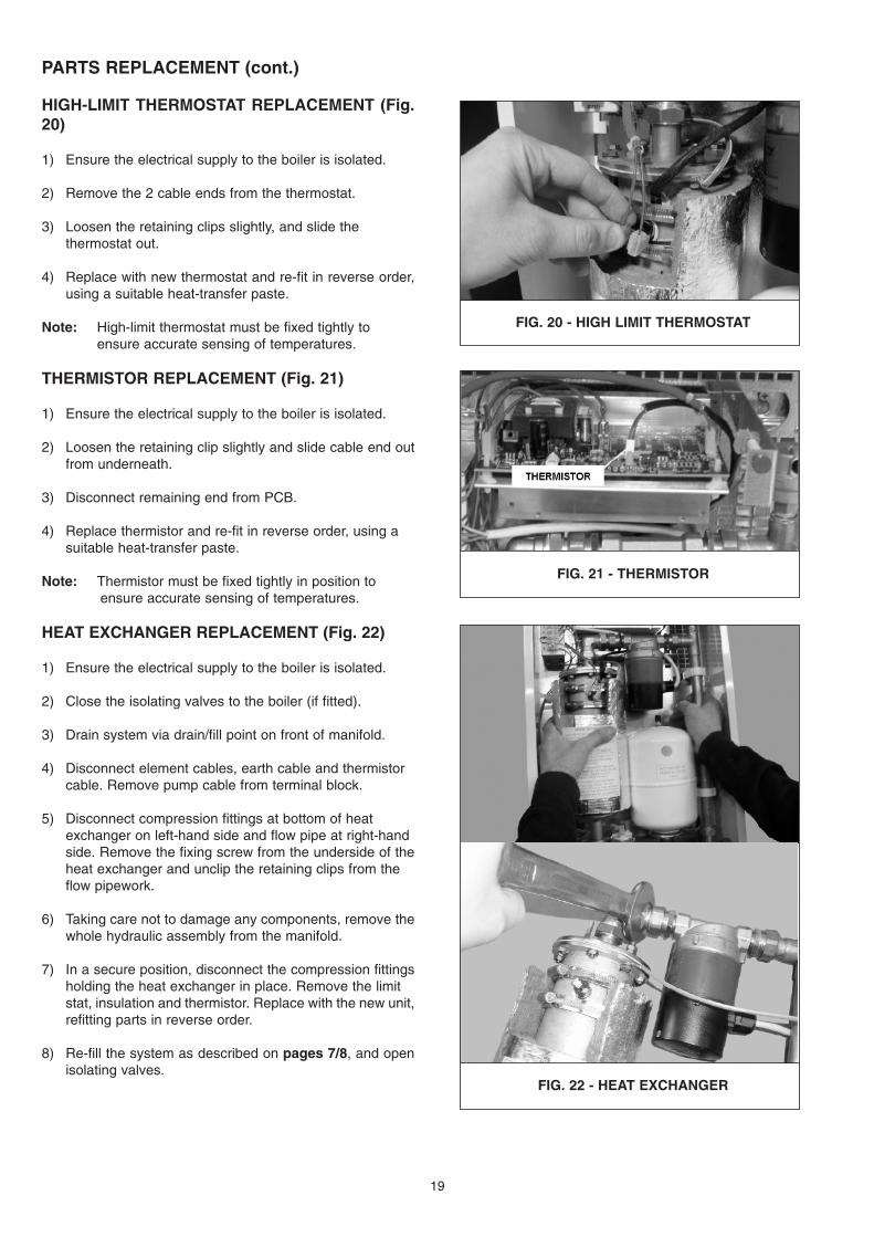
HIGH-LIMIT THERMOSTAT REPLACEMENT (Fig.20)
1) Ensure the electrical supply to the boiler is isolated.
2) Remove the 2 cable ends from the thermostat.
3) Loosen the retaining clips slightly, and slide the thermostat out.
4) Replace with new thermostat and re-fit in reverse order,using a suitable heat-transfer paste.
Note: High-limit thermostat must be fixed tightly to ensure accurate sensing of temperatures.
THERMISTOR REPLACEMENT (Fig. 21)
1) Ensure the electrical supply to the boiler is isolated.
2) Loosen the retaining clip slightly and slide cable end outfrom underneath.
3) Disconnect remaining end from PCB.
4) Replace thermistor and re-fit in reverse order, using a suitable heat-transfer paste.
Note: Thermistor must be fixed tightly in position to ensure accurate sensing of temperatures.
HEAT EXCHANGER REPLACEMENT (Fig. 22)
1) Ensure the electrical supply to the boiler is isolated.
2) Close the isolating valves to the boiler (if fitted).
3) Drain system via drain/fill point on front of manifold.
4) Disconnect element cables, earth cable and thermistor cable. Remove pump cable from terminal block.
5) Disconnect compression fittings at bottom of heat exchanger on left-hand side and flow pipe at right-hand side. Remove the fixing screw from the underside of theheat exchanger and unclip the retaining clips from the flow pipework.
6) Taking care not to damage any components, remove thewhole hydraulic assembly from the manifold.
7) In a secure position, disconnect the compression fittingsholding the heat exchanger in place. Remove the limit stat, insulation and thermistor. Replace with the new unit,refitting parts in reverse order.
8) Re-fill the system as described on pages 7/8, and openisolating valves.
19
FIG. 20 - HIGH LIMIT THERMOSTAT
FIG. 21 - THERMISTOR
FIG. 22 - HEAT EXCHANGER

PARTS REPLACEMENT (cont.)
PRESSURE SAFETY SWITCH REPLACEMENT(Fig. 23)
1) Ensure the electrical supply to the boiler is isolated.
2) Close the isolating valves to the boiler (if fitted).
3) Drain system via drain/fill point on front of manifold.
4) Disconnect the three wires from the top of the pressuresafety switch.
5) Unscrew pressure safety switch and replace with a newunit, re-fitting in reverse order.
6) Re-fill the system as described on pages 7/8, and openisolating valves.
Notes: Do not over-tighten connections to manifold as thiscould lead to thread damage.
Ensure a suitable thread sealant is used when screwingswitch into position.
EXPANSION VESSEL REPLACEMENT (Fig. 24)
1) Ensure the electrical supply to the boiler is isolated.
2) Close the isolating valves to the boiler (if fitted).
3) Drain system via drain/fill point on front of manifold.
4) Unscrew the expansion vessel and replace with a new unit, re-fitting in reverse order. Ensure a suitable thread sealant is used on all joints.
5) Re-fill the system as described on pages 7/8, and openisolating valves.
PUMP HEAD REPLACEMENT (Fig. 25)
1) Ensure the electrical supply to the boiler is isolated.
2) Close the isolating valves to the boiler (if fitted).
3) Drain system via drain/fill point on front of manifold.
4) Disconnect the pump power supply cables from the terminal block and unscrew pump head.
5) Clean any deposits from the inside of the body and replace the 'o' ring seal, if necessary.
6) Replace the pump head with a new unit, re-fitting in reverse order.
7) Re-fill the system as described on pages 7/8, and openisolating valves.
20
FIG. 23 - PRESSURE SWITCH
FIG. 24 - EXPANSION VESSEL
FIG. 25 - PUMP HEAD

21
Description No. Off 2kW Model 4kW ModelPart Code Part Code
Heat Exchanger/Element Assembly 1 222580 222629
PCB Controller 1 222558 222558
High-Limit Thermostat (100°C - for use with radiator heating systems) 1 221825 221825
High-Limit Thermostat (60°C - for use with underfloor heating systems) 1 222592 222592
Wiring Harness 1 222578 222630
High Limit Thermostat Wiring Harness 1 222576 222576
Thermistor & Cable 1 222548 222548
Pump 1 222557 222557
Expansion Vessel 1 222555 222555
Pressure Relief Valve 1 208069 208069
Pressure Safety Switch 1 222556 222556
Pressure Gauge 1 501808 501808
Automatic Air Vent 1 207296 207296
Door Casing Assembly (White) 1 222562 222562
Door Casing Assembly (Bronze) 1 222542 222542
SPARES LIST

Printed by WFO Press Ltd. (01709) 740078 April 2005 Item No. 222535 Issue No. 1 Rev. 0
TRIANCO LIMITEDThorncliffe, Chapeltown, Sheffield S35 2PH
Tel: Sheffield (0114) 257 2300Fax: (0114) 257 1419www.trianco.co.uk
© Trianco Limited, Copyright in this brochure and the drawings or illustrations contained in it is vested in Trianco Limited and neitherthe brochure or any part thereof may be reproduced without prior written consent.
Trianco Limited’s policy is one of continuous research and development. This may necessitate alterations to this specification.Instructions correct at time of going to print.
By appointment to H.M. Queen ElizabethThe Queen Mother
Manufacturers of Domestic Boilers
KM 59690