Azatel Communications Inc. 2-Port Multi-Protocol VOIP Gateway
126
Administrator Guide –Azatel VOIP Gateway Azatel Communications Inc. 2-Port Multi-Protocol VOIP Gateway Device Administrator Guide Version 1.5.6
Transcript of Azatel Communications Inc. 2-Port Multi-Protocol VOIP Gateway
Administrator Guide –Azatel VOIP Gateway
Azatel Communications Inc. 2-Port Multi-Protocol VOIP Gateway Device Administrator Guide
Version 1.5.6

Administrator Guide – AzaCall200 VOIP Multi-Protocol Gateway
Copyright Notice
All rights reserved, Azatel Communications Inc. - September 10th, 2004
The information in this document is subject to change without notice. The statements, configurations, technical data, and recommendations in this document are believed to be accurate and reliable, but are presented without express or implied warranty. Users must take full responsibility for their applications of any products specified in this document. The information in this document is proprietary to Azatel.
Trademark Acknowledgment
Internet Explorer™, Windows™, Windows 95™, and Windows NT™ are trademarks of Microsoft Corporation.
All other products or service names mentioned in this document may be trademarks of the companies with which they are associated.
Administrator Guide –AzaCall200 - VOIP Multi-Protocol Gateway
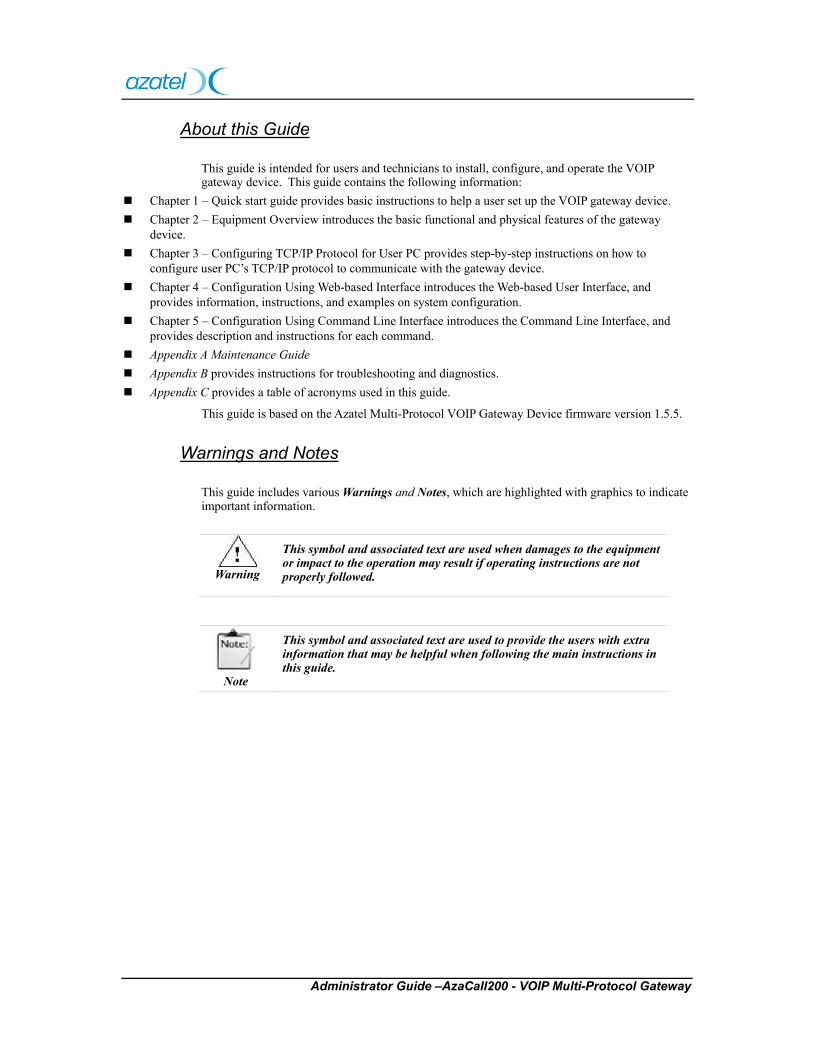
About this Guide
This guide is intended for users and technicians to install, configure, and operate the VOIP gateway device. This guide contains the following information:
Chapter 1 – Quick start guide provides basic instructions to help a user set up the VOIP gateway device. Chapter 2 – Equipment Overview introduces the basic functional and physical features of the gateway
device. Chapter 3 – Configuring TCP/IP Protocol for User PC provides step-by-step instructions on how to
configure user PC’s TCP/IP protocol to communicate with the gateway device. Chapter 4 – Configuration Using Web-based Interface introduces the Web-based User Interface, and
provides information, instructions, and examples on system configuration. Chapter 5 – Configuration Using Command Line Interface introduces the Command Line Interface, and
provides description and instructions for each command. Appendix A Maintenance Guide Appendix B provides instructions for troubleshooting and diagnostics. Appendix C provides a table of acronyms used in this guide.
This guide is based on the Azatel Multi-Protocol VOIP Gateway Device firmware version 1.5.5.
Warnings and Notes
This guide includes various Warnings and Notes, which are highlighted with graphics to indicate important information.
Warning
This symbol and associated text are used when damages to the equipment or impact to the operation may result if operating instructions are not properly followed.
Note
This symbol and associated text are used to provide the users with extra information that may be helpful when following the main instructions in this guide.
Administrator Guide – AzaCall200 VOIP Multi-Protocol Gateway
Safety
The following information relates to the safety of installation and maintenance personnel. Read all instructions before attempting to unpack or install or operate this equipment, and before connecting the power supply.
Please keep the following in mind as the user unpacks and installs this equipment:
1. Always follow basic safety precautions to reduce the risk of fire, electrical shock and injury to persons.
2. To prevent fire or shock hazard, do not expose the unit to rain, moisture or install this product near water.
3. Never spill liquid of any kind on or into this product.
4. Never push an object of any kind into this product through module openings or empty slots, as this may damage the AzaCall200.
5. Do not attach the power supply cabling to building surfaces. Do not allow anything to rest on the power cabling or allow it to be abused by persons walking on it.
6. To protect the equipment from overheating, do not block the slots and openings in the module housing that provide ventilation.
7. Use caution when installing or modifying telephone lines. Never install telephone wiring during an electrical storm.
Getting Technical Assistance
Should users encounter questions or problems with the gateway device and cannot resolve them by referring to the printed or on-line product documentation, Azatel and its authorized distributors are available to help them within the guidelines of our product support programs.
Contact your distributor as your primary source for technical support.
NOTE: Before placing the call to Azatel or its authorized distributors for further assistance, please have the following information ready:
• Gateway device supplier and order number. • Gateway device configuration. • Gateway device software release version number. • User questions or a description of the problem experienced.
If you purchased the AzaCall200 directly from Azatel, please be prepared to provide the following additional information: • Azatel Partner Service Number • Device Serial Number
Administrator Guide – AzaCall200 VOIP Multi-Protocol Gateway
1.1. Table of Contents
Azatel 2-Port Multi-Protocol VOIP Gateway Device Administrator Guide.............................................................................1 Copyright Notice ........................................................................................................................ ii Trademark Acknowledgment ...................................................................................................... ii About this Guide........................................................................................................................ iii Warnings and Notes................................................................................................................... iii Safety ......................................................................................................................................... iv Getting Technical Assistance..................................................................................................... iv Table of Contents................................................................................................... v List of Figures ...................................................................................................... ix
Chapter 2. Quick Start Guide .................................................................................1 2.1.Unpacking ....................................................................................................... 1 2.2.Hardware Installation ..................................................................................... 1 2.2.1.Hardware & Software Requirements................................................................................. 1 2.2.2.Getting Connected............................................................................................................. 2 2.3.Powering Up & Initialization .......................................................................... 6 2.3.1.LED Status......................................................................................................................... 6
Chapter 3. Equipment Overview............................................................................7 3.1.Introduction ..................................................................................................... 7 3.2.Features ........................................................................................................... 8 3.3.Front View (LEDs) .......................................................................................... 9 3.4.Rear View (Ports) .......................................................................................... 10
Chapter 4. Configuring TCP/IP Protocol for User PC ......................................... 11 4.1.Introduction ................................................................................................... 11 4.2.Windows 98/Me ........................................................................................... 11 4.3.Windows 2000/XP......................................................................................... 12 4.4.Windows NT ................................................................................................. 12
Administrator Guide – AzaCall200 VOIP Multi-Protocol Gateway
Chapter 5. Configuration Using Web-based Interface .........................................13 5.1.Configuring via Web Browser....................................................................... 14 5.2.Logging on to the Web-based Interface ........................................................ 15 5.3.System Functions .......................................................................................... 16 5.3.1.System Status .................................................................................................................. 16 5.3.2.DHCPC Status................................................................................................................. 17 5.3.3.PPPoE Status .................................................................................................................. 18 5.4.PPPoE Configuration .................................................................................... 19 5.4.1.PPPoE ............................................................................................................................ 19 5.5.WAN Configuration ...................................................................................... 20 5.5.1.WAN IP............................................................................................................................ 20 5.5.2.Provisioning .................................................................................................................... 22 5.5.3.Device Mode.................................................................................................................... 23 5.6.NTP Configuration ........................................................................................ 24 5.7.NAPT Configuration ..................................................................................... 25 5.7.1.LAN DHCP Configuration .............................................................................................. 25 5.7.2.Port Forwarding.............................................................................................................. 27 5.7.3.IP Filter ........................................................................................................................... 29 5.7.4.DMZ ................................................................................................................................ 30 5.8.QoS................................................................................................................ 31 5.8.1.QoS Configuration .......................................................................................................... 31 5.8.2.DSCP Configuration ....................................................................................................... 32 5.8.3.VLan Tag Configuration.................................................................................................. 33 5.9.MAC Cloning................................................................................................ 34 5.10.PSTN Configuration.................................................................................... 35 5.10.1.Switch Key ..................................................................................................................... 35 5.10.2.Digit Map ...................................................................................................................... 36 5.11.Provision Configuration .............................................................................. 37 5.12.Syslog Configuration................................................................................... 38 5.13.EMS Configuration ..................................................................................... 39 5.13.1.EMS ............................................................................................................................... 39 5.13.2.SNMP Community ......................................................................................................... 40 5.13.3.SNMP Trap Target ......................................................................................................... 41 5.14.VOIP Configuration .................................................................................... 42 5.14.1.Protocol ......................................................................................................................... 42 5.14.2.MGCP............................................................................................................................ 43 5.14.3.User ............................................................................................................................... 44 5.14.4.SIP ................................................................................................................................. 45 5.14.5.CODEC ......................................................................................................................... 46 5.14.6.RTP................................................................................................................................ 47 5.14.7.Tone ............................................................................................................................... 48 5.14.8.FAX ................................................................................................................................ 49 5.14.9.Simple Traversal of UDP through Network (STUN)..................................................... 50 5.14.10.Speed Dial ................................................................................................................... 51 5.14.11.VOIP Address Book ..................................................................................................... 52 5.14.12.Call Features ............................................................................................................... 53
Administrator Guide – AzaCall200 VOIP Multi-Protocol Gateway
5.14.13.VOIP Digit Map .......................................................................................................... 60 5.15.Password Configuration .............................................................................. 61 5.15.1.Supervisor Password..................................................................................................... 61 5.15.2.User Password .............................................................................................................. 62 5.16.Upgrade Configuration................................................................................ 63 5.16.1.Firmware ....................................................................................................................... 63 5.16.2.Configuration ................................................................................................................ 64 5.17.View............................................................................................................. 65 5.17.1.View Configuration........................................................................................................ 65 5.18.Save ............................................................................................................. 66 5.18.1.Save Configuration........................................................................................................ 66 5.18.2.Load Default Settings .................................................................................................... 66 5.19.Reboot ......................................................................................................... 67
Chapter 6. Configuration Using Command Line Interface ..................................68 6.1.Log into Command Line Interface ................................................................ 68 6.1.1.Console Port.................................................................................................................... 68 6.1.2.Remote Telnet .................................................................................................................. 70 6.2.Command Introduction ................................................................................. 70 6.2.1.“Tip” Command.............................................................................................................. 70 6.2.2.Commonly Used Commands ........................................................................................... 70 6.2.3.Administration Commands.............................................................................................. 71 6.2.4.Configuration Commands ............................................................................................... 72 6.2.5.Maintenance Commands ................................................................................................. 97 6.2.6.Diagnostic Commands .................................................................................................... 99
Appendix A. Maintenance Guide........................................................................... 105
Appendix B. LED Status...................................................................................................... 105
Appendix C. Recovery Procedure...................................................................................... 106
Appendix D. Software Description .................................................................................................. 106
Appendix E. Recovery Procedure .................................................................................................... 106
Appendix F. Syslog message list ....................................................................................... 111
Administrator Guide – AzaCall200 VOIP Multi-Protocol Gateway
Appendix G. SNMP Trap message list.............................................................................. 111
Appendix H. Troubleshooting and Diagnostics ..................................................... 112
Appendix I. Acronyms ........................................................................................ 113
Administrator Guide – AzaCall200 VOIP Multi-Protocol Gateway
1.2. List of Figures
Figure 1 Connectivity diagram for cable modem with NAT device.....3 Figure 2 Connectivity diagram for ADSL modem with NAT device ..4 Figure 3 Connectivity diagram for Metro-Ethernet connection ...........5 Figure 4 Network Environment Using the Multi-Protocol Gateway Device in Gateway Mode .....................................................................7 Figure 5 Network Environment Using the Multi-Protocol Gateway Device in Bridge Mode ........................................................................8 Figure 6 Gateway Device Front Panel..................................................9 Figure 7 Gateway Device Rear Panel.................................................10 Figure 8 Web Browser Address Field.................................................14 Figure 9 Login Window......................................................................15 Figure 10 System Status Window.......................................................16 Figure 11 DHCPC Status Window .....................................................17 Figure 12 PPPoE Status Window .......................................................18 Figure 13 PPPOE Configuration Window..........................................19 Figure 14 WAN Configuration Window.............................................21 Figure 15 WAN Provision Configuration Window ............................22 Figure 16 Device Mode Configuration Window ................................23 Figure 17 NTP Configuration Window ..............................................24 Figure 18 DHCP Configuration Window ...........................................26 Figure 19 Port Forwarding Rule/Rule Table Window........................27 Figure 20 IP Filter Configuration Window.........................................29 Figure 21 DMZ Configuration Window.............................................30 Figure 22 Qos Configuration Window ...............................................31 Figure 23 DHCP Configuration Window ...........................................32 Figure 24 VLan Tag Configuration Window......................................33 Figure 25 MAC Cloning Window ......................................................34 Figure 26 PSTN Switch Key Window................................................35
Administrator Guide – AzaCall200 VOIP Multi-Protocol Gateway
Figure 27 PSTN Digitmap Window ...................................................36 Figure 28 Provision Configuration Window ......................................37 Figure 29 Syslog Configuration Window...........................................38 Figure 30 EMS Configuration Window..............................................39 Figure 31 SNMP Community Configuration Window.......................40 Figure 32 SNMP Trap Configuration Window...................................41 Figure 33 VOIP Protocol Selection Window......................................42 Figure 34 MGCP Configuration Window...........................................43 Figure 35 VOIP User Configuration Window ....................................44 Figure 36 VOIP SIP Configuration Window ......................................45 Figure 37 VOIP Codec Configuration Window .................................46 Figure 38 VOIP RTP Configuration Window.....................................47 Figure 39 VOIP Tone Configuration Window....................................48 Figure 40 VOIP Fax Configuration Window......................................49 Figure 41 VOIP STUN Configuration Window .................................50 Figure 42 VOIP Speed Dial Configuration Window ..........................51 Figure 43 VOIP Address Book Window.............................................52 Figure 44 Call Hold Diagram.............................................................53 Figure 45 Call Waiting Diagram.........................................................54 Figure 46 Call Forwarding Always Diagram .....................................55 Figure 47 Call Forwarding Busy Diagram .........................................55 Figure 48 Call Forwarding No Answer Diagram ...............................56 Figure 49 Blind Transfer ....................................................................57 Figure 50 3-Way Call Conference Diagram .......................................58 Figure 51 VOIP Call Feature Configuration Window ........................59 Figure 52 VOIP Call Digit Map Configuration Window....................60 Figure 53 Supervisor Password Window............................................61 Figure 54 User Password Window .....................................................62 Figure 55 Firmware Upgrade Window...............................................63
Administrator Guide – AzaCall200 VOIP Multi-Protocol Gateway
Figure 56 Configuration Upgrade Window........................................64 Figure 57 View Configuration Window .............................................65 Figure 58 Window Showing Configuration Save to Flash .................66 Figure 59 Load Default Settings Window ..........................................66 Figure 60 Reboot Window..................................................................67 Figure 61 Console Port Cable Diagram..............................................69 Figure 62 Hyper Terminal Parameters................................................69 Figure 63 Command Line Interface Screen........................................70 Figure 64 Recovery Procedures........................................................ 107 Figure 65 Complete Maintenance Mode (via console port) ............. 109 Figure 66 Simple Maintenance Mode (via telnet) ............................ 109

1
Administrator Guide – AzaCall200 VOIP Multi-Protocol Gateway
Chapter 2. Quick Start Guide
This chapter provides the basic instructions and information that will help a user set up the VOIP Gateway device in the user’s network environment. By following the steps listed here the user will be able to connect power and data cables to the device, then perform basic configuration to enable normal operation by the device. More detailed device configuration information is presented in a later chapter titled “Configuration Using Web-based Interface”.
2.1. Unpacking Carefully unpack the user package and make sure that the following items are available.
1. One VOIP Residential Gateway
2. One RJ-11 telephone line for the first telephone
3. One RJ-11 telephone line for PSTN back-up use (optional)
4. One RJ-45 Ethernet cable
5. One power adapter
If the user finds anything missing or damaged, promptly contact the dealer from whom the user purchased the product for help.
2.2. Hardware Installation
2.2.1. Hardware & Software Requirements
The items listed below are the minimum hardware and software requirements needed before commencing with the installation procedure.
1. One RJ-45 broadband Internet connection via cable modem, ADSL modem or other broadband access devices
2. One PC with 10Mbps, 100Mbps, or 10/100 Mbps Ethernet card installed
3. TCP/IP protocol for each PC
4. Microsoft Internet Explorer 4.0 or later (5.0 is strongly recommended for web configuration)
5. One standard touch-tone telephone
6. Subscription to VOIP service from a VOIP service provider
2
Administrator Guide – AzaCall200 VOIP Multi-Protocol Gateway
2.2.2. Getting Connected
1. LINE Port:
Plug one end of the RJ-11 telephone line into the LINE port and plug the other end into the phone socket in the wall using an RJ-11 telephone line.
2. PHONE Port:
Plug one end of the RJ-11 telephone line into the PHONE port and plug the other end into the phone socket of a telephone set.
3. PWR Port:
Plug one end of the power adapter into the PWR port and plug the other end into an electric outlet in the wall.
Warning
Use only the enclosed power adapter accompanying the gateway device. Faulty or improper voltage input may cause permanent damage to the power supply and the gateway device thereby voiding the warranty.
4. ENET Port:
Plug one end of the RJ-45 Ethernet cable into the ENET port and plug the other end into the Ethernet socket of the Network Interface Card (NIC) in the user’s PC.
3
Administrator Guide – AzaCall200 VOIP Multi-Protocol Gateway
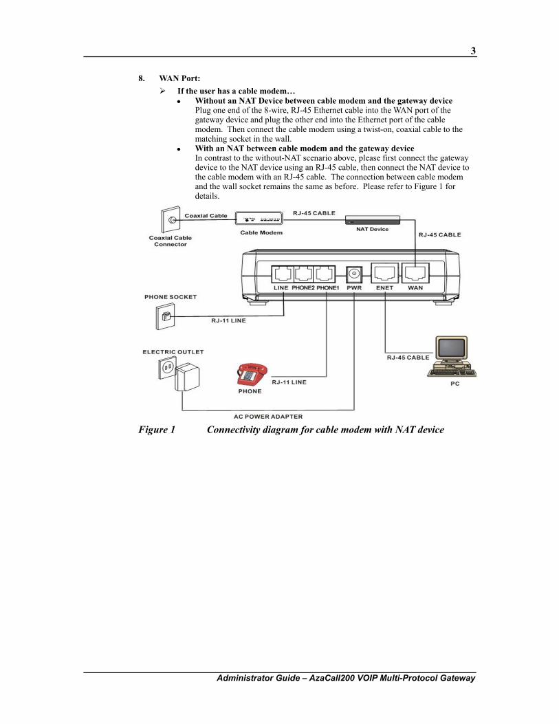
8. WAN Port: If the user has a cable modem…
Without an NAT Device between cable modem and the gateway device Plug one end of the 8-wire, RJ-45 Ethernet cable into the WAN port of the gateway device and plug the other end into the Ethernet port of the cable modem. Then connect the cable modem using a twist-on, coaxial cable to the matching socket in the wall.
With an NAT between cable modem and the gateway device In contrast to the without-NAT scenario above, please first connect the gateway device to the NAT device using an RJ-45 cable, then connect the NAT device to the cable modem with an RJ-45 cable. The connection between cable modem and the wall socket remains the same as before. Please refer to Figure 1 for details.
Figure 1 Connectivity diagram for cable modem with NAT device
4
Administrator Guide – AzaCall200 VOIP Multi-Protocol Gateway
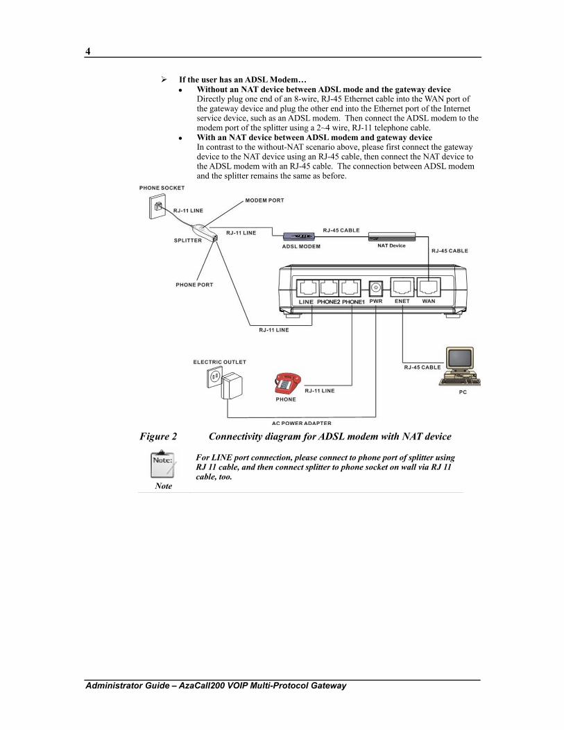
If the user has an ADSL Modem… Without an NAT device between ADSL mode and the gateway device
Directly plug one end of an 8-wire, RJ-45 Ethernet cable into the WAN port of the gateway device and plug the other end into the Ethernet port of the Internet service device, such as an ADSL modem. Then connect the ADSL modem to the modem port of the splitter using a 2~4 wire, RJ-11 telephone cable.
With an NAT device between ADSL modem and gateway device In contrast to the without-NAT scenario above, please first connect the gateway device to the NAT device using an RJ-45 cable, then connect the NAT device to the ADSL modem with an RJ-45 cable. The connection between ADSL modem and the splitter remains the same as before.
Figure 2 Connectivity diagram for ADSL modem with NAT device
Note
For LINE port connection, please connect to phone port of splitter using RJ 11 cable, and then connect splitter to phone socket on wall via RJ 11 cable, too.
5
Administrator Guide – AzaCall200 VOIP Multi-Protocol Gateway
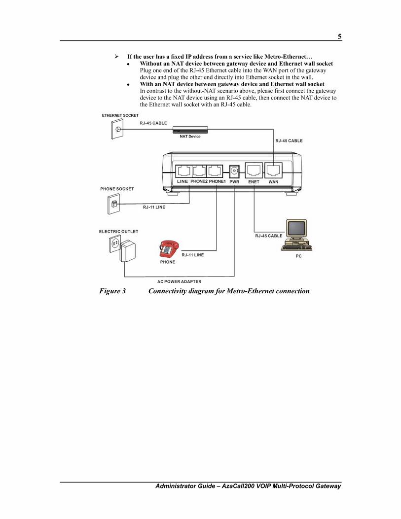
If the user has a fixed IP address from a service like Metro-Ethernet… Without an NAT device between gateway device and Ethernet wall socket
Plug one end of the RJ-45 Ethernet cable into the WAN port of the gateway device and plug the other end directly into Ethernet socket in the wall.
With an NAT device between gateway device and Ethernet wall socket In contrast to the without-NAT scenario above, please first connect the gateway device to the NAT device using an RJ-45 cable, then connect the NAT device to the Ethernet wall socket with an RJ-45 cable.
Figure 3 Connectivity diagram for Metro-Ethernet connection
6
Administrator Guide – AzaCall200 VOIP Multi-Protocol Gateway
2.3. Powering Up & Initialization
2.3.1. LED Status
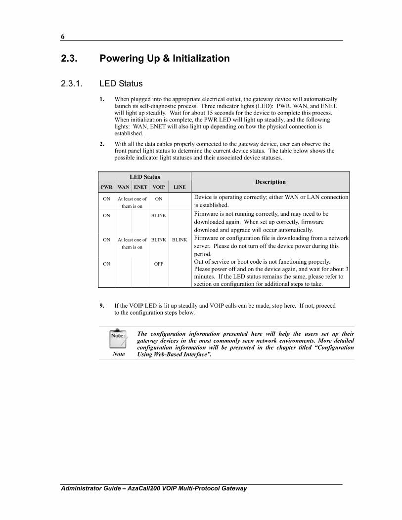
1. When plugged into the appropriate electrical outlet, the gateway device will automatically launch its self-diagnostic process. Three indicator lights (LED): PWR, WAN, and ENET, will light up steadily. Wait for about 15 seconds for the device to complete this process. When initialization is complete, the PWR LED will light up steadily, and the following lights: WAN, ENET will also light up depending on how the physical connection is established.
2. With all the data cables properly connected to the gateway device, user can observe the front panel light status to determine the current device status. The table below shows the possible indicator light statuses and their associated device statuses.
LED Status
PWR WAN ENET VOIP LINE Description
ON At least one of them is on
ON Device is operating correctly; either WAN or LAN connection is established.
ON BLINK Firmware is not running correctly, and may need to be downloaded again. When set up correctly, firmware download and upgrade will occur automatically.
ON At least one of them is on
BLINK BLINK
Firmware or configuration file is downloading from a network server. Please do not turn off the device power during this period.
ON OFF Out of service or boot code is not functioning properly. Please power off and on the device again, and wait for about 3 minutes. If the LED status remains the same, please refer to section on configuration for additional steps to take.
9. If the VOIP LED is lit up steadily and VOIP calls can be made, stop here. If not, proceed to the configuration steps below.
Note
The configuration information presented here will help the users set up their gateway devices in the most commonly seen network environments. More detailed configuration information will be presented in the chapter titled “Configuration Using Web-Based Interface”.
7
Administrator Guide – AzaCall200 VOIP Multi-Protocol Gateway
Chapter 3. Equipment Overview
Our equipment device is a VOIP Gateway that delivers voice information over the Internet instead of the traditional telephone network. This benefits small offices and work-at-home users having high-speed Internet access by allowing them to use many service providers that offer toll-free or low-cost voice services. In addition, the VOIP Gateway features a PSTN back-up line, allowing users to still use the PSTN phone line should the VOIP service become unavailable, such as when there is a power outage. Equipment configuration via Graphical User Interface (GUI) is also available, allowing users to easily configure the equipment and software settings via a web browser like the Internet Explorer. Firmware upgrade via TFTP is also supported, allowing users to easily add newer and more powerful features to their gateway devices.
3.1. Introduction The AzaCall200 gateway device is an external stand-alone device, which can provide a cost-effective long-distance voice communication solution using the Internet. The gateway device can establish a voice channel by adopting Voice Over Internet Protocol (VOIP) signaling schemes after registering itself with a designated proxy server. The gateway device can be connected directly to phones, fax machines, PBXs, and the Internet without any additional accessories or set ups. When the Ethernet port of the gateway device is connected to another device with a WAN interface (e.g. ADSL modem), the gateway device can provide toll quality voice communication in terms of voice quality and reliability for the users.
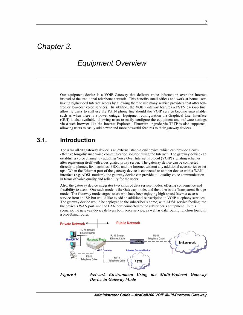
Also, the gateway device integrates two kinds of data service modes, offering convenience and flexibility to users. One such mode is the Gateway mode, and the other is the Transparent Bridge mode. The Gateway mode targets users who have been enjoying high-speed Internet access service from an ISP, but would like to add an additional subscription to VOIP telephony services. The gateway device would be deployed to the subscriber’s home, with ADSL service feeding into the device’s WAN port, and the LAN port connected to the subscriber’s equipment. In this scenario, the gateway device delivers both voice service, as well as data routing function found in a broadband router.
Figure 4 Network Environment Using the Multi-Protocol Gateway Device in Gateway Mode
8
Administrator Guide – AzaCall200 VOIP Multi-Protocol Gateway
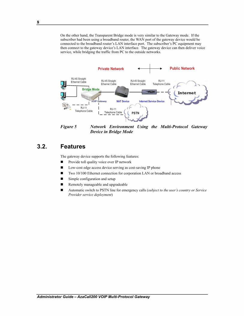
On the other hand, the Transparent Bridge mode is very similar to the Gateway mode. If the subscriber had been using a broadband router, the WAN port of the gateway device would be connected to the broadband router’s LAN interface port. The subscriber’s PC equipment may then connect to the gateway device’s LAN interface. The gateway device can then deliver voice service, while bridging the traffic from PC to the outside networks.
Figure 5 Network Environment Using the Multi-Protocol Gateway Device in Bridge Mode
3.2. Features The gateway device supports the following features:
Provide toll quality voice over IP network Low-cost edge access device serving as cost-saving IP phone Two 10/100 Ethernet connection for corporation LAN or broadband access Simple configuration and setup Remotely manageable and upgradeable Automatic switch to PSTN line for emergency calls (subject to the user’s country or Service
Provider service deployment)
9
Administrator Guide – AzaCall200 VOIP Multi-Protocol Gateway
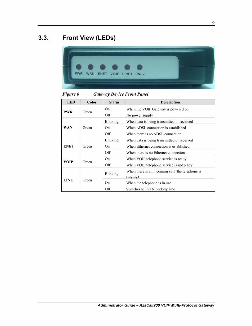
3.3. Front View (LEDs)
Figure 6 Gateway Device Front Panel
LED Color Status Description
On When the VOIP Gateway is powered on PWR Green
Off No power supply Blinking When data is being transmitted or received On When ADSL connection is established WAN Green Off When there is no ADSL connection Blinking When data is being transmitted or received On When Ethernet connection is established ENET Green Off When there is no Ethernet connection On When VOIP telephone service is ready
VOIP Green Off When VOIP telephone service is not ready
Blinking When there is an incoming call (the telephone is ringing)
On When the telephone is in useLINE Green
Off Switches to PSTN back-up line
10
Administrator Guide – AzaCall200 VOIP Multi-Protocol Gateway
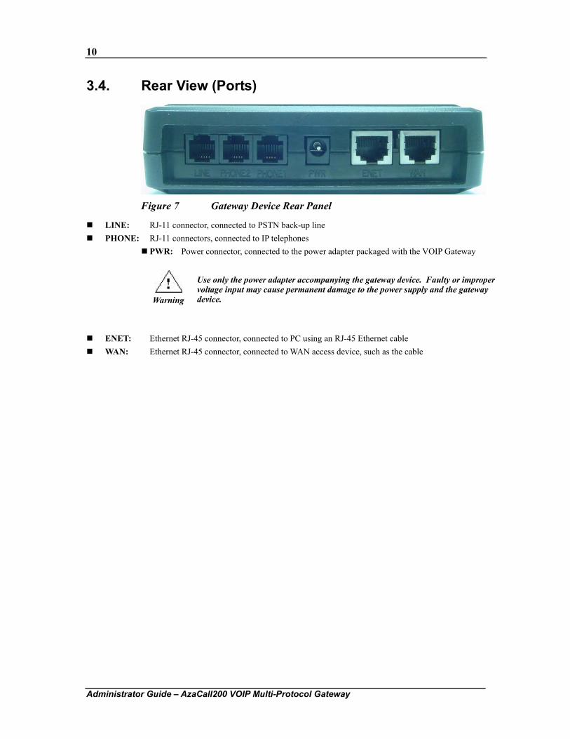
3.4. Rear View (Ports)
Figure 7 Gateway Device Rear Panel
LINE: RJ-11 connector, connected to PSTN back-up line PHONE: RJ-11 connectors, connected to IP telephones
PWR: Power connector, connected to the power adapter packaged with the VOIP Gateway
Warning
Use only the power adapter accompanying the gateway device. Faulty or improper voltage input may cause permanent damage to the power supply and the gateway device.
ENET: Ethernet RJ-45 connector, connected to PC using an RJ-45 Ethernet cable WAN: Ethernet RJ-45 connector, connected to WAN access device, such as the cable
11
Administrator Guide – AzaCall200 VOIP Multi-Protocol Gateway
Chapter 4. Configuring TCP/IP Protocol for User PC
This chapter explains the procedures used in configuring the TCP/IP protocols on the user’s PCs running different operating systems. It is mandatory that users follow the steps exactly as listed below so that the gateway device will operate normally.
4.1. Introduction To configure and communicate with this device, each PC on the user’s LAN must install TCP/IP protocol. If the user enables static IP addressing, make sure the user PC resides in the same subnet as the device’s LAN port. In Bridge Mode with the WAN side of the gateway device in DHCP mode, the default IP Address is 172.25.25.1 and default subnet mask: 255.255.255.0 once the PC connects to the WAN side. In Gateway Mode, the IP Address of the LAN port is 172.25.25.1 and the subnet mask is 255.255.255.0. The TA device is set to bridge mode by default.
4.2. Windows 98/Me 1. From the Start menu, click Settings, and then click Control Panel.
2. Double-click Network.
3. On the Configuration tab, check if TCP/IP protocol is installed on the components list.
4. If yes, go to step 8. If no, then click Add.
5. Highlight Protocol and click Add.
6. Select Microsoft from the Manufacturers list and select TCP/IP from the Network Protocols list.
7. Click OK. User will see TCP/IP displayed on the network components list.
8. Highlight TCP/IP and click Properties.
9. Select the IP Address tab and check Specify an IP address.
10. Set IP address as 172.25.25.1, Subnet mask as 255.255.255.0 and press OK.
12
Administrator Guide – AzaCall200 VOIP Multi-Protocol Gateway
4.3. Windows 2000/XP 1. From the Windows 2000 Start menu, click Settings, and then click Network and Dial-up
Connections. From Windows XP Start menu, click Control Panel, then click Internet Connection.
2. Double-click the Local Area Connection.
3. Click Properties.
4. Click Internet Protocol (TCP/IP) and then click Properties.
5. Check Use the following IP address.
6. Set IP address as 172.25.25.1, Subnet mask as 255.255.255.0 and press OK.
4.4. Windows NT 1. From the Start menu, click Settings, and then click Control Panel.
2. Double-click Network.
3. On the Protocol tab, check if TCP/IP protocol is installed on the components list.
4. If yes, go to Step 7. If no, then click Add.
5. Highlight TCP/IP Protocol and click OK.
6. Select TCP/IP Protocol and click Properties.
7. When Information Message appears, click OK.
8. On the IP Address tab, check Specify an IP address.
9. Set IP address as 172.25.25.1, Subnet mask as 255.255.255.0 and press OK.
10. When asked to restart user computer, click Yes.
13
Administrator Guide – AzaCall200 VOIP Multi-Protocol Gateway
Chapter 5. Configuration Using Web-based Interface
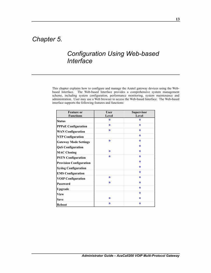
This chapter explains how to configure and manage the Azatel gateway devices using the Web-based Interface. The Web-based Interface provides a comprehensive system management scheme, including system configuration, performance monitoring, system maintenance and administration. User may use a Web browser to access the Web-based Interface. The Web-based interface supports the following features and functions:
Feature or Functions
User Level
Supervisor Level
Status * * PPPoE Configuration * * WAN Configuration * * NTP Configuration * Gateway Mode Settings * * QoS Configuration * MAC Cloning * * PSTN Configuration * * Provision Configuration * Syslog Configuration * EMS Configuration * VOIP Configuration * * Password * * Upgrade * View * Save * * Reboot * *
14
Administrator Guide – AzaCall200 VOIP Multi-Protocol Gateway
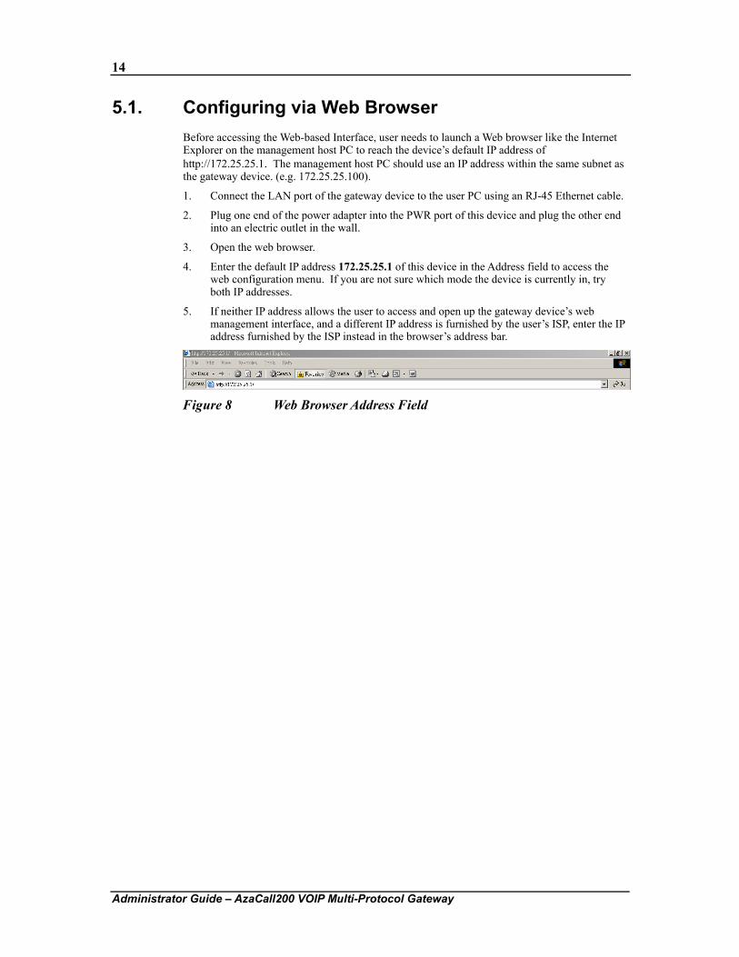
5.1. Configuring via Web Browser Before accessing the Web-based Interface, user needs to launch a Web browser like the Internet Explorer on the management host PC to reach the device’s default IP address of http://172.25.25.1. The management host PC should use an IP address within the same subnet as the gateway device. (e.g. 172.25.25.100).
1. Connect the LAN port of the gateway device to the user PC using an RJ-45 Ethernet cable.
2. Plug one end of the power adapter into the PWR port of this device and plug the other end into an electric outlet in the wall.
3. Open the web browser.
4. Enter the default IP address 172.25.25.1 of this device in the Address field to access the web configuration menu. If you are not sure which mode the device is currently in, try both IP addresses.
5. If neither IP address allows the user to access and open up the gateway device’s web management interface, and a different IP address is furnished by the user’s ISP, enter the IP address furnished by the ISP instead in the browser’s address bar.
Figure 8 Web Browser Address Field
15
Administrator Guide – AzaCall200 VOIP Multi-Protocol Gateway
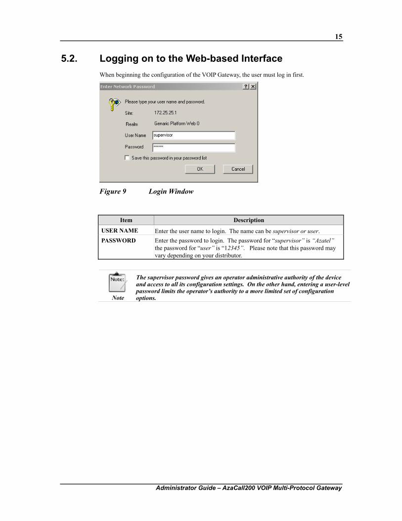
5.2. Logging on to the Web-based Interface When beginning the configuration of the VOIP Gateway, the user must log in first.
Figure 9 Login Window
Item Description
USER NAME Enter the user name to login. The name can be supervisor or user. PASSWORD Enter the password to login. The password for “supervisor” is “Azatel”
the password for “user” is “12345”. Please note that this password may vary depending on your distributor.
Note
The supervisor password gives an operator administrative authority of the device and access to all its configuration settings. On the other hand, entering a user-level password limits the operator’s authority to a more limited set of configuration options.
16
Administrator Guide – AzaCall200 VOIP Multi-Protocol Gateway
5.3. System Functions
5.3.1. System Status
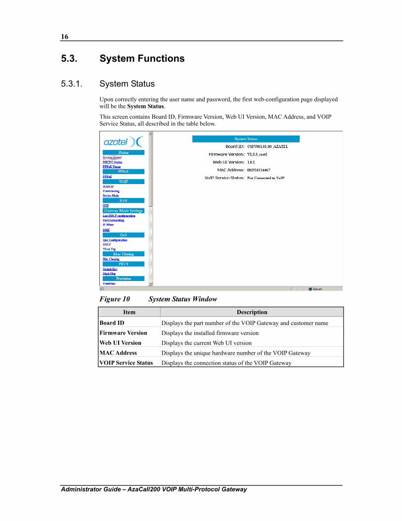
Upon correctly entering the user name and password, the first web-configuration page displayed will be the System Status.
This screen contains Board ID, Firmware Version, Web UI Version, MAC Address, and VOIP Service Status, all described in the table below.
Figure 10 System Status Window
Item Description
Board ID Displays the part number of the VOIP Gateway and customer name Firmware Version Displays the installed firmware version Web UI Version Displays the current Web UI version MAC Address Displays the unique hardware number of the VOIP Gateway VOIP Service Status Displays the connection status of the VOIP Gateway
17
Administrator Guide – AzaCall200 VOIP Multi-Protocol Gateway
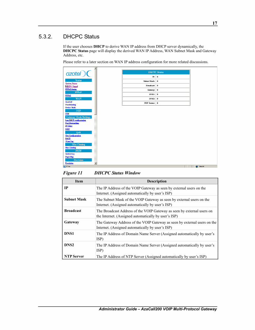
5.3.2. DHCPC Status
If the user chooses DHCP to derive WAN IP address from DHCP server dynamically, the DHCPC Status page will display the derived WAN IP Address, WAN Subnet Mask and Gateway Address, etc.
Please refer to a later section on WAN IP address configuration for more related discussions.
Figure 11 DHCPC Status Window
Item Description
IP The IP Address of the VOIP Gateway as seen by external users on the Internet. (Assigned automatically by user’s ISP)
Subnet Mask The Subnet Mask of the VOIP Gateway as seen by external users on the Internet. (Assigned automatically by user’s ISP)
Broadcast The Broadcast Address of the VOIP Gateway as seen by external users on the Internet. (Assigned automatically by user’s ISP)
Gateway The Gateway Address of the VOIP Gateway as seen by external users on the Internet. (Assigned automatically by user’s ISP)
DNS1 The IP Address of Domain Name Server (Assigned automatically by user’s ISP)
DNS2 The IP Address of Domain Name Server (Assigned automatically by user’s ISP)
NTP Server The IP Address of NTP Server (Assigned automatically by user’s ISP)
18
Administrator Guide – AzaCall200 VOIP Multi-Protocol Gateway
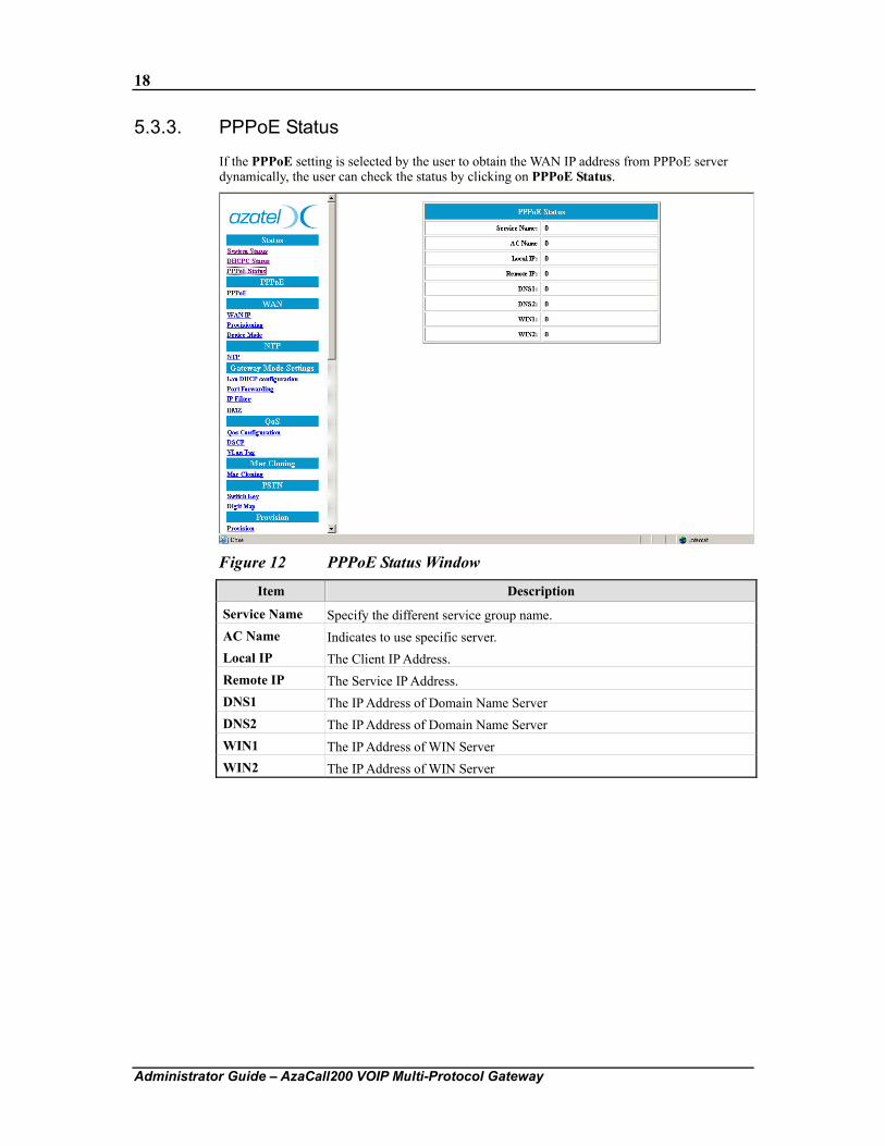
5.3.3. PPPoE Status
If the PPPoE setting is selected by the user to obtain the WAN IP address from PPPoE server dynamically, the user can check the status by clicking on PPPoE Status.
Figure 12 PPPoE Status Window
Item Description
Service Name Specify the different service group name. AC Name Indicates to use specific server. Local IP The Client IP Address. Remote IP The Service IP Address. DNS1 The IP Address of Domain Name Server DNS2 The IP Address of Domain Name Server WIN1 The IP Address of WIN Server WIN2 The IP Address of WIN Server
19
Administrator Guide – AzaCall200 VOIP Multi-Protocol Gateway
5.4. PPPoE Configuration
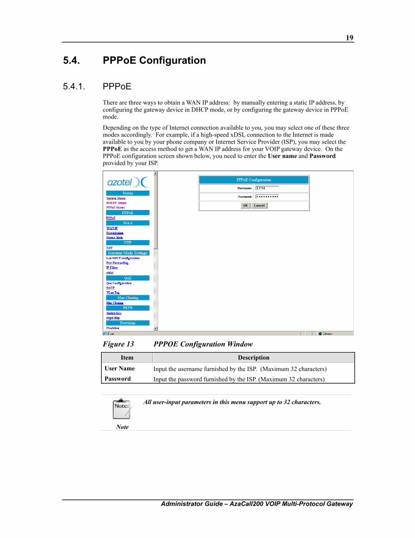
5.4.1. PPPoE
There are three ways to obtain a WAN IP address: by manually entering a static IP address, by configuring the gateway device in DHCP mode, or by configuring the gateway device in PPPoE mode.
Depending on the type of Internet connection available to you, you may select one of these three modes accordingly. For example, if a high-speed xDSL connection to the Internet is made available to you by your phone company or Internet Service Provider (ISP), you may select the PPPoE as the access method to get a WAN IP address for your VOIP gateway device. On the PPPoE configuration screen shown below, you need to enter the User name and Password provided by your ISP.
Figure 13 PPPOE Configuration Window
Item Description
User Name Input the username furnished by the ISP. (Maximum 32 characters) Password Input the password furnished by the ISP. (Maximum 32 characters)
Note
All user-input parameters in this menu support up to 32 characters.
20
Administrator Guide – AzaCall200 VOIP Multi-Protocol Gateway
5.5. WAN Configuration
5.5.1. WAN IP
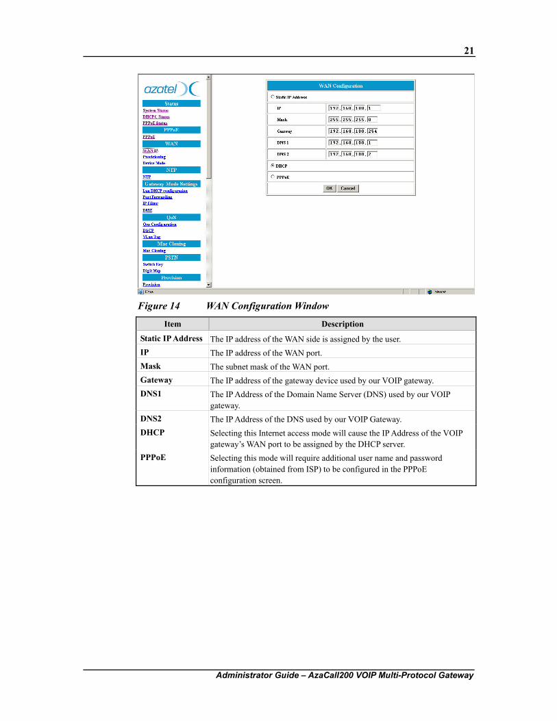
User can decide on the method of obtaining the WAN IP address for the VOIP gateway device by selecting one of the three choices listed in the WAN IP Configuration window. After the new configuration is saved and the device rebooted, the setting changes made by the user will take effect.
As shown in the figure below, there are three methods for the gateway device to obtain an IP address. These are the Static IP address, DHCP (default settings), and PPPoE.
If the user selects the static IP address item, please be sure to configure all the IP address related parameters on screen.
Note
The static IP address, address mask, and other related information may be obtained from the Internet Service Provider.
If the user selects DHCP, there are no other parameters to fill in the values in this configuration window. When the gateway device has been dynamically configured by the Service Provider’s DHCP server, the user may also observe the device’s current IP address and other related information by entering the DHCPC Status menu (refer to an earlier section in this chapter on DHCPC Status).
If the user selects PPPoE, please also go to the PPPoE configuration menu (refer to an earlier section in this chapter on PPPoE Configuration) to configure the username and password for authentication by the ISP. After rebooting the device and gaining access to the Internet or the service network, the user may observe the device’s current IP address and other related information by entering the PPPoE Status menu (refer to an earlier section on PPPoE Status).
Note
The PPPoE configuration information may be obtained from the Internet Service Provider.
All of the new or changed settings will take effect after the user reboots the gateway device, so please remember to click on the “OK” button in this configuration menu first, and then “Save Configuration” and “Reboot” so that the new settings may take effect.
The figure below shows that “DHCP” mode is selected as the Internet access protocol for our VOIP gateway device.
21
Administrator Guide – AzaCall200 VOIP Multi-Protocol Gateway
Figure 14 WAN Configuration Window
Item Description
Static IP Address The IP address of the WAN side is assigned by the user. IP The IP address of the WAN port. Mask The subnet mask of the WAN port. Gateway The IP address of the gateway device used by our VOIP gateway. DNS1 The IP Address of the Domain Name Server (DNS) used by our VOIP
gateway. DNS2 The IP Address of the DNS used by our VOIP Gateway. DHCP Selecting this Internet access mode will cause the IP Address of the VOIP
gateway’s WAN port to be assigned by the DHCP server. PPPoE Selecting this mode will require additional user name and password
information (obtained from ISP) to be configured in the PPPoE configuration screen.
22
Administrator Guide – AzaCall200 VOIP Multi-Protocol Gateway
5.5.2. Provisioning
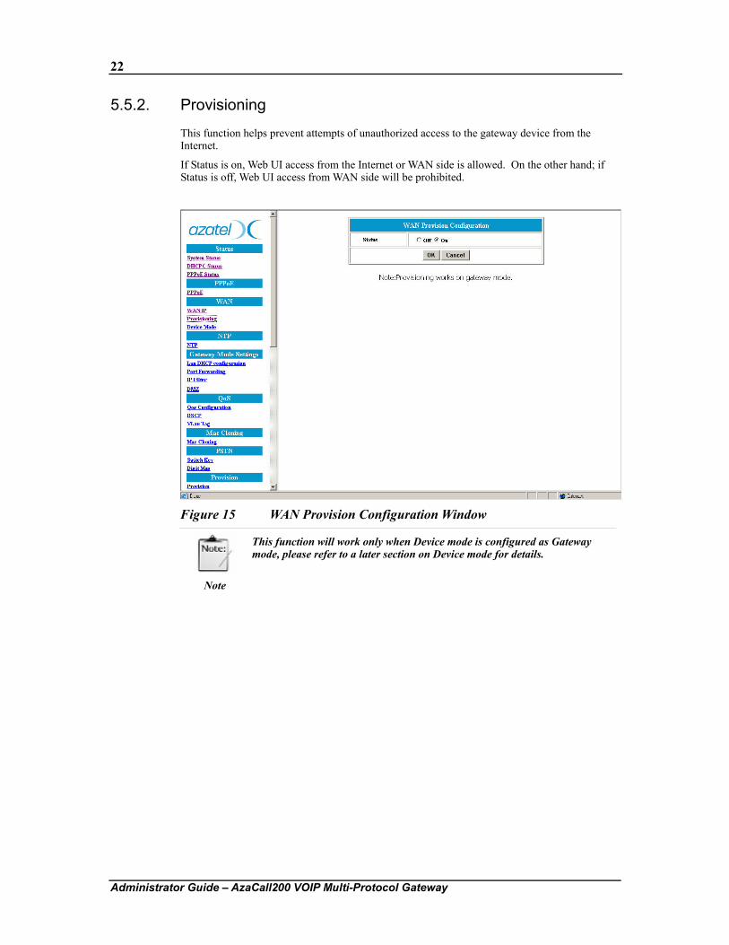
This function helps prevent attempts of unauthorized access to the gateway device from the Internet.
If Status is on, Web UI access from the Internet or WAN side is allowed. On the other hand; if Status is off, Web UI access from WAN side will be prohibited.
Figure 15 WAN Provision Configuration Window
Note
This function will work only when Device mode is configured as Gateway mode, please refer to a later section on Device mode for details.
23
Administrator Guide – AzaCall200 VOIP Multi-Protocol Gateway
5.5.3. Device Mode
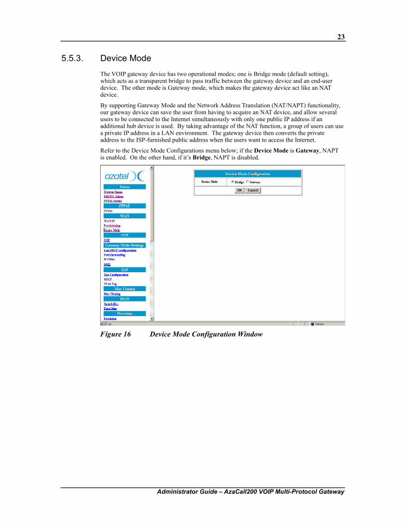
The VOIP gateway device has two operational modes; one is Bridge mode (default setting), which acts as a transparent bridge to pass traffic between the gateway device and an end-user device. The other mode is Gateway mode, which makes the gateway device act like an NAT device.
By supporting Gateway Mode and the Network Address Translation (NAT/NAPT) functionality, our gateway device can save the user from having to acquire an NAT device, and allow several users to be connected to the Internet simultaneously with only one public IP address if an additional hub device is used. By taking advantage of the NAT function, a group of users can use a private IP address in a LAN environment. The gateway device then converts the private address to the ISP-furnished public address when the users want to access the Internet.
Refer to the Device Mode Configurations menu below; if the Device Mode is Gateway, NAPT is enabled. On the other hand, if it’s Bridge, NAPT is disabled.
Figure 16 Device Mode Configuration Window
24
Administrator Guide – AzaCall200 VOIP Multi-Protocol Gateway
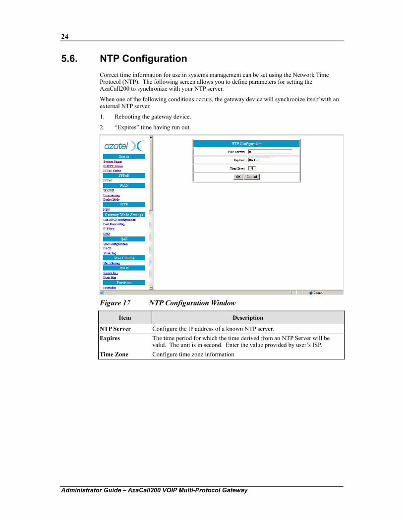
5.6. NTP Configuration Correct time information for use in systems management can be set using the Network Time Protocol (NTP). The following screen allows you to define parameters for setting the AzaCall200 to synchronize with your NTP server.
When one of the following conditions occurs, the gateway device will synchronize itself with an external NTP server.
1. Rebooting the gateway device.
2. “Expires” time having run out.
Figure 17 NTP Configuration Window
Item Description
NTP Server Configure the IP address of a known NTP server. Expires The time period for which the time derived from an NTP Server will be
valid. The unit is in second. Enter the value provided by user’s ISP. Time Zone Configure time zone information
25
Administrator Guide – AzaCall200 VOIP Multi-Protocol Gateway
5.7. NAPT Configuration When the gateway device operates in the Gateway mode, it supports the NAT (NAPT) feature, which means that WAN and LAN interfaces are located in different network segments and data traffic needs to be routed between the two interfaces. This feature helps to save on the consumption of public IP addresses but brings with it some restrictions as well. For example, certain types of traffic originating from WAN cannot pass through the gateway device because of IP mapping or security reasons. The following sections will help users overcome such IP address restrictions and internal routing to NAT’d endpoints.
Note
The functions described in this section will work only when Device mode is configured as Gateway mode; please refer to the section on Device Mode for details.
5.7.1. LAN DHCP Configuration
Our VOIP gateway device supports two device modes: the Bridge mode and Gateway mode. If Bridge mode is selected, there would be only one IP address for both the WAN port and LAN (ENET) ports. On the other hand, if Gateway mode is selected, then the WAN and LAN IP addresses will be different.
WAN IP address can be configured in the WAN Configuration menu. However, the gateway device does not allow an end user to configure the LAN port’s IP address via the web management interface. This being the case, how is the IP address assignment performed for the user’s PC, which is located in LAN network segment? The gateway device does it in one of two ways: Static IP address: Users need to assign IP addresses to their PCs by themselves. Note
however that the PC’s IP address must exist in the same network segment as the gateway device (default LAN IP address is 172.25.25.1/24), so that traffic can be transmitted through the gateway device to and from the Internet or an outside network. Refer to Chapter 3, “Configuring TCP/IP Protocol on Your PC” for this step.
DHCP: The gateway device itself can act as a DHCP server, which dynamically assigns an IP address to user’s PC located in the LAN-side network.
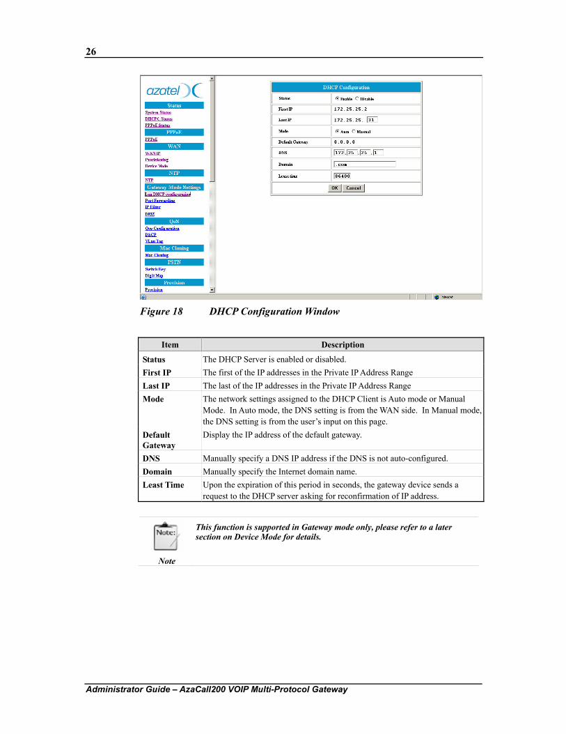
In DHCP Configuration menu, user can enable or disable the DHCP server’s dynamic IP address assignment function, which assigns an IP address to the user’s PC. Selecting Auto Mode allows 2 DNS server addresses to be assigned automatically. On the other hand the DNS address must be entered manually when the gateway device is configured to be in manual mode.
26
Administrator Guide – AzaCall200 VOIP Multi-Protocol Gateway
Figure 18 DHCP Configuration Window
Item Description
Status The DHCP Server is enabled or disabled. First IP The first of the IP addresses in the Private IP Address Range Last IP The last of the IP addresses in the Private IP Address Range Mode The network settings assigned to the DHCP Client is Auto mode or Manual
Mode. In Auto mode, the DNS setting is from the WAN side. In Manual mode, the DNS setting is from the user’s input on this page.
Default Gateway
Display the IP address of the default gateway.
DNS Manually specify a DNS IP address if the DNS is not auto-configured. Domain Manually specify the Internet domain name. Least Time Upon the expiration of this period in seconds, the gateway device sends a
request to the DHCP server asking for reconfirmation of IP address.
Note
This function is supported in Gateway mode only, please refer to a later section on Device Mode for details.
27
Administrator Guide – AzaCall200 VOIP Multi-Protocol Gateway
5.7.2. Port Forwarding
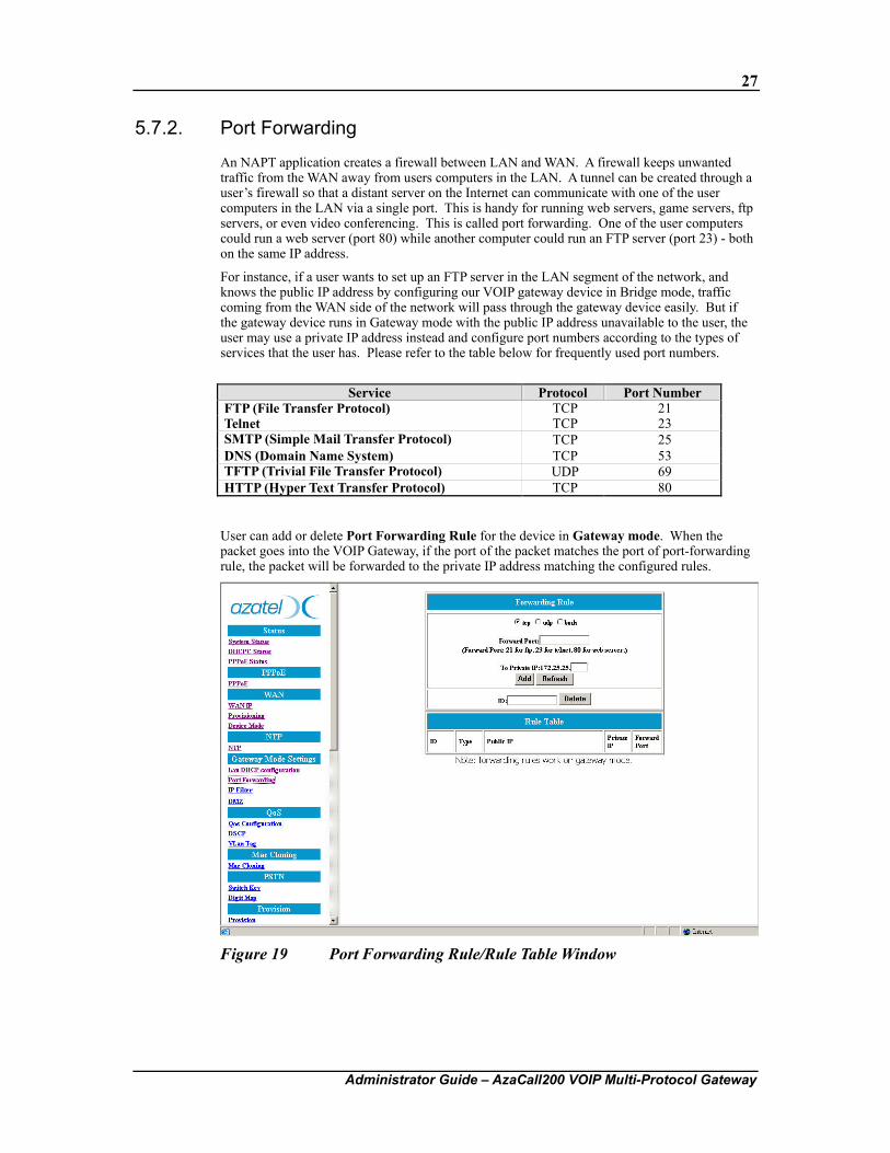
An NAPT application creates a firewall between LAN and WAN. A firewall keeps unwanted traffic from the WAN away from users computers in the LAN. A tunnel can be created through a user’s firewall so that a distant server on the Internet can communicate with one of the user computers in the LAN via a single port. This is handy for running web servers, game servers, ftp servers, or even video conferencing. This is called port forwarding. One of the user computers could run a web server (port 80) while another computer could run an FTP server (port 23) - both on the same IP address.
For instance, if a user wants to set up an FTP server in the LAN segment of the network, and knows the public IP address by configuring our VOIP gateway device in Bridge mode, traffic coming from the WAN side of the network will pass through the gateway device easily. But if the gateway device runs in Gateway mode with the public IP address unavailable to the user, the user may use a private IP address instead and configure port numbers according to the types of services that the user has. Please refer to the table below for frequently used port numbers.
Service Protocol Port Number
FTP (File Transfer Protocol) TCP 21 Telnet TCP 23 SMTP (Simple Mail Transfer Protocol) TCP 25 DNS (Domain Name System) TCP 53 TFTP (Trivial File Transfer Protocol) UDP 69 HTTP (Hyper Text Transfer Protocol) TCP 80
User can add or delete Port Forwarding Rule for the device in Gateway mode. When the packet goes into the VOIP Gateway, if the port of the packet matches the port of port-forwarding rule, the packet will be forwarded to the private IP address matching the configured rules.
Figure 19 Port Forwarding Rule/Rule Table Window
28
Administrator Guide – AzaCall200 VOIP Multi-Protocol Gateway
Item Description
tcp / udp / both Select if the user wants to forward the packets based on tcp, udp or both. Forward Port The port number of the tcp or udp packets the user wants to check against
the configured rules. To Private IP The IP Address of the user PC on the LAN-side network where packets of
matching criteria will be forwarded to. ID The ID of the port-forwarding rule in the Rule Table to be deleted.
5.7.3. IP Filter
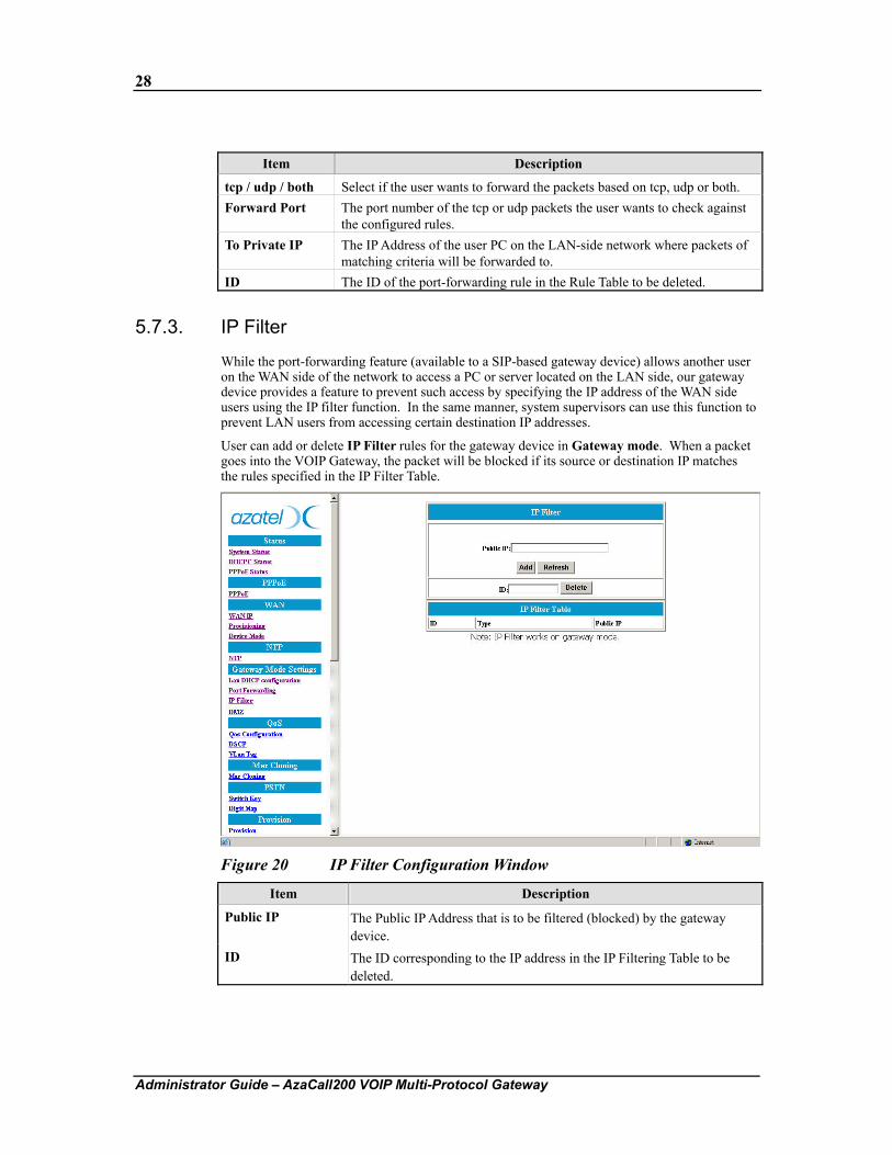
While the port-forwarding feature (available to a SIP-based gateway device) allows another user on the WAN side of the network to access a PC or server located on the LAN side, our gateway device provides a feature to prevent such access by specifying the IP address of the WAN side users using the IP filter function. In the same manner, system supervisors can use this function to prevent LAN users from accessing certain destination IP addresses.
User can add or delete IP Filter rules for the gateway device in Gateway mode. When a packet goes into the VOIP Gateway, the packet will be blocked if its source or destination IP matches the rules specified in the IP Filter Table.
Figure 20 IP Filter Configuration Window
Item Description
Public IP The Public IP Address that is to be filtered (blocked) by the gateway device.
ID The ID corresponding to the IP address in the IP Filtering Table to be deleted.
29
Administrator Guide – AzaCall200 VOIP Multi-Protocol Gateway
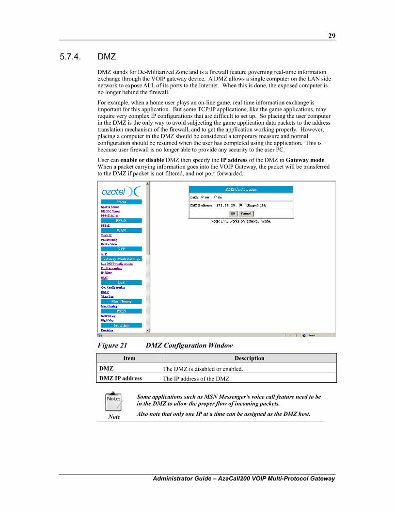
5.7.4. DMZ
DMZ stands for De-Militarized Zone and is a firewall feature governing real-time information exchange through the VOIP gateway device. A DMZ allows a single computer on the LAN side network to expose ALL of its ports to the Internet. When this is done, the exposed computer is no longer behind the firewall.
For example, when a home user plays an on-line game, real time information exchange is important for this application. But some TCP/IP applications, like the game applications, may require very complex IP configurations that are difficult to set up. So placing the user computer in the DMZ is the only way to avoid subjecting the game application data packets to the address translation mechanism of the firewall, and to get the application working properly. However, placing a computer in the DMZ should be considered a temporary measure and normal configuration should be resumed when the user has completed using the application. This is because user firewall is no longer able to provide any security to the user PC.
User can enable or disable DMZ then specify the IP address of the DMZ in Gateway mode. When a packet carrying information goes into the VOIP Gateway, the packet will be transferred to the DMZ if packet is not filtered, and not port-forwarded.
Figure 21 DMZ Configuration Window
Item Description
DMZ The DMZ is disabled or enabled. DMZ IP address The IP address of the DMZ.
Note
Some applications such as MSN Messenger’s voice call feature need to be in the DMZ to allow the proper flow of incoming packets.
Also note that only one IP at a time can be assigned as the DMZ host.
30
Administrator Guide – AzaCall200 VOIP Multi-Protocol Gateway
5.8. QoS
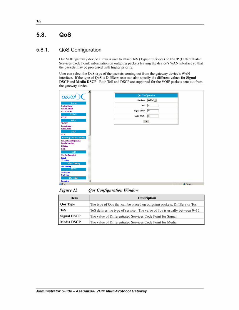
5.8.1. QoS Configuration
Our VOIP gateway device allows a user to attach ToS (Type of Service) or DSCP (Differentiated Services Code Point) information on outgoing packets leaving the device’s WAN interface so that the packets may be processed with higher priority.
User can select the QoS type of the packets coming out from the gateway device’s WAN interface. If the type of QoS is DiffServ, user can also specify the different values for Signal DSCP and Media DSCP. Both ToS and DSCP are supported for the VOIP packets sent out from the gateway device.
Figure 22 Qos Configuration Window
Item Description
Qos Type The type of Qos that can be placed on outgoing packets, DiffServ or Tos. ToS ToS defines the type of service. The value of Tos is usually between 0~15. Signal DSCP The value of Differentiated Services Code Point for Signal. Media DSCP The value of Differentiated Services Code Point for Media
31
Administrator Guide – AzaCall200 VOIP Multi-Protocol Gateway
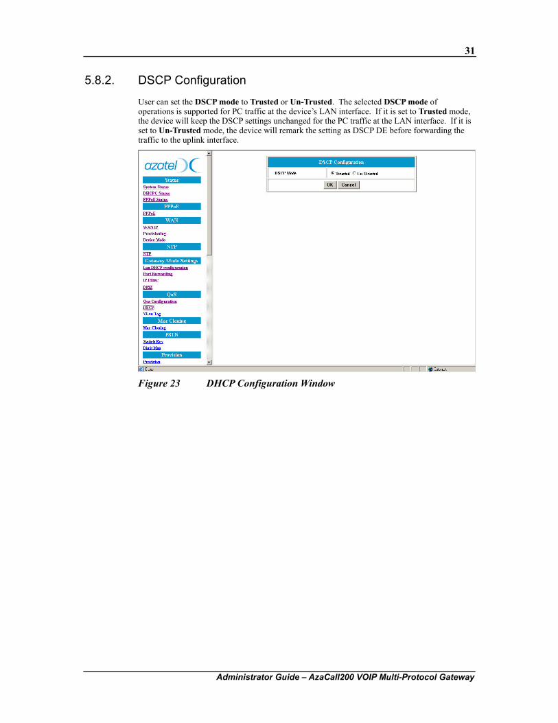
5.8.2. DSCP Configuration
User can set the DSCP mode to Trusted or Un-Trusted. The selected DSCP mode of operations is supported for PC traffic at the device’s LAN interface. If it is set to Trusted mode, the device will keep the DSCP settings unchanged for the PC traffic at the LAN interface. If it is set to Un-Trusted mode, the device will remark the setting as DSCP DE before forwarding the traffic to the uplink interface.
Figure 23 DHCP Configuration Window
32
Administrator Guide – AzaCall200 VOIP Multi-Protocol Gateway
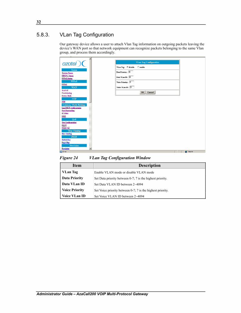
5.8.3. VLan Tag Configuration
Our gateway device allows a user to attach Vlan Tag information on outgoing packets leaving the device’s WAN port so that network equipment can recognize packets belonging to the same Vlan group, and process them accordingly.
Figure 24 VLan Tag Configuration Window
Item Description VLan Tag Enable VLAN mode or disable VLAN mode
Data Priority Set Data priority between 0-7; 7 is the highest priority.
Data VLan ID Set Data VLAN ID between 2~4094
Voice Priority Set Voice priority between 0-7; 7 is the highest priority.
Voice VLan ID Set Voice VLAN ID between 2~4094
33
Administrator Guide – AzaCall200 VOIP Multi-Protocol Gateway
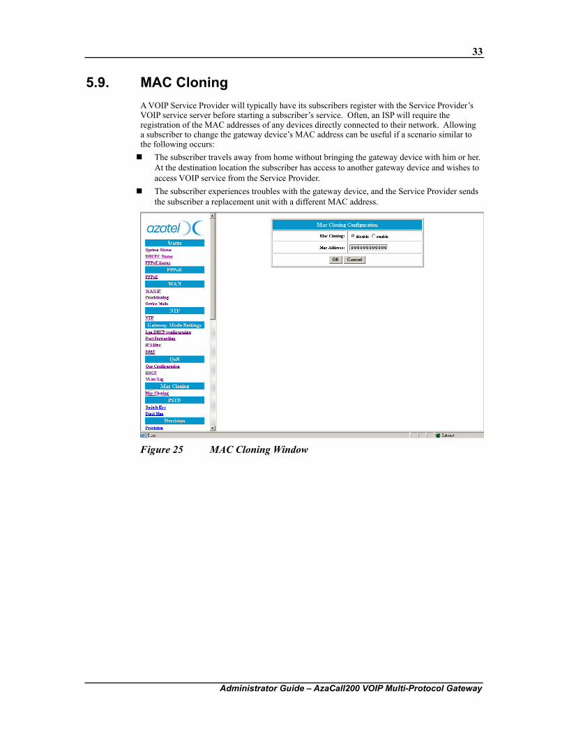
5.9. MAC Cloning A VOIP Service Provider will typically have its subscribers register with the Service Provider’s VOIP service server before starting a subscriber’s service. Often, an ISP will require the registration of the MAC addresses of any devices directly connected to their network. Allowing a subscriber to change the gateway device’s MAC address can be useful if a scenario similar to the following occurs: The subscriber travels away from home without bringing the gateway device with him or her.
At the destination location the subscriber has access to another gateway device and wishes to access VOIP service from the Service Provider.
The subscriber experiences troubles with the gateway device, and the Service Provider sends the subscriber a replacement unit with a different MAC address.
Figure 25 MAC Cloning Window
34
Administrator Guide – AzaCall200 VOIP Multi-Protocol Gateway
5.10. PSTN Configuration
5.10.1. Switch Key
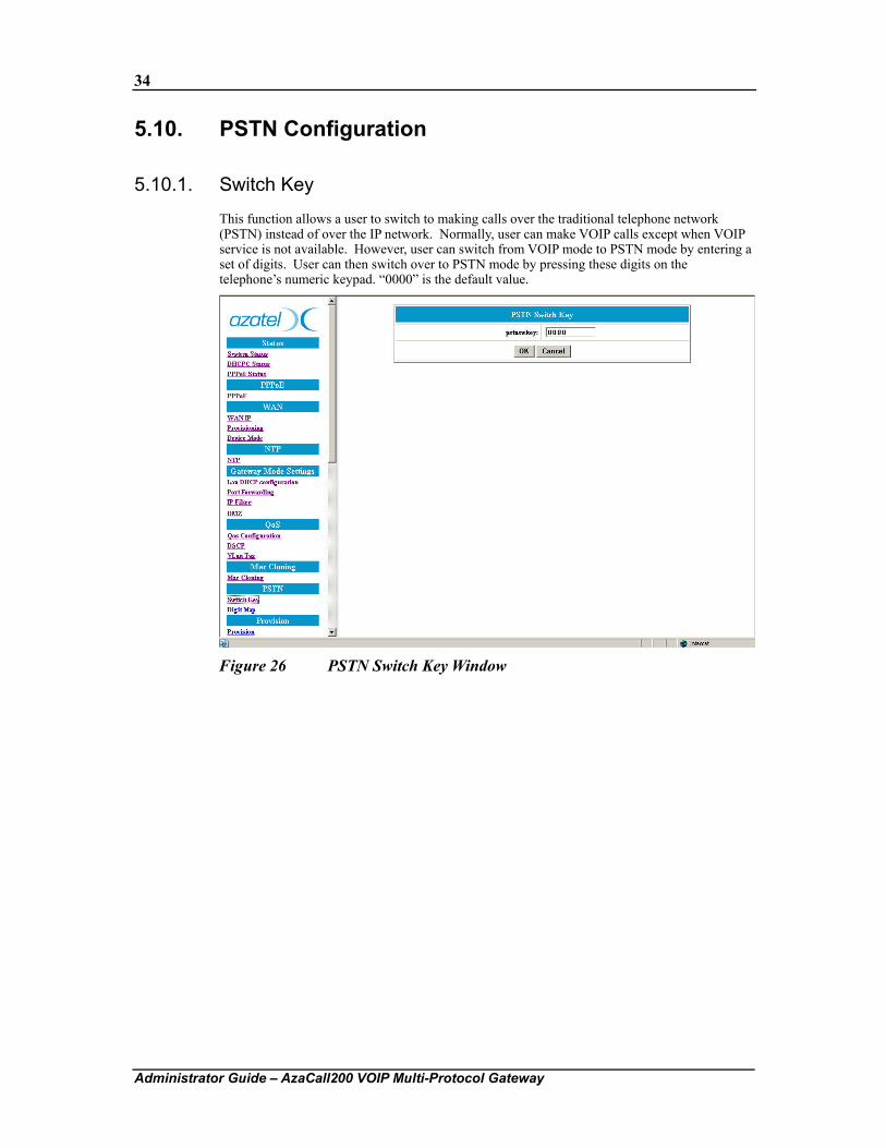
This function allows a user to switch to making calls over the traditional telephone network (PSTN) instead of over the IP network. Normally, user can make VOIP calls except when VOIP service is not available. However, user can switch from VOIP mode to PSTN mode by entering a set of digits. User can then switch over to PSTN mode by pressing these digits on the telephone’s numeric keypad. “0000” is the default value.
Figure 26 PSTN Switch Key Window
35
Administrator Guide – AzaCall200 VOIP Multi-Protocol Gateway
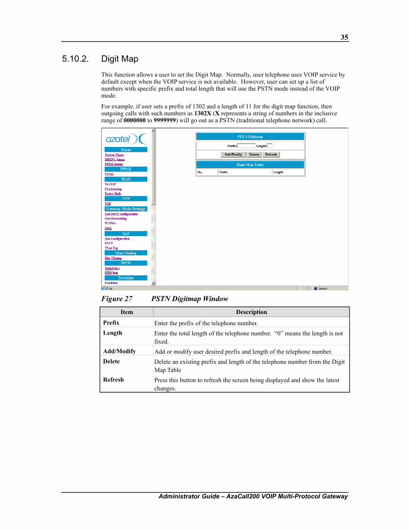
5.10.2. Digit Map
This function allows a user to set the Digit Map. Normally, user telephone uses VOIP service by default except when the VOIP service is not available. However, user can set up a list of numbers with specific prefix and total length that will use the PSTN mode instead of the VOIP mode.
For example, if user sets a prefix of 1302 and a length of 11 for the digit map function, then outgoing calls with such numbers as 1302X (X represents a string of numbers in the inclusive range of 0000000 to 9999999) will go out as a PSTN (traditional telephone network) call.
Figure 27 PSTN Digitmap Window
Item Description
Prefix Enter the prefix of the telephone number. Length Enter the total length of the telephone number. “0” means the length is not
fixed. Add/Modify Add or modify user desired prefix and length of the telephone number. Delete Delete an existing prefix and length of the telephone number from the Digit
Map Table Refresh Press this button to refresh the screen being displayed and show the latest
changes.
36
Administrator Guide – AzaCall200 VOIP Multi-Protocol Gateway
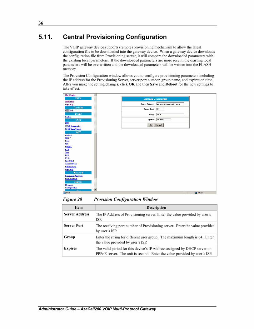
5.11. Central Provisioning Configuration The VOIP gateway device supports (remote) provisioning mechanism to allow the latest configuration file to be downloaded into the gateway device. When a gateway device downloads the configuration file from Provisioning server, it will compare the downloaded parameters with the existing local parameters. If the downloaded parameters are more recent, the existing local parameters will be overwritten and the downloaded parameters will be written into the FLASH memory.
The Provision Configuration window allows you to configure provisioning parameters including the IP address for the Provisioning Server, server port number, group name, and expiration time. After you make the setting changes, click OK and then Save and Reboot for the new settings to take effect.
Figure 28 Provision Configuration Window
Item Description
Server Address The IP Address of Provisioning server. Enter the value provided by user’s ISP.
Server Port The receiving port number of Provisioning server. Enter the value provided by user’s ISP.
Group Enter the string for different user group. The maximum length is 64. Enter the value provided by user’s ISP.
Expires The valid period for this device’s IP Address assigned by DHCP server or PPPoE server. The unit is second. Enter the value provided by user’s ISP.
37
Administrator Guide – AzaCall200 VOIP Multi-Protocol Gateway
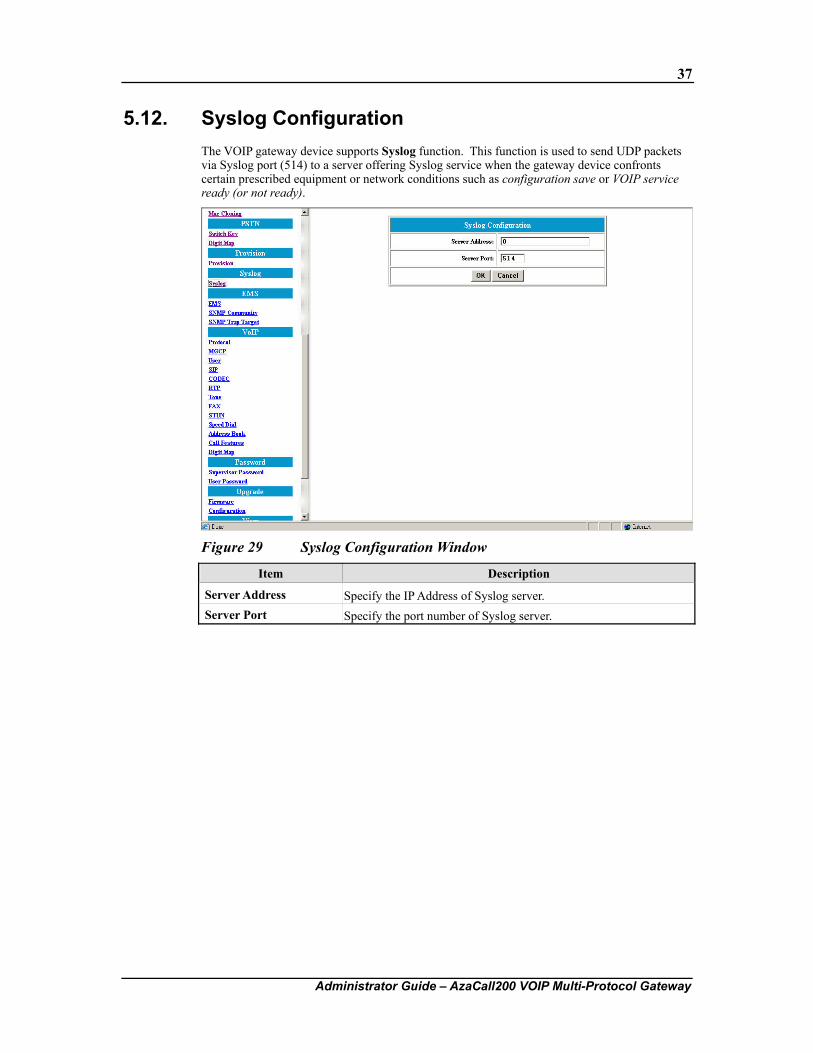
5.12. Syslog Configuration The VOIP gateway device supports Syslog function. This function is used to send UDP packets via Syslog port (514) to a server offering Syslog service when the gateway device confronts certain prescribed equipment or network conditions such as configuration save or VOIP service ready (or not ready).
Figure 29 Syslog Configuration Window
Item Description
Server Address Specify the IP Address of Syslog server. Server Port Specify the port number of Syslog server.
38
Administrator Guide – AzaCall200 VOIP Multi-Protocol Gateway
5.13. EMS Configuration
5.13.1. EMS
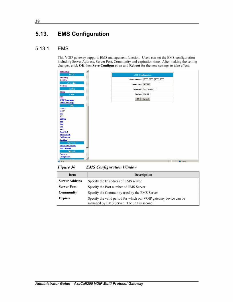
This VOIP gateway supports EMS management function. Users can set the EMS configuration including Server Address, Server Port, Community and expiration time. After making the setting changes, click OK then Save Configuration and Reboot for the new settings to take effect.
Figure 30 EMS Configuration Window
Item Description
Server Address Specify the IP address of EMS server Server Port Specify the Port number of EMS Server Community Specify the Community used by the EMS Server Expires Specify the valid period for which our VOIP gateway device can be
managed by EMS Server. The unit is second.
39
Administrator Guide – AzaCall200 VOIP Multi-Protocol Gateway
5.13.2. SNMP Community Configuration
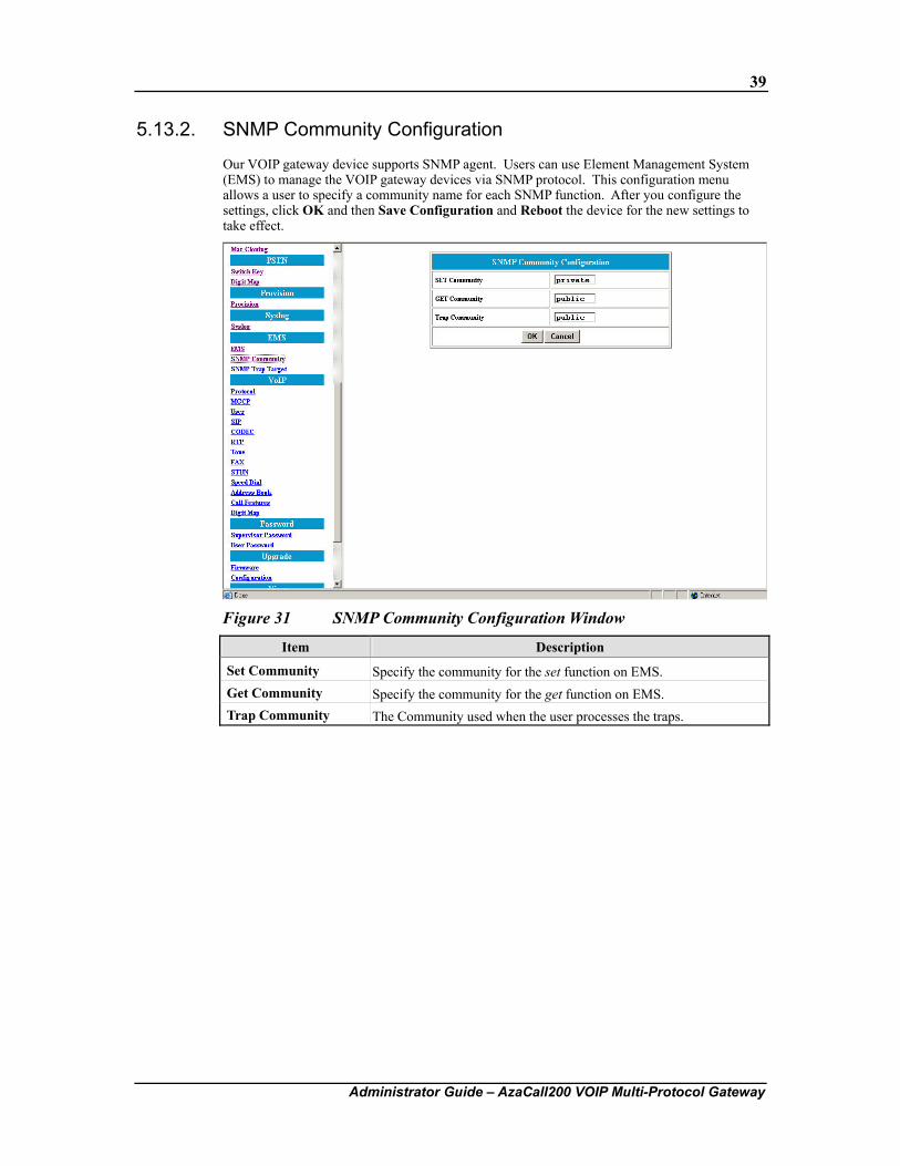
Our VOIP gateway device supports SNMP agent. Users can use Element Management System (EMS) to manage the VOIP gateway devices via SNMP protocol. This configuration menu allows a user to specify a community name for each SNMP function. After you configure the settings, click OK and then Save Configuration and Reboot the device for the new settings to take effect.
Figure 31 SNMP Community Configuration Window
Item Description
Set Community Specify the community for the set function on EMS. Get Community Specify the community for the get function on EMS. Trap Community The Community used when the user processes the traps.
40
Administrator Guide – AzaCall200 VOIP Multi-Protocol Gateway
5.13.3. SNMP Trap Target
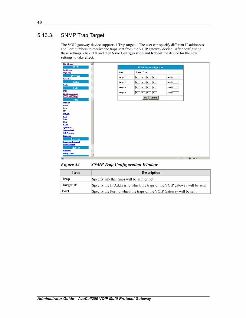
The VOIP gateway device supports 4 Trap targets. The user can specify different IP addresses and Port numbers to receive the traps sent from the VOIP gateway device. After configuring these settings, click OK and then Save Configuration and Reboot the device for the new settings to take effect.
Figure 32 SNMP Trap Configuration Window
Item Description
Trap Specify whether traps will be sent or not. Target IP Specify the IP Address to which the traps of the VOIP gateway will be sent. Port Specify the Port to which the traps of the VOIP Gateway will be sent.
41
Administrator Guide – AzaCall200 VOIP Multi-Protocol Gateway
5.14. VOIP Configuration
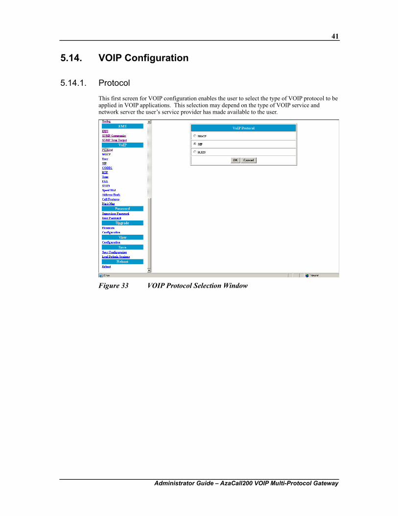
5.14.1. Protocol
This first screen for VOIP configuration enables the user to select the type of VOIP protocol to be applied in VOIP applications. This selection may depend on the type of VOIP service and network server the user’s service provider has made available to the user.
Figure 33 VOIP Protocol Selection Window
42
Administrator Guide – AzaCall200 VOIP Multi-Protocol Gateway
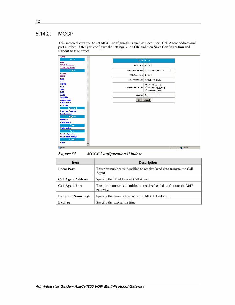
5.14.2. MGCP
This screen allows you to set MGCP configurations such as Local Port, Call Agent address and port number. After you configure the settings, click OK and then Save Configuration and Reboot to take effect.
Figure 34 MGCP Configuration Window
Item Description
Local Port This port number is identified to receive/send data from/to the Call Agent
Call Agent Address Specify the IP address of Call Agent
Call Agent Port The port number is identified to receive/send data from/to the VoIP gateway.
Endpoint Name Style Specify the naming format of the MGCP Endpoint.
Expires Specify the expiration time
43
Administrator Guide – AzaCall200 VOIP Multi-Protocol Gateway
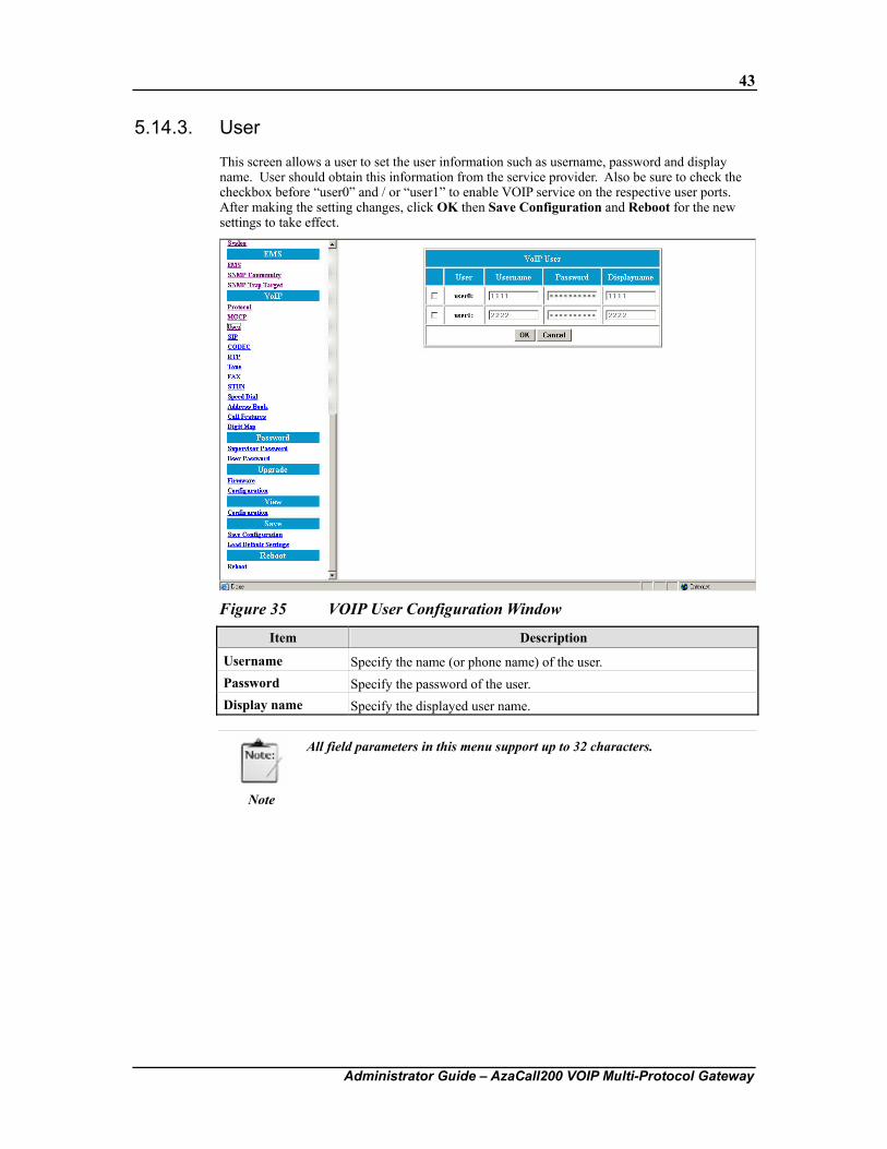
5.14.3. User
This screen allows a user to set the user information such as username, password and display name. User should obtain this information from the service provider. Also be sure to check the checkbox before “user0” and / or “user1” to enable VOIP service on the respective user ports. After making the setting changes, click OK then Save Configuration and Reboot for the new settings to take effect.
Figure 35 VOIP User Configuration Window
Item Description
Username Specify the name (or phone name) of the user. Password Specify the password of the user. Display name Specify the displayed user name.
Note
All field parameters in this menu support up to 32 characters.
44
Administrator Guide – AzaCall200 VOIP Multi-Protocol Gateway
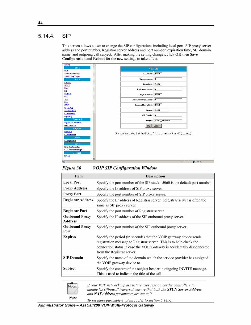
5.14.4. SIP
This screen allows a user to change the SIP configurations including local port, SIP proxy server address and port number, Registrar server address and port number, expiration time, SIP domain name, and outgoing call subject. After making the setting changes, click OK then Save Configuration and Reboot for the new settings to take effect.
Figure 36 VOIP SIP Configuration Window
Item Description Local Port Specify the port number of the SIP stack. 5060 is the default port number. Proxy Address Specify the IP address of SIP proxy server. Proxy Port Specify the port number of SIP proxy server. Registrar Address Specify the IP address of Registrar server. Registrar server is often the
same as SIP proxy server. Registrar Port Specify the port number of Registrar server. Outbound Proxy Address
Specify the IP address of the SIP outbound proxy server.
Outbound Proxy Port
Specify the port number of the SIP outbound proxy server.
Expires Specify the period (in seconds) that the VOIP gateway device sends registration message to Registrar server. This is to help check the connection status in case the VOIP Gateway is accidentally disconnected from the Registrar server.
SIP Domain Specify the name of the domain which the service provider has assigned the VOIP gateway device to.
Subject Specify the content of the subject header in outgoing INVITE message. This is used to indicate the title of the call.
Note
If your VoIP network infrastructure uses session border controllers to handle NAT/firewall traversal, ensure that both the STUN Server Address and NAT Address parameters are set to 0.
To set these parameters, please refer to section 5.14.9.

45
Administrator Guide – AzaCall200 VOIP Multi-Protocol Gateway
5.14.5. CODEC
This screen allows a user to set CODEC configurations including Codec Rate, Preferred Codec, and VAD. After making the setting changes, click OK then Save Configuration and Reboot for the new settings to take effect.
Figure 37 VOIP Codec Configuration Window
Item Description
CODEC Rate “CODEC rate” specifies the packetization time (in milliseconds). This value is from 10 to 30
Preferred CODEC Specify the preferred method of voice compression. G..711A and G..711U: 40Kbps G.729A: 24Kbps G.723.1: 12Kbps
VAD Voice Activity Detection feature. Enable: Send packets only when the user is speaking. This will save
the bandwidth but cause some time delay. Disabled: Send packets whether the user is speaking or not. This
will improve the voice quality but increase traffic load.
46
Administrator Guide – AzaCall200 VOIP Multi-Protocol Gateway
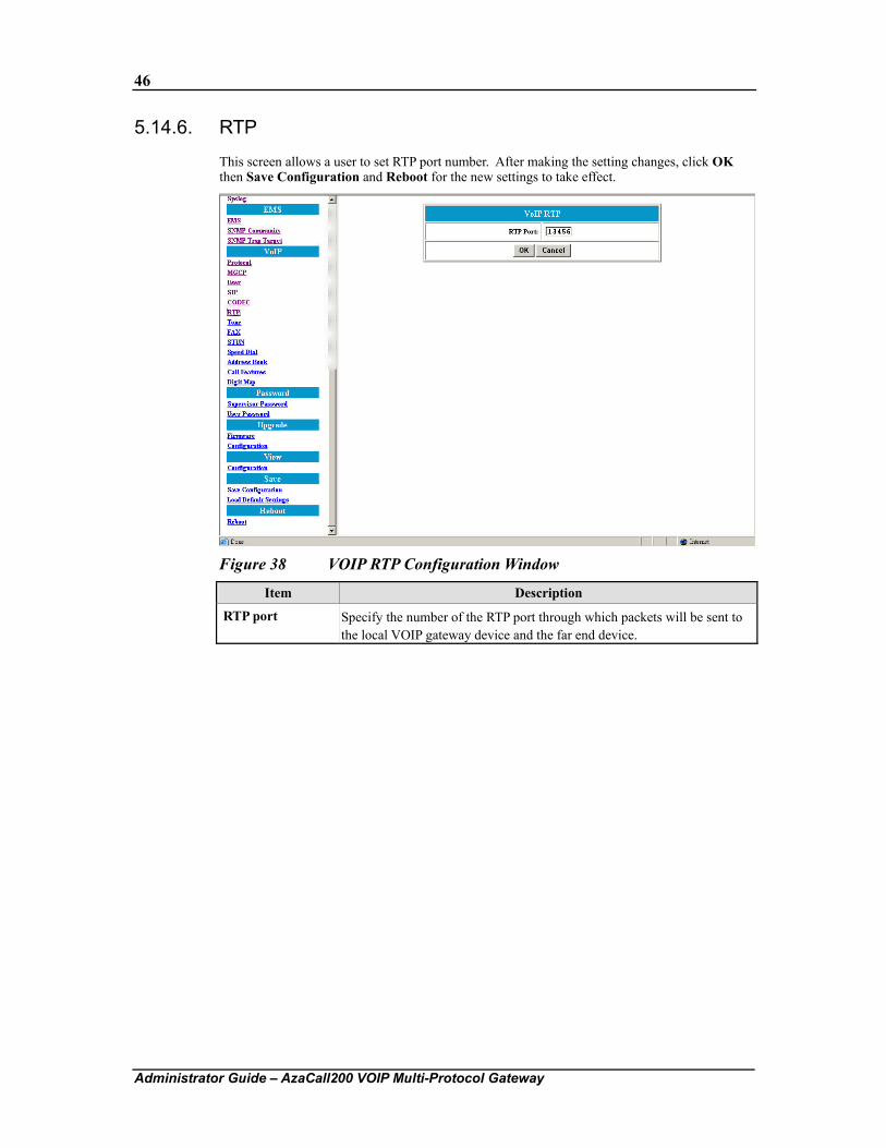
5.14.6. RTP
This screen allows a user to set RTP port number. After making the setting changes, click OK then Save Configuration and Reboot for the new settings to take effect.
Figure 38 VOIP RTP Configuration Window
Item Description
RTP port Specify the number of the RTP port through which packets will be sent to the local VOIP gateway device and the far end device.
47
Administrator Guide – AzaCall200 VOIP Multi-Protocol Gateway
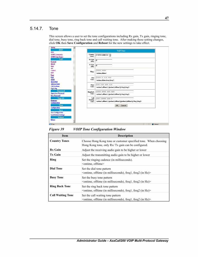
5.14.7. Tone
This screen allows a user to set the tone configurations including Rx gain, Tx gain, ringing tone, dial tone, busy tone, ring back tone and call waiting tone. After making these setting changes, click OK then Save Configuration and Reboot for the new settings to take effect.
Figure 39 VOIP Tone Configuration Window
Item Description
Country Tones Choose Hong Kong tone or customer specified tone. When choosing Hong Kong tone, only Rx/ Tx gain can be configured.
Rx Gain Adjust the receiving audio gain to be higher or lower Tx Gain Adjust the transmitting audio gain to be higher or lower Ring Set the ringing cadence (in milliseconds).
<ontime, offtime> Dial Tone Set the dial tone pattern
<ontime, offtime (in milliseconds), freq1, freq2 (in Hz)> Busy Tone Set the busy tone pattern
<ontime, offtime (in milliseconds), freq1, freq2 (in Hz)> Ring Back Tone Set the ring back tone pattern
<ontime, offtime (in milliseconds), freq1, freq2 (in Hz)> Call Waiting Tone Set the call waiting tone pattern
<ontime, offtime (in milliseconds), freq1, freq2 (in Hz)>
48
Administrator Guide – AzaCall200 VOIP Multi-Protocol Gateway
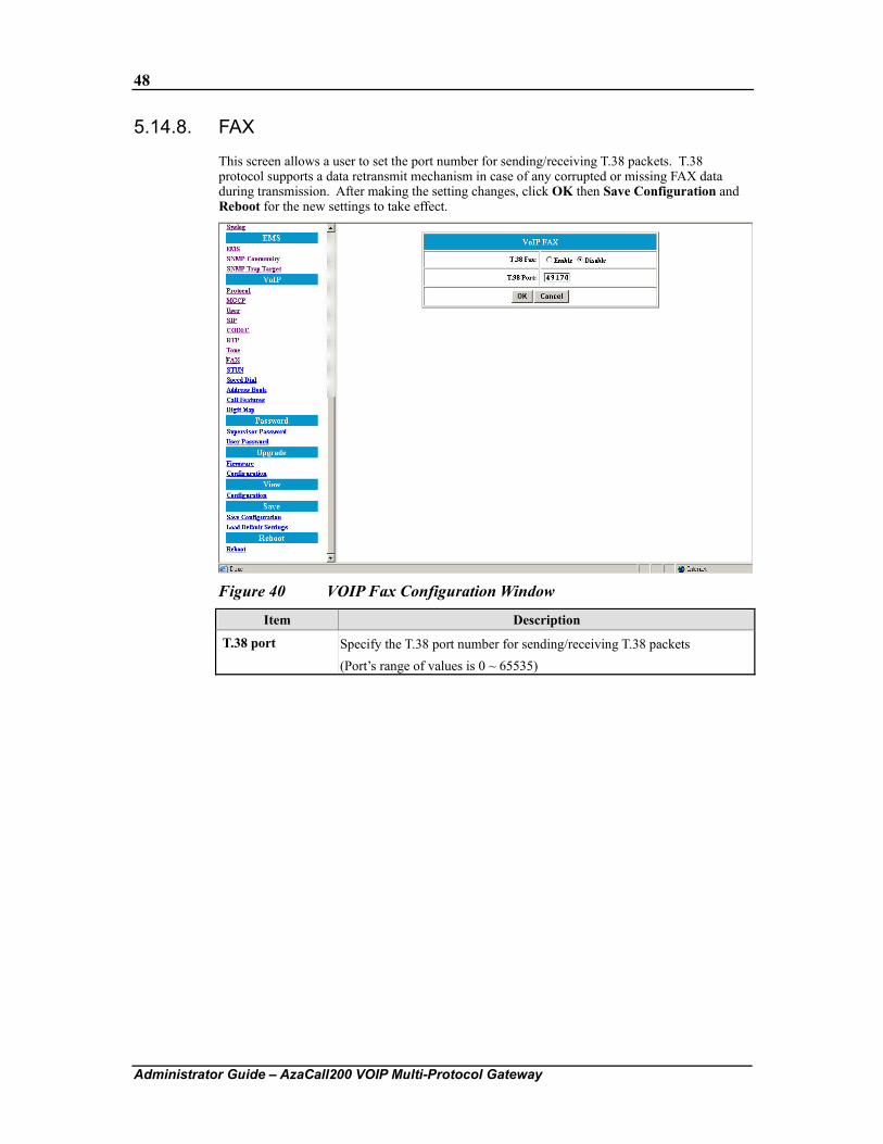
5.14.8. FAX
This screen allows a user to set the port number for sending/receiving T.38 packets. T.38 protocol supports a data retransmit mechanism in case of any corrupted or missing FAX data during transmission. After making the setting changes, click OK then Save Configuration and Reboot for the new settings to take effect.
Figure 40 VOIP Fax Configuration Window
Item Description
T.38 port Specify the T.38 port number for sending/receiving T.38 packets (Port’s range of values is 0 ~ 65535)
49
Administrator Guide – AzaCall200 VOIP Multi-Protocol Gateway
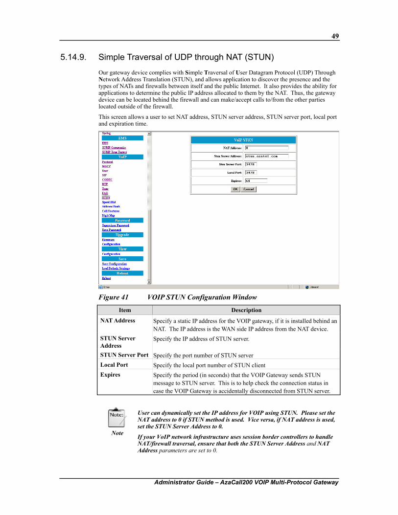
5.14.9. Simple Traversal of UDP through NAT (STUN)
Our gateway device complies with Simple Traversal of User Datagram Protocol (UDP) Through Network Address Translation (STUN), and allows application to discover the presence and the types of NATs and firewalls between itself and the public Internet. It also provides the ability for applications to determine the public IP address allocated to them by the NAT. Thus, the gateway device can be located behind the firewall and can make/accept calls to/from the other parties located outside of the firewall.
This screen allows a user to set NAT address, STUN server address, STUN server port, local port and expiration time.
Figure 41 VOIP STUN Configuration Window
Item Description
NAT Address Specify a static IP address for the VOIP gateway, if it is installed behind an NAT. The IP address is the WAN side IP address from the NAT device.
STUN Server Address
Specify the IP address of STUN server.
STUN Server Port Specify the port number of STUN server Local Port Specify the local port number of STUN client Expires Specify the period (in seconds) that the VOIP Gateway sends STUN
message to STUN server. This is to help check the connection status in case the VOIP Gateway is accidentally disconnected from STUN server.
Note
User can dynamically set the IP address for VOIP using STUN. Please set the NAT address to 0 if STUN method is used. Vice versa, if NAT address is used, set the STUN Server Address to 0.
If your VoIP network infrastructure uses session border controllers to handle NAT/firewall traversal, ensure that both the STUN Server Address and NAT Address parameters are set to 0.
50
Administrator Guide – AzaCall200 VOIP Multi-Protocol Gateway
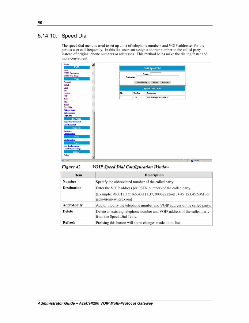
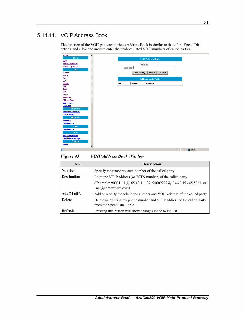
5.14.10. Speed Dial
The speed dial menu is used to set up a list of telephone numbers and VOIP addresses for the parties user call frequently. In this list, user can assign a shorter number to the called party instead of original phone numbers or addresses. This method helps make the dialing faster and more convenient.
Figure 42 VOIP Speed Dial Configuration Window
Item Description
Number Specify the abbreviated number of the called party. Destination Enter the VOIP address (or PSTN number) of the called party.
(Example: [email protected], [email protected]:5061, or [email protected])
Add/Modify Add or modify the telephone number and VOIP address of the called party.Delete Delete an existing telephone number and VOIP address of the called party
from the Speed Dial Table. Refresh Pressing this button will show changes made to the list.
51
Administrator Guide – AzaCall200 VOIP Multi-Protocol Gateway
5.14.11. VOIP Address Book
The function of the VOIP gateway device’s Address Book is similar to that of the Speed Dial entries, and allow the users to enter the unabbreviated VOIP numbers of called parties.
Figure 43 VOIP Address Book Window
Item Description
Number Specify the unabbreviated number of the called party. Destination Enter the VOIP address (or PSTN number) of the called party
(Example: [email protected], [email protected]:5061, or [email protected])
Add/Modify Add or modify the telephone number and VOIP address of the called party.Delete Delete an existing telephone number and VOIP address of the called party
from the Speed Dial Table. Refresh Pressing this button will show changes made to the list.
52
Administrator Guide – AzaCall200 VOIP Multi-Protocol Gateway
5.14.12. Call Features
The AzaCall200 gateway device supports several call features. Before getting into the configuration procedures, the handshaking protocol steps of these call features are illustrated using the figures below:
Call features can be handled by the AzaCall200 in two ways: Keypad sequence (ex: Flash, #25) or with a hook flash sequence, similar to many traditional PSTN services such as 3-way calling, and call waiting.
To enable the use of hook flash for call feature use, please log in to the CLI as supervisor and enter the following commands:
To enable the use of hook flash sequences to call features:
debug config active set voip_callfeature_enable 0
debug config flash set voip_callfeature_enable 0
save
reboot
To enable the use of keypad sequences for call features:
debug config active set voip_callfeature_enable 1
debug config flash set voip_callfeature_enable 1
save
reboot
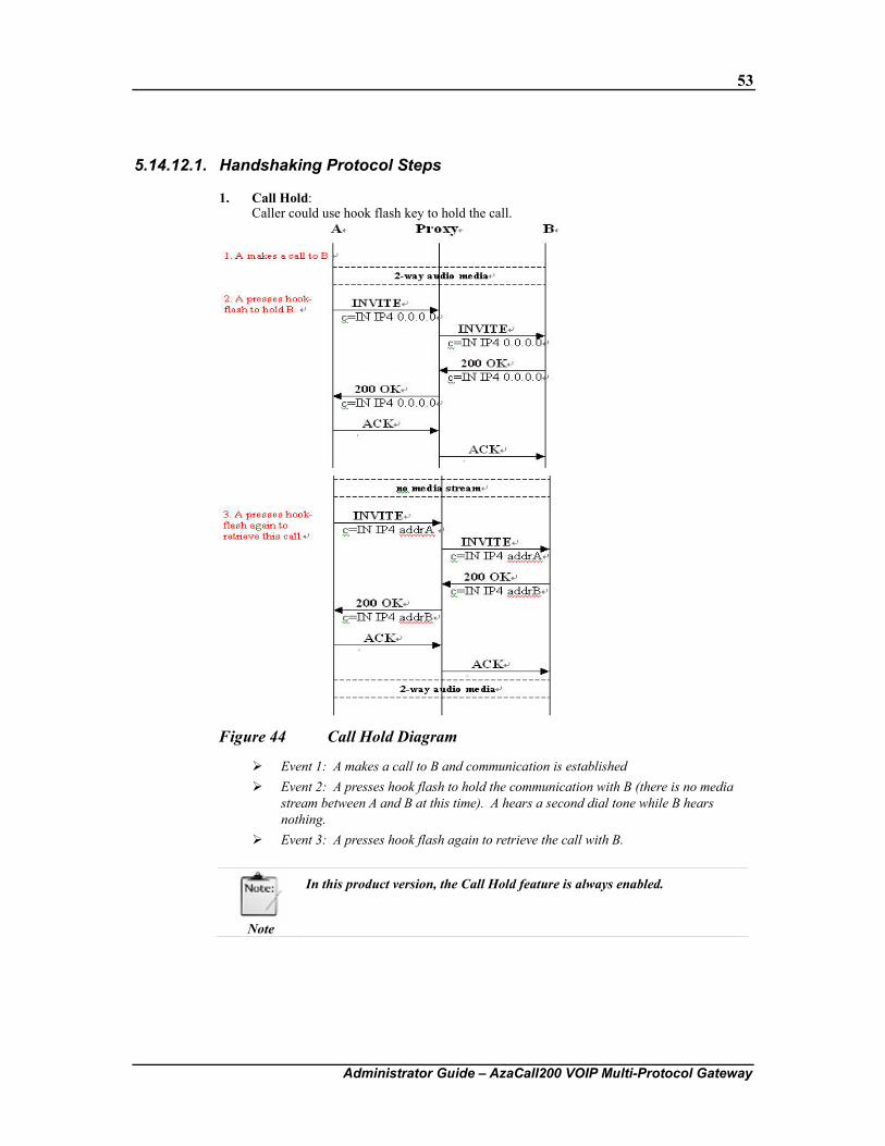
53
Administrator Guide – AzaCall200 VOIP Multi-Protocol Gateway
5.14.12.1. Handshaking Protocol Steps
1. Call Hold: Caller could use hook flash key to hold the call.
Figure 44 Call Hold Diagram
Event 1: A makes a call to B and communication is established Event 2: A presses hook flash to hold the communication with B (there is no media
stream between A and B at this time). A hears a second dial tone while B hears nothing.
Event 3: A presses hook flash again to retrieve the call with B.
Note
In this product version, the Call Hold feature is always enabled.
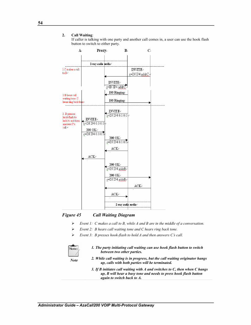
54
Administrator Guide – AzaCall200 VOIP Multi-Protocol Gateway
2. Call Waiting: If caller is talking with one party and another call comes in, a user can use the hook flash button to switch to either party.
Figure 45 Call Waiting Diagram
Event 1: C makes a call to B, while A and B are in the middle of a conversation. Event 2: B hears call waiting tone and C hears ring back tone. Event 3: B presses hook-flash to hold A and then answers C’s call.
Note
1. The party initiating call waiting can use hook flash button to switch between two other parties.
2. While call waiting is in progress, but the call waiting originator hangs up, calls with both parties will be terminated.
3. If B initiates call waiting with A and switches to C, then when C hangs up, B will hear a busy tone and needs to press hook flash button again to switch back to A.
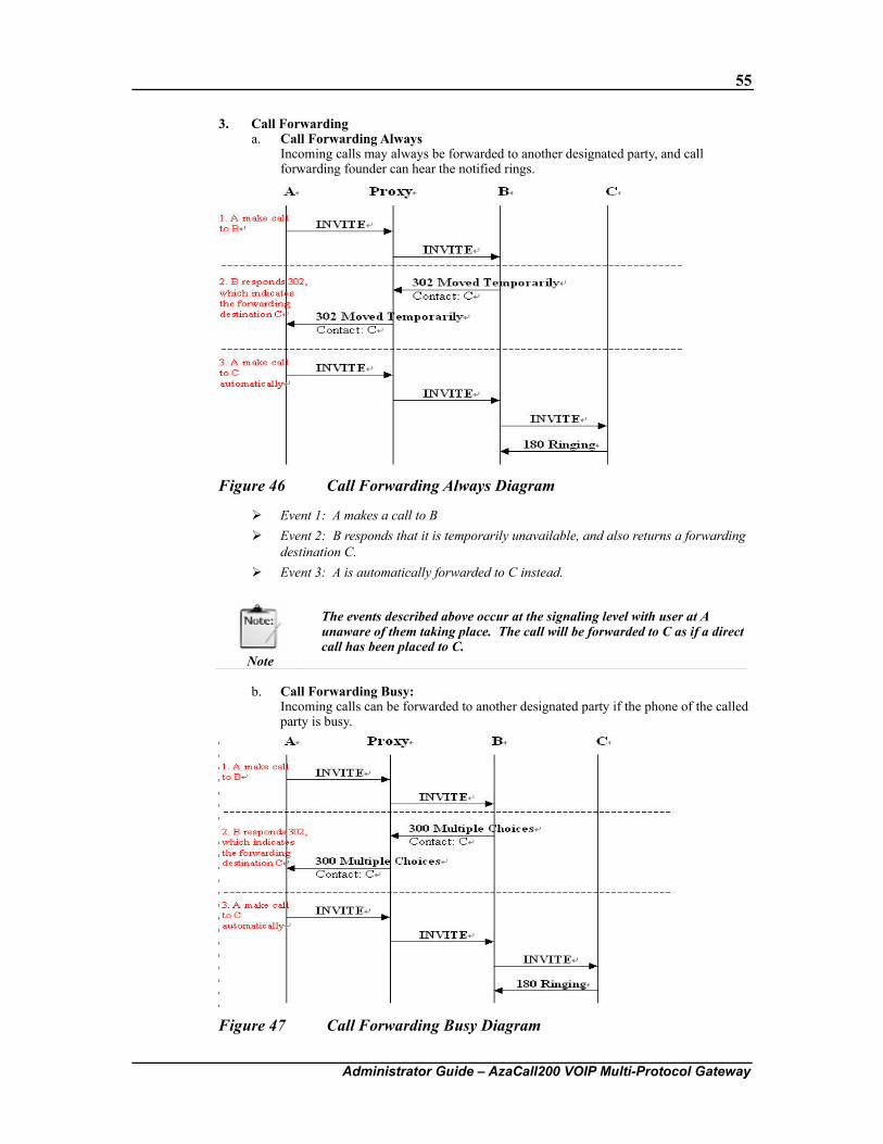
55
Administrator Guide – AzaCall200 VOIP Multi-Protocol Gateway
3. Call Forwarding a. Call Forwarding Always
Incoming calls may always be forwarded to another designated party, and call forwarding founder can hear the notified rings.
Figure 46 Call Forwarding Always Diagram
Event 1: A makes a call to B Event 2: B responds that it is temporarily unavailable, and also returns a forwarding
destination C. Event 3: A is automatically forwarded to C instead.
Note
The events described above occur at the signaling level with user at A unaware of them taking place. The call will be forwarded to C as if a direct call has been placed to C.
b. Call Forwarding Busy:
Incoming calls can be forwarded to another designated party if the phone of the called party is busy.
Figure 47 Call Forwarding Busy Diagram
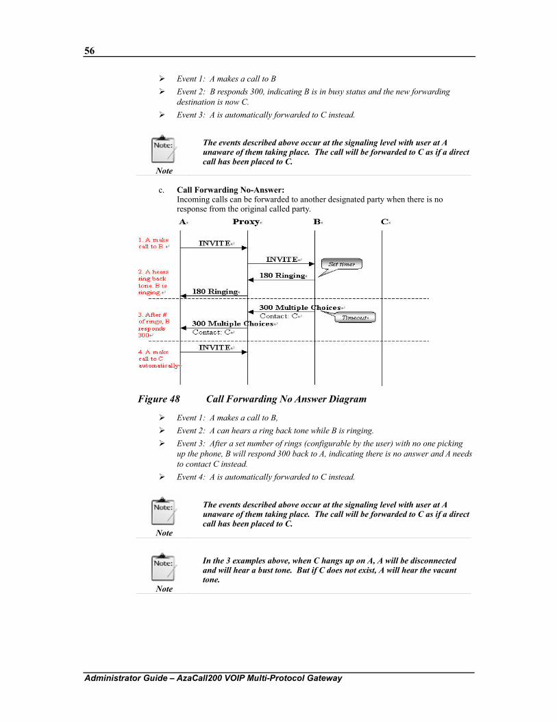
56
Administrator Guide – AzaCall200 VOIP Multi-Protocol Gateway
Event 1: A makes a call to B Event 2: B responds 300, indicating B is in busy status and the new forwarding
destination is now C. Event 3: A is automatically forwarded to C instead.
Note
The events described above occur at the signaling level with user at A unaware of them taking place. The call will be forwarded to C as if a direct call has been placed to C.
c. Call Forwarding No-Answer:
Incoming calls can be forwarded to another designated party when there is no response from the original called party.
Figure 48 Call Forwarding No Answer Diagram
Event 1: A makes a call to B, Event 2: A can hears a ring back tone while B is ringing. Event 3: After a set number of rings (configurable by the user) with no one picking
up the phone, B will respond 300 back to A, indicating there is no answer and A needs to contact C instead.
Event 4: A is automatically forwarded to C instead.
Note
The events described above occur at the signaling level with user at A unaware of them taking place. The call will be forwarded to C as if a direct call has been placed to C.
Note
In the 3 examples above, when C hangs up on A, A will be disconnected and will hear a bust tone. But if C does not exist, A will hear the vacant tone.
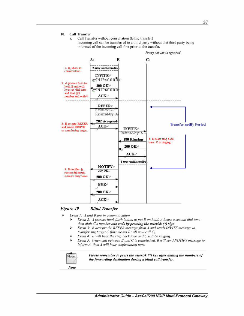
57
Administrator Guide – AzaCall200 VOIP Multi-Protocol Gateway
10. Call Transfer a. Call Transfer without consultation (Blind transfer)
Incoming call can be transferred to a third party without that third party being informed of the incoming call first prior to the transfer.
Figure 49 Blind Transfer Event 1: A and B are in communication
Event 2: A presses hook flash button to put B on hold; A hears a second dial tone then dials C’s number and ends by pressing the asterisk (*) sign.
Event 3: B accepts the REFER message from A and sends INVITE message to transferring target C (this means B will now call C).
Event 4: B will hear the ring back tone and C will be ringing. Event 5: When call between B and C is established, B will send NOTIFY message to
inform A, then A will hear confirmation tone.
Note
Please remember to press the asterisk (*) key after dialing the numbers of the forwarding destination during a blind call transfer.
Transfer notify Period
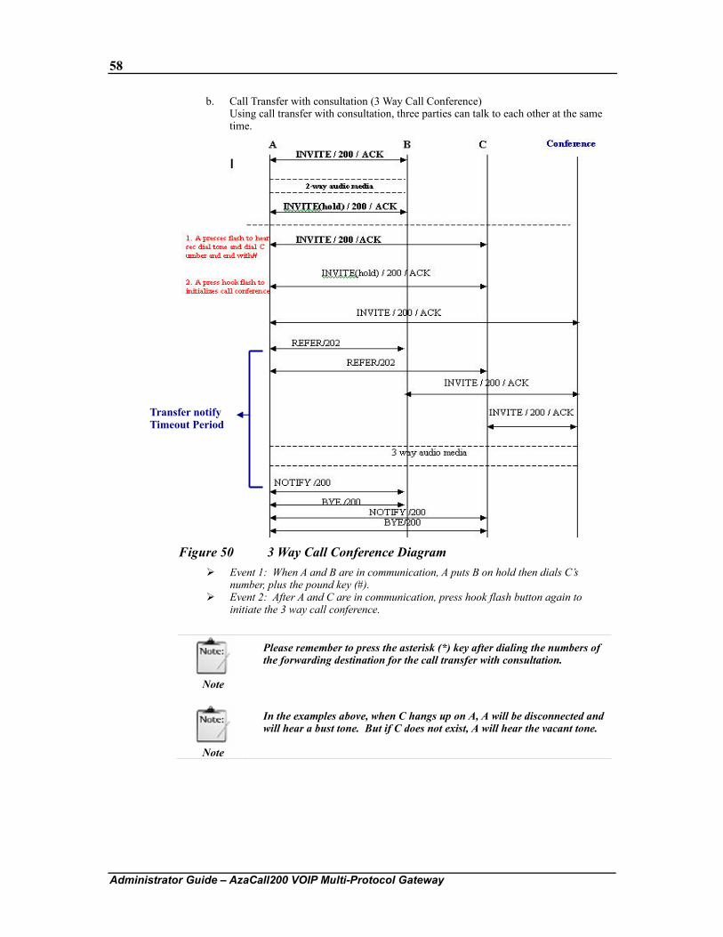
58
Administrator Guide – AzaCall200 VOIP Multi-Protocol Gateway
b. Call Transfer with consultation (3 Way Call Conference) Using call transfer with consultation, three parties can talk to each other at the same time.
Figure 50 3 Way Call Conference Diagram Event 1: When A and B are in communication, A puts B on hold then dials C’s
number, plus the pound key (#). Event 2: After A and C are in communication, press hook flash button again to
initiate the 3 way call conference.
Note
Please remember to press the asterisk (*) key after dialing the numbers of the forwarding destination for the call transfer with consultation.
Note
In the examples above, when C hangs up on A, A will be disconnected and will hear a bust tone. But if C does not exist, A will hear the vacant tone.
Transfer notify Timeout Period
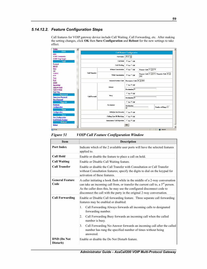
59
Administrator Guide – AzaCall200 VOIP Multi-Protocol Gateway
5.14.12.2. Feature Configuration Steps
Call features for VOIP gateway device include Call Waiting, Call Forwarding, etc. After making the setting changes, click OK then Save Configuration and Reboot for the new settings to take effect.
Figure 51 VOIP Call Feature Configuration Window
Item Description
Port Index Indicate which of the 2 available user ports will have the selected features applied to.
Call Hold Enable or disable the feature to place a call on hold. Call Waiting Enable or Disable Call Waiting feature. Call Transfer Enable or disable the Call Transfer with Consultation or Call Transfer
without Consultation features; specify the digits to dial on the keypad for activation of these features.
General Feature Code
A caller initiating a hook flash while in the middle of a 2-way conversation can take an incoming call from, or transfer the current call to, a 3rd person. As the caller does this, he may use the configured disconnect code to disconnect the call with the party in the original 2-way conversation.
Call Forwarding Enable or Disable Call forwarding feature. Three separate call forwarding features may be enabled or disabled: 1. Call Forwarding Always forwards all incoming calls to designated
forwarding number. 2. Call Forwarding Busy forwards an incoming call when the called
number is busy. 3. Call Forwarding No-Answer forwards an incoming call after the called
number has rung the specified number of times without being answered.
DND (Do Not Disturb)
Enable or disable the Do Not Disturb feature.
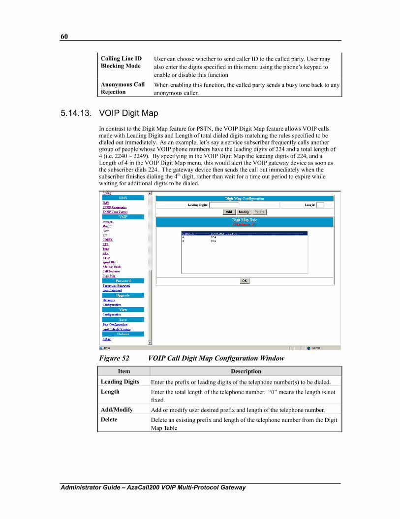
60
Administrator Guide – AzaCall200 VOIP Multi-Protocol Gateway
Calling Line ID Blocking Mode
User can choose whether to send caller ID to the called party. User may also enter the digits specified in this menu using the phone’s keypad to enable or disable this function
Anonymous Call Rejection
When enabling this function, the called party sends a busy tone back to any anonymous caller.
5.14.13. VOIP Digit Map
In contrast to the Digit Map feature for PSTN, the VOIP Digit Map feature allows VOIP calls made with Leading Digits and Length of total dialed digits matching the rules specified to be dialed out immediately. As an example, let’s say a service subscriber frequently calls another group of people whose VOIP phone numbers have the leading digits of 224 and a total length of 4 (i.e. 2240 ~ 2249). By specifying in the VOIP Digit Map the leading digits of 224, and a Length of 4 in the VOIP Digit Map menu, this would alert the VOIP gateway device as soon as the subscriber dials 224. The gateway device then sends the call out immediately when the subscriber finishes dialing the 4th digit, rather than wait for a time out period to expire while waiting for additional digits to be dialed.
Figure 52 VOIP Call Digit Map Configuration Window
Item Description
Leading Digits Enter the prefix or leading digits of the telephone number(s) to be dialed. Length Enter the total length of the telephone number. “0” means the length is not
fixed. Add/Modify Add or modify user desired prefix and length of the telephone number. Delete Delete an existing prefix and length of the telephone number from the Digit
Map Table
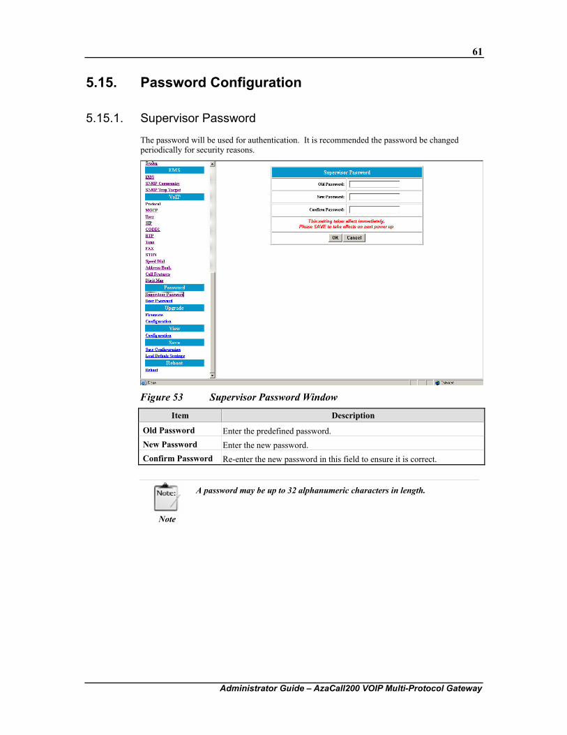
61
Administrator Guide – AzaCall200 VOIP Multi-Protocol Gateway
5.15. Password Configuration
5.15.1. Supervisor Password
The password will be used for authentication. It is recommended the password be changed periodically for security reasons.
Figure 53 Supervisor Password Window
Item Description
Old Password Enter the predefined password. New Password Enter the new password. Confirm Password Re-enter the new password in this field to ensure it is correct.
Note
A password may be up to 32 alphanumeric characters in length.
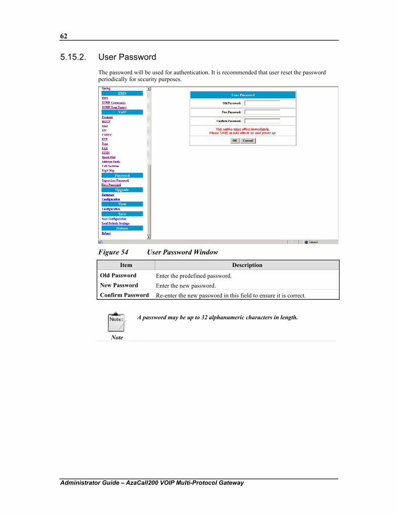
62
Administrator Guide – AzaCall200 VOIP Multi-Protocol Gateway
5.15.2. User Password
The password will be used for authentication. It is recommended that user reset the password periodically for security purposes.
Figure 54 User Password Window
Item Description
Old Password Enter the predefined password. New Password Enter the new password. Confirm Password Re-enter the new password in this field to ensure it is correct.
Note
A password may be up to 32 alphanumeric characters in length.
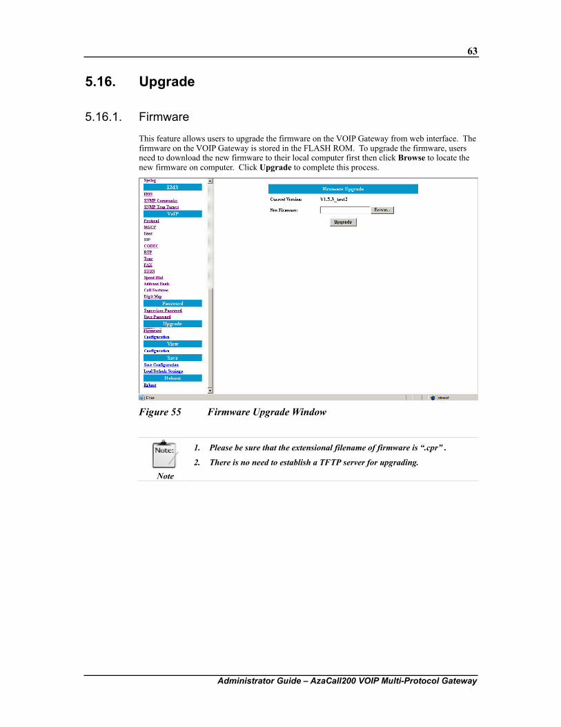
63
Administrator Guide – AzaCall200 VOIP Multi-Protocol Gateway
5.16. Upgrade
5.16.1. Firmware
This feature allows users to upgrade the firmware on the VOIP Gateway from web interface. The firmware on the VOIP Gateway is stored in the FLASH ROM. To upgrade the firmware, users need to download the new firmware to their local computer first then click Browse to locate the new firmware on computer. Click Upgrade to complete this process.
Figure 55 Firmware Upgrade Window
Note
1. Please be sure that the extensional filename of firmware is “.cpr” .
2. There is no need to establish a TFTP server for upgrading.
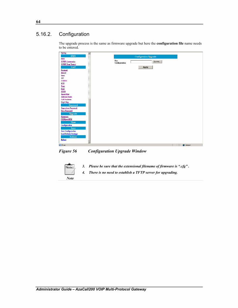
64
Administrator Guide – AzaCall200 VOIP Multi-Protocol Gateway
5.16.2. Configuration
The upgrade process is the same as firmware upgrade but here the configuration file name needs to be entered.
Figure 56 Configuration Upgrade Window
Note
3. Please be sure that the extensional filename of firmware is “.cfg” .
4. There is no need to establish a TFTP server for upgrading.
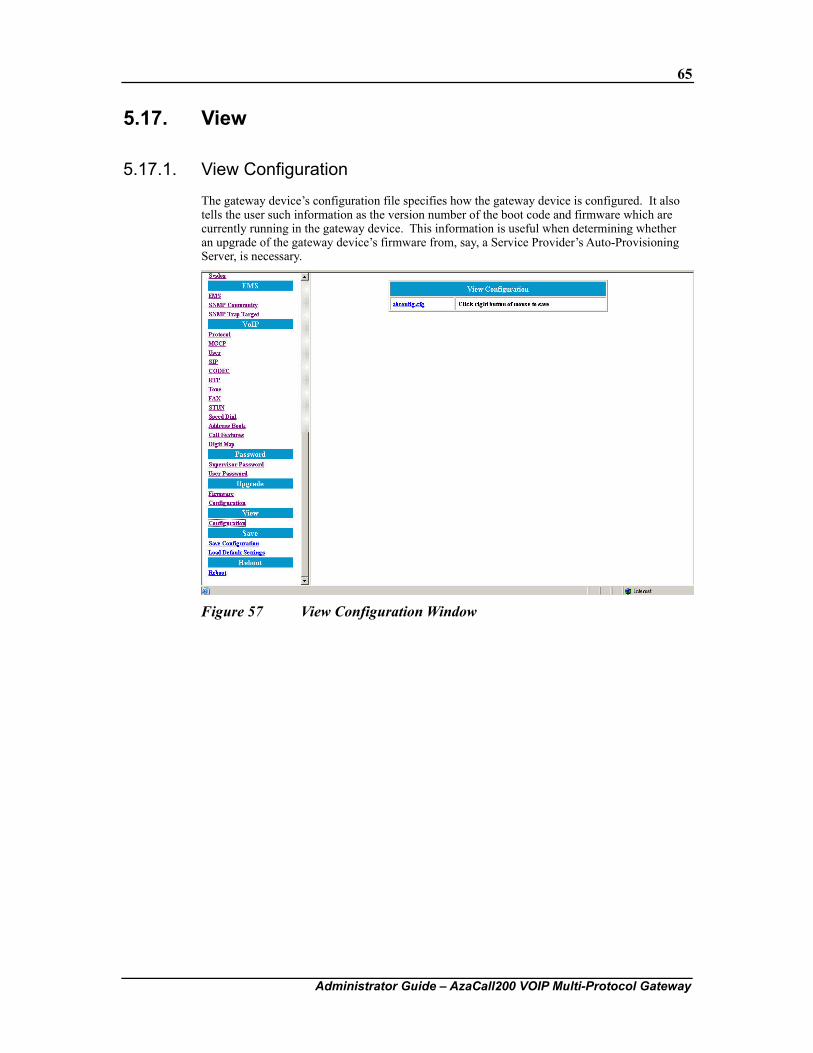
65
Administrator Guide – AzaCall200 VOIP Multi-Protocol Gateway
5.17. View
5.17.1. View Configuration
The gateway device’s configuration file specifies how the gateway device is configured. It also tells the user such information as the version number of the boot code and firmware which are currently running in the gateway device. This information is useful when determining whether an upgrade of the gateway device’s firmware from, say, a Service Provider’s Auto-Provisioning Server, is necessary.
Figure 57 View Configuration Window
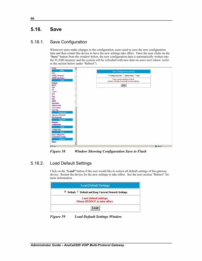
66
Administrator Guide – AzaCall200 VOIP Multi-Protocol Gateway
5.18. Save
5.18.1. Save Configuration
Whenever users make changes to the configuration, users need to save the new configuration data and then restart this device to have the new settings take effect. Once the user clicks on the “Save” button from the window below, the new configuration data is automatically written into the FLASH memory and the system will be refreshed with new data on users next reboot (refer to the section below under “Reboot”).
Figure 58 Window Showing Configuration Save to Flash
5.18.2. Load Default Settings
Click on the “Load” button if the user would like to restore all default settings of the gateway device. Restart the device for the new settings to take effect. See the next section “Reboot” for more information.
Figure 59 Load Default Settings Window
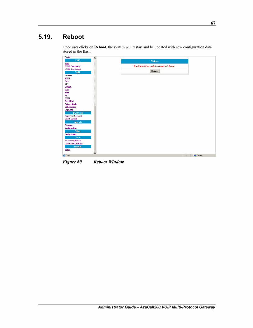
67
Administrator Guide – AzaCall200 VOIP Multi-Protocol Gateway
5.19. Reboot Once user clicks on Reboot, the system will restart and be updated with new configuration data stored in the flash.
Figure 60 Reboot Window
68
Administrator Guide – AzaCall200 VOIP Multi-Protocol Gateway
Chapter 6. Configuration Using Command Line Interface
This chapter explains how to configure and manage the Azatel gateway device using the Command Line Interface (CLI). When compared to the Web Interface described in Chapter 4, CLI provides more expert-like commands to help users configure, maintain, and perform other administrative / diagnostic tasks in the system. User may either use console port, which is built-in, or remote telnet to access the Command Line Interface. The command line interface supports the following four types of commands:
Category Command
Administration Exit, Reboot, Save, and Version Configuration DSCP, EMS, LAN, Mode, NAPT, NTP, PPPoE, Provision, Provisioning,
PSTN, QoS, Syslog, VOIP, and WAN. Maintenance Backup, Dload, flashfs, Loaddefault, and Passwd Monitor Debug
6.1. Log into Command Line Interface There are two ways to log into CLI, one is via console port and the other is via telnet, please refer to sections below for details.
6.1.1. Console Port
Please follow the steps below to log into command line interface:
1. Prepare a terminal simulation program on management host. We have chosen Hyper-Terminal in this guide for demonstration purposes.
2. Loosen and remove the screws from the chassis of the gateway device then open the top cover.
3. Follow the figure below and plug in the designated console conversion cable to the appropriate pin connector on the circuit board.
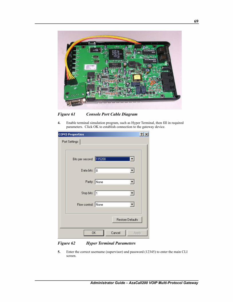
69
Administrator Guide – AzaCall200 VOIP Multi-Protocol Gateway
Figure 61 Console Port Cable Diagram
4. Enable terminal simulation program, such as Hyper Terminal, then fill in required parameters. Click OK to establish connection to the gateway device.
Figure 62 Hyper Terminal Parameters
5. Enter the correct username (supervisor) and password (12345) to enter the main CLI screen.
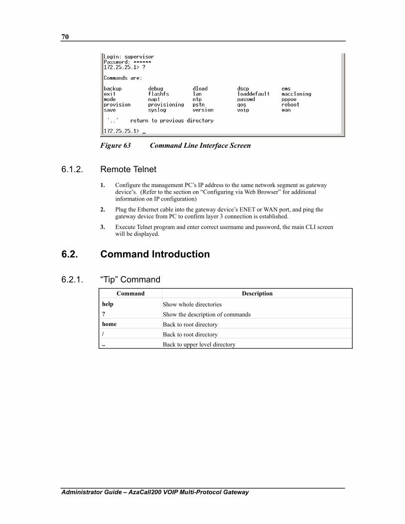
70
Administrator Guide – AzaCall200 VOIP Multi-Protocol Gateway
Figure 63 Command Line Interface Screen
6.1.2. Remote Telnet
1. Configure the management PC’s IP address to the same network segment as gateway device’s. (Refer to the section on “Configuring via Web Browser” for additional information on IP configuration)
2. Plug the Ethernet cable into the gateway device’s ENET or WAN port, and ping the gateway device from PC to confirm layer 3 connection is established.
3. Execute Telnet program and enter correct username and password, the main CLI screen will be displayed.
6.2. Command Introduction
6.2.1. “Tip” Command Command Description
help Show whole directories ? Show the description of commands home Back to root directory / Back to root directory .. Back to upper level directory
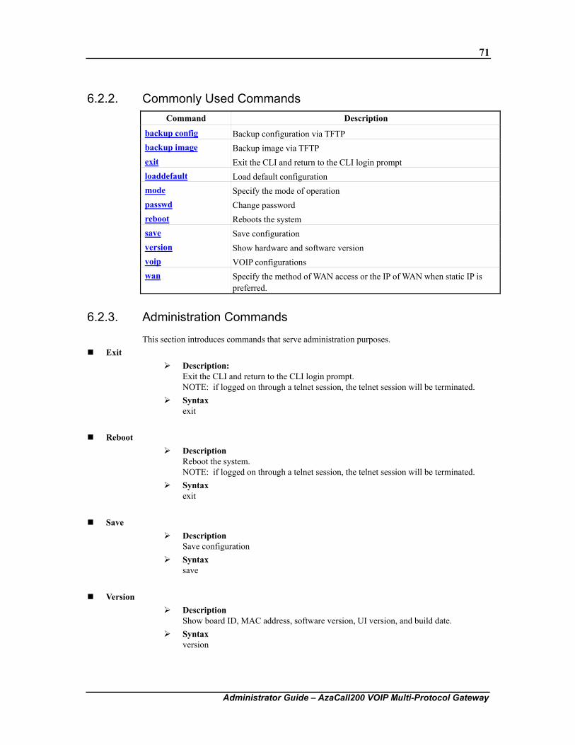
71
Administrator Guide – AzaCall200 VOIP Multi-Protocol Gateway
6.2.2. Commonly Used Commands Command Description
backup config Backup configuration via TFTP backup image Backup image via TFTP exit Exit the CLI and return to the CLI login prompt loaddefault Load default configuration mode Specify the mode of operation passwd Change password reboot Reboots the system save Save configuration version Show hardware and software version voip VOIP configurations wan Specify the method of WAN access or the IP of WAN when static IP is
preferred.
6.2.3. Administration Commands
This section introduces commands that serve administration purposes. Exit
Description: Exit the CLI and return to the CLI login prompt. NOTE: if logged on through a telnet session, the telnet session will be terminated.
Syntax exit
Reboot
Description Reboot the system. NOTE: if logged on through a telnet session, the telnet session will be terminated.
Syntax exit
Save
Description Save configuration
Syntax save
Version
Description Show board ID, MAC address, software version, UI version, and build date.
Syntax version
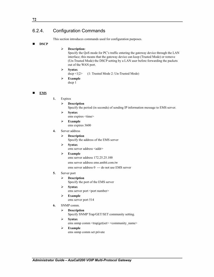
72
Administrator Guide – AzaCall200 VOIP Multi-Protocol Gateway
6.2.4. Configuration Commands
This section introduces commands used for configuration purposes. DSCP
Description: Specify the QoS mode for PC’s traffic entering the gateway device through the LAN interface; this means that the gateway device can keep (Trusted Mode) or remove (Un-Trusted Mode) the DSCP setting by a LAN user before forwarding the packets out of the WAN port.
Syntax dscp <1|2> (1: Trusted Mode 2: Un-Trusted Mode)
Example dscp 1
EMS
1. Expires Description
Specify the period (in seconds) of sending IP information message to EMS server. Syntax
ems expires <time> Example
ems expires 3600
4. Server address Description
Specify the address of the EMS server Syntax
ems server address <addr> Example
ems server address 172.25.25.100 ems server address ems.ambit.com.tw
ems server address 0 --- do not use EMS server
5. Server port Description
Specify the port of the EMS server Syntax
ems server port <port number> Example
ems server port 514
6. SNMP comm. Description
Specify SNMP Trap/GET/SET community setting. Syntax
ems snmp comm <trap|get|set> <community_name> Example
ems snmp comm set private
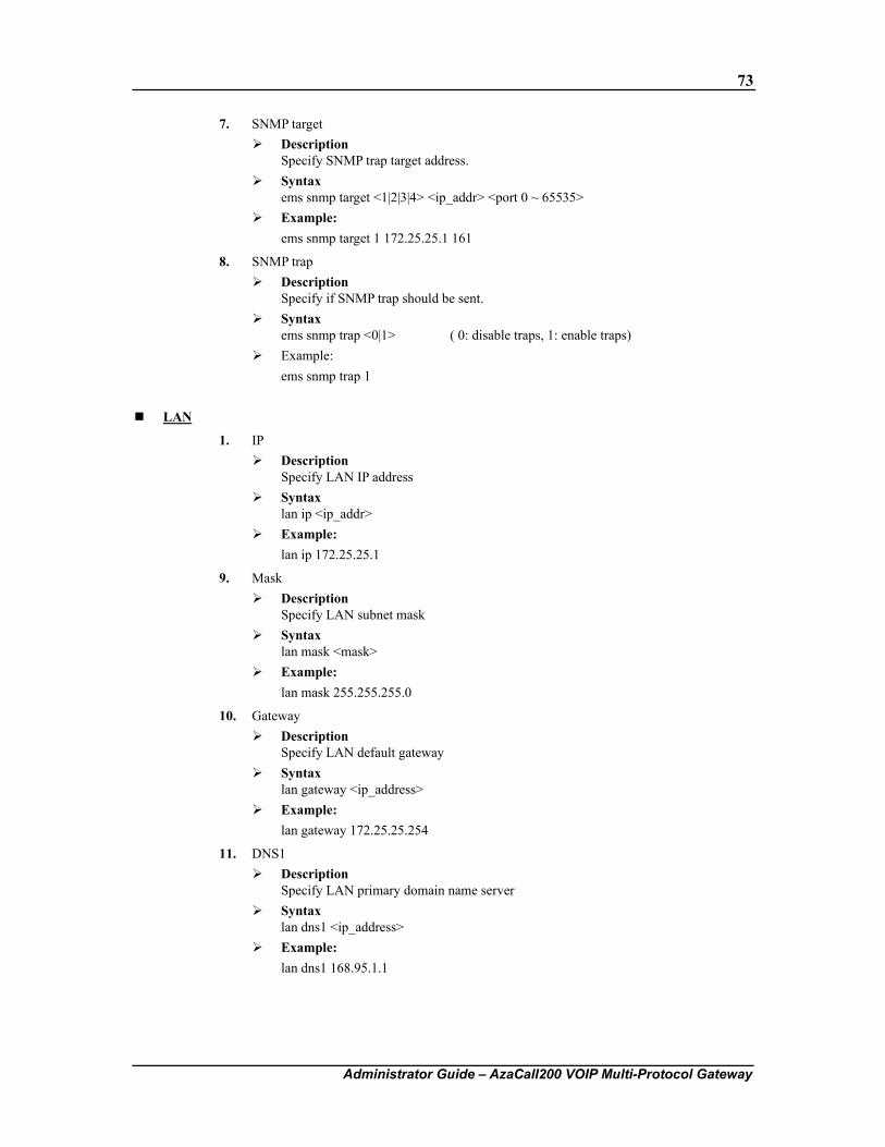
73
Administrator Guide – AzaCall200 VOIP Multi-Protocol Gateway
7. SNMP target Description
Specify SNMP trap target address. Syntax
ems snmp target <1|2|3|4> <ip_addr> <port 0 ~ 65535> Example:
ems snmp target 1 172.25.25.1 161
8. SNMP trap Description
Specify if SNMP trap should be sent. Syntax
ems snmp trap <0|1> ( 0: disable traps, 1: enable traps) Example:
ems snmp trap 1
LAN
1. IP Description
Specify LAN IP address Syntax
lan ip <ip_addr> Example:
lan ip 172.25.25.1
9. Mask Description
Specify LAN subnet mask Syntax
lan mask <mask> Example:
lan mask 255.255.255.0
10. Gateway Description
Specify LAN default gateway Syntax
lan gateway <ip_address> Example:
lan gateway 172.25.25.254
11. DNS1 Description
Specify LAN primary domain name server Syntax
lan dns1 <ip_address> Example:
lan dns1 168.95.1.1
74
Administrator Guide – AzaCall200 VOIP Multi-Protocol Gateway
12. DNS2 Description
Specify LAN secondary domain name server. Syntax
lan dns2 <ip_address> Example:
lan dns2 168.95.192.1
13. DHCP Server mode Description
Set LAN DHCP server to auto or manual mode. Used only when DHCP server is enabled.
Syntax lan dhcpserver mode <auto|manual>
Example: lan dhcpserver mode auto
14. DHCP Server DNS Description
Set the DNS IPs for the LAN DHCP server. Syntax
lan dhcoserver dns <DNS IP 1> [<DNS IP 2> <DNS IP 3>] Example:
lan dhcpserver dns 192.168.1.10 192.168.11.10
15. DHCP Server domain Description
Set the DNS IPs for the LAN DHCP server. Used only when DHCP server is set to "auto" mode.
Syntax lan dhcpserver domain <Domain name> lan dhcpserver domain /clear
Example: lan dhcpserver domain abc.com lan dhcpserver domain /clear
16. DHCP Server enable Description
Enable/disable LAN DHCP server Syntax
lan dhcpserver enable <0|1> (1: Enable, 0: Disable) Example:
lan dhcpserver enable 0
17. DHCP Server lease time Description
Set the default lease time for LAN DHCP server. Used only when DHCP server is set to "auto" mode
Syntax lan dhcpserver leasetime <lease time in seconds>
Example: lan dhcpserver leasetime 86400
75
Administrator Guide – AzaCall200 VOIP Multi-Protocol Gateway
18. DHCP Server pool Description
Set the IP address pool for LAN DHCP server. Used only when DHCP server is set to "auto" mode.
Syntax lan dhcpserver pool <Start IP> <End IP>
Example lan dhcpserver pool 192.168.1.2 192.168.1.10
19. DHCP Server status Description
Show DHCP server status Syntax
lan dhcpserver status Example
lan dhcpserver status Mode
Description: Specify the mode of operation.
Syntax: mode <0|1> ( 0: Bridge Mode, 1: Gateway Mode )
Example mode 0
NAPT
1. Add Description
Add NAPT rule Syntax
napt add basic <publicip> <privateip> napt add filtering <publicip> <privateip> napt add napt <publicip> <privatenetid> <privatemask> napt add port forwarding <forwarding protocol> <forwardip> <forwardport> <serviceip> [serviceport]
Example napt add basic 192.168.100.10 192.168.2.24
napt add filtering 192.168.100.10 192.168.2.24 napt add napt 192.168.100.2 192.168.2.0 255.255.255.0 napt add port forwarding tcp 192.168.2.24 80 192.168.100.50 120
20. Clear Description
Clear NAPT rule Syntax
napt clear <rule> Example
napt clear basic 192.168.100.10 192.168.2.24
76
Administrator Guide – AzaCall200 VOIP Multi-Protocol Gateway
21. DMZ Description
Set the IP address pool for LAN DHCP server. Used only when DHCP server is set to "auto" mode.
Syntax napt dmz <0|1> ( 0: Turn DMZ option off, 1 : Turn DMZ option on) napt dmz <ip_address>
Example napt dmz 192.168.1.2
napt dmz 0
22. Show Description
Show NAPT table Syntax
napt show Example
napt show
NTP
1. Expires Description
Specify the period (in seconds) of retrieving time from NTP server. Syntax
ntp expires <time> Example
ntp expires 86400
2. Server address Description
Specify the address of the ntp server Syntax
ntp server address <addr> Example
ntp address 192.5.41.40 ntp address tick.usno.navy.mil ntp address 0 --- do not use ntp server
3. Sync Description
Synchronize local time with ntp server. Syntax
ntp sync Example
ntp sync
4. Time Zone Description
Specify the time zone. Syntax
ntp timezone <diff_hour> Example
ntp timezone +8
77
Administrator Guide – AzaCall200 VOIP Multi-Protocol Gateway
PPPoE
1. Username Description
pppoe password. Syntax
pppoe username Example
pppoe username
2. Password Description
Specify the password of PPPoE client. Syntax
pppoe password Example
pppoe password
Provision (Central Provisioning)
1. Expires Description
Specify the period (in seconds) of retrieving configuration from provisioning server. Syntax
provision expires <time> Example
provision expires 3600
2. Group Description
Specify the group this device belongs to. Syntax
provision group <group> Example
provision group superuser provision group japan provision group 0 --- this device does not belong to any group
3. Server address Description
Specify the address of the provisioning server. Syntax
provisioning server address <address> Example
provision address 192.168.100.100 provision address provision.ambit.com.tw provision address 0 --- do not use provisioning server
4. Server port Description
Specify the port of the provisioning server. Syntax
provisioning server port <port> Example
provision port 69
78
Administrator Guide – AzaCall200 VOIP Multi-Protocol Gateway
Provisioning (Remote Web Interface Management) Description:
Enable or disable provisioning service from WAN port. Syntax:
provisioning <0|1> (0: Disable, 1: Enable) Example
provisioning 0
PSTN
1. Digit map add Description
Add an entry from the digit map of PSTN redialing. Syntax
pstn digitmap add <prefix> <total_length> Example
pstn digitmap add 1 3 pstn digitmap add 0922 10 pstn digitmap add 002 0 --- total_length = 0 means the length is not fixed, that is,
neither 002x, 002xx, nor 002xxx will perform PSTN redialing.
2. Digit map delete Description
Delete an entry from the digitmap of PSTN redialing. Syntax
pstn digitmap delete <prefix> Example
pstn digitmap delete 0922
3. Digit map show Description
Show the digit map of PSTN redialing. Syntax
pstn digitmap show Example
pstn digitmap show
4. Switch Key Description:
Specify the keys of switching from VOIP mode to PSTN mode. Syntax:
pstn switchkey <keys> Example
pstn switchkey 0000 QoS
1. DSCP Media Get Description
Get media DSCP value Syntax
qos dscp media get Example
qos dscp media get
79
Administrator Guide – AzaCall200 VOIP Multi-Protocol Gateway
2. DSCP Media Set Description
Set media DSCP value Syntax
qos dscp media set <media DSCP number> Example
qos dscp media set 160
3. DSCP Signal Get Description
Get signal DSCP value Syntax
qos dscp signal get Example
qos dscp signal get
4. DSCP Signal Set Description:
Set signal DSCP value Syntax:
qos dscp signal set <signal DSCP number> Example
qos dscp signal set 184
5. Qos Type Get Description
Get QoS type Syntax
qos qostype get Example
qos qostype get
6. QoS Type Set Description
Set Qos type Syntax
qos qostype set <0 (disable) / 1 (DiffServ enable) / 2 (Tos enable)> Example
qos qostype set 1
7. TOS Get Description
Get TOS value Syntax
qos tos get Example
qos tos get
8. TOS Set Description:
Set TOS value Syntax:
qos tos set <tos_number> Example
qos tos set 16
80
Administrator Guide – AzaCall200 VOIP Multi-Protocol Gateway
9. VLAN Tag Add Description
Add VLan tag to ingress frames on port. Syntax
add <port 0(LAN)|1(WAN)> <1(enable)/0(disable)> Example
qos vlantag add 0 1
10. VLAN Tag Set Description
Set vlan tag enable/disable. Syntax
enable <1(enable)/0(disable)> Example
qos vlantag enable 1
11. VLAN Tag Priority Description
Specify 802.1p priority. Syntax
priority <port 0(LAN)|1(WAN)> <priority> Example
qos vlantag priority 0 3
12. VLAN Tag Remove Description
Remove Vlan tag from egress frames on port. Syntax
remove <port 0(LAN)|1(WAN)> <1(enable)/0(disable)> Example
qos vlantag remove 1 1
13. Vlan Tag Replace Description
Replace VLAN tag from ingress frames on port. Syntax
replace <port 0(LAN)|1(WAN)> <1(enable)/0(disable)> Example
qos vlantag replace 0 1
14. VLAN Tag VLAN ID Description
Specify vlan ID. Syntax
vlanid <port 0(LAN)|1(WAN)> <vlanid> Example
qos vlantag vlanid 0 2
81
Administrator Guide – AzaCall200 VOIP Multi-Protocol Gateway
Syslog
1. Server Address Description
Specify the address of the syslog server Syntax
syslog server address <ip_address> Example
syslog server address 192.168.100.100 syslog server address syslog.ambit.com.tw syslog server address 0 --- do not use syslog server
2. Server Port Description:
Specify the port of the syslog server Syntax:
syslog server port <port_number> Example
syslog server port 514
VOIP
1. Call Feature Block Calling ID Enable Description
Set Calling (outgoing) Line ID Blocking Enable/Disable. Syntax
enable <portIndex> <Enable(1)|Disable(0)> Example
callfeature blockclid enable 1 0 callfeature blockclid enable 2 1
2. Call Feature Disconnect Code Description
Set feature code for this item. Syntax
disconnect <code> --- code: <*|#><00~99> Example
voip call feature disconnect code #88
3. Call Feature DND Enable Description
Set DND(Do Not Disturb) Enable/Disable. Syntax
enable <portIndex> <Enable(1)|Disable(0)> Example
voip call feature dnd enable 1 0 voip call feature dnd enable 1 0
4. Call Feature Forward Always Enable Description
Set Call-Forwarding-Always Enable/Disable.
82
Administrator Guide – AzaCall200 VOIP Multi-Protocol Gateway
Syntax voip callfeature forward always enable <portIndex> <Enable (1)|Disable (0)>
Example voip callfeature forwardalways enable 2 1
5. Call Feature Forward Always Number Description
Set Call-Forwarding-Always Forwarding Number. Syntax
voip callfeature forward always number <portIndex> <number> Example
voip callfeature forwardalways number 1 1234 voip callfeature forwardalways number 2 5678
6. Call Feature Forward Busy Enable Description
Set Call-Forwarding-Busy Enable/Disable. Syntax
voip callfeature forward busy enable <portIndex> <Enable(1)|Disable(0)> Example
voip callfeature forwardbusy enable 1 0 voip callfeature forwardbusy enable 2 1
7. Call Feature Forward Busy Number Description
Set Call-Forwarding-Busy Forwarding Number. Syntax
voip callfeature forwardbusy number <portIndex> <number> Example
voip callfeature forwardbusy number 1 1234 voip callfeature forwardbusy number 2 5678
8. Call Feature Forward No Answer Enable Description
Set Call-Forwarding No-Answer Enable/Disable. Syntax
voip callfeature forwardnoans enable <portIndex> <Enable(1)|Disable(0)> Example
voip callfeature forwardnoans enable 1 0
9. Call Feature Forward No Answer Number Description
Set Call-Forwarding No-Answer Forwarding Number. Syntax
voip callfeature forwardnoans number <portIndex> <number> Example
voip callfeature forwardnoans number 1 1234 voip callfeature forwardnoans number 2 5678
83
Administrator Guide – AzaCall200 VOIP Multi-Protocol Gateway
10. Call feature Forward No Answer Ring Number Description
Set Call-Forwarding-No Answer Forwarding number of notification rings. Syntax
voip callfeature forwardnoans ringnumber <portIndex> <number> Example
voip callfeature forwardnoans ringnumber 1 3 voip callfeature forwardnoans ringnumber 2 6
11. Call feature Hold Enable Description
Set Call Hold Enable/Disable. Syntax
enable <portIndex> <Enable(1)|Disable(0)> Example
voip callfeature hold enable 1 0 voip callfeature hold enable 2 1
12. Call feature Reject Private (Anonymous Call) Enable Description
Set Anonymous Call (incoming) Rejection Enable/Disable. Syntax
enable <portIndex> <Enable(1)|Disable(0)> Example
voip callfeature rejprivate enable 1 0 voip callfeature rejprivate enable 2 1
13. Call feature Transfer transfer_code / with_code / without_code Description
Set feature code for this item. Syntax
<command> <portIndex> <code> --- code: <*|#><00~99> Example
voip callfeature transfer transfer_code #88 voip callfeature transfer with_code #88 voip callfeature transfer without_code #88
14. Call feature Transfer with Consultation Description
Set Call Transfer With Consultation Enable/Disable. Syntax
enable <portIndex> <Enable(1)|Disable(0)> Example
voip callfeature transfer with_en enable 1 0
15. Call feature Transfer without Consultation Description
Set Call Transfer Without Consultation Enable/Disable. Syntax
84
Administrator Guide – AzaCall200 VOIP Multi-Protocol Gateway
mode <portIndex> <type> --- type: 0: Disable, 1: Enable Example
voip callfeature transfer without_en enable 2 1
16. Call feature Waiting Enable Description
Set Call Waiting Enable/Disable. Syntax
enable <portIndex> <Enable(1)|Disable(0)> Example
voip callfeature waiting enable 1 0 voip callfeature waiting enable 2 1
17. Call History Show Description
Show current call history records. Syntax
show Example
voip callhistory show
18. Codec Prefer Description
Specify the preferred codec Syntax
prefer <codec_type> -- (0: PCMU(G.711 u-law), 1: PCMA(G.711 A-law), 2: G.729A, 3: G.723.1)
Example voip codec prefer 0
19. Codec Rate Description
Specify the preferred codec rate in milliseconds. (10/20/30) Syntax
codec rate <rate> -- (rate: 10/20/30) Example
voip codec rate 20
20. Codec VAD Description
Enable voice activity detection (VAD) Syntax
vad <0: Disable|1:Enable> Example
voip codec vad 0
21. Digit map reset Description
Reset the digit map of VOIP.
85
Administrator Guide – AzaCall200 VOIP Multi-Protocol Gateway
Syntax reset
Example voip digitmap reset
22. Digit map set Description
Set the Digitmap of VOIP. Prefix Max Length: 15 Syntax
set <digitmap1>|<digitmap2>|...|<digitmap10> Example
set 0910xxxxx set 0910xxxxx|09[0-9]xxxx set 0910xxxxx|09[0-9]xxxx|09[0-9][09]xxxx
23. Digit map show Description
Show the digit map of VOIP Syntax
show Example
voip digitmap show
24. Endpoint busy tone Description
Set busy tone pattern Syntax
Scenario 1 busytone <ontime,offtime,freq1,freq2> -- (on-time : tone on time (ms), off-time: tone off time (ms), freq1 : frequency 1 (Hz), freq2 : frequency 2 (Hz)) Scenario 2 busytone <ontime1,offtime1,ontime2,offtime2,freq1,freq2> --- (ontime1 : tone on time1 (ms), offtime1: tone off time1 (ms), ontime2 : tone on time2 (ms), offtime2: tone off time2 (ms), freq1 : frequency 1 (Hz), freq2 : frequency 2 (Hz))
Example voip endpoint busytone 500,500,480,620
voip endpoint busytone 500,500,500,100,480,620
25. Endpoint call wait tone Description
Set call waiting tone pattern. Syntax
Scenario 1 callwaittone <ontime,offtime,freq1,freq2>
--- on-time : tone on time(ms) off-time: tone off time(ms) freq1 : frequency 1 (Hz)
86
Administrator Guide – AzaCall200 VOIP Multi-Protocol Gateway
freq2 : frequency 2 (Hz) Scenario 2 callwaittone <ontime1,offtime1,ontime2,offtime2,freq1,freq2> --- on-time1 : tone on time1(ms) off-time1: tone off time1(ms) on-time2 : tone on time2(ms) off-time2: tone off time2(ms) freq1 : frequency 1 (Hz) freq2 : frequency 2 (Hz) Scenario 3 callwaittone <ontime1,offtime1,ontime2,offtime2,ontime3,offtime3,freq1,freq2 --- on-time1 : tone on time1(ms) off-time1: tone off time1(ms) on-time2 : tone on time2(ms)
off-time2: tone off time2(ms) on-time3 : tone on time3(ms) off-time3: tone off time3(ms) freq1 : frequency 1 (Hz) freq2 : frequency 2 (Hz)
Example voip endpoint callwaittone 500,500,440,0
voip endpoint callwaittone 250,250,250,5250,350,440 voip endpoint callwaittone 100,100,250,250,250,5250,350,440
26. Endpoint dial tone Description
Set dial tone pattern Syntax
dialtone <ontime,offtime,freq1,freq2> Example
voip endpoint dialtone 1000,0,350,440
27. Endpoint ring Description
Set ring cadence Syntax
ring <ontime,offtime> ( ontime : ring on time (ms), offtime: ring off time (ms) ) Example
voip endpoint ring 2000,4000
28. Endpoint ring back tone Description
Set ring back tone pattern Syntax
ringbakctone <ontime,offtime,freq1,freq2> ringbacktone <ontime1,offtime1,ontime2,offtime2,freq1,freq2>
Example
87
Administrator Guide – AzaCall200 VOIP Multi-Protocol Gateway
voip endpoint ringbakctone 2000,4000,440,480 voip endpoint ringbakctone 400,200,400,3000,440,480
29. Endpoint rx gain (Receive Gain) Description
Set receive audio gain in dB Syntax
rxgain <dB> ; ( dB: -36 ~ +18 ) Example
voip endpoint rxgain 0 voip endpoint rxgain +3 voip endpoint rxgain –3
30. Endpoint tx gain (Transmit Gain ) Description
Set transmit audio gain in dB Syntax
txgain <dB> ( dB: -36 ~ +18 ) Example
voip endpoint txgain 0 voip endpoint txgain +3 voip endpoint txgain –3
31. Fax T38 Description
Enable T.38 fax Syntax
voip fax t38 <0:Disable|1:Enable> Example
voip fax t38 1
32. Fax T38 port Description
Specify the port number to send/receive T.38 packets Syntax
fax t38port <port> (port x : used by 1st T.38 session; port x + 2: used by 2nd T.38 session) Example
voip fax t38port 49170 --- 1st T.38 session uses port 49170, 2nd T.38 session uses port 49172
33. MGCP call agent address Description
Specify the address of callagent. Syntax
address <addr> Example
voip mgcp callagent address 195.37.77.101 voip mgcp callagent address ca.mgcp.com
88
Administrator Guide – AzaCall200 VOIP Multi-Protocol Gateway
34. MGCP call agent port Description
Specify the port of callagent. Syntax
port <port> Example
voip mgcp callagent port 2727
35. MGCP endpoint ID style Description
Specify endpoint id style. Syntax
epidstyle <0|1|2> --- 0: aaln/#@[ip_addr] 1: mac_addr/#@[ip_addr] 2: aaln/#@mac_addr
Example voip mgcp epidstyle 0
36. MGCP expires Description
Specify the period(in seconds) of sending keep alive message to callagent. Syntax
expires 60 Example
voip mgcp expires 60
37. MGCP local port Description
Specify the local listening port of MGCP stack. Syntax
localport <port> Example
voip mgcp localport 2427
38. MGCP send RSIP Description
Enable sending RSIP with wildcarded endpoint id. Syntax
wildrsip <0|1> --- 0: disable 1: enable
Example voip mgcp wildrsip 0
39. Protocol Description
Specify VoIP signaling protocol. Syntax
protocol <0|1|2> --- 0: MGCP
89
Administrator Guide – AzaCall200 VOIP Multi-Protocol Gateway
1: SIP Example
voip protocol 1
40. RTP port Description
Specify the port number to send/receive RTP packets Syntax
port <port> (port x : used by 1st T.38 session; port x + 2: used by 2nd T.38 session) Example
voip rtp port 49170 --- 1st T.38 session uses port 49170, 2nd T.38 session uses port 49172
41. Service disable Description
Disable service with line ID. Syntax
disable <line ID> Example
voip service disable 1
42. Service enable Description
Enable service with line ID. Syntax
enable <line ID> Example
voip sip enable 1
43. Service show Description
Show the service of line. Syntax
show Example
voip service show
44. Service enable Description
Enable service with line ID. Syntax
enable <line ID> Example
voip sip enable 1
45. SIP domain Description
Specify the domain name for the URI to be registered. For example, if the settings are,
username : 1234, domain : iptel.org, registrar: 195.37.77.101
90
Administrator Guide – AzaCall200 VOIP Multi-Protocol Gateway
then the URI sip of [email protected] will be registered in 195.37.77.101. Syntax
domain <addr> domain 0 --- use local ip address as domain name
Example voip sip domain iptel.org voip sip domain 195.37.77.101
voip sip domain 0
46. SIP Expires Description
Specify the period(in seconds) that the sip registration will expire Syntax
voip sip expires <time> Example
voip sip expires 3600
47. SIP Localport Description
Specify the local listening port of SIP stack Syntax
voip sip localport <port number> Example
voip sip localport 5060
48. SIP Outbound Address Description
Specify the address of sip outbound proxy. Syntax
outbound <addr> Example
voip sip outbound 195.37.77.101 voip sip outbound outbound.sip.com
voip sip outbound 0 --- do not use outbound proxy
49. SIP Outbound Port Description
Specify the port of sip outbound proxy. Syntax
port <port> Example
voip sip outbound port 5065
50. SIP Proxy address Description
Specify the address of sip proxy Syntax
voip sip proxy address <ip_address> Example
91
Administrator Guide – AzaCall200 VOIP Multi-Protocol Gateway
voip sip proxy address 195.37.77.101 voip sip proxy address proxy.sip.com voip sip proxy address 0 --- do not use proxy
51. SIP Proxy port Description
Specify the port of sip proxy Syntax
voip sip proxy port <port number> Example
voip sip proxy port 5060
52. SIP Registrar address Description
Specify the address of sip registrar Syntax
voip sip registrar address <ip_address> Example
voip sip registrar address 195.37.77.101 voip sip registrar address registrar.sip.com voip sip registrar address 0 --- do not use registrar
53. SIP Registrar port Description
Specify the port of sip registrar Syntax
voip sip registrar port <port_number> Example
voip sip registrar port 5060
54. SIP Subject Description
Specify the content of the subject header in outgoing INVITE message. This is used to indicate the title of the call.
Syntax voip sip subject <text>
Example voip sip subject Azatel
55. Speed dial add Description
Add an entry into the speed dial table. Syntax
voip speeddial add <number> <destination> Example
voip speeddial add 111 [email protected] voip speeddial add 222 [email protected]:5061 voip speeddial add 333 [email protected]
92
Administrator Guide – AzaCall200 VOIP Multi-Protocol Gateway
56. Speed dial delete Description
Delete an entry in the speed dial table. Syntax
voip speeddial delete <number> Example
voip speeddial delete 111
57. Speed dial show Description
Show speed dial table Syntax
voip speeddial show Example
voip speeddial show
58. STUN Expires Description
Specify the period (in seconds) of sending STUN message to STUN server. Syntax
voip stun expires <time_in_seconds> Example
voip stun expires 60
59. STUN local port Description
Specify the local listening port of STUN client. Syntax
voip stun localport <port_number> Example
voip stun localport 3478
60. STUN NAT address Description
Specify the IP address of the NAT firewall. Should be specified if this device is located behind an NAT firewall. The NAT firewall should also activate port mapping or DMZ functions to forward incoming VOIP signaling packet and RTP packets to this device. Make sure the STUN (Simple Traversal of User Datagram) server address is 0 if user wants to specify NAT address by himself. If the IP address of the NAT firewall is unknown, specify STUN server to determine it automatically.
Syntax voip stun nataddress <ip_address>
Example voip stun nataddress 211.23.52.163 voip stun nataddress 0
61. STUN Server address Description
Specify the address of STUN (Simple Traversal of User Datagram) server. It is used
93
Administrator Guide – AzaCall200 VOIP Multi-Protocol Gateway
to detect the IP address of the NAT firewall. If this function is enabled, after detecting the IP address of the NAT firewall, "nataddress" will be changed automatically.
Syntax voip stun server address <ip_address>
Example voip stun server address 66.7.238.213 voip stun server address larry.gloo.net voip stun server address 0 --- do not use STUN server
62. STUN Server port Description
Specify the port of STUN server. Syntax
voip stun server port <port number> Example
voip stun server port 3478
63. User user<0|1> display name Description
Specify the display name of user 0. Syntax
voip user user0 displayname Example
voip user user0 displayname
64. User user<0|1> password Description
Specify the password of user 0. Syntax
voip user user0 password Example
voip user user0 password
65. User user<0|1> user name Description
Specify the user name of user 0. Syntax
voip user user0 username Example
voip user user0 username
WAN Description
Specify the method of WAN access or the IP of WAN when static IP is preferred. Syntax
wan <0|1|2> ( 0:Static IP, 1: DHCP client, 2: PPPoE client ) wan <address> <mask> <default gateway>
Example wan 1 wan 192.168.1.1 255.255.255.0 192.168.1.254
94
Administrator Guide – AzaCall200 VOIP Multi-Protocol Gateway
6.2.5. Maintenance Commands
This section introduces commands used for maintenance purpose. Backup
1. Configuration Description
Backup configuration via TFTP. The host should run TFTP server application first. Syntax
backup config <TFTP IP address> Example
backup config 192.168.100.100
23. Image Description
Backup image via TFTP. The host should run TFTP server application first. Syntax
backup image <TFTP IP address> Example
backup image 192.168.100.100
Dload Description
Download image via TFTP. The host should run TFTP server first. Syntax
dload <TFTP IP address > <file> Example
dload 192.168.100.100 ram.cpr Flashfs
1. Copy Description
Copy files from source device to destination device. Syntax
flashfs copy <srcDev/file> <dstDev/file> Example
flashfs copy 192.168.100.100/appmgcp.bin.gz app1 flashfs copy cli/abconfig.cfg ram flashfs copy cli/abconfig.cfg 192.168.100.100
2. Dir Description
Display files in <dev> Syntax
flashfs dir <dev> Example
flashfs dir . flashfs dir app1
3. Format Description
Format or erase <dev> Syntax
flashfs format <dev> Example
95
Administrator Guide – AzaCall200 VOIP Multi-Protocol Gateway
flashfs format app1
4. Reboot Description
Reboot system Syntax
flashfs reboot Example
flashfs reboot
Load Default Description
Load default configuration. Syntax
loaddefault Example
loaddefault
Password Description
Change password. Syntax
passwd Example
passwd
MacCloning
1. Enable Description
Enable or disable mac cloning. Syntax
enable <0|1> --- 0: disable mac cloning 1: enable mac cloning
Example maccloning enable 0
24. MAC Description
Specify the mac address for mac cloning. Syntax
mac <mac address> Example
macclong mac 00028A59FF27
6.2.6. Diagnostic Commands
This section introduces commands which serve diagnostic purposes. Debug
2. Config Active Delete / Get / Set / Show Description
Delete / get / set /show ACTIVE configuration.
96
Administrator Guide – AzaCall200 VOIP Multi-Protocol Gateway
Syntax config active delete <name> config active get <name> config active set <name> <value> config active show
Example debug config active delete ntp_server_address debug config active get ntp_server_address debug config active set ntp_server_address 192.168.100.100 debug config active show
25. Config Flash Delete / Get / Set / Show Description
Delete / get / set /show FLASH configuration Syntax
config flash delete <name> config flash get <name> config flash set <name> <value> config flash show
Example debug config flash delete ntp_server_address debug config flash get ntp_server_address debug config flash set ntp_server_address 192.168.100.100 debug config flash show
26. DHCPC Renew Description
Show DHCP client status Syntax
debug dhcpc renew Example
debug dhcpc renew
27. DHCP Server Description
Show DHCP server status Syntax
debug dhcpc server Example
debug dhcpc server
28. DHCPC Show Description
Show DHCP client status Syntax
debug dhcpc show Example
debug dhcpc show
29. Level Description
Set debug level Syntax
debug level <0|1|2|3|4> ( 0: do not show debug messages 1: show ERROR2: show ERROR and WARNING 3: show ERROR ,WARNING and INFO
97
Administrator Guide – AzaCall200 VOIP Multi-Protocol Gateway
4: show ERROR ,WARNING, INFO and DEBUG ) Example
debug level 0
30. Ping Description
Ping remote host Syntax
debug ping <ip_address> Example
debug ping 192.168.100.100
31. PPPoE Description
Show PPPoE client status Syntax
debug pppoe Example
debug pppoe
32. PSTN Redial Control Description
Control PSTN redial Task to be Enable/Disable Syntax
debug pstn redial control <0: disabled | 1:enabled> Example
debug pstn redial control 0
33. PSTN Relay Control Description
Control automatic relay switch to be Enable/Disable Syntax
debug pstn relay control <0: disabled | 1:enabled > Example
debug pstn relay control 0
34. PSTN Relay State Get / Set Description
Get relay switch state and set relay switch state for specific channel. Syntax
debug pstn relay state get <1|2> ( 1: channel 1 relay state, 2: channel 2 relay state ) debug pstn relay state set <L1|L2> <0|1> ( 0: PSTN route, 1: VOIP route )
Example debug pstn relay state get 1 debug pstn relay state set L1 0
35. PSTN Show Digitmap Description
Show digit map of PSTN library. Syntax
debug pstn show digitmap Example
debug pstn show digitmap
36. PSTN Show Switchkey Description
Show switch key of PSTN library
98
Administrator Guide – AzaCall200 VOIP Multi-Protocol Gateway
Syntax debug pstn show switchkey
Example debug pstn show switchkey
37. PSTN Version Description
Show PSTN Library version Syntax
debug pstn version Example
debug pstn version
38. Showlog Description
Show historical log Syntax
showlog console ( show historical log in console) showlog tftp <Addr> ( tftp transfer historical log to server (filename: log.txt) ) showlog tftp <Addr> <FileName> ( tftp transfer historical log to server with a specified file name )
Example debug showlog console debug showlog tftp 211.23.52.163 debug showlog tftp tftp.ambit.com.tw debug showlog tftp 211.23.52.163 20030523.log
39. Showmsg Description
Redirect standard input/output/error to current task. Syntax
showmsg Example
debug showmsg
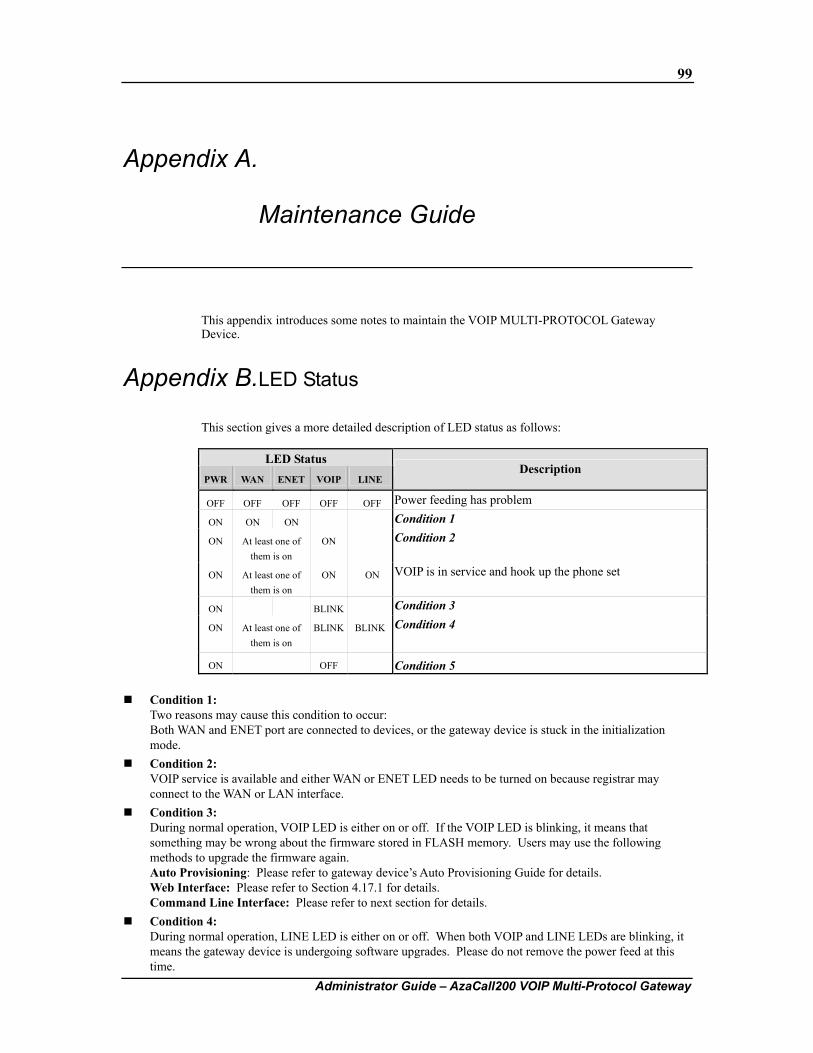
99
Administrator Guide – AzaCall200 VOIP Multi-Protocol Gateway
Appendix A. Maintenance Guide
This appendix introduces some notes to maintain the VOIP MULTI-PROTOCOL Gateway Device.
Appendix B. LED Status
This section gives a more detailed description of LED status as follows:
LED Status PWR WAN ENET VOIP LINE
Description
OFF OFF OFF OFF OFF Power feeding has problem
ON ON ON Condition 1
ON At least one of them is on
ON Condition 2
ON At least one of them is on
ON ON VOIP is in service and hook up the phone set
ON BLINK Condition 3
ON At least one of them is on
BLINK BLINK
Condition 4
ON OFF Condition 5
Condition 1: Two reasons may cause this condition to occur: Both WAN and ENET port are connected to devices, or the gateway device is stuck in the initialization mode.
Condition 2: VOIP service is available and either WAN or ENET LED needs to be turned on because registrar may connect to the WAN or LAN interface.
Condition 3: During normal operation, VOIP LED is either on or off. If the VOIP LED is blinking, it means that something may be wrong about the firmware stored in FLASH memory. Users may use the following methods to upgrade the firmware again. Auto Provisioning: Please refer to gateway device’s Auto Provisioning Guide for details. Web Interface: Please refer to Section 4.17.1 for details. Command Line Interface: Please refer to next section for details.
Condition 4: During normal operation, LINE LED is either on or off. When both VOIP and LINE LEDs are blinking, it means the gateway device is undergoing software upgrades. Please do not remove the power feed at this time.
100
Administrator Guide – AzaCall200 VOIP Multi-Protocol Gateway
Condition 5: It means that gateway device is out of service or boot code is not functioning properly.
Appendix C. Software Description
The different software associated with the gateway device can be classified into 3 types: boot code, firmware, and configuration.
Boot code: Stored in the device’s FLASH memory and is necessary to boot up a system. - The gateway device allows administrators to upgrade the boot code when necessary. - Please note that if boot code becomes corrupt while upgrading, do not reboot the device with the corrupt boot code and immediately run the upgrade commands to perform the upgrade again. Rebooting the device with corrupt boot code may cause the gateway device to become unstable and experience a system-hang condition. - To recover from such hang condition, copy the entire software (boot code + firmware) into the gateway device’s Flash memory using a FLASH Programmer rather than via TFTP. It may be necessary to remove the Flash memory chip from the PCB for this procedure. - For additional upgrade procedures, please refer to section A.2.2.
Firmware (AP): Stored in the device’s FLASH memory and is necessary to provide VOIP service. There are 3 ways to upgrade the firmware for the gateway device. Generally speaking, the Auto Provisioning function can download the latest firmware from the provisioning server automatically; users however, may upgrade the firmware themselves via the web interface. If upgrade fails and the firmware becomes corrupt, the administrator can also log into maintenance mode to recover the device via remote telnet or console port. For additional upgrade procedures, please refer to section A.2.2.
Configuration: Stored in the FLASH or RAM, depending on whether configurations have been saved into FLASH or not. The gateway device’s configuration file can be upgraded using the same 3 approaches as the firmware. If the users do not specify any configurations, the system will create a default configuration as long as the firmware is working. For additional upgrade procedures, please refer to section A.2.2.
In addition to the types of software codes described above, another item worth mentioning is the “Board ID”. When a user or administrator upgrades firmware using any of the approaches described above, the firmware version used will depend on a “compatible list” which specifies if the firmware version is suitable given the BoardID residing in the gateway device.
Appendix D. Recovery Procedure
The following recovery procedures may apply when neither auto provisioning nor web interface is working, and the boot code has a version number of V1.6.5j or later.
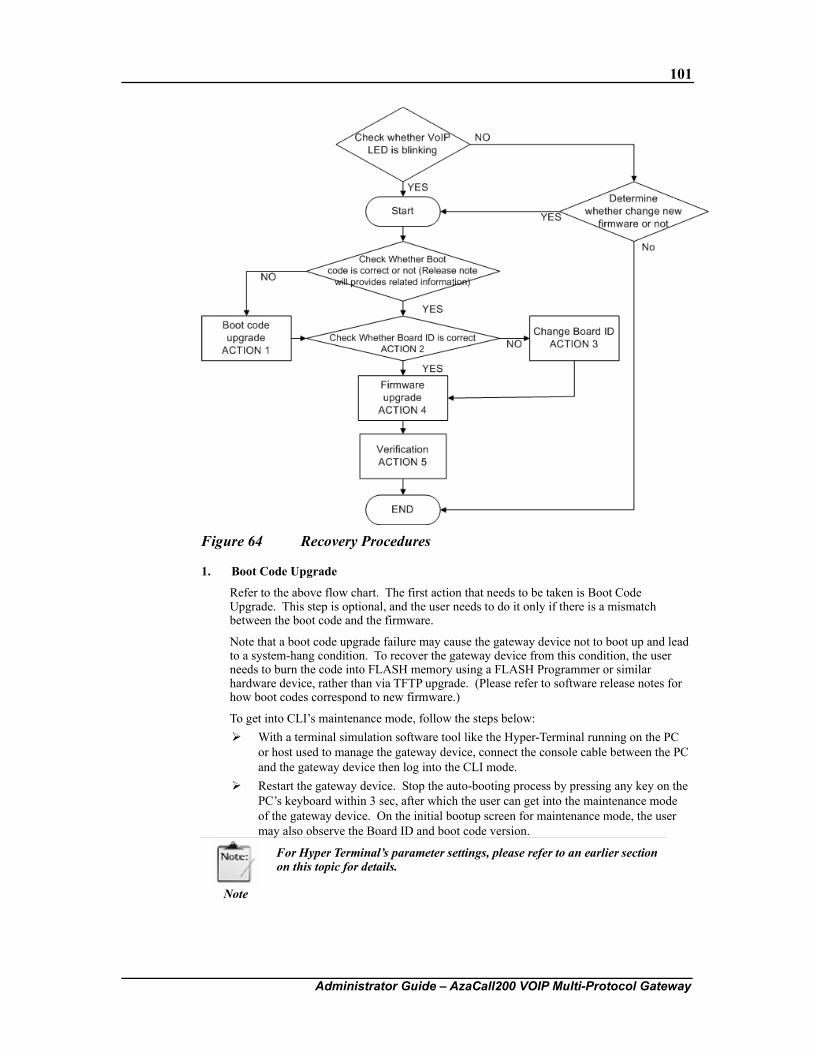
101
Administrator Guide – AzaCall200 VOIP Multi-Protocol Gateway
Figure 64 Recovery Procedures
1. Boot Code Upgrade
Refer to the above flow chart. The first action that needs to be taken is Boot Code Upgrade. This step is optional, and the user needs to do it only if there is a mismatch between the boot code and the firmware.
Note that a boot code upgrade failure may cause the gateway device not to boot up and lead to a system-hang condition. To recover the gateway device from this condition, the user needs to burn the code into FLASH memory using a FLASH Programmer or similar hardware device, rather than via TFTP upgrade. (Please refer to software release notes for how boot codes correspond to new firmware.)
To get into CLI’s maintenance mode, follow the steps below: With a terminal simulation software tool like the Hyper-Terminal running on the PC
or host used to manage the gateway device, connect the console cable between the PC and the gateway device then log into the CLI mode.
Restart the gateway device. Stop the auto-booting process by pressing any key on the PC’s keyboard within 3 sec, after which the user can get into the maintenance mode of the gateway device. On the initial bootup screen for maintenance mode, the user may also observe the Board ID and boot code version.
Note
For Hyper Terminal’s parameter settings, please refer to an earlier section on this topic for details.
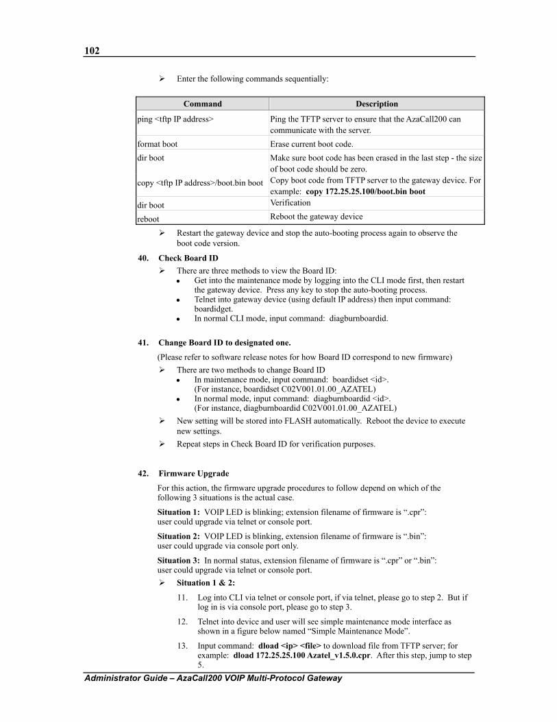
102
Administrator Guide – AzaCall200 VOIP Multi-Protocol Gateway
Enter the following commands sequentially:
Command Description
ping <tftp IP address> Ping the TFTP server to ensure that the AzaCall200 can communicate with the server.
format boot Erase current boot code. dir boot Make sure boot code has been erased in the last step - the size
of boot code should be zero. copy <tftp IP address>/boot.bin boot Copy boot code from TFTP server to the gateway device. For
example: copy 172.25.25.100/boot.bin boot dir boot Verification
reboot Reboot the gateway device
Restart the gateway device and stop the auto-booting process again to observe the boot code version.
40. Check Board ID There are three methods to view the Board ID:
Get into the maintenance mode by logging into the CLI mode first, then restart the gateway device. Press any key to stop the auto-booting process.
Telnet into gateway device (using default IP address) then input command: boardidget.
In normal CLI mode, input command: diagburnboardid.
41. Change Board ID to designated one.
(Please refer to software release notes for how Board ID correspond to new firmware) There are two methods to change Board ID
In maintenance mode, input command: boardidset <id>. (For instance, boardidset C02V001.01.00_AZATEL)
In normal mode, input command: diagburnboardid <id>. (For instance, diagburnboardid C02V001.01.00_AZATEL)
New setting will be stored into FLASH automatically. Reboot the device to execute new settings.
Repeat steps in Check Board ID for verification purposes.
42. Firmware Upgrade
For this action, the firmware upgrade procedures to follow depend on which of the following 3 situations is the actual case.
Situation 1: VOIP LED is blinking; extension filename of firmware is “.cpr”: user could upgrade via telnet or console port.
Situation 2: VOIP LED is blinking, extension filename of firmware is “.bin”: user could upgrade via console port only.
Situation 3: In normal status, extension filename of firmware is “.cpr” or “.bin”: user could upgrade via telnet or console port.
Situation 1 & 2:
11. Log into CLI via telnet or console port, if via telnet, please go to step 2. But if log in is via console port, please go to step 3.
12. Telnet into device and user will see simple maintenance mode interface as shown in a figure below named “Simple Maintenance Mode”.
13. Input command: dload <ip> <file> to download file from TFTP server; for example: dload 172.25.25.100 Azatel_v1.5.0.cpr. After this step, jump to step 5.
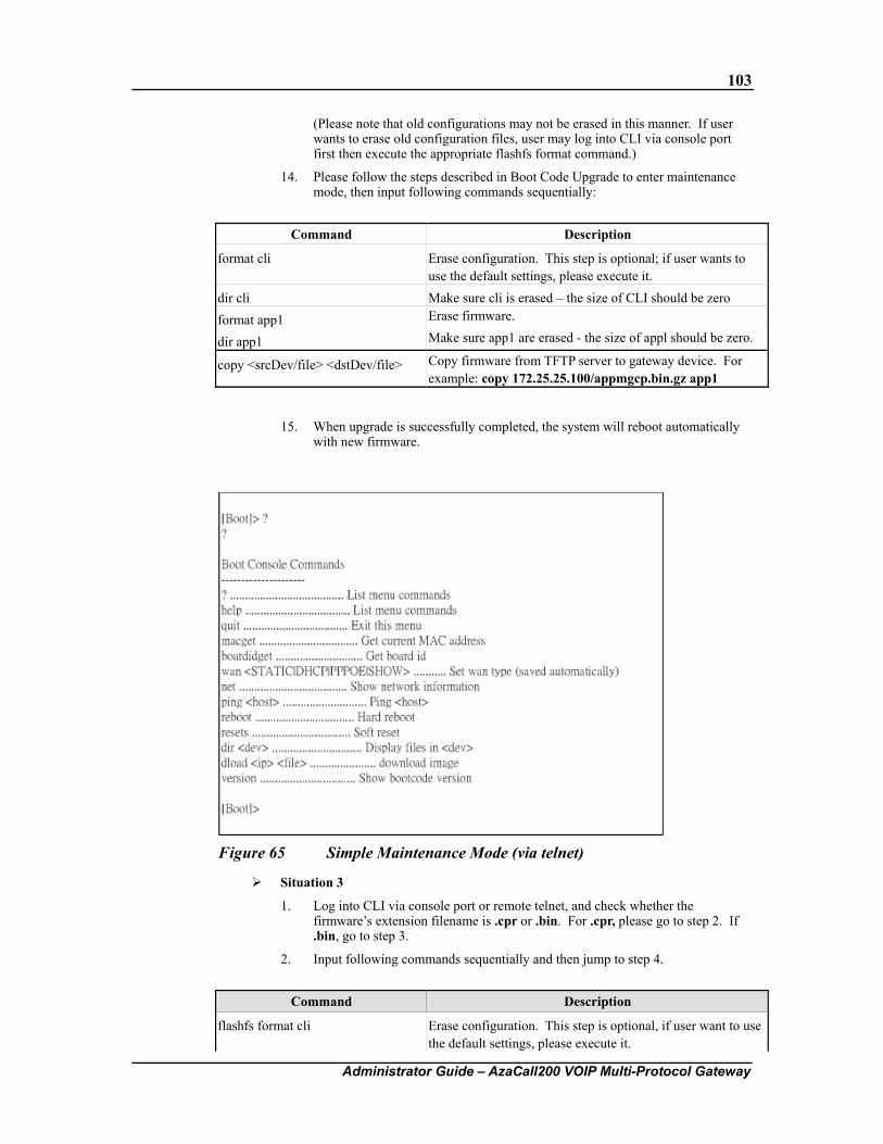
103
Administrator Guide – AzaCall200 VOIP Multi-Protocol Gateway
(Please note that old configurations may not be erased in this manner. If user wants to erase old configuration files, user may log into CLI via console port first then execute the appropriate flashfs format command.)
14. Please follow the steps described in Boot Code Upgrade to enter maintenance mode, then input following commands sequentially:
Command Description
format cli Erase configuration. This step is optional; if user wants to use the default settings, please execute it.
dir cli Make sure cli is erased – the size of CLI should be zero format app1 Erase firmware.
dir app1 Make sure app1 are erased - the size of appl should be zero.
copy <srcDev/file> <dstDev/file> Copy firmware from TFTP server to gateway device. For example: copy 172.25.25.100/appmgcp.bin.gz app1
15. When upgrade is successfully completed, the system will reboot automatically with new firmware.
Figure 65 Simple Maintenance Mode (via telnet)
Situation 3
1. Log into CLI via console port or remote telnet, and check whether the firmware’s extension filename is .cpr or .bin. For .cpr, please go to step 2. If .bin, go to step 3.
2. Input following commands sequentially and then jump to step 4.
Command Description
flashfs format cli Erase configuration. This step is optional, if user want to use the default settings, please execute it.
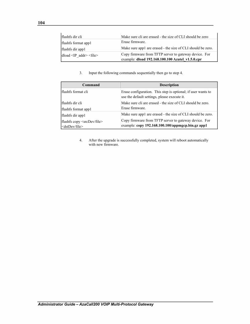
104
Administrator Guide – AzaCall200 VOIP Multi-Protocol Gateway
flashfs dir cli Make sure cli are erased - the size of CLI should be zero flashfs format app1 Erase firmware.
flashfs dir app1 Make sure app1 are erased - the size of CLI should be zero.
dload <IP_addr> <file> Copy firmware from TFTP server to gateway device. For example: dload 192.168.100.100 Azatel_v1.5.0.cpr
3. Input the following commands sequentially then go to step 4.
Command Description
flashfs format cli Erase configuration. This step is optional; if user wants to use the default settings, please execute it.
flashfs dir cli Make sure cli are erased - the size of CLI should be zero. flashfs format app1 Erase firmware.
flashfs dir app1 Make sure app1 are erased - the size of CLI should be zero.
flashfs copy <srcDev/file> <dstDev/file>
Copy firmware from TFTP server to gateway device. For example: copy 192.168.100.100/appmgcp.bin.gz app1
4. After the upgrade is successfully completed, system will reboot automatically with new firmware.
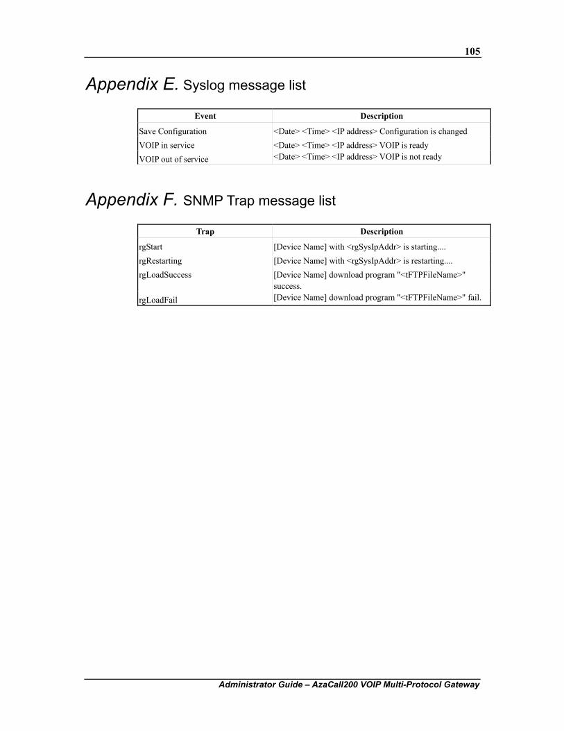
105
Administrator Guide – AzaCall200 VOIP Multi-Protocol Gateway
Appendix E. Syslog message list
Event Description
Save Configuration <Date> <Time> <IP address> Configuration is changed VOIP in service <Date> <Time> <IP address> VOIP is ready VOIP out of service <Date> <Time> <IP address> VOIP is not ready
Appendix F. SNMP Trap message list
Trap Description
rgStart [Device Name] with <rgSysIpAddr> is starting.... rgRestarting [Device Name] with <rgSysIpAddr> is restarting.... rgLoadSuccess [Device Name] download program "<tFTPFileName>"
success. rgLoadFail [Device Name] download program "<tFTPFileName>" fail.
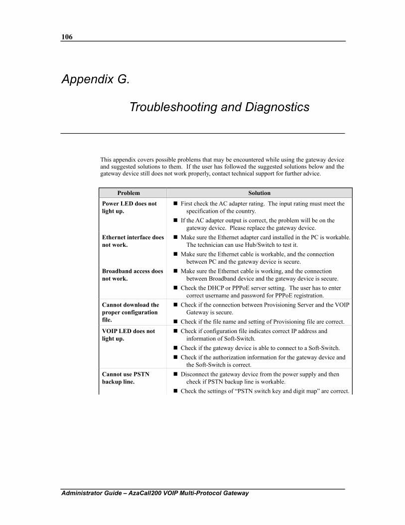
106
Administrator Guide – AzaCall200 VOIP Multi-Protocol Gateway
Appendix G. Troubleshooting and Diagnostics
This appendix covers possible problems that may be encountered while using the gateway device and suggested solutions to them. If the user has followed the suggested solutions below and the gateway device still does not work properly, contact technical support for further advice.
Problem Solution
Power LED does not light up.
First check the AC adapter rating. The input rating must meet the specification of the country.
If the AC adapter output is correct, the problem will be on the gateway device. Please replace the gateway device.
Ethernet interface does not work.
Make sure the Ethernet adapter card installed in the PC is workable. The technician can use Hub/Switch to test it.
Make sure the Ethernet cable is workable, and the connection between PC and the gateway device is secure.
Broadband access does not work.
Make sure the Ethernet cable is working, and the connection between Broadband device and the gateway device is secure.
Check the DHCP or PPPoE server setting. The user has to enter correct username and password for PPPoE registration.
Cannot download the proper configuration file.
Check if the connection between Provisioning Server and the VOIP Gateway is secure.
Check if the file name and setting of Provisioning file are correct. VOIP LED does not light up.
Check if configuration file indicates correct IP address and information of Soft-Switch.
Check if the gateway device is able to connect to a Soft-Switch. Check if the authorization information for the gateway device and
the Soft-Switch is correct. Cannot use PSTN backup line.
Disconnect the gateway device from the power supply and then check if PSTN backup line is workable.
Check the settings of “PSTN switch key and digit map” are correct.
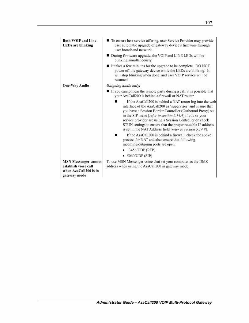
107
Administrator Guide – AzaCall200 VOIP Multi-Protocol Gateway
Both VOIP and Line LEDs are blinking
To ensure best service offering, user Service Provider may provide user automatic upgrade of gateway device’s firmware through user broadband network.
During firmware upgrade, the VOIP and LINE LEDs will be blinking simultaneously.
It takes a few minutes for the upgrade to be complete. DO NOT power off the gateway device while the LEDs are blinking. It will stop blinking when done, and user VOIP service will be resumed.
One-Way Audio Outgoing audio only: If you cannot hear the remote party during a call, it is possible that
your AzaCall200 is behind a firewall or NAT router. If the AzaCall200 is behind a NAT router log into the web
interface of the AzaCall200 as ‘supervisor’ and ensure that you have a Session Border Controller (Outbound Proxy) set in the SIP menu [refer to section 5.14.4] if you or your service provider are using a Session Controller or check STUN settings to ensure that the proper routable IP address is set in the NAT Address field [refer to section 5.14.9].
If the AzaCall200 is behind a firewall, check the above process for NAT and also ensure that following incoming/outgoing ports are open: • 13456/UDP (RTP) • 5060/UDP (SIP)
MSN Messenger cannot establish voice call when AzaCall200 is in gateway mode
To use MSN Messenger voice chat set your computer as the DMZ address when using the AzaCall200 in gateway mode.
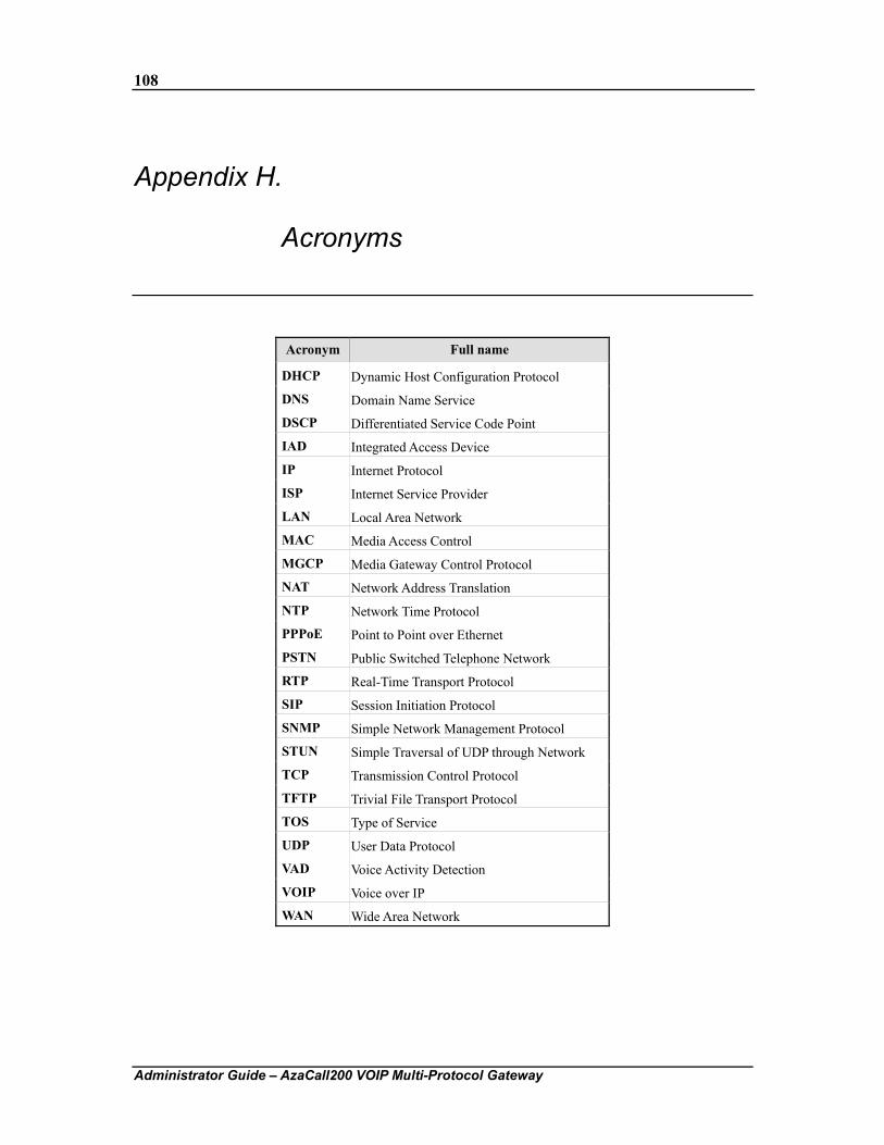
108
Administrator Guide – AzaCall200 VOIP Multi-Protocol Gateway
Appendix H. Acronyms
Acronym Full name
DHCP Dynamic Host Configuration Protocol
DNS Domain Name Service
DSCP Differentiated Service Code Point
IAD Integrated Access Device
IP Internet Protocol
ISP Internet Service Provider
LAN Local Area Network
MAC Media Access Control
MGCP Media Gateway Control Protocol
NAT Network Address Translation
NTP Network Time Protocol
PPPoE Point to Point over Ethernet
PSTN Public Switched Telephone Network
RTP Real-Time Transport Protocol
SIP Session Initiation Protocol
SNMP Simple Network Management Protocol
STUN Simple Traversal of UDP through Network
TCP Transmission Control Protocol
TFTP Trivial File Transport Protocol
TOS Type of Service
UDP User Data Protocol
VAD Voice Activity Detection
VOIP Voice over IP
WAN Wide Area Network
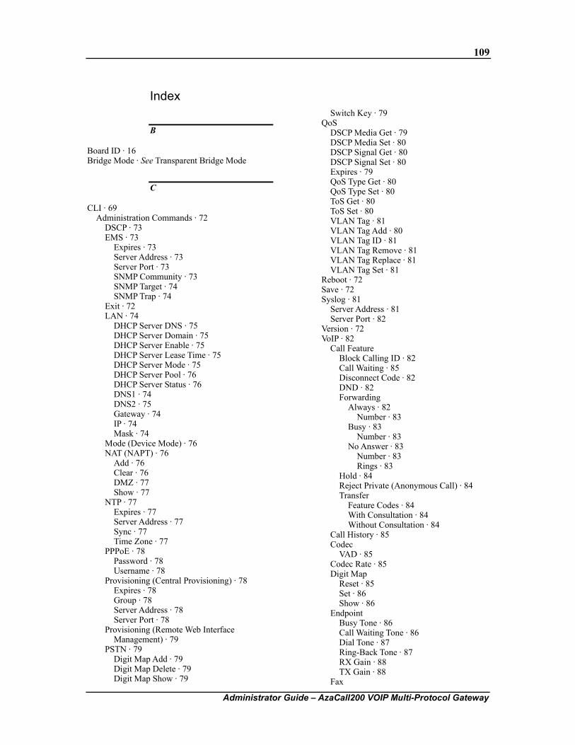
109
Administrator Guide – AzaCall200 VOIP Multi-Protocol Gateway
Index
B
Board ID · 16 Bridge Mode · See Transparent Bridge Mode
C
CLI · 69 Administration Commands · 72
DSCP · 73 EMS · 73
Expires · 73 Server Address · 73 Server Port · 73 SNMP Community · 73 SNMP Target · 74 SNMP Trap · 74
Exit · 72 LAN · 74
DHCP Server DNS · 75 DHCP Server Domain · 75 DHCP Server Enable · 75 DHCP Server Lease Time · 75 DHCP Server Mode · 75 DHCP Server Pool · 76 DHCP Server Status · 76 DNS1 · 74 DNS2 · 75 Gateway · 74 IP · 74 Mask · 74
Mode (Device Mode) · 76 NAT (NAPT) · 76
Add · 76 Clear · 76 DMZ · 77 Show · 77
NTP · 77 Expires · 77 Server Address · 77 Sync · 77 Time Zone · 77
PPPoE · 78 Password · 78 Username · 78
Provisioning (Central Provisioning) · 78 Expires · 78 Group · 78 Server Address · 78 Server Port · 78
Provisioning (Remote Web Interface Management) · 79
PSTN · 79 Digit Map Add · 79 Digit Map Delete · 79 Digit Map Show · 79
Switch Key · 79 QoS
DSCP Media Get · 79 DSCP Media Set · 80 DSCP Signal Get · 80 DSCP Signal Set · 80 Expires · 79 QoS Type Get · 80 QoS Type Set · 80 ToS Get · 80 ToS Set · 80 VLAN Tag · 81 VLAN Tag Add · 80 VLAN Tag ID · 81 VLAN Tag Remove · 81 VLAN Tag Replace · 81 VLAN Tag Set · 81
Reboot · 72 Save · 72 Syslog · 81
Server Address · 81 Server Port · 82
Version · 72 VoIP · 82
Call Feature Block Calling ID · 82 Call Waiting · 85 Disconnect Code · 82 DND · 82 Forwarding
Always · 82 Number · 83
Busy · 83 Number · 83
No Answer · 83 Number · 83 Rings · 83
Hold · 84 Reject Private (Anonymous Call) · 84 Transfer
Feature Codes · 84 With Consultation · 84 Without Consultation · 84
Call History · 85 Codec
VAD · 85 Codec Rate · 85 Digit Map
Reset · 85 Set · 86 Show · 86
Endpoint Busy Tone · 86 Call Waiting Tone · 86 Dial Tone · 87 Ring-Back Tone · 87 RX Gain · 88 TX Gain · 88
Fax
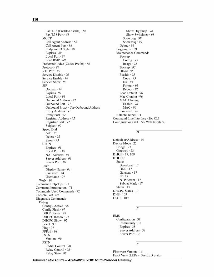
110
Administrator Guide – AzaCall200 VOIP Multi-Protocol Gateway
Fax T.38 (Enable/Disable) · 88 Fax T.38 Port · 88
MGCP Call Agent Address · 88 Call Agent Port · 88 Endpoint ID Style · 89 Expires · 89 Local Port · 89 Send RSIP · 89
Preferred Codec (Codec Prefer) · 85 Protocol · 89 RTP Port · 90 Service Disable · 90 Service Enable · 90 Service Show · 90 SIP
Domain · 90 Expires · 91 Local Port · 91 Outbound Address · 91 Outbound Port · 91 Outbound Proxy · See Outbound Address Proxy Address · 91 Proxy Port · 92 Registrar Address · 92 Registrar Port · 92 Subject · 92
Speed Dial Add · 92 Delete · 92 Show · 93
STUN Expires · 93 Local Port · 93 NAT Address · 93 Server Address · 93 Server Port · 94
User Display Name · 94 Password · 94 Username · 94
WAN · 94 Command Help/Tips · 71 Command Introduction · 71 Commonly Used Commands · 72 Console Port · 69 Diagnostic Commands
Debug Config - Active · 96 Config Flash · 97 DHCP Server · 97 DHCPC Renew · 97 DHCPC Show · 97 Level · 97 Ping · 98 PPPoE · 98 PSTN
Version · 99 PSTN
Redial Control · 98 Relay Control · 98 Relay State · 98
Show Digitmap · 98 Show Switchkey · 98
ShowLog · 99 ShowMsg · 99
Debug · 96 Logging In · 69 Maintenance Commands
Backup Config · 95 Image · 95
Backup · 95 Dload · 95 Flashfs · 95
Copy · 95 Dir · 95 Format · 95 Reboot · 96
Load Default · 96 Mac Cloning · 96 MAC Cloning
Enable · 96 MAC · 96
Password · 96 Remote Telnet · 71
Command Line Interface · See CLI Configuration GUI · See Web Interface
D
Default IP Address · 14 Device Mode · 23
Bridge · 23 Gateway · 23
DHCP · 17, 109 DHCPC
Status Braodcast · 17 DNS · 17 Gateway · 17 IP · 17 NTP Server · 17 Subnet Mask · 17
Status · 17 DHCPC Status · 17 DNS · 109 DSCP · 109
E
EMS Configuration · 38
Community · 38 Expires · 38 Server Address · 38 Server Port · 38
F
Firmware Version · 16 Front View (LEDs) · See LED Status
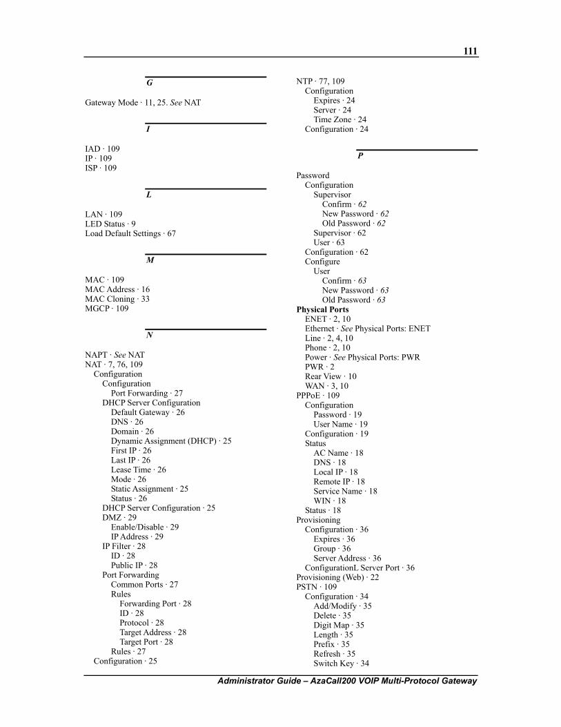
111
Administrator Guide – AzaCall200 VOIP Multi-Protocol Gateway
G
Gateway Mode · 11, 25. See NAT
I
IAD · 109 IP · 109 ISP · 109
L
LAN · 109 LED Status · 9 Load Default Settings · 67
M
MAC · 109 MAC Address · 16 MAC Cloning · 33 MGCP · 109
N
NAPT · See NAT NAT · 7, 76, 109
Configuration Configuration
Port Forwarding · 27 DHCP Server Configuration
Default Gateway · 26 DNS · 26 Domain · 26 Dynamic Assignment (DHCP) · 25 First IP · 26 Last IP · 26 Lease Time · 26 Mode · 26 Static Assignment · 25 Status · 26
DHCP Server Configuration · 25 DMZ · 29
Enable/Disable · 29 IP Address · 29
IP Filter · 28 ID · 28 Public IP · 28
Port Forwarding Common Ports · 27 Rules
Forwarding Port · 28 ID · 28 Protocol · 28 Target Address · 28 Target Port · 28
Rules · 27 Configuration · 25
NTP · 77, 109 Configuration
Expires · 24 Server · 24 Time Zone · 24
Configuration · 24
P
Password Configuration
Supervisor Confirm · 62 New Password · 62 Old Password · 62
Supervisor · 62 User · 63
Configuration · 62 Configure
User Confirm · 63 New Password · 63 Old Password · 63
Physical Ports ENET · 2, 10 Ethernet · See Physical Ports: ENET Line · 2, 4, 10 Phone · 2, 10 Power · See Physical Ports: PWR PWR · 2 Rear View · 10 WAN · 3, 10
PPPoE · 109 Configuration
Password · 19 User Name · 19
Configuration · 19 Status
AC Name · 18 DNS · 18 Local IP · 18 Remote IP · 18 Service Name · 18 WIN · 18
Status · 18 Provisioning
Configuration · 36 Expires · 36 Group · 36 Server Address · 36
ConfigurationL Server Port · 36 Provisioning (Web) · 22 PSTN · 109
Configuration · 34 Add/Modify · 35 Delete · 35 Digit Map · 35 Length · 35 Prefix · 35 Refresh · 35 Switch Key · 34
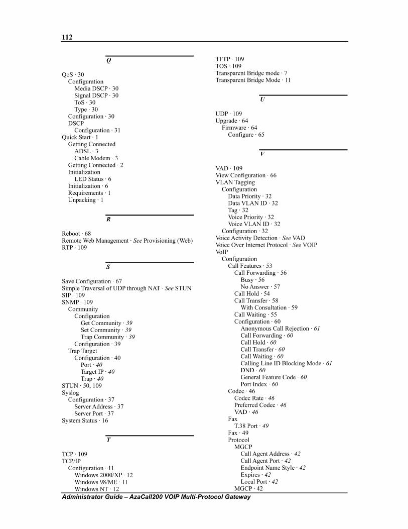
112
Administrator Guide – AzaCall200 VOIP Multi-Protocol Gateway
Q
QoS · 30 Configuration
Media DSCP · 30 Signal DSCP · 30 ToS · 30 Type · 30
Configuration · 30 DSCP
Configuration · 31 Quick Start · 1
Getting Connected ADSL · 3 Cable Modem · 3
Getting Connected · 2 Initialization
LED Status · 6 Initialization · 6 Requirements · 1 Unpacking · 1
R
Reboot · 68 Remote Web Management · See Provisioning (Web) RTP · 109
S
Save Configuration · 67 Simple Traversal of UDP through NAT · See STUN SIP · 109 SNMP · 109
Community Configuration
Get Community · 39 Set Community · 39 Trap Community · 39
Configuration · 39 Trap Target
Configuration · 40 Port · 40 Target IP · 40 Trap · 40
STUN · 50, 109 Syslog
Configuration · 37 Server Address · 37 Server Port · 37
System Status · 16
T
TCP · 109 TCP/IP
Configuration · 11 Windows 2000/XP · 12 Windows 98/ME · 11 Windows NT · 12
TFTP · 109 TOS · 109 Transparent Bridge mode · 7 Transparent Bridge Mode · 11
U
UDP · 109 Upgrade · 64
Firmware · 64 Configure · 65
V
VAD · 109 View Configuration · 66 VLAN Tagging
Configuration Data Priority · 32 Data VLAN ID · 32 Tag · 32 Voice Priority · 32 Voice VLAN ID · 32
Configuration · 32 Voice Activity Detection · See VAD Voice Over Internet Protocol · See VOIP VoIP
Configuration Call Features · 53
Call Forwarding · 56 Busy · 56 No Answer · 57
Call Hold · 54 Call Transfer · 58
With Consultation · 59 Call Waiting · 55 Configuration · 60
Anonymous Call Rejection · 61 Call Forwarding · 60 Call Hold · 60 Call Transfer · 60 Call Waiting · 60 Calling Line ID Blocking Mode · 61 DND · 60 General Feature Code · 60 Port Index · 60
Codec · 46 Codec Rate · 46 Preferred Codec · 46 VAD · 46
Fax T.38 Port · 49
Fax · 49 Protocol
MGCP Call Agent Address · 42 Call Agent Port · 42 Endpoint Name Style · 42 Expires · 42 Local Port · 42
MGCP · 42
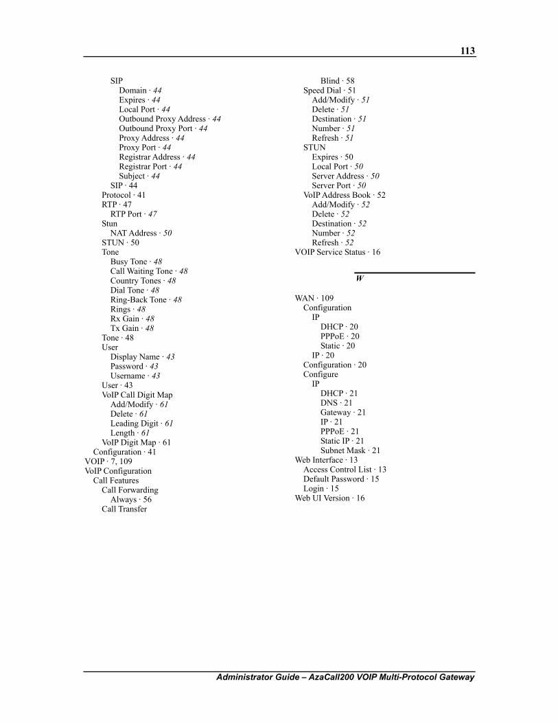
113
Administrator Guide – AzaCall200 VOIP Multi-Protocol Gateway
SIP Domain · 44 Expires · 44 Local Port · 44 Outbound Proxy Address · 44 Outbound Proxy Port · 44 Proxy Address · 44 Proxy Port · 44 Registrar Address · 44 Registrar Port · 44 Subject · 44
SIP · 44 Protocol · 41 RTP · 47
RTP Port · 47 Stun
NAT Address · 50 STUN · 50 Tone
Busy Tone · 48 Call Waiting Tone · 48 Country Tones · 48 Dial Tone · 48 Ring-Back Tone · 48 Rings · 48 Rx Gain · 48 Tx Gain · 48
Tone · 48 User
Display Name · 43 Password · 43 Username · 43
User · 43 VoIP Call Digit Map
Add/Modify · 61 Delete · 61 Leading Digit · 61 Length · 61
VoIP Digit Map · 61 Configuration · 41
VOIP · 7, 109 VoIP Configuration
Call Features Call Forwarding
Always · 56 Call Transfer
Blind · 58 Speed Dial · 51
Add/Modify · 51 Delete · 51 Destination · 51 Number · 51 Refresh · 51
STUN Expires · 50 Local Port · 50 Server Address · 50 Server Port · 50
VoIP Address Book · 52 Add/Modify · 52 Delete · 52 Destination · 52 Number · 52 Refresh · 52
VOIP Service Status · 16
W
WAN · 109 Configuration
IP DHCP · 20 PPPoE · 20 Static · 20
IP · 20 Configuration · 20 Configure
IP DHCP · 21 DNS · 21 Gateway · 21 IP · 21 PPPoE · 21 Static IP · 21 Subnet Mask · 21
Web Interface · 13 Access Control List · 13 Default Password · 15 Login · 15
Web UI Version · 16