Axial Piston Variable Pump KVA - timbertrucks.eu Motion and Hydraulics Assembly Technologies...
16
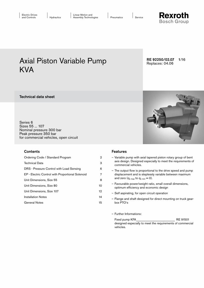
Linear Motion and Assembly Technologies Service Pneumatics Hydraulics Electric Drives and Controls Axial Piston Variable Pump KVA Technical data sheet Series 6 Sizes 55 ... 107 Nominal pressure 300 bar Peak pressure 350 bar for commercial vehicles, open circuit Features – Variable pump with axial tapered piston rotary group of bent axis design. Designed especially to meet the requirements of commercial vehicles. – The output flow is proportional to the drive speed and pump displacement and is steplessly variable between maximum and zero (q v max to q v min = 0). – Favourable power/weight ratio, small overall dimensions, optimum efficiency and economic design – Self aspirating, for open circuit operation – Flange and shaft designed for direct mounting on truck gear- box PTO‘s – Further Informations: Fixed pump KFA _________________________ RE 91501 designed especially to meet the requirements of commercial vehicles. RE 92250/02.07 /16 Replaces: 04.06 Contents Ordering Code / Standard Program 2 Technical Data 3 DRS - Pressure Control with Load Sensing 6 EP - Electric Control with Proportional Solenoid 7 Unit Dimensions, Size 55 8 Unit Dimensions, Size 80 10 Unit Dimensions, Size 107 12 Installation Notes 14 General Notes 15
Transcript of Axial Piston Variable Pump KVA - timbertrucks.eu Motion and Hydraulics Assembly Technologies...
Linear Motion andAssembly Technologies ServicePneumaticsHydraulics
Electric Drives and Controls
Axial Piston Variable Pump KVA
Technical data sheet
Series 6Sizes 55 ... 107Nominal pressure 300 barPeak pressure 350 barfor commercial vehicles, open circuit
Features– Variable pump with axial tapered piston rotary group of bent
axis design. Designed especially to meet the requirements of commercial vehicles.
– The output flow is proportional to the drive speed and pump displacement and is steplessly variable between maximum and zero (qv max to qv min = 0).
– Favourable power/weight ratio, small overall dimensions, optimum efficiency and economic design
– Self aspirating, for open circuit operation
– Flange and shaft designed for direct mounting on truck gear-box PTO‘s
– Further Informations:
Fixed pump KFA _________________________ RE 91501 designed especially to meet the requirements of commercial vehicles.
RE 92250/02.07 /16Replaces: 04.06
ContentsOrdering Code / Standard Program 2
Technical Data 3
DRS - Pressure Control with Load Sensing 6
EP - Electric Control with Proportional Solenoid 7
Unit Dimensions, Size 55 8
Unit Dimensions, Size 80 10
Unit Dimensions, Size 107 12
Installation Notes 14
General Notes 15
2/16 Bosch Rexroth AG KVA RE 92250/02.07
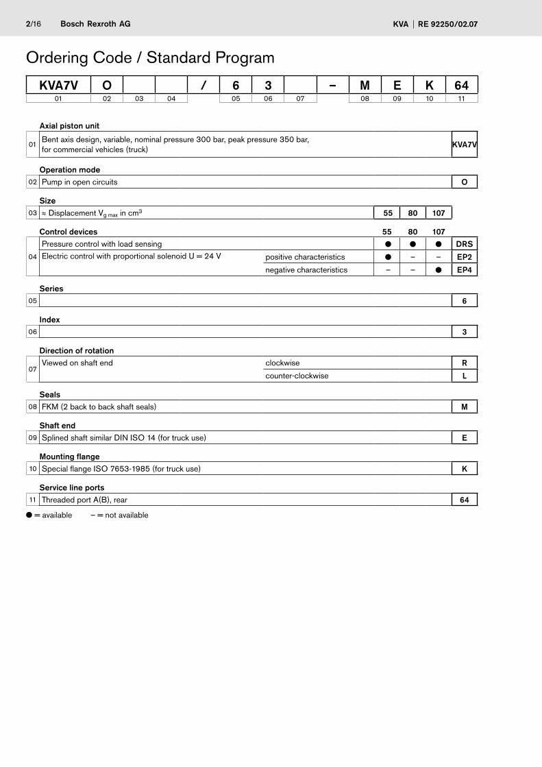
Ordering Code / Standard Program
Axial piston unit
01Bent axis design, variable, nominal pressure 300 bar, peak pressure 350 bar, for commercial vehicles (truck) KVA7V
Operation mode02 Pump in open circuits O
Size03 ≈ Displacement Vg max in cm3 55 80 07
Control devices 55 80 07
04
Pressure control with load sensing DRSElectric control with proportional solenoid U = 24 V positive characteristics – – EP2
negative characteristics – – EP4
Series05 6
Index06 3
Direction of rotation
07Viewed on shaft end clockwise R
counter-clockwise L
Seals08 FKM (2 back to back shaft seals) M
Shaft end09 Splined shaft similar DIN ISO 14 (for truck use) E
Mounting flange10 Special flange ISO 7653-1985 (for truck use) K
Service line ports11 Threaded port A(B), rear 64
= available – = not available
KVA7V O / 6 3 – M E K 6401 02 03 04 05 06 07 08 09 10 11
Bosch Rexroth AGRE 92250/02.07 KVA 3/16
Technical DataHydraulic fluidBefore starting project planning, please refer to our data sheets RE 90220 (mineral oil) and RE 90221 (environmentally acceptable hydraulic fluids) for detailed information regarding the choice of hydraulic fluids and conditions of use.
If environmentally acceptable hydraulic fluids are being used, the limitations regarding technical data and seals mentioned in RE 90221 must be observed.
When ordering please indicate the used hydraulic fluid.
Attention: For the operation with water-containing HF-fluids the variable pump KVA is not suitable.
Viscosity range
We recommend that a viscosity (at operating temperature) for optimum efficiency and service life purposes of
νopt = opt. operating viscosity 16...36 mm2/s
be chosen, taken the tank temperature (open circuits) into account.
Limits of viscosity range
The following values apply in extreme cases:
νmin = 5 mm2/s short term (t < 3 min.) at max. permitted temperature tmax = 115°C.
νmax = 1600 mm2/s short term (t < 3 min.) with cold start (p < 30 bar, n ≤ 1000 rpm, tmin = -25°C).
Note that the maximum hydraulic fluid temperature of 115°C must not be exceeded locally either (e.g. bearing area). The temperature in the bearing area is - depending on pressure and speed - up to 12 K higher than the average case drain tempe-rature.
This axial piston unit can not be operated in a temperature range of less than -25°C.
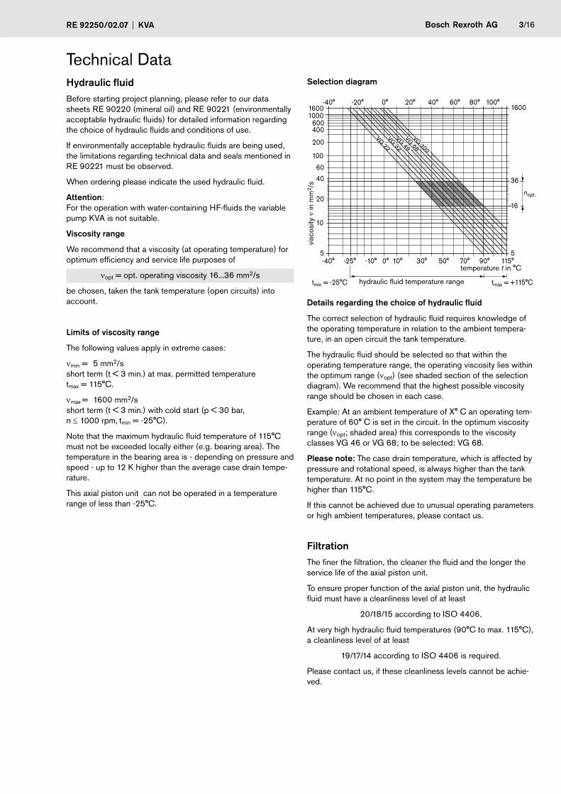
Selection diagram
tmin = -25°C tmax = +115°C
-40° -25° -10° 10° 30° 50° 90° 115° 70° 0°5
10
4060
20
100
200
400 600
1000 1600
-40° 0° 20° 40° 60° 80° 100° -20°1600
nopt.
16
36 VG
22 VG
32 VG
46 VG
68 VG
100
5
hydraulic fluid temperature range
temperature t in °C
visc
osity
ν in
mm
2 /s
Details regarding the choice of hydraulic fluid
The correct selection of hydraulic fluid requires knowledge of the operating temperature in relation to the ambient tempera-ture, in an open circuit the tank temperature.
The hydraulic fluid should be selected so that within the operating temperature range, the operating viscosity lies within the optimum range (νopt) (see shaded section of the selection diagram). We recommend that the highest possible viscosity range should be chosen in each case.
Example: At an ambient temperature of X° C an operating tem-perature of 60° C is set in the circuit. In the optimum viscosity range (νopt; shaded area) this corresponds to the viscosity classes VG 46 or VG 68; to be selected: VG 68.
Please note: The case drain temperature, which is affected by pressure and rotational speed, is always higher than the tank temperature. At no point in the system may the temperature be higher than 115°C.
If this cannot be achieved due to unusual operating parameters or high ambient temperatures, please contact us.
FiltrationThe finer the filtration, the cleaner the fluid and the longer the service life of the axial piston unit.
To ensure proper function of the axial piston unit, the hydraulic fluid must have a cleanliness level of at least
20/18/15 according to ISO 4406.
At very high hydraulic fluid temperatures (90°C to max. 115°C), a cleanliness level of at least
19/17/14 according to ISO 4406 is required.
Please contact us, if these cleanliness levels cannot be achie-ved.
4/16 Bosch Rexroth AG KVA RE 92250/02.07
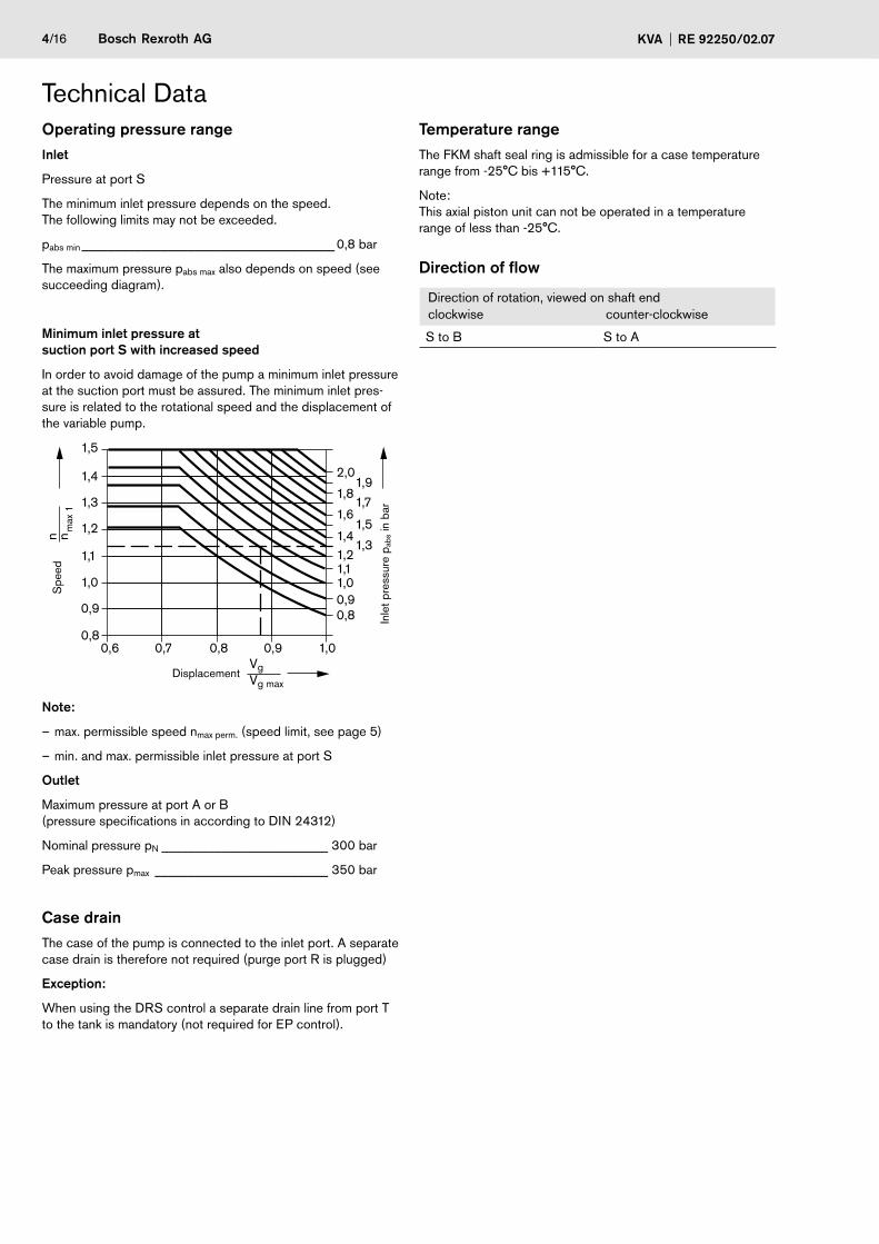
Technical DataOperating pressure rangeInlet
Pressure at port S
The minimum inlet pressure depends on the speed. The following limits may not be exceeded.
pabs min ______________________________________ 0,8 bar
The maximum pressure pabs max also depends on speed (see succeeding diagram).
Minimum inlet pressure at suction port S with increased speed
In order to avoid damage of the pump a minimum inlet pressure at the suction port must be assured. The minimum inlet pres-sure is related to the rotational speed and the displacement of the variable pump.
0,6 0,7 0,8 0,9 1,0
2,0
1,8
1,6
1,41,21,11,00,90,8
1,91,7
1,5
1,3
1,5
1,4
1,3
1,2
1,1
1,0
0,9
0,8
n nm
ax 1
VgVg max
Displacement
Inle
t pre
ssur
e p a
bs in
bar
Spe
ed
Note:
– max. permissible speed nmax perm. (speed limit, see page 5)
– min. and max. permissible inlet pressure at port S
Outlet
Maximum pressure at port A or B (pressure specifications in according to DIN 24312)
Nominal pressure pN _________________________ 300 bar
Peak pressure pmax __________________________ 350 bar
Case drainThe case of the pump is connected to the inlet port. A separate case drain is therefore not required (purge port R is plugged)
Exception:
When using the DRS control a separate drain line from port T to the tank is mandatory (not required for EP control).
Temperature rangeThe FKM shaft seal ring is admissible for a case temperature range from -25°C bis +115°C.
Note: This axial piston unit can not be operated in a temperature range of less than -25°C.
Direction of flow
Direction of rotation, viewed on shaft endclockwise counter-clockwise
S to B S to A
Bosch Rexroth AGRE 92250/02.07 KVA 5/16
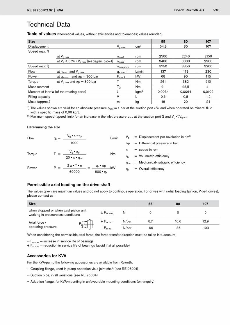
Table of values (theoretical values, without efficiencies and tolerances; values rounded)
Size 55 80 07Displacement Vg max cm3 54,8 80 107Speed max. 1)
at Vg max nmax1 rpm 2500 2240 2150at Vg < 0,74 • Vg max (see diagram, page 4) nmax2 rpm 3400 3000 2900
Speed max. 2) nmax perm. rpm 3750 3350 3200
Flow at nmax 1 and Vg max qv max 1 L/min 137 179 230Power at qv max 1 and Δp = 300 bar Pmax 1 kW 68 90 115
Torque at Vg max and Δp = 300 bar T Nm 261 382 510
Mass moment TG Nm 21 28,5 41Moment of inertia (of the rotating parts) J kgm2 0,0034 0,0064 0,0102Filling capacity V L 0,6 0,8 1,2Mass (approx.) m kg 16 20 24
1) The values shown are valid for an absolute pressure pabs = 1 bar at the suction port »S« and when operated on mineral fluid with a specific mass of 0,88 kg/L. 2) Maximum speed (speed limit) for an increase in the inlet pressure pabs at the suction port S and Vg < Vg max
Determining the size
Flow qv =Vg • n • ηv L/min
1000
Torque T = Vg • Δp Nm
20 • π • ηmh
Power P =2 π • T • n
=qv • Δp
kW60000 600 • ηt
Permissible axial loading on the drive shaftThe values given are maximum values and do not apply to continous operation. For drives with radial loading (pinion, V-belt drives), please contact us!
Size 55 80 07
when stopped or when axial piston unit working in pressureless conditions
± Fax max N 0 0 0
Axial force / operating pressure
Fax–
+
+ Fax zul.
− Fax zul.
N/bar 8,7 10,6 12,9
N/bar -66 -86 -103
When considering the permissible axial force, the force-transfer direction must be taken into account:
− Fax max = increase in service life of bearings + Fax max = reduction in service life of bearings (avoid if at all possible)
Accessories for KVAFor the KVA-pump the following accessories are available from Rexroth:
– Coupling flange, used in pump operation via a joint shaft (see RE 95001)
– Suction pipe, in all variations (see RE 95004)
– Adaption flange, for KVA-mounting in unfavourable mounting conditions (on enquiry)
Technical Data
Vg = Displacement per revolution in cm3
Δp = Differential pressure in bar
n = speed in rpm
ηv = Volumetric efficiency
ηmh = Mechanical-hydraulic efficiency
ηt = Overall efficiency

6/16 Bosch Rexroth AG KVA RE 92250/02.07
DRS - Pressure Control with Load SensingFunction of the pressure controlThe pressure control keeps the pressure in a hydraulic system constant within its control range even under varying flow condi-tions. The variable pump only moves as much hydraulic fluid as is required by the actuators. If the operating pressure exceeds the setpoint set at the integral pressure control valve, the pump displacement is automatically swivelled back until the pressure deviation is corrected.
In zero pressure non-running condition, the pump is swivelled to its starting position Vg max by means of the control spring.
Setting range for pressure control _________ 80 to 320 bar
Standard setting: ____________________________ 300 bar
Note: Any pressure relief vlave included in the circuit to limit the max. pressure must be set to a cracking pressure at least 20 bar above the pressure control setting.
The pressure control is superimposed on the load sensing valve, i.e. the load sensing function operates below the set pressure.
Load sense functionThe load sensing control is a flow control option that operates as a function of the load pressure to regulate the pump dis-placement to match the actuator flow requirement.
The flow depends here on the cross section of the external sensing orifice (1) fitted between the pump outlet and the actuator. The flow is independent of the load pressure below the pressure cut-off setting and within the control range of the pump.
The sensing orifice is usually a separately arranged load sensing directional valve (control block). The position of the directional valve piston determines the opening cross section of the sensing orifice and thus the flow of the pump.
The load sensing control compares pressure before and after the sensing orifice and maintains the pressure drop across the orifice - and therefore the pump flow - constant as a function of the orifice size.
If the differential pressure Δp increases, the pump is swivel-led back towards Vg min and, if the Δp decreases the pump is swivelling out towards Vg max until the pressure drop across the sensing orifice in the valve is restored.
Δporifice = ppump – pactuator
Setting range for Δp: ______________________19 ... 40 bar
Standard setting: _____________________________ 30 bar
The stand-by pressure in zero stroke operation (sensing orifice plugged) is slightly above the Δp setting.
(1) The sensing orifice (control block) is not included in the pump supply.
Characteristic DRS
350
50
max
. 10
bar
min
max
Displacement
Ope
ratin
g pr
essu
re p
B in
bar
Vg min Vg max
Circuit diagram DRS
R
X T
A (B)Vg min Vg max A1
R1
S
(1)
Zero stroke operationThe standard pump unit is designed for intermittent constant pressure operation. Short-term operation at zero stroke (< 10 min.) is permissible up to a operating pressure pmax = 300 bar at a tank temperature of ≤ 50°C.
Note: When using the DRS control a drain line is mandatory from the T port to tank to maintain thermal stability.
When ordering, state in clear text:
- Setting of the pressure control - Δp - setting of the load sensing function
(If there is no clear specification, pump will be delivered with standard setting, see above.)
Bosch Rexroth AGRE 92250/02.07 KVA 7/16
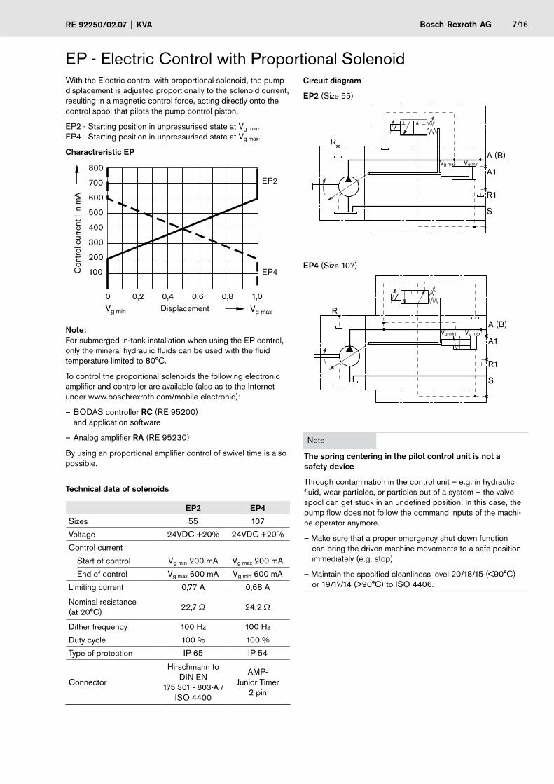
EP - Electric Control with Proportional SolenoidWith the Electric control with proportional solenoid, the pump displacement is adjusted proportionally to the solenoid current, resulting in a magnetic control force, acting directly onto the control spool that pilots the pump control piston.
EP2 - Starting position in unpressurised state at Vg min. EP4 - Starting position in unpressurised state at Vg max.
Charactreristic EP
800
700
600
500
400
300
200
100
0 0,2 0,4 0,6 0,8 1,0 Vg min Vg max Displacement
Con
trol
cur
rent
I in
mA
EP2
EP4
Note: For submerged in-tank installation when using the EP control, only the mineral hydraulic fluids can be used with the fluid temperature limited to 80°C.
To control the proportional solenoids the following electronic amplifier and controller are available (also as to the Internet under www.boschrexroth.com/mobile-electronic):
– BODAS controller RC (RE 95200) and application software
– Analog amplifier RA (RE 95230)
By using an proportional amplifier control of swivel time is also possible.
Technical data of solenoids
EP2 EP4
Sizes 55 107
Voltage 24VDC +20% 24VDC +20%
Control current
Start of control Vg min 200 mA Vg max 200 mA
End of control Vg max 600 mA Vg min 600 mA
Limiting current 0,77 A 0,68 A
Nominal resistance (at 20°C)
22,7 Ω 24,2 Ω
Dither frequency 100 Hz 100 Hz
Duty cycle 100 % 100 %
Type of protection IP 65 IP 54
Connector
Hirschmann to DIN EN
175 301 - 803-A / ISO 4400
AMP- Junior Timer
2 pin
Circuit diagram
EP2 (Size 55)
R
A (B) Vg max Vg min
A1
R1
S
EP4 (Size 107)
R
A (B) Vg min Vg max
A1
R1
S
Note
The spring centering in the pilot control unit is not a safety device
Through contamination in the control unit – e.g. in hydraulic fluid, wear particles, or particles out of a system – the valve spool can get stuck in an undefined position. In this case, the pump flow does not follow the command inputs of the machi-ne operator anymore.
– Make sure that a proper emergency shut down function can bring the driven machine movements to a safe position immediately (e.g. stop).
– Maintain the specified cleanliness level 20/18/15 (<90°C) or 19/17/14 (>90°C) to ISO 4406.
8/16 Bosch Rexroth AG KVA RE 92250/02.07
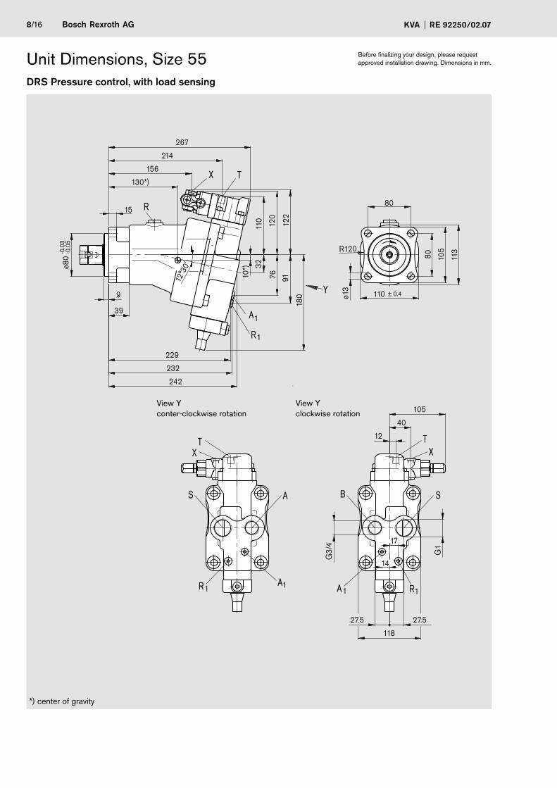
Unit Dimensions, Size 55 Before finalizing your design, please request approved installation drawing. Dimensions in mm.
DRS Pressure control, with load sensing
1A1R 1R
TX
S A
T
1A
X
R
Y
1A
TX
B S
1R
91
229
R120
17
10*)
113
14
105
40
12
G3/
4
G1
118
27.5 27.5
-0.0
5-0
.03
ø80
± 0.4110
105
80
80
ø13
122
120
110
32
12°3
0'
76
180
39
9
15
156
130*)
214
267
242
232
*) center of gravity
View Y conter-clockwise rotation
View Y clockwise rotation
Bosch Rexroth AGRE 92250/02.07 KVA 9/16
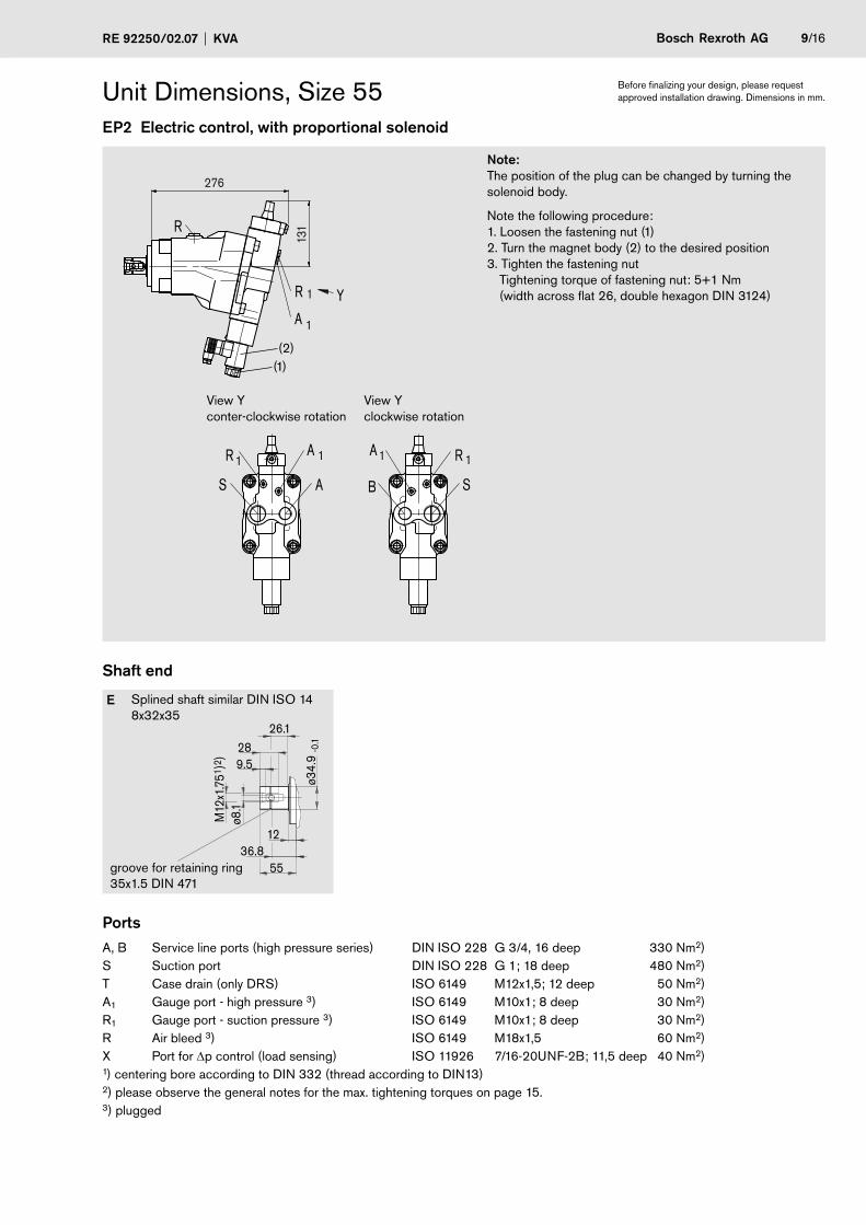
Unit Dimensions, Size 55EP2 Electric control, with proportional solenoid
1A
1R
R
Y
1R1A
B S
1R 1A
AS
131
276
Shaft end
E Splined shaft similar DIN ISO 14 8x32x35
PortsA, B Service line ports (high pressure series) DIN ISO 228 G 3/4, 16 deep 330 Nm2)S Suction port DIN ISO 228 G 1; 18 deep 480 Nm2)T Case drain (only DRS) ISO 6149 M12x1,5; 12 deep 50 Nm2)A1 Gauge port - high pressure 3) ISO 6149 M10x1; 8 deep 30 Nm2)R1 Gauge port - suction pressure 3) ISO 6149 M10x1; 8 deep 30 Nm2)R Air bleed 3) ISO 6149 M18x1,5 60 Nm2)X Port for Δp control (load sensing) ISO 11926 7/16-20UNF-2B; 11,5 deep 40 Nm2)1) centering bore according to DIN 332 (thread according to DIN13)2) please observe the general notes for the max. tightening torques on page 15.3) plugged
9.5
12 36.8
ø34.
9-0
.1
M12
x1.7
51)2
)
26.1 28
55
ø8.1
groove for retaining ring 35x1.5 DIN 471
(1)(2)
Before finalizing your design, please request approved installation drawing. Dimensions in mm.
View Y conter-clockwise rotation
View Y clockwise rotation
Note: The position of the plug can be changed by turning the solenoid body.
Note the following procedure: 1. Loosen the fastening nut (1) 2. Turn the magnet body (2) to the desired position 3. Tighten the fastening nut Tightening torque of fastening nut: 5+1 Nm (width across flat 26, double hexagon DIN 3124)
0/16 Bosch Rexroth AG KVA RE 92250/02.07
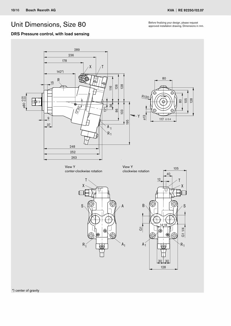
Unit Dimensions, Size 80DRS Pressure control, with load sensing
R120
103
18
248
12*)
128
14
105
40
12
G1
G1
1/4
128
30 30
-0.0
5-0
.03
ø80
± 0.4117
105
80
80
ø13
128
126
116
36
12°3
0'
86
195
37
9
15
178
142*)
236
289
263
252
1A
TX
S A
1R
T
1A
X
R
Y
1A
TX
B S
1R
1R
*) center of gravity
Before finalizing your design, please request approved installation drawing. Dimensions in mm.
View Y conter-clockwise rotation
View Y clockwise rotation
Bosch Rexroth AGRE 92250/02.07 KVA /16
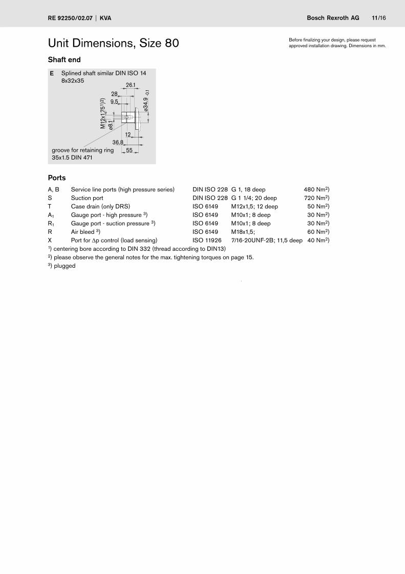
Unit Dimensions, Size 80Shaft end
E Splined shaft similar DIN ISO 14 8x32x35
PortsA, B Service line ports (high pressure series) DIN ISO 228 G 1, 18 deep 480 Nm2)S Suction port DIN ISO 228 G 1 1/4; 20 deep 720 Nm2)T Case drain (only DRS) ISO 6149 M12x1,5; 12 deep 50 Nm2)A1 Gauge port - high pressure 3) ISO 6149 M10x1; 8 deep 30 Nm2)R1 Gauge port - suction pressure 3) ISO 6149 M10x1; 8 deep 30 Nm2)R Air bleed 3) ISO 6149 M18x1,5; 60 Nm2)X Port for Δp control (load sensing) ISO 11926 7/16-20UNF-2B; 11,5 deep 40 Nm2)1) centering bore according to DIN 332 (thread according to DIN13)2) please observe the general notes for the max. tightening torques on page 15.3) plugged
9.5
12 36.8
ø34.
9-0
.1
M12
x1.7
51)2
)
26.1 28
55
ø8.1
groove for retaining ring 35x1.5 DIN 471
Before finalizing your design, please request approved installation drawing. Dimensions in mm.
2/16 Bosch Rexroth AG KVA RE 92250/02.07
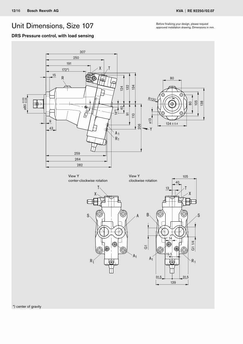
Unit Dimensions, Size 107DRS Pressure control, with load sensing
19.5
259
110
172*)
14*)
264
91
206
-0.0
6-0
.03
ø80
15
307
282
43
9
250
132
191
40
134
± 0.4124
80
ø13
R120
138
105
80
G1
G1
1/4
13931.5 31.5
13
40
105
12°3
0'
124
14
T
S A
1A
X
1R
T
T
R
X
B S
1A
X
Y1A1R
1R
*) center of gravity
Before finalizing your design, please request approved installation drawing. Dimensions in mm.
View Y conter-clockwise rotation
View Y clockwise rotation

Bosch Rexroth AGRE 92250/02.07 KVA 3/16
Unit Dimensions, Size 107EP4 Electric control, with proportional solenoid
1A
1R
R
B S
1A 1R
Y
S A
1R 1A
178
306
Shaft end
E Splined shaft similar DIN ISO 14 8x32x35
PortsA, B Service line ports (high pressure series) DIN ISO 228 G 1, 18 deep 480 Nm2)S Suction port DIN ISO 228 G 1 1/4; 20 deep 720 Nm2)T Case drain (only DRS) ISO 6149 M12x1,5; 12 deep 50 Nm2)A1 Gauge port - high pressure 3) ISO 6149 M10x1; 8 deep 30 Nm2)R1 Gauge port - suction pressure 3) ISO 6149 M10x1; 8 deep 30 Nm2)R Air bleed 3) ISO 6149 M18x1,5; 60 Nm2)X Port for Δp control (load sensing) ISO 11926 7/16-20UNF-2B; 11,5 deep 40 Nm2)1) centering bore according to DIN 332 (thread according to DIN13)2) please observe the general notes for the max. tightening torques on page 15.3) plugged
9.5
12 36.8
ø34.
9-0
.1
M12
x1.7
51)2
)
26.1 28
55
ø8.1
groove for retaining ring 35x1.5 DIN 471
Before finalizing your design, please request approved installation drawing. Dimensions in mm.
View Y conter-clockwise rotation
View Y clockwise rotation
4/16 Bosch Rexroth AG KVA RE 92250/02.07
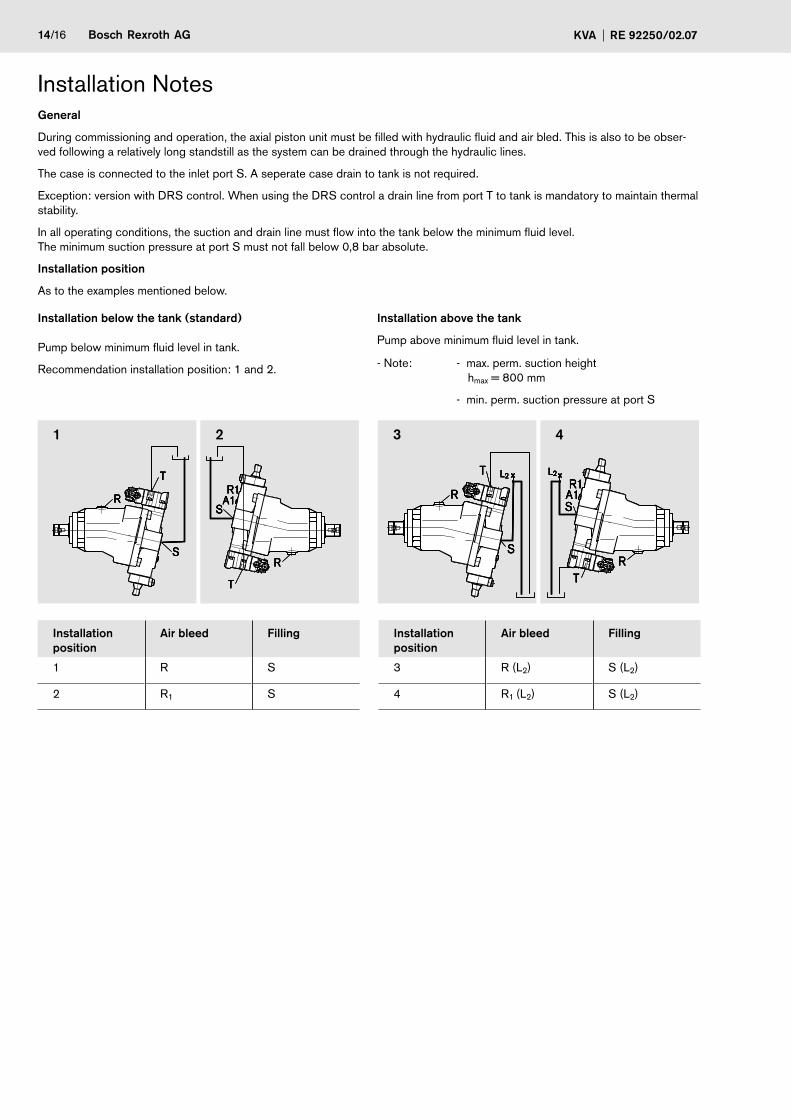
General
During commissioning and operation, the axial piston unit must be filled with hydraulic fluid and air bled. This is also to be obser-ved following a relatively long standstill as the system can be drained through the hydraulic lines.
The case is connected to the inlet port S. A seperate case drain to tank is not required.
Exception: version with DRS control. When using the DRS control a drain line from port T to tank is mandatory to maintain thermal stability.
In all operating conditions, the suction and drain line must flow into the tank below the minimum fluid level. The minimum suction pressure at port S must not fall below 0,8 bar absolute.
Installation position
As to the examples mentioned below.
Installation below the tank (standard)
Pump below minimum fluid level in tank.
Recommendation installation position: 1 and 2.
Installation above the tank
Pump above minimum fluid level in tank.
- Note: - max. perm. suction height hmax = 800 mm
- min. perm. suction pressure at port S
2 3 4
Installation position
Air bleed Filling Installation position
Air bleed Filling
1 R S 3 R (L2) S (L2)
2 R1 S 4 R1 (L2) S (L2)
T
S
R
T
S
R1A1
R
T
S
R
T
S
R1A1
R
T
S
R
T
S
R1A1
R
T
S
R
T
S
R1A1
R
T
S
R
L2
T
S
R1A1
R
L2T
S
R
L2
T
S
R1A1
R
L2T
S
R
L2
T
S
R1A1
R
L2T
S
R
L2
T
S
R1A1
R
L2
Installation Notes

Bosch Rexroth AGRE 92250/02.07 KVA 5/16
– The KVA pump is designed to be used in open circuits.
– Project planning, assembly and commissioning of the pump require the involvement of trained personnel.
– The working and functional ports are only designed to accommodate hydraulic piping.
– There is a danger of burns from the pump and especially the solenoids during and shortly after operation. Suitable safety precautions, e.g. protective clothing plan.
– The characteristic curve may shift depending on the operating status (operating pressure, fluid temperature) of the pump.
– Tightening torques: - The tightening torques specified in this data sheet are maximum values and may not be exceeded (maximum value for screw thread). Manufacturer specifications for the max. permissible tightening torques of the used fittings must be observed! - For DIN 13 fastening screws we recommend checking the tightening torque individually according to VDI 2230 Edition 2003.
– The data and information contained herein must be adhered to.
General Notes

6/16 Bosch Rexroth AG KVA RE 92250/02.07
Bosch Rexroth AG HydraulicsProduct Segment Axial Piston UnitsElchingen PlantGlockeraustraße 2 89275 Elchingen, Germany Phone +49 (0) 73 08 82-0 Facsimile +49 (0) 73 08 72 [email protected] www.boschrexroth.com/axial-piston-pumps
© This document, as well as the data, specifications and other information set forth in it, are the exclusive property of Bosch Rexroth AG. It may not be reproduced or given to third parties without its consent.
The data specified above only serve to describe the product. No statements concerning a certain condition or suitability for a certain application can be derived from our information. The information given does not release the user from the obligation of own judgment and verification. It must be remembered that our products are subject to a natural process of wear and aging.
Subject to change.