
Axial Piston Variable Pump A18VO Series 11 - Interempresas · PDF fileRE 92270/06.2012, Bosch...
24
RE 92270/06.2012, Bosch Rexroth AG Features ▶ Variable pump with axial tapered piston rotary group of bent-axis design with special characteristics and dimen- sions for use in commercial vehicles. ▶ The flow is proportional to the drive speed and displace- ment. ▶ The flow can be infinitely varied by adjusting the bent- axis angle. ▶ Favorable power-to-weight ratio, compact dimensions, optimum efficiency, economical design ▶ High self-suction capability ▶ Flange and shaft designed for direct mounting on the power take-off of commercial vehicles ▶ Low noise levels ▶ Increased pressure (350/400 bar) compared to standard pump A17VO ▶ Sizes 55 to 107 ▶ Nominal pressure 350 bar ▶ Maximum pressure 400 bar ▶ For commercial vehicles ▶ Open circuit Axial Piston Variable Pump A18VO Series 11 RE 92270 Issue: 06.2012 Replaces: 06.2009 Contents Ordering code 2 Technical data 3 DRS – Pressure controller with load sensing 8 EP – Proportional control electric 10 Dimensions size 55 12 Dimensions size 80 14 Dimensions size 107 16 Suction stud 19 Coupling flange 20 Connector for solenoids 21 Installation instructions 22 Other related documents 23 General instructions 24
Transcript of Axial Piston Variable Pump A18VO Series 11 - Interempresas · PDF fileRE 92270/06.2012, Bosch...

RE 92270/06.2012, Bosch Rexroth AG
Features Variable pump with axial tapered piston rotary group of
bent-axis design with special characteristics and dimen-sions for use in commercial vehicles.
The flow is proportional to the drive speed and displace-ment.
The flow can be infinitely varied by adjusting the bent-axis angle.
Favorable power-to-weight ratio, compact dimensions, optimum efficiency, economical design
High self-suction capability Flange and shaft designed for direct mounting on the
power take-off of commercial vehicles Low noise levels Increased pressure (350/400 bar) compared to standard
pump A17VO
Sizes 55 to 107 Nominal pressure 350 bar Maximum pressure 400 bar For commercial vehicles Open circuit
Axial Piston Variable PumpA18VO Series 11
RE 92270Issue: 06.2012Replaces: 06.2009
ContentsOrdering code 2Technical data 3DRS – Pressure controller with load sensing 8EP – Proportional control electric 10Dimensions size 55 12Dimensions size 80 14Dimensions size 107 16Suction stud 19Coupling flange 20Connector for solenoids 21Installation instructions 22Other related documents 23General instructions 24

2 A18VO Series 11 | Ordering code
Bosch Rexroth AG, RE 92270/06.2012
Ordering code
01 02 03 04 05 06 07 08 09 10 11 12 13 14 15
A18V O 0 / 11 N W K0 0 –
Axial piston unit
01 Bent-axis design, variable, nominal pressure 350 bar, maximum pressure 400 bar, for commercial vehicles (trucks) A18V
Operating mode
02 Pump, open circuit O
Sizes (NG)
03 Geometric displacement, see table of values on page 6 055 080 107
Control devices 055 080 107
04 Pressure controller with load sensing DRS
Proportional control electric positive control U = 24 V EP2
negative control U = 24 V EP6
Connector for solenoids (see page 21)
05 Without connector (without solenoid, only for hydraulic controller) 0
DEUTSCH – molded connector, 2-pin – without suppressor diode P
Additional functions 1
06 Without additional functions 0
Series
07 Series 1, index 1 11
Configuration of ports and fastening threads
08 Metric, port threads with profiled sealing ring according to DIN 3852 N
Directions of rotation
09 Viewed on drive shaft clockwise R
counter-clockwise L
Seals
10 FKM (fluor-caoutchouc) including the 2 shaft seal rings in FKM W
Mounting flange
11 Special flange ISO 7653-1985 (for trucks) K0
Drive shaft
12 Splined shaft similar to DIN ISO 14 (for trucks) E8
Splined shaft E8 with coupling flange C8
Port plate for service lines
13 Threaded ports A and S at rear 1
Threaded ports A and S at rear, with suction stud mounted in S 2
Auxiliary functions 2
14 Without auxiliary functions 0
Standard / special version
15 Standard version 0
Special version S
= Available = On request

Technical data | A18VO Series 11 3
RE 92270/06.2012, Bosch Rexroth AG
Technical data
Hydraulic fluidBefore starting project planning, please refer to our data sheets RE 90220 (mineral oil) and RE 90221 (environmen-tally acceptable hydraulic fluids) for detailed information regarding the choice of hydraulic fluid and application conditions.If environmentally acceptable hydraulic fluids are used, the limitations regarding technical data or other seals must be observed. Please contact us.
NoteVariable pump A18VO is not suitable for operation with water-containing HF hydraulic fluid.
Selection diagram
-40° -25° -10° 10° 30° 50° 90° 115°70°0°5
10
4060
20
100
200
400600
10001600
-40° 0° 20° 40° 60° 80° 100°-20°1600
νopt
16
36
VG 22VG 32VG 46VG 68VG 100
5
Visc
osity
ν [
mm
2 /s]
tmin = -40 °C Hydraulic fluid temperature range tmax = +115 °C
Temperature t [°C]
Details regarding the choice of hydraulic fluidThe correct choice of hydraulic fluid requires knowledge of the operating temperature in relation to the ambient tem-perature: in an open circuit the reservoir temperature.The hydraulic fluid should be chosen so that the operating viscosity in the operating temperature range is within the optimum range (νopt see shaded area of the selection dia-gram). We recommended that the higher viscosity class be selected in each case.Example: At an ambient temperature of X °C, an operating temperature of 60 °C is set in the circuit. In the optimum operating viscosity range (νopt, shaded area), this corre-sponds to the viscosity classes VG 46 or VG 68; to be selected: VG 68.
NoteThe case drain temperature, which is affected by pressure and speed, can be higher than the reservoir temperature. At no point of the component may the temperature be higher than 115 °C. The temperature difference specified below is to be taken into account when determining the viscosity in the bearing.If the above conditions cannot be maintained due to extreme operating parameters, please contact us.
Viscosity and temperature of hydraulic fluid
Viscosity [mm2/s] Temperature Comment
Transport and storage at ambient temperature
Tmin ≥ -40 °C Topt = +5 °C to +20 °C
factory preservation: up to 12 months with standard, up to 24 months with long-term
(Cold) start-up νmax = 1600 TSt ≥ -40 °C t ≤ 3 min, without load (p ≤ 50 bar), n ≤ 1000 rpm
Permissible temperature difference ΔT ≤ 25 K between axial piston unit and hydraulic fluid
Warm-up phase ν < 1600 to 400 T = -40 °C to -25 °C at p ≤ 0.7 • pnom, n ≤ 0.5 • nnom and t ≤ 15 min
Operating phase
Temperature difference ΔT = approx. 12 K between hydraulic fluid in the bearing and at port R
Maximum temperature 115 °C in the bearing
103 °C measured at port R
Continuous operation ν = 400 to 10 νopt = 36 to 16
T = -25 °C to +90 °C measured at port R, no restriction within the permissible data
Short-term operation νmin ≥ 7 Tmax = +103 °C measured at port R, t < 3 min, p < 0.3 • pnom
Shaft seal FKM T ≤ +115 °C see page 4

4 A18VO Series 11 | Technical data
Bosch Rexroth AG, RE 92270/06.2012
Filtration of the hydraulic fluidFiner filtration improves the cleanliness level of the hydrau-lic fluid, which increases the service life of the axial piston unit. To ensure the functional reliability of the axial piston unit, a gravimetric analysis of the hydraulic fluid is necessary to determine the amount of solid contaminant and to deter-mine the cleanliness level according to ISO 4406. A cleanli-ness level of at least 20/18/15 is to be maintained.At very high hydraulic fluid temperatures (90 °C to maxi-mum 115 °C), a cleanliness level of at least 19/17/14 according to ISO 4406 is necessary. If the above classes cannot be achieved, please contact us.
Case drain fluidThe case drain chamber is connected to the suction cham-ber. A case drain line from the case to the reservoir is not required (port "R" is plugged). On versions with DRS control, a case drain line for dis-charge from port "T" to the reservoir is absolutely essential (not necessary for EP control).
Shaft sealThe FKM shaft seal may be used for case drain tempera-tures from -25 °C to +115 °C.
NoteFor the temperature range below -25 °C, the values in the table on page 3 are to be observed.

Technical data | A18VO Series 11 5
RE 92270/06.2012, Bosch Rexroth AG
Operating pressure rangeValid when using hydraulic fluids based on mineral oils
Pressure at service line port A Definition
Nominal pressure pnom 350 bar absolute The nominal pressure corresponds to the maximum design pressure.
Maximum pressure pmax 400 bar absolute The maximum pressure corresponds to the maximum operating pressure within the single operating period. The sum of the single operating periods must not ex-ceed the total operating period.
Single operating period 5 s
Total operating period 50 h
Minimum pressure (high-pressure side)
10 bar absolute Minimum pressure at the high-pressure side (A) which is required in order to pre-vent damage to the axial piston unit.
Rate of pressure change RA max 9000 bar/s Maximum permissible rate of pressure rise and reduction during a pressure change over the entire pressure range.
Pressure at suction port S (inlet)
Minimum pressure pS min 0.8 bar absolute Minimum pressure at suction port S (inlet) which is required in order to prevent damage to the axial piston unit. The minimum pressure is dependent on the speed and displacement of the axial piston unit.
Maximum pressure pS max 2 bar absolute
Rate of pressure change RA max
pnom
∆t
∆p
Time t
Pres
sure
p
Pressure definition
Pres
sure
p
t1
t2tnSingle operating period
Minimum pressure (high-pressure side)
Maximum pressure pmax
Nominal pressure pnom
Time t
Total operating period = t1 + t2 + ... + tn
NoteValues for other hydraulic fluids, please contact us.

6 A18VO Series 11 | Technical data
Bosch Rexroth AG, RE 92270/06.2012
Table of values Theoretical values, without efficiency and tolerances; values rounded
Size NG 55 80 107
Displacement geometric, per revolution Vg max cm3 54.8 80 107
Speed maximum1) at Vg max nnom rpm 2500 2240 2150
at Vg < 0.74 • Vg max nmax1 rpm 3400 3000 2900
Speed maximum2) nmax2 rpm 3750 3350 3200
Flow at nnom and Vg max qv L/min 137 179 230
Power at nnom, Vg max and Δp = 350 bar P kW 80 105 134
Torque at Vg max and Δp = 350 bar T Nm 305 446 596
Rotary stiffness Vg max to 0.5 • Vg max cmin Nm/rad 10594 15911 21469
0.5 • Vg max bis 0(interpolated) cmax Nm/rad 32103 48971 67666
Moment of inertia for rotary group JGR kgm2 0.0034 0.0066 0.0109
Maximum angular acceleration α rad/s² 31600 24200 19200
Case volume V L 0.6 0.8 1.2
Mass moment TG Nm 21 32 41
Mass (approx.) m kg 16 21 25
1) The values are valid: ‒ at an absolute pressure pabs = 1 bar at suction port S ‒ for the optimum viscosity range from νopt = 36 to 16 mm2/s ‒ with hydraulic fluid based on mineral oils
2) Maximum rotational speed (limit speed) for increased inlet pres-sure pabs at suction port S and Vg < Vg max, see the following dia-gram
0.6 0.7 0.8 0.9 1.0
2.0
1.8
1.6
1.41.21.11.00.90.8
1.9
1.7
1.5
1.3
1.5
1.4
1.3
1.2
1.1
1.0
0.9
0.8
Spee
d n/
n nom
Displacement Vg/Vg max
Inle
t pr
essu
re p
abs [
bar]
NoteOperation above the maximum values or below the mini-mum values may result in a loss of function, a reduced service life or in the destruction of the axial piston unit. Other permissible limit values, with respect to speed variation, reduced angular acceleration as a function of the frequency and the permissible start up angular accel-eration (lower than the maximum angular acceleration) can be found in data sheet RE 90261.
Determining the operating characteristics
Formulas
Flow qv =Vg • n • ηv
[L/min]1000
Torque T = Vg • Δp
[Nm]20 • π • ηmh
Power P =2 π • T • n
=qv • Δp
[kW]60000 600 • ηt
Key
Vg = Displacement per revolution in cm3
Δp = Differential pressure in bar
n = Speed in rpm
ηv = Volumetric efficiency
ηmh = Mechanical-hydraulic efficiency
ηt = Total efficiency (ηt = ηv • ηmh)

Technical data | A18VO Series 11 7
RE 92270/06.2012, Bosch Rexroth AG
Permissible axial forces of the drive shaftThe values given are maximum values and do not apply to continuous operation. For drives with radial loading (pinion, V-belt drives), please contact us!
Size NG 55 80 107
When standstill or when axial piston unit operating in non-pressurized conditions
± Fax max N 0 0 0
Permissible axial force per bar operating pressure ±Fax
+ Fax max N/bar 66 86 103
− Fax max N/bar 0 0 0
NoteInfluence of the direction of the permissible axial force: + Fax max = Increase in service life of bearings − Fax max = Reduction in service life of bearings (avoid)

8 A18VO Series 11 | DRS – Pressure controller with load sensing
Bosch Rexroth AG, RE 92270/06.2012
DRS – Pressure controller with load sensing
Function of the pressure controllerThe pressure controller limits the maximum pressure at the pump outlet within the control range of the pump. The variable pump only delivers as much hydraulic fluid as the consumers actually need. If the operating pressure exceeds the pressure setpoint set at the integrated pressure valve, the pump will regulate to a smaller displacement to reduce the control deviation.In a non-pressurized state, the pump is swiveled to its initial position to Vg max by a return spring.
Setting range for pressure control: 80 to 400 bar Standard setting: 350 bar
NoteA pressure-relief valve is provided to limit the maximum pressure in the system. This must be at least 20 bar above the control setting at the start of opening.The pressure controller overrides the load sensing control-ler, i.e. the load sensing function operates below the set pressure.
Load sensing functionThe load sensing controller works as a load-pressure con-trolled flow compensator and adjusts the displacement of the pump to the volume required by the consumer.The flow of the pump is then dependent on the cross sec-tion of the external metering orifice (1), which is located between the pump and the consumer. Below the setting of the pressure control and within the control range of the pump, the flow is not dependent on the load pressure.As a rule, the metering orifice is a separately located load sensing directional valve (control block). The position of the directional valve piston determines the opening cross section of the metering orifice and thus the flow of the pump.The load sensing controller compares the pressure before the metering orifice with that after the orifice and maintains the pressure drop encountered here (differential pressure Δp) and thus the flow constant.If the differential pressure Δp at the metering orifice rises, the pump is swiveled back (toward Vg min). If the differential pressure Δp drops, the pump is swiveled out (toward Vg max) until equilibrium at the metering orifice is restored.
ΔpMetering orifice = pPump – pConsumer
Setting range for Δp 19 to 40 bar Standard setting: 30 bar
The stand-by pressure in zero-stroke mode (metering orifice closed) is slightly higher than the ∆p setting.

DRS – Pressure controller with load sensing | A18VO Series 11 9
RE 92270/06.2012, Bosch Rexroth AG
Characteristic DRS
400
80
max
. 10
bar
Ope
ratin
g pr
essu
re p
B [b
ar]
qv min Flow qv [L/min] qv max
Schematic DRS
Vg max
Vg min
A
R
T
X
(1)
M1
MA
S
MS
(1) The sensing orifice (control block) is not included in the delivery contents.
Zero-stroke modeThe standard version is designed for intermittent, constant-pressure operation. Short-term (< 1 min), zero-stroke oper-ation is permissible up to an operating pressure pnom = 350 bar with reservoir temperature ≤ 50 °C.
NoteTo ensure thermal stability, a case drain line from port "T" to the reservoir is generally required with the DRS control-ler (not needed for EP control).
When ordering, please state in plain text: Pressure control setting Δp setting for load sensing function
If these details are missing from the order, the pump will be delivered with the standard setting, see page 8.

10 A18VO Series 11 | EP – Proportional control electric
Bosch Rexroth AG, RE 92270/06.2012
EP – Proportional control electric
The proportional control electric, provides infinite adjust-ment of the displacement,. proportional to the control current applied to the solenoid.
EP2 ‒ positive controlAdjustment from Vg min to Vg max
With increasing control current, the pump swivels to a higher displacement. A control pressure is required to swivel the pump from its initial position Vg min to Vg max. The necessary control power is taken from the operating pres-sure. To enable a pressure to be built up, a residual volume of approx. 10% of Vg max is a fixed setting.
EP6 ‒ negative controlAdjustment from Vg max to Vg min
With increasing control current, the pump swivels to a lower displacement. The necessary control power is taken from the operating pressure.
Characteristic EP
Displacement Vg /Vg max
Con
trol
cur
rent
I [
mA]
800
700
600
500
400
300
200
1000 0.2 0.4 0.6 0.8 1.0
EP6 EP2
Technical data, solenoid
EP2 EP6
Voltage 24 V ±20% 24 V ±20%
Control current
Beginning of control approx. 230 mA 200 mA
End of control 600 mA 600 mA
Limiting current 0.77 A 0.77 A
Nominal resistance (at 20 °C) 22.7 Ω 22.7 Ω
Dither frequency 100 Hz 100 Hz
Duty cycle 100 % 100 %
Type of protection see connector design page 21
The following electronic controllers and amplifiers are available for controlling the proportional solenoids:
BODAS controller RC – RE 95200 ‒ series 20 – RE 95201 ‒ series 21 – RE 95202 ‒ series 22 – RE 95203, RE 95204 ‒ series 30
and application software RE 95230 ‒ Analog amplifier RA
Further information can also be found on the Internet at www.boschrexroth.com/mobile-electronics.

EP – Proportional control electric | A18VO Series 11 11
RE 92270/06.2012, Bosch Rexroth AG
Schematic EP2
Vg max
Vg min
A
R
MS
MA
M1
S
Schematic EP6
R
Vg max
Vg min
A
MS
M1
MA
S
NoteThe spring return feature in the controller is not a safety device. The controller can stick in an undefined position by internal contamination (contaminated hydraulic fluid, abrasion or residual contamination from system compo-nents). As a result, the control will no longer respond correctly to the operator's commands.Check whether the application on your machine requires additional safety measures, in order to bring the driven actuator into a controlled and safe position (e. g. immedi-ate stop).

12 A18VO Series 11 | Dimensions size 55
Bosch Rexroth AG, RE 92270/06.2012 Dimensions in mm
Dimensions size 55
DRS – Pressure controller with load sensing
MA
T X
A
M1
TX
A
MSMA
M1
S
MS
S
Y
MA
M1
MS
A, S
TX
R8096107
110
8013
R120
11642
12
G3/
4
1714
11855
G1
915
143211
266
132.71)
242
229232
-0.0
6-0
.03
ø80
2.11)
9112
812
511
0
32
76
180
12.5°
1.81) 1.81)
ø115
111
View Y Clockwise rotation
View Y Counter-clockwise rotation
Waist dimension
1) Center of gravity

Dimensions size 55 | A18VO Series 11 13
RE 92270/06.2012, Bosch Rexroth AGDimensions in mm
EP2 – Proportional control electric, positive control
View Y Clockwise rotation
224
32
2612
131
255 (MS)252 (MA)
242
275
MS
M1
S
MA
A, S
MS
M1R
1321)
19.4
1)
0.51)
MA
A
Y
Drive shaft
Splined shaft similar to DIN ISO 14 ...with coupling flangeE8 ‒ 8x32x35 C8
9.5
55
28
12
36.8
26.1
M12
x 1
.751)
2)
ø34.
9 -0.
1
ø8.1
ø42
ø38.
4
60.7
Groove for retaining ring 35 x 1.5 DIN 471
Ports
Designation Port for Standard Size2) Maximum pressure [bar]3) State6)
A Service line DIN ISO 228 G3/4; 16 deep 400 O
S Suction line DIN ISO 228 G1; 18 deep 2 O
T Drain line (DRS only) DIN 38525) M12 x 1.5; 12 deep 2 O
MA Measuring pressure A DIN 38525) M10 x 1; 8 deep 400 X
MS Measuring suction pressure DIN 38525) M10 x 1; 8 deep 2 X
M1 Measuring stroking chamber DIN 38525) M12 x 1.5; 12 deep 400 X
R Air bleed DIN 38525) M18 x 1.5; 12 deep 2 X4)
X Load pressure (load sensing) ISO 119265) 7/16-20UNF-2B; 11.5 deep 400 O
1) Center bore according to DIN 332 (thread according to DIN 13)2) Observe the general instructions on page 24 for the maximum
tightening torques.3) Momentary pressure spikes may occur depending on the applica-
tion. Keep this in mind when selecting measuring devices and fit-tings.
4) Only open port R for filling and air bleed.5) The spot face can be deeper than specified in the appropriate stan-
dard. 6) O = Must be connected (plugged on delivery)
X = Plugged (in normal operation)
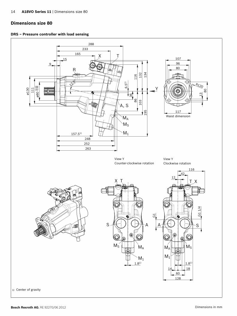
14 A18VO Series 11 | Dimensions size 80
Bosch Rexroth AG, RE 92270/06.2012 Dimensions in mm
Dimensions size 80
DRS – Pressure controller with load sensing
M1M1
MA MS
T X
SA
MAMS
TX
S A
MA
MS
M1
A, S
Y
TX
R9
15
165233
288
103
134
132
116
3686
195
6.51)
263
248252
157.51)
8096107
12.5°
-0.0
6-0
.03
ø80
117
8013
R120
1814
12860
1.81)1.81)
G1 G1
1/4
11642
12
ø130 11
1
View Y Clockwise rotation
View Y Counter-clockwise rotation
Waist dimension
1) Center of gravity
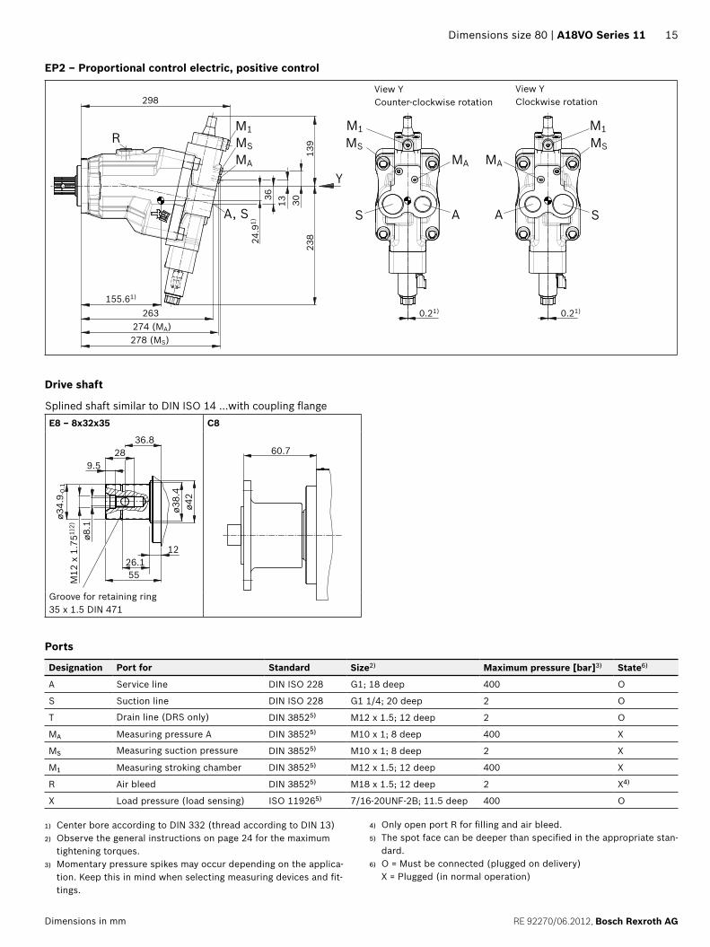
Dimensions size 80 | A18VO Series 11 15
RE 92270/06.2012, Bosch Rexroth AGDimensions in mm
EP2 – Proportional control electric, positive control
263 2
38
36
139
298
3013
155.61)
24.9
1)
278 (MS)274 (MA)
0.21) 0.21)
A, S
MA
A
MS
S
M1R
AS
MS
M1
MAMA
MS
M1
Y
View Y Clockwise rotation
View Y Counter-clockwise rotation
Drive shaft
Splined shaft similar to DIN ISO 14 ...with coupling flangeE8 ‒ 8x32x35 C8
9.5
55
28
12
36.8
26.1
M12
x 1
.751)
2)
ø34.
9 -0.
1
ø8.1
ø42
ø38.
4
60.7
Groove for retaining ring 35 x 1.5 DIN 471
Ports
Designation Port for Standard Size2) Maximum pressure [bar]3) State6)
A Service line DIN ISO 228 G1; 18 deep 400 O
S Suction line DIN ISO 228 G1 1/4; 20 deep 2 O
T Drain line (DRS only) DIN 38525) M12 x 1.5; 12 deep 2 O
MA Measuring pressure A DIN 38525) M10 x 1; 8 deep 400 X
MS Measuring suction pressure DIN 38525) M10 x 1; 8 deep 2 X
M1 Measuring stroking chamber DIN 38525) M12 x 1.5; 12 deep 400 X
R Air bleed DIN 38525) M18 x 1.5; 12 deep 2 X4)
X Load pressure (load sensing) ISO 119265) 7/16-20UNF-2B; 11.5 deep 400 O
1) Center bore according to DIN 332 (thread according to DIN 13)2) Observe the general instructions on page 24 for the maximum
tightening torques.3) Momentary pressure spikes may occur depending on the applica-
tion. Keep this in mind when selecting measuring devices and fit-tings.
4) Only open port R for filling and air bleed.5) The spot face can be deeper than specified in the appropriate stan-
dard.6) O = Must be connected (plugged on delivery)
X = Plugged (in normal operation)

16 A18VO Series 11 | Dimensions size 107
Bosch Rexroth AG, RE 92270/06.2012 Dimensions in mm
Dimensions size 107
DRS – Pressure controller with load sensing
915
179249
309
166.91)
282
252264
-0.0
6-0
.03
ø80
G1
1/4
19.514
13463
11642
12
108
141
137
126
4091
206
9.4
1)
12.5
°
8096107
124
8013
R120
1.41) 1.41)
ø140
111
TX
R
G1
SA
MA
MS
A, S
M1
T X
MA MS
M1
S A
TX
MAMS
M1
Y
View Y Clockwise rotation
View Y Counter-clockwise rotation
Waist dimension
1) Center of gravity

Dimensions size 107 | A18VO Series 11 17
RE 92270/06.2012, Bosch Rexroth AGDimensions in mm
EP2 – Proportional control electric, positive control
View Y Clockwise rotation
View Y Counter-clockwise rotation
249
40 3514
145
287 (MA)283 (MS)282 (A, S)
166.81)
319
26.5
1)
0.21)0.21)
R
A, S
MA
MS
M1
SA
MA
MS
M1MS
M1
S
MA
A
Y
EP6 – Proportional control electric, negative control
307
187
M1
MS
MA
SA
MA
MS
A, S
M11711)
7.51)
0.21)
Y
View Y Clockwise rotation

18 A18VO Series 11 | Dimensions size 107
Bosch Rexroth AG, RE 92270/06.2012 Dimensions in mm
Drive shaft
Splined shaft similar to DIN ISO 14 ...with coupling flangeE8 ‒ 8x32x35 C8
9.5
55
28
12
36.8
26.1
M12
x 1
.751)
2)
ø34.
9 -0.
1
ø8.1
ø42
ø38.
4
60.7
Groove for retaining ring 35 x 1.5 DIN 471
Ports
Designation Port for Standard Size2) Maximum pressure [bar]3) State6)
A Service line DIN ISO 228 G1; 18 deep 400 O
S Suction line DIN ISO 228 G1 1/4; 20 deep 2 O
T Drain line (DRS only) DIN 38525) M12 x 1.5; 12 deep 2 O
MA Measuring pressure A DIN 38525) M10 x 1; 8 deep 400 X
MS Measuring suction pressure DIN 38525) M10 x 1; 8 deep 2 X
M1 Measuring stroking chamber DIN 38525) M12 x 1.5; 12 deep 400 X
R Air bleed DIN 38525) M18 x 1.5; 12 deep 2 X4)
X Load pressure (load sensing) ISO 119265) 7/16-20UNF-2B; 11.5 deep 400 O
1) Center bore according to DIN 332 (thread according to DIN 13)2) Observe the general instructions on page 24 for the maximum
tightening torques.3) Momentary pressure spikes may occur depending on the applica-
tion. Keep this in mind when selecting measuring devices and fit-tings.
4) Only open port R for filling and air bleed.5) The spot face can be deeper than specified in the appropriate stan-
dard. 6) O = Must be connected (plugged on delivery)
X = Plugged (in normal operation)

Suction stud | A18VO Series 11 19
RE 92270/06.2012, Bosch Rexroth AGDimensions in mm
Suction stud
Dimensions
EF
SW
CA D B
SW
DB
CA
EF
G
DB
CA
EF
G
SW
H
KJ
H
KJ
J
H
K
Axial piston unit Suction stud
NG Port S Inner Version Material numberA B [in] B [mm] C D E F G SW H J K
55 G1 1 1/2 39 Straight R902600251 23.5 33.5 72 54 ‒ 41 301 44 63
55 G1 2 51 R902602028 26 44 82 64 ‒ 55 312 47 70
80 G1 1/4 2 51 R902600252 30 44 85 65 ‒ 55 335 51 76
107 354 55 79
107 G1 1/4 2 1/2 63 R902601630 31 54 82 64 ‒ 65 354 54 79
55 G1 1 1/2 39 45° R909831600 26 31 101 82 45 41 342 7 59
55 G1 2 51 R902602029 26 43 100 81 44 41 344 7 61
80 G1 1/4 2 51 R909831597 34 43 101 81 40 50 364 15 68
107 383 18 71
107 G1 1/4 2 1/2 63 R902601631 35 54 100 81 44 50 387 14 74
55 G1 1 1/2 39 90° R909831599 26 31 64 44 85 41 321 41 56
55 G1 2 51 R902602030 26 43 62 42 81 41 324 38 58
80 G1 1/4 2 51 R909831598 35 43 63 43 80 50 346 33 66
107 365 29 70

20 A18VO Series 11 | Coupling flange
Bosch Rexroth AG, RE 92270/06.2012 Dimensions in mm
Notes on suction line Keep as short and straight as possible, without bend Use a supporting ring for plastic hoses Use two hose clamps to protect the suction hose against
air suction Note pressure resistance of suction hose compared to
ambient pressure
Replacing sealsThe O-rings used as seals to prevent air from entering the suction line are to be replaced after every removal and new installation in order to guarantee complete sealing.
Material number for O-rings: R902083802: O-ring for suction stud G1 R902083808: O-ring for suction stud G1 1/4
Coupling flange
There are specially modified coupling flanges in 4-hole and 6-hole designs for the cardan-shaft drive.
4-hole coupling flange, complete – Ø90Material number: R902060152
ø90
ø47 -
0.02
5
2.3 6
48.2
42.5 ø8.5
ø74.5
Zylinderschraube DIN 912M12 x 35 - 10.9
0
6-hole coupling flange, complete – Ø100Material number: R902060153
ø99
2.3 7
48.2
42.5 ø8.5
ø84
Zylinderschraube DIN 912M12 x 35 - 10.9
ø57 -
0.04
60
NoteThe coupling flange is installed by screwing it onto the drive shaft with the help of the threaded bore in the end of the drive shaft.The coupling flange must be glued onto the splined drive shaft with Loctite 574 and clamped (= 130 Nm).Sudden or abrupt forces acting on the drive shaft could lead to damage to the rotary group and must therefor be avoided.
Socket-head screw DIN 912
Socket-head screw DIN 912

Connector for solenoids | A18VO Series 11 21
RE 92270/06.2012, Bosch Rexroth AG
Connector for solenoids
DEUTSCH DT04-2P-EP04Molded, 2-pin, without bidirectional suppressor diode There is the following type of protection with mounted mating connector:
IP67 (DIN/EN 60529) and IP69K (DIN 40050-9)
Circuit symbol
Mating connectorDEUTSCH DT06-2S-EP04 Bosch Rexroth Mat. No. R902601804
Consisting of: DT designation
1 housing DT06-2S-EP04
1 wedge W2S
2 sockets 0462-201-16141
The mating connector is not included in the delivery con-tents. This can be supplied by Bosch Rexroth on request.
ø37
68.550
36.7
(2)(1)
36.7
Changing connector orientationIf necessary, you can change the connector orientation by turning the solenoid housing.To do this, proceed as follows:
Loosen the mounting nut (1) of the solenoid. To do this, turn the mounting nut (1) one turn counter-clockwise.
Turn the solenoid body (2) to the desired orientation. Retighten the mounting nut. Tightening torque: 5+1 Nm.
(WAF26, 12-sided DIN 3124)On delivery, the connector orientation may differ from that shown in the brochure or drawing.

22 A18VO Series 11 | Installation instructions
Bosch Rexroth AG, RE 92270/06.2012
Installation instructions
GeneralDuring commissioning and operation, the axial piston unit must be filled with hydraulic fluid and air bled. This must also be observed following a relatively long standstill as the axial piston unit may drain back to the reservoir via the hydraulic lines. The case drain chamber is internally connected to the suction chamber. A case drain line from the case to the reservoir is not required. However, to ensure thermal stabil-ity, a case drain line from port "T" to the reservoir is gener-ally required with the DRS controller. To achieve favorable noise values, decouple all connecting lines using elastic elements and avoid above-reservoir installation. In all operating conditions, the suction and case drain lines must flow into the reservoir below the minimum fluid level. The permissible suction height hS results from the overall loss of pressure; it must not, however, be higher than hS max = 800 mm. The minimum suction pressure at port S must also not fall below 0.8 bar absolute during operation and during cold start.
Installation positionSee the following examples 1 to 4. Further installation positions are available upon request.Recommended installation position: 1 and 2.
Below-reservoir installation (standard)Below-reservoir installation means that the axial piston unit is installed outside of the reservoir below the minimum fluid level.
1 2
S
SB
TR
ht min
hminamin
S
MS
SB
T
amin
Installation position Air bleed Filling
1 R S
2 MS S
Above-reservoir installationAbove-reservoir installation means that the axial piston unit is installed above the minimum fluid level of the reservoir.Observe the maximum permissible suction height hS max = 800 mm.
3 4
S
SB
TR L
ht min
hmin
hS max
amin
SMS
SB
T
L
ht min
hmin
hS max
amin
Installation position Air bleed Filling
3 R L
4 MS L
Key
L Filling / air bleed
R Air bleed port
S Suction port
T Drain port (DRS only)
SB Baffle (baffle plate)
ht min Minimum required immersion depth (200 mm)
hmin Minimum required spacing to reservoir bottom (100 mm)
hS max Maximum permissible suction height (800 mm)
MS Measuring port suction pressure
amin When designing the reservoir, ensure adequate space be-tween the suction line and the case drain line. This pre-vents the heated, return flow from being drawn directly back into the suction line.

Other related documents | A18VO Series 11 23
RE 92270/06.2012, Bosch Rexroth AG
Other related documents
Other pumps with special characteristics and dimensions for use in commercial vehicles can be found in the following data sheets:
RE 91510: Fixed pump A17FNO, 250/300 bar RE 91520: Fixed pump A17FO, 300/350 bar RE 91540: 2-circuit fixed pump A18FDO, 350/400 bar RE 92260: Variable pump A17VO, 300/350 bar RE 92280: Variable pump A18VLO, 350/400 bar

24
Bosch Rexroth AG, RE 92270/06.2012
Bosch Rexroth AGMobile ApplicationsGlockeraustrasse 489275 Elchingen, GermanyTel.: +49 73 08 82-0Fax: +49 73 08 72 [email protected]/axial-piston-pumps
© This document, as well as the data, specifications and other information set forth in it, are the exclusive property of Bosch Rexroth AG. It may not be reproduced or given to third parties without its consent. The data specified above only serve to describe the product. No statements concerning a certain condition or suitability for a certain application can be derived from our information. The information given does not release the user from the obligation of own judgment and verification. It must be remembered that our products are subject to a natural process of wear and aging.
A18VO Series 11 | General instructions
General instructions
The pump A18VO is designed to be used in open cir-cuits.
The project planning, installation and commissioning of the axial piston unit requires the involvement of quali-fied personnel.
Before using the axial piston unit, please read the corre-sponding instruction manual completely and thoroughly. If necessary, these can be requested from Bosch Rexroth.
During and shortly after operation, there is a risk of burns on the axial piston unit and especially on the solenoids. Take appropriate safety measures (e. g. by wearing protective clothing).
Depending on the operating conditions of the axial piston unit (operating pressure, fluid temperature), the characteristic may shift.
Service line ports: – The ports and fastening threads are designed for the
specified maximum pressure. The machine or system manufacturer must ensure that the connecting ele-ments and lines correspond to the specified applica-tion conditions (pressure, flow, hydraulic fluid, tem-perature) with the necessary safety factors.
– The service line ports and function ports can only be used to accommodate hydraulic lines.
The data and notes contained herein must be adhered to.
Before finalizing your design, request a binding installa-tion drawing.
The product is not approved as a component for the safety concept of a general machine according to ISO 13849.
Pressure controls are not backups against pressure overload. A pressure-relief valve is to be provided in the hydraulic system.
The following tightening torques apply: – Fittings:
Observe the manufacturer's instructions regarding the tightening torques of the fittings used.
– Mounting bolts: For mounting bolts with metric ISO threads accord-ing to DIN 13, we recommend checking the tighten-ing torque in individual cases in accordance with VDI 2230.
– Female threads in the axial piston unit: The maximum permissible tightening torques MG max are maximum values of the female threads and must not be exceeded. For values, see the following table.
– Threaded plugs: For the metallic threaded plugs supplied with the axial piston unit, the required tightening torques of threaded plugs MV apply. For values, see the follow-ing table.
Ports Maximum permissible tightening torque of the female threads MG max
Required tightening torque of the threaded plugs MV
WAF Hexagon socket of the threaded plugsStandard Size of thread
DIN 38521) M10 x 1 30 Nm 15 Nm2) 5 mm
M12 x 1.5 50 Nm 25 Nm2) 6 mm
M18 x 1.5 66 Nm 60 Nm 8 mm
ISO 11926 7/16-20UNF-2B 40 Nm 15 Nm 3/16 in
DIN ISO 228 G3/4 330 Nm − −
G1 480 Nm − −
G1 1/4 720 Nm − −
1) The tightening torques are valid for the delivery condition "dry" and for the installation-related, "lightly oiled" condition of the screw.
2) In the "lightly oiled" condition, the MV is reduced to 10 Nm for M10 x 1 and to 17 Nm for M12 x 1.5.