Axial piston variable pump A10VO series 52 and 53 · Axial piston variable pump A10VO series 52 and...
72
RE-A 92703/12.2016, Bosch Rexroth AG A10VO 63DRS/53... Features ▶ Variable pump with axial piston rotary group in swash- plate design for hydrostatic drives in open circuit. ▶ The flow is proportional to the drive speed and the displacement. ▶ The flow can be infinitely varied by adjusting the swash- plate angle. ▶ Stable bearing for long service life ▶ High permissible drive speed ▶ Favorable power-to-weight ratio – compact dimensions ▶ Low noise ▶ Excellent suction characteristics ▶ Electro-hydraulic pressure control ▶ Power control ▶ Electro-proportional swivel angle control ▶ Short response times ▶ Sizes 10 to 100 ▶ Nominal pressure 3600 psi (250 bar) ▶ Maximum pressure 4550 psi (315 bar) ▶ Open circuit Axial piston variable pump A10VO series 52 and 53 RE-A 92703 Edition: 12.2016 Replaces: 03.2015 Inhalt Ordering code series 52/53 2 Hydraulic fluids 7 Operating pressure range 9 Technical data 10 DR – Pressure control 14 DRG – Pressure control, remotely operated 15 DRF (DFR) / DRS (DFR1) / DRSC– Pressure and flow control 16 LA... – Pressure, flow and power controller 18 LA... – Variations 19 ED – Electro-hydraulic pressure control 20 ER – Electro-hydraulic pressure control 21 EP – Electro-proportional control 22 EK – Electro-proportional control with controller cut-off 23 EP(K).DF / EP(K).DS / EP(K) – with pressure and flow control 24 EP.ED / EK.ED – with electro-hydraulic pressure control 25 Dimensions size 10 to 100 26 Dimensions through drive 61 Overview of attachment options 65 Combination pumps A10VO + A10VO 66 Connector for solenoids 67 Installation instructions 68 Project planning notes 72 Americas
Transcript of Axial piston variable pump A10VO series 52 and 53 · Axial piston variable pump A10VO series 52 and...

RE-A 92703/12.2016, Bosch Rexroth AG
A10VO 63DRS/53...
Features ▶ Variable pump with axial piston rotary group in swash-
plate design for hydrostatic drives in open circuit. ▶ The flow is proportional to the drive speed and the
displacement. ▶ The flow can be infinitely varied by adjusting the swash-
plate angle. ▶ Stable bearing for long service life ▶ High permissible drive speed ▶ Favorable power-to-weight ratio – compact dimensions ▶ Low noise ▶ Excellent suction characteristics ▶ Electro-hydraulic pressure control ▶ Power control ▶ Electro-proportional swivel angle control ▶ Short response times
▶ Sizes 10 to 100 ▶ Nominal pressure 3600 psi (250 bar) ▶ Maximum pressure 4550 psi (315 bar) ▶ Open circuit
Axial piston variable pumpA10VO series 52 and 53
RE-A 92703Edition: 12.2016Replaces: 03.2015
InhaltOrdering code series 52/53 2Hydraulic fluids 7Operating pressure range 9Technical data 10DR – Pressure control 14DRG – Pressure control, remotely operated 15DRF (DFR) / DRS (DFR1) / DRSC– Pressure and flow control 16LA... – Pressure, flow and power controller 18LA... – Variations 19ED – Electro-hydraulic pressure control 20ER – Electro-hydraulic pressure control 21EP – Electro-proportional control 22EK – Electro-proportional control with controller cut-off 23EP(K).DF / EP(K).DS / EP(K) – with pressure and flow control 24EP.ED / EK.ED – with electro-hydraulic pressure control 25Dimensions size 10 to 100 26Dimensions through drive 61Overview of attachment options 65Combination pumps A10VO + A10VO 66Connector for solenoids 67Installation instructions 68Project planning notes 72
Americas

Bosch Rexroth AG, RE-A 92703/12.2016
2 A10VO series 52 and 53 | Axial piston variable pumpOrdering code series 52
1) See data sheet 92709 for precise specification
Ordering code series 52
01 02 03 04 05 06 07 08 09 10 11 12
A10V(S) O / 52 – V
Axial piston unit 10 28 45 60 8501 Swashplate design, variable, nominal pressure 3600 psi (250 bar), ● – – – – A10VS
maximum pressure 4550 psi (315 bar) – ● ● ● ● A10V
Operation mode02 Pump, open circuit O
Size (NG)03 Geometric displacement, see table of values on page 10 10 28 45 60 85
Control devices04 Pressure control hydraulic ● ● ● ● ● DR
with flow controller hydraulic X-T open ● ● ● ● ● DFR
X-T plugged with flushing function ● ● ● ● ● DFR1
without flushing function – ● ● ● ● DRSC
with pressure cut-off hydraulic remotely operated ● ● ● ● ● DRG
electric negative control U = 12 V – ● ● ● ● ED71
U = 24 V – ● ● ● ● ED72
electric positive control U = 12 V – ● ● ● ● ER71
U = 24 V – ● ● ● ● ER72
Differential pressure control electric control (negative control) – ○ ○ ○ ● EF..1)
Series05 Series 5, Index 2 52
Direction of rotation06 View on drive shaft clockwise R
counter-clockwise L
Sealing material07 FKM (fluor-caoutchouc) V
Drive shaft08 splined shaft standard shaft ● ● ● ● ● S
ANSI B92.1a similar to shaft "S" however for higher input torque – ● ● ● ● R
reduced diameter, limited suitability for through drive ● ● ● ● ● U
similar to shaft "U", however for higher torque – ● ● ● ● W
Parallel keyed shaft ISO 3019-1 limited suitability for through drive ● ● ● ● ● K
Tapered with Woodruff key – ● ● ● ● C
Mounting flange09 ISO 3019-1 (SAE) 2-hole ● ● ● ● ● C
4-hole – – – ● – D
Note ▶ Observe the engineering notes regarding each
control device

RE-A 92703/12.2016, Bosch Rexroth AG
Axial piston variable pump | A10VO series 52 and 53 Ordering code series 52
3
01 02 03 04 05 06 07 08 09 10 11 12
A10V(S) O / 52 – V
Working port 10 28 45 60 8510 SAE flange port
UNC fastening threadrear not for through drive – ● ● ● ● 61
at side, opposite for through drive – ● ● ● ● 62
ISO threaded port rear not for through drive ● – – – – 64
Through drive (for attachment options, see page 62)
11 Flange ISO 3019-1 Hub for splined shaft2)
Diameter Diameter
without through drive ● ● ● ● ● N00
82-2 (A) 5/8 in 9T 16/32DP – ● ● ● ● K01
3/4 in 11T 16/32DP – ● ● ● ● K52
101-2 (B) 7/8 in 13T 16/32DP – ● ● ● ● K68
1 in 15T 16/32DP – – ● ● ● K04
127-4 (C) 1 1/4 in 14T 12/24DP – – – ● ● K15
1 1/2 in 17T 12/24DP – – – – ● K16
127-2 (C) 1 1/4 in 14T12/24DP – – – – ● K07
1 1/2 in 17T 12/24DP – – – – ● K24
Connector for solenoids12 Without connector (without solenoid, with hydraulic control only, without code) ● ● ● ● ●
DEUTSCH – molded connector, 2-pin – without suppressor diode (for electric controls) – ● ● ● ● P
● = Available ○ = On request – = Not available
Note ▶ Note the project planning notes on page 68. ▶ In addition to the ordering code, please specify the
relevant technical data when placing your order.
2) According to ANSI B92.1a

Bosch Rexroth AG, RE-A 92703/12.2016
4 A10VO series 52 and 53 | Axial piston variable pumpOrdering code series 53
1) See data sheet 92709 for precise specification
Ordering code series 53
01 02 03 04 05 06 07 08 09 10 11 12
A10V(S) O / 53 – V
Axial piston unit 18 28 45 63 72 85 10001 Swashplate design, variable, nominal pressure 3600 psi (250 bar), maximum pressure 4550 psi
(315 bar)● ● ● ● ● ● ● A10V
Operation mode02 Pump, open circuit O
Size (NG)03 Geometric displacement, see table of values on page 10 18 28 45 63 72 85 100
Control devices04 Pressure control hydraulic ● ● ● ● ● ● ● DR
X-T open ● – – ● ● ● ● DRF
X-T plugged with flushing function ● – – ● ● ● ● DRS
without flushing function ● ● ● ● ● ● ● DRSC
with pressure cut-off hydraulic remotely operated ● ● ● ● ● ● ● DRG
electric negative control U = 12 V ● ● ● ● ● ● ● ED71
U = 24 V ● ● ● ● ● ● ● ED72
electric positive control U = 12 V ● ● ● ● ● ● ● ER71
U = 24 V ● ● ● ● ● ● ● ER72
Differential pressure control electric control (negative control) ○ ○ ○ ○ ○ ● ● EF.1)
Power control with pres-sure cut-off
hydraulic start of control from 145 to 510 psi(10 to 35 bar)
● ● ● ● ● ● ● LA5D
520 to 1015(36 to 70 bar)
● ● ● ● ● ● ● LA6D
1030 to 1520 psi(71 to 105 bar)
● ● ● ● ● ● ● LA7D
1535 to 2030 psi(106 to 140 bar)
● ● ● ● ● ● ● LA8D
2045 to 3335 psi(141 to 230 bar)
● ● ● ● ● ● ● LA9D
remotely operated hydraulic start of control see LA.D ● ● ● ● ● ● ● LA.DG
flow control, X-T plugged
hydraulic start of control see LA.D ● ● ● ● ● ● ● LA.DS
electrically overridable (negative control)
start of control see LA.D
● ● ● ● ● ● ● LA.S
Note ▶ Observe the engineering notes regarding each
control device
RE-A 92703/12.2016, Bosch Rexroth AG
Axial piston variable pump | A10VO series 52 and 53 Ordering code series 53
5
18 28 45 63 72 85 10004 Electro-proportional control positive control
with pressure control U = 12 V ● ● ● ● ● ● ● EP1D
U = 24 V ● ● ● ● ● ● ● EP2D
with pressure and flow control (load sensing)
X-T open U = 12 V ● ● ● ● ● ● ● EP1DF
U = 24 V ● ● ● ● ● ● ● EP2DF
with pressure and flow control (load sensing)
X-T plugged U = 12 V ● ● ● ● ● ● ● EP1DS
U = 24 V ● ● ● ● ● ● ● EP2DS
with electro-hydraulic pressure control
U = 12 V ● ● ● ● ● ● ● EP1ED
U = 24 V ● ● ● ● ● ● ● EP2ED
Electro-proportional control positive control
with pressure control U = 12 V ● ● ● ● ● ● ● EK1D
U = 24 V ● ● ● ● ● ● ● EK2D
Pressure and flow control with controller cut-off (load sensing)
X-T open U = 12 V ● ● ● ● ● ● ● EK1DF
U = 24 V ● ● ● ● ● ● ● EK2DF
Pressure and flow control with controller cut-off (load sensing)
X-T plugged U = 12 V ● ● ● ● ● ● ● EK1DS
U = 24 V ● ● ● ● ● ● ● EK2DS
Electro-hydraulic pressure control with controller cut-off
U = 12 V ● ● ● ● ● ● ● EK1ED
U = 24 V ● ● ● ● ● ● ● EK2ED
Series05 Series 5, index 3 53
Direction of rotation06 View on drive shaft clockwise R
counter clockwise L
Sealing material07 FKM (fluor-caoutchouc) V
Drive shaft08 Splined shaft standard shaft ● ● ● ● ● ● ● S
ANSI B92.1a similar to shaft “S” however for higher input torque ● ● ● ● ● ● – R
reduced diameter, limited suitability for through drive ● ● ● ● ● ● ● U
similar to shaft “U”, however for higher torque – ● ● ● ● ● ● W
Parallel keyed shaft ISO 3019-1 limited suitability for through drive ● ● ● ● ● ● ● K
Mounting flange09 ISO 3019-1 (SAE) 2-hole ● ● ● ● ● ● ● C
4-hole – – – ● ● ● ● D
Note ▶ Note the project planning notes on page 68. ▶ In addition to the ordering code, please specify the
relevant technical data when placing your order.
01 02 03 04 05 06 07 08 09 10 11 12
A10V(S) O / 53 – V

Bosch Rexroth AG, RE-A 92703/12.2016
6 A10VO series 52 and 53 | Axial piston variable pumpOrdering code series 53
01 02 03 04 05 06 07 08 09 10 11 12
A10V(S) O / 53 – V
2) According to ANSI B92.1a
Working port 18 28 45 63 72 85 10010 SAE flange port
UNC fastening threadrear not for through drive ● ● ● ● ● ● ● 61
at side, opposite for through drive ● ● ● ● ● ● ● 62
Through drive (for attachment options, see page 62)
11 Flange ISO 3019-1 Hub for splined shaft2)
Diameter Diameter 18 28 45 63 72 85 100without through drive ● ● ● ● ● ● ● N00
82-2 (A) 5/8 in 9T 16/32DP ● ● ● ● ● ● ● K01
3/4 in 11T 16/32DP ● ● ● ● ● ● ● K52
101-2 (B) 7/8 in 13T 16/32DP – ● ● ● ● ● ● K68
1 in 15T 16/32DP – – ● ● ● ● ● K04
127-4 (C) 1 1/4 in 14T 12/24DP – – – ● ● ● ● K15
1 1/2 in 17T 12/24DP – – – – – ● ● K16
127-2 (C) 1 1/4 in 14T12/24DP – – – – – ● ● K07
1 1/2 in 17T 12/24DP – – – – ● ● K24
Connector for solenoids12 Without connector (without solenoid, with hydraulic control only, without code) ● ● ● ● ● ● ●
DEUTSCH – molded connector, 2-pin – without suppressor diode (for electric controls) ● ● ● ● ● ● ● P
● = Available ○ = On request – = Not available
Note ▶ Note the project planning notes on page 68. ▶ In addition to the ordering code, please specify the
relevant technical data when placing your order.

RE-A 92703/12.2016, Bosch Rexroth AG
Axial piston variable pump | A10VO series 52 and 53 Hydraulic fluids
7
Hydraulic fluids
The A10VO variable pump is designed for operation with HLP mineral oil according to DIN 51524. Application instructions and requirements for hydraulic fluids should be taken from the following data sheets before the start of project planning:
▶ 90220: Hydraulic fluids based on mineral oils and related hydrocarbons
▶ 90221: Environmentally acceptable hydraulic fluids
Notes on selection of hydraulic fluidThe hydraulic fluid should be selected such that the operat-ing viscosity in the operating temperature range is within the optimum range (νopt see selection diagram).
NoteAt no point of the component may the temperature be higher than 239 °F (115 °C). The temperature difference specified in the table is to be taken into account when determining the viscosity in the bearing.If the above conditions cannot be maintained due to extreme operating parameters, please contact the respon-sible member of staff at Bosch Rexroth.
Viscosity and temperature of hydraulic fluids
Viscosity Temperature Comment
Cold start νmax ≤ 7500 SUS(1600 mm2/s)
θSt ≥ -40 °F (-40 °C) t ≤ 1 min, without load (p ≤ 435 psi (30 bar)), n ≤ 1000 rpm
Permissible temperature difference ΔT ≤ 45 °F (25 K) between axial piston unit and hydraulic fluid
Warm-up phase ν < 7500 to 1850 SUS (1600 to 400 mm2/s)
θ = -40 °F to -13 °F(-40 °C to -25 °C)
Note the detailed information on operation with low tempera-tures, see data sheet 90300-03-B.
Continuous operation ν = 1850 to 60 SUS(400 to 10 mm2/s)
This corresponds, for example on the VG 46, to a temperature range of 41 °F (+5 °C) to 185 °F (+85 °C) (see selection dia-gram page 5)
θ = -13 °F to +230 °F(-25 °C to +110 °C)
measured at port LNote the permissible temperature range of the shaft seal(ΔT = approx. 9 °F (5 K) between the bearing/shaft seal and port L)
νopt = 170 to 80 SUS(36 to 16 mm2/s)
Range of optimum operating viscosity and efficiency
Short-term operation νmin ≥ 49 SUS (7 mm2/s) t < 1 min, p < 0.3 • pnom
▼ Selection diagram
Range of optimum operating viscosity vopt
Optimum efficiency
Maximum permissible viscosity for cold start
Minimum permissible viscosity for short-term operation
Temperature θ [°C]
Visc
osity
ν [
mm
2 /s]
Con
tinuo
us o
pera
tion
Warm-up phase
Minimum permissible temperature for cold start
-40 -13 -14 50 86 122 194 23915832-40 -25 -10 10 30 50 90 115
[°F][°C]700
7
10
4060
20
100
200
400600
10001600
VG 22VG 32VG 46VG 68VG 100
16
36
20
60
200300
100
500
1000
2000300046001600
[mm2/s] [SUS]
74
170

Bosch Rexroth AG, RE-A 92703/12.2016
8 A10VO series 52 and 53 | Axial piston variable pumpHydraulic fluids
Filtration of the hydraulic fluidFiner filtration improves the cleanliness level of the hydraulic fluid, which increases the service life of the axial piston unit. A cleanliness level of at least 20/18/15 is to be maintained according to ISO 4406.At very high hydraulic fluid temperatures (194 °F (90 °C) to maximum 239 °F (115 °C)), cleanliness level 19/17/14 according to at least ISO 4406 is necessary. Please contact us if the above classes cannot be observed.

RE-A 92703/12.2016, Bosch Rexroth AG
Axial piston variable pump | A10VO series 52 and 53 Operating pressure range
9
Operating pressure range
Pressure at working port B Definition
Nominal pressure pnom 3600 psi (250 bar) absolute The nominal pressure corresponds to the maximum design pressure.
Maximum pressure pmax 4550 psi (315 bar) absolute The maximum pressure corresponds the maximum operating pressure within the single operating period. The sum of the single operating periods must not exceed the total operating period.
Single operating period 2.5 ms
Total operating period 300 h
Minimum pressure pB abs
(high pressure side)145 psi (10 bar) absolute Minimum pressure on the high-pressure side (B) which is required in or-
der to prevent damage to the axial piston unit.
Rate of pressure change RA max 232000 psi/s (16000 bar/s) Maximum permissible rate of pressure build-up and pressure reduction during a pressure change over the entire pressure range.
Pressure at suction port S (Inlet)
Minimum pressure pS min Standard 12 psi (0.8 bar) absolute Minimum pressure at suction port S (inlet) that is required in order to avoid damage to the axial piston unit. The minimum pressure depends on the speed and displacement of the axial piston unit.
Maximum pressure pS max 75 psi (5 bar) absolute
Case drain pressure at port L1, L2
Maximum pressure pL max 30 psi (2 bar) absolute Maximum 7.5 psi (0.5 bar) higher than inlet pressure at port S, but not higher than pL max. A case drain line to the reservoir is required.
▼ Rate of pressure change RA max
pnom
∆t
∆p
Time t
Pres
sure
p
▼ Maximum permissible speed (limit speed) Permissible speed by increasing inlet pressure pabs at suction opening S or at Vg ≤ Vgmax
1.00.90.80.7
1.2
1.1
1.0
0.9
24
20
17
15
13
12
(1.6)
(1.4)
(1.2)
(1.0)
(0.9)
(0.8)
Displacement Vg/Vgmax
Spee
d n/
n max
Inle
t pr
essu
re p
abs p
si (
bar)
▼ Pressure definition
Pres
sure
p
t1
t2tnSingle operating period
Minimum pressure (high-pressure side)
Maximum pressure pmax
Nominal pressure pnom
Time t
Total operating period = t1 + t2 + ... + tn
NoteOperating pressure range valid when using hydraulic fluids based on mineral oils. Please contact us for values for other hydraulic fluids.

Bosch Rexroth AG, RE-A 92703/12.2016
10 A10VO series 52 and 53 | Axial piston variable pumpTechnical data
Technical data
Size NG 101) 182) 28 45 601) 632) 722) 85 1002)
Displacement, geometric, per revolution
Vg max in3
(cm3)0.64(10.5)
1.10(18)
1.75(28)
2.75(45)
3.66(60)
3.84(63)
4.39(72)
5.18(85)
6.10(100)
Maximum rotational speed3)
at Vg max nnom rpm 3600 3300 3000 26004) 2700 2600 2600 2500 2300
at Vg <Vg max nmax
perm
rpm 4320 3960 3600 3120 3140 3140 3140 3000 2500
Flow at nnom and Vg
max
qv gpm(l/min)
9.7(37)
15.6(59)
22(84)
31(117)
42(162)
43(163)
49.4(187)
55(212)
60(230)
at nE = 1500 rpm qvE gpm(l/min)
4(15)
7.1(27)
1.1(42)
18(68)
24(90)
25.1(95)
28.5(108)
34(128)
39(150)
Power at nnom, Vg max and Δp =3600 psi (250 bar)
P HP(kW)
22(16)
34(25)
47(35)
65(49)
88(65)
90(68)
103(77)
119(89)
130(96)
at nE = 1500 rpm PE HP(kW)
9.4(7)
15(11)
24(18)
38(28)
50(37)
52(39)
60(45)
71(53)
84(62)
Torque at Vg max and Δp = 3600 psi (250 bar)
T lb-ft(Nm)
31(42)
52(71)
82(111)
132(179)
175(238)
184(250)
211(286)
247(338)
293(398)
at Vg max and Δp = 1440 psi (100 bar)
T lb-ft(Nm)
13(17)
21(29)
33(45)
53(72)
70(95)
74(100)
84(114)
102(135)
117(159)
Rotary stiffness of drive shaft
S c lb-ft/rad(Nm/rad)
6760(9200)
8082(11000)
16400(22300)
27560(37500)
48100(65500)
48100(65500)
48100(65500)
105100(143000)
105100(143000)
R c lb-ft/rad(Nm/rad)
–(–)
10870(14800)
19400(26300)
30240(41000)
51200(69400)
51200(69400)
51200(69400)
112773(152900)
–(–)
U c lb-ft/rad(Nm/rad)
5020(6800)
5870(8000)
12317(16700)
22130(30000)
36290(49200)
36290(49200)
36290(49200)
75900(102900)
75900(102900)
W c lb-ft/rad(Nm/rad)
–(–)
–(–)
14678(19900)
25370(34400)
39830(54000)
39830(54000)
39830(54000)
86960(117900)
86960(117900)
K c lb-ft/rad(Nm/rad)
7965(10800)
9810(13300)
19770(26800)
32380(43900)
54506(73900)
54506(73900)
54506(73900)
120518(163400)
120518(163400)
C c lb-ft/rad(Nm/rad)
–(–)
–(–)
6) 6) 6) –(–)
–(–)
6) –(–)
Moment of inertia for rotary group
JTW lbs-ft2
(kgm2)0.0142(0.0006)
0.2207(0.0009)
0.0403(0.0017)
0.0783(0.003)
0.1329(0.0056)
0.1329(0.0056)
0.1329(0.0056)
0.2848(0.012)
0.2848(0.012)
Maximum angular accelera-tion5)
α rad/s² 8000 6800 5500 4000 3300 3300 3300 2700 2700
Case vol-ume
V gal(L)
0.05(0.2)
0.06(0.25)
0.08(0.3)
0.13(0.5)
0.21(0.8)
0.21(0.8)
0.21(0.8)
0.26(1)
0.26(1)
Weight without through drive (approx.)
m lbs(kg)
17(8)
25(11.5)
33(15)
40(18)
48.5(22)
48.5(22)
48.5(22)
79(36)
79(36)
Weight with through drive (approx.)
lbs(kg)
–(–)
28.6(13)
40(18)
53(24)
62(28)
62(28)
62(28)
99(45)
99(45)
1) Only series 522) Only series 533) The values are applicable:
‒ At absolute pressure pabs = 15 psi (1 bar) at suction port S ‒ For the optimal viscosity range of νopt = 170 to 80 SUS (36 to 16 mm2/s) ‒ For hydraulic fluid based on mineral oils
4) Please contact us regarding higher speeds
5) The scope of application lies between the minimum necessary and the maximum permissible drive speeds. It applies for external stim-uli (e. g. engine 2 to 8 times rotary frequency, cardan shaft twice the rotary frequency). The limiting value is only valid for a single pump. The loading capacity of the connecting parts must be taken into account.
6) On request

RE-A 92703/12.2016, Bosch Rexroth AG
Axial piston variable pump | A10VO series 52 and 53 Technical data
11
Determining the operating characteristics
Flow qv =Vg × n × ηv [gpm
(l/min)]231 (1000)
Torque T = Vg × Δp [lb-ft
(Nm)]24 (20) × π × ηmh
Power P =2 π × T × n
=qv × Δp [HP
(kW)]33000 (60000) 1714 (600) × ηt
Key
Vg = Displacement per revolution [in3 (cm3)]
Δp = Differential pressure [psi (bar)]
n = Rotational speed [rpm]
ηv = Volumetric efficiency
ηmh = Mechanical-hydraulic efficiency
ηt = Total efficiency (ηt = ηv × ηmh)
Note ▶ Theoretical values, without efficiency and tolerances;
values rounded. ▶ Operation above the maximum values or below the
minimum values may result in a loss of function, a reduced service life or in the destruction of the axial piston unit. Bosch Rexroth recommend testing the loads by means of experiment or calculation / simula-tion and comparison with the permissible values.

Bosch Rexroth AG, RE-A 92703/12.2016
12 A10VO series 52 and 53 | Axial piston variable pumpTechnical data
Permissible radial and axial forces on the drive shaft
Size NG 10 18 28 45 60/63 72 85 100
Radial force maximum at a/2 Fq
a
a/2 a/2
± Fq max lbf(N)
56(250)
78(350)
270(1200)
337(1500)
382(1700)
337(1500)
450(2000)
450(2000)
Axial force maximum± Fax
+ Fax max lbf(N)
90(400)
157(700)
225(1000)
337(1500)
450(2000)
337(1500)
675(3000)
675(3000)
Note ▶ The values given are maximum values and do not apply
to continuous operation. For drives with radial loading (pinion, V-belt drives), please contact us!
Permissible input and through-drive torques
Size 10 18 28 45 60/63 72 85 100
Torque at Vg max and Δp = 3600 psi (250 bar)1) T max lbft(Nm)
31(42)
52(71)
82(111)
132(179)
184(250)
211(286)
247(338)
293(398)
Input torque at drive shaft, maximum2)
S TE max lb-ft(Nm)
93(126)
91(124)
146(198)
235(319)
464(630)
464(630)
853(1157)
814(1104)
DIA in 3/4 3/4 7/8 1 1 1/4 1 1/4 1 1/2 1 1/2
R TE max lb-ft(Nm)
–(–)
118(160)
184(250)
295(400)
479(650)
479(650)
895(1215)
–
DIA in – 3/4 7/8 1 1 1/4 1 1/4 1 1/2 –
U TE max lb-ft(Nm)
44(60)
43(59)
77(105)
139(188)
226(306)
226(306)
463(628)
438(595)
DIA in 5/8 5/8 3/4 7/8 1 1 1 1/4 1 1/4
W TE max lb-ft(Nm)
–(–)
–(–)
103(140)
162(220)
292(396)
282(383)
479(650)
469(636)
DIA in – – 3/4 7/8 1 1 1 1/4 1 1/4
K TE max lb-ft(Nm)
78(106)
76(104)
107(145)
156(212)
325(441)
325(441)
553(750)
553(750)
DIA in 3/4 3/4 7/8 1.000 1 1/4 1 1/4 1 1/2 1 1/2
C TE max lb-ft(Nm)
–(–)
–(–)
107(145)
156(212)
325(441)
–(–)
553(750)
–(–)
Maximum through-drive torque
S TD max lb-ft(Nm)
–(–)
80(108)
118(160)
235(319)
357(484)
357(484)
515(698)
573(778)
R TD max lb-ft(Nm)
–(–)
89(120)
130(176)
270(365)
357(484)
357(484)
515(698)
–(–)
U TD max lb-ft(Nm)
–(–)
43(59)
77(105)
139(188)
226(306)
226(306)
463(628)
438(595)
W TD max lb-ft(Nm)
–(–)
–(–)
103(140)
162(220)
292(396)
282(383)
479(650)
469(636)
K TD max lb-ft(Nm)
–(–)
76(104)
107(145)
156(212)
325(441)
325(441)
–(–)
553(750)
1) Without considering efficiency2) For drive shafts with no radial force3) only size 60

RE-A 92703/12.2016, Bosch Rexroth AG
Axial piston variable pump | A10VO series 52 and 53 Technical data
13
▼ Distribution of torques
TE
TD
T1 T2
T31st pump 2nd pump
Torque at 1st pump T1
Torque at 2nd pump T2
Torque at 3rd pump T3
Input torque TE = T1 + T2 + T3
TE < TE max
Through-drive torque TD = T2 + T3 TD < TD max

Bosch Rexroth AG, RE-A 92703/12.2016
14 A10VO series 52 and 53 | Axial piston variable pumpDR – Pressure control
DR – Pressure control
The pressure control limits the maximum pressure at the pump outlet within the control range of the variable pump. The variable pump only supplies as much hydraulic fluid as is required by the consumers. If the operating pressure exceeds the pressure setting at the pressure valve, the pump will regulate to a smaller displacement to reduce the control differential.
▶ Basic position in depressurized state:Vg max. ▶ Setting range1) for pressure control 510 to 3600 psi
(35 to 250 bar). Standard is 3600 psi (250 bar).
▼ Characteristic curve DR
3600
qv min qv max
250[psi][bar]
Standby 2)
Ope
ratin
g pr
essu
re p
B
Flow qV
Hys
tere
sis/
pres
sure
ris
e Δp
max
Characteristic curve valid for n1 = 1500 rpm and tfluid = 120 °F (50 °C).
▼ Circuit diagram DR
SL2
BL1L
Controller data
NG 10 18 28 45 6063
72 85 100
Pressure increase
Δp [psi][bar]
87 (6)
87(6)
87(6)
87(6)
115(8)
115(8)
175(12)
200(14)
Hysteresis and re-peatability
Δp [psi (bar)]
maximum 45 (3)
Control fluid con-sumption
gpm(l/min)
maximum approx. 0.8 (3)
1) In order to prevent damage to the pump and the system, the per-missible setting range must not be exceeded. The range of possi-ble settings at the valve is higher.

RE-A 92703/12.2016, Bosch Rexroth AG
Axial piston variable pump | A10VO series 52 and 53 DRG – Pressure control, remotely operated
15
DRG – Pressure control, remotely operated
For the remote-controlled pressure control, the LS pressure limitation is performed using a separately arranged pres-sure relief valve. Therefore any pressure control value under the pressure set on the pressure controller can be regu-lated. Pressure controller DR see page 14.A pressure relief valve is externally piped to port X for remote setting of pressure below the setting of the DR control valve spool. This relief valve is not included in the scope of delivery of the DRG control.When there is differential pressure Δp at the control valve and with the standard setting on the remote-controlled pressure cut-off of 290 psi (20 bar), the amount of control fluid at the connection is X approx. 0.4 gpm (1.5 l/min). If a different setting (range from 145 to 320 psi (10 to 22 bar)) is required, please state in plain text.As a separate pressure relief valve (1) we recommend:
▶ a directly controlled, hydraulic or electric proportional one, suitable for the control fluid mentioned above.
The max. length of piping should not exceed 6.6 ft (2 m). ▶ Basic position in depressurized state:Vg max. ▶ Setting range1) for pressure control 501 to 3600 psi(35
to 250 bar) (3). Standard is 3600 psi (250 bar).
▶ Setting range for differential pressure 145 to 320 psi (10 to 22 bar) (2) Standard is 290 psi (20 bar).
Unloading port X to the reservoir results in a zero stroke (standby) pressure which is approx. 15 to 30 psi (1 to 2 bar) higher than the defined differential pressure ∆p, however system influences are not taken into account.
▼ Characteristic curve DRG
3600
qv min qv max
250[psi][bar]
Standby 2)
Ope
ratin
g pr
essu
re p
B
Flow qV
Hys
tere
sis/
pres
sure
ris
e Δp
max
Characteristic curve valid for n1 = 1500 rpm and tfluid = 120 °F (50 °C).
▼ Circuit diagram DRG
SL2
BL
X
L1
1
3
2
1 The separate pressure relief valve and the line are not included in the scope of delivery.
2 Remote-controlled pressure cut-off (G).3 Pressure controller (DR)Controller data
NG 10 18 28 45 6063
72 85 100
Pressure increase
Δp [psi][bar]
87 (6)
87(6)
87(6)
87(6)
115(8)
115(8)
175(12)
200(14)
Hysteresis and re-peatability
Δp [psi (bar)]
maximum 45 (3)
Control fluid con-sumption
gpm(l/min)
maximum approx. 1.2 (4.5)
1) In order to prevent damage to the pump and the system, the per-missible setting range must not be exceeded. The range of possi-ble settings at the valve is higher.
2) Zero stroke from pressure setting Δ p on controller (2)

Bosch Rexroth AG, RE-A 92703/12.2016
16 A10VO series 52 and 53 | Axial piston variable pumpDRF (DFR) / DRS (DFR1) / DRSC– Pressure and flow control
DRF (DFR) / DRS (DFR1) / DRSC– Pressure and flow control
In addition to the pressure controller function (see page 14), a variable orifice (e.g. directional valve) is used to adjust the differential pressure upstream and downstream of the orifice. This is used to control the pump flow. The pump flow is equal to the actual hydraulic fluid quantity required by the consumer. With all controller combinations, the Vg reduction has priority.
▶ Basic position in depressurized state:Vg max. ▶ Setting range1) to 3600 psi (250 bar). ▶ DR pressure controller data see page 14
▼ Characteristic curve DRF (DFR) / DRS (DFR1) / DRSC
3600
qv min qv max
250[psi][bar]
Standby2)
Ope
ratin
g pr
essu
re p
B
Flow qV
Hys
tere
sis/
pres
sure
ris
e Δp
max
▼ Characteristic curve at variable speed
qV max
qV min
n0
n maxRotational speed n
Flow
qV
Hys
tere
sis/
Pres
sure
incr
ease
Δq V
max
Characteristic curves valid for n1 = 1500 rpm and tfluid = 120 °F (50 °C).
Possible connections at port B (not included in the delivery contents)
LS mobile control blocks Data sheets
M4-12 64276
M4-15 64283
LUDV mobile control blocks
M6-15 64284
M7-22 64295
▼ Circuit diagram DRF (DFR)
SL2
BL
X
1
L1
2
3
Plugged at DRS (DFR1) / DRSC valve
1 The metering orifice (control block) and the line is not included in the delivery contents.
2 Pressure and flow controller (FR).3 Pressure controller (DR)
Note The DRS and (DFR1) and DRSC valve versions have no pilot line between X and the reservoir. Unloading the LS-pilot line must be possible in the valve system.Because of the flushing function sufficient unloading of the flow control in DRS (DFR1) control valve X-line must also be provided.If this pilot line of the X line does not have to be guaran-teed, the DRSC control valve must be used.
For further information see page 17
1) In order to prevent damage to the pump and the system, the per-missible setting range must not be exceeded. The range of possi-ble settings at the valve is higher.
2) Zero stroke from differential pressure setting Δp on controller (2)

RE-A 92703/12.2016, Bosch Rexroth AG
Axial piston variable pump | A10VO series 52 and 53 DRF (DFR) / DRS (DFR1) / DRSC– Pressure and flow control
17
Differential pressure ∆p: ▶ Standard setting: 200 psi (14 bar)
If another setting is required, please state in clear text. ▶ Adjustment range: 200 to 320 psi (14 to 22 bar)
Unloading port X to the reservoir results in a zero stroke (standby) pressure which is approx. 15 to 30 psi (1 to 2 bar) higher than the defined differential pressure ∆p, however system influences are not taken into account.
Controller data ▶ DR pressure controller data see page 14. ▶ Maximum flow deviation measured at drive speed
n = 1500 rpm.
NG 10 18 28 45 60 63
72 85 100
Flow deviation Δq vmax [gpm (l/min)] 0.13 (0.5) 0.24 (0.9) 0.26 (1.0) 0.48 (1.8) 0.66 (2.5) 0.66 (2.5) 0.83 (3.1) 0.83 (3.1)
Hysteresis and repeatability
Δp [psi (bar)] maximum 45 (3)
Control fluid consumption
gpm (gpm (l/min)) maximum approx. 0.8 to 1.2 (3 to 4.5) (DRF (DFR)) maximum approx. 0.8 (3) (DRS (DFR1) / DRSC)

Bosch Rexroth AG, RE-A 92703/12.2016
18 A10VO series 52 and 53 | Axial piston variable pumpLA... – Pressure, flow and power controller
LA... – Pressure, flow and power controller
Pressure control equipped as DR(G), see page 14 (15). Equipment of the flow control like DRS (DFR1), see page 16.In order to achieve a constant drive torque with varying operating pressures, the swivel angle and with it the vol-ume flow from the axial piston pump is varied so that the product of flow and pressure remains constant. Flow con-troller is possible below the power control curve. When
ordering please state the power characteristics to be set ex works in clear text, e.g. 27 HP (20 kW) at 1500 rpm.Controller data
▶ Pressure controller DR see page 14. ▶ Pressure and flow controller DR see page 16. ▶ See data sheet 92709 for electric override LA.S ▶ Control fluid consumption max. approx. 1.45 gpm (5.5 l/
min)
Start of control Torque T [lb-ft (Nm)] for nominal size Ordercodepsi (bar) 18 28 45 63 72 85 100
145 to 510(10 to 35)
2.80 – 8.92(3.8 – 12.1)
4.4 – 14(6 – 19)
7.4 – 22.1(10 – 30)
11 – 32(15 – 43)
12.5 – 36.3(17 – 49.2)
15 – 42(20 – 57)
18 – 49.5(24 – 68)
LA5
520 to 1015(36 to 70)
8.92 – 17.2(12.2 – 23.3)
14 – 26.5(19.1 – 36)
22.2 – 43.5(30.1 – 59)
32 – 61(43.1 – 83)
36.4 – 69.9(49.3 – 94.9)
42 – 83(57.1 – 112)
49.5 – 97.1(68.1 – 132)
LA6
1030 to 1520(71 to 105)
17.2 –24.9(23.4 – 33.7)
26.6 – 38.4(36.1 – 52)
43.6 – 62(59.1 – 84)
61 – 88(83.1 – 119)
70 – 100.3(95.0 – 136.0)
83 – 118(112.1 – 160)
97.1 – 139.4(132.1 – 189)
LA7
1535 to 2030(106 to 140)
24.9 –33.2(33.8 – 45)
38.4 – 51.6(52.1 – 70)
62 – 83(84.1 – 112)
88 – 116(119.1 – 157)
100.4 – 132.3(136.1 – 179.4)
118 – 156(160.1 – 212)
139.4 – 183.6(189.1 – 249)
LA8
2045 to 3335(141 – 230)
33.2 – 55.2(45.1 – 74.8)
51.7 – 86.3(70.1 – 117)
83 – 139(112.1 – 189)
116 – 195(157.1 – 264)
132.4 – 222.5(179.5 – 301.7)
156 – 263(212.1 – 357)
183.3 – 309(249.1 – 419)
LA9
Conversion of the torque values in power [HP kW]
P=T
[HP (kW)] (at 1500 rpm) or P=2 x T x n
[HP (kW)] (rotational speeds, see table on page 10)3.5 (6.4) 33000 (60000)
▼ Characteristic curve LA.DS
0 100
0
725
1450
2200
2900
3600
4350
0
50
100
150
200
250
300[psi][bar]
0 100
∆qV
LA9
LA8
LA7
LA5LA6
LA9
LA8
LA7
LA5
LA6
Volume flow qV [%]
Ope
ratin
g pr
essu
re p
B
Torq
ue T
[lb-
ft (
Nm
)]
Volume flow qV [%]
▼ Circuit diagram LA.DS (for further combination options with LA.. see page 19)
SL2
BL
X X
L1
1
1 The metering orifice (control block) and the line is not included in the delivery contents.

RE-A 92703/12.2016, Bosch Rexroth AG
Axial piston variable pump | A10VO series 52 and 53 LA... – Variations
19
LA... – Variations
▼ Circuit diagram LA.D with pressure cut-off
SL2
BL L1
▼ Circuit diagram LA.DG with pressure cut-off, remotely operated
SL2
BL L1
1
XX
1 The pressure relief valve and the line are not included in the scope of delivery.
▼ Circuit diagram LA.S with separate flow control
SL2
BL
X
L1
1
1 The sensing orifice (control block) and the line is not included in the delivery contents.
Controller data ▶ See data sheet 92709 for electric override LA.S

Bosch Rexroth AG, RE-A 92703/12.2016
20 A10VO series 52 and 53 | Axial piston variable pumpED – Electro-hydraulic pressure control
ED – Electro-hydraulic pressure control
The ED valve is set to a certain pressure by a specified variable solenoid current.Changing the consumer (load pressure) causes an increase or decrease in the pump swivel angle (flow) in order to maintain the electrically set pressure level.Thus the pump only delivers as much hydraulic fluid as the consumers can take. The desired pressure level can be set steplessly by varying the solenoid current.As the solenoid current signal drops towards zero, the pressure will be limited to pmax by an adjustable hydraulic pressure cut-off (secure fail safe function in case of a loss of power, e.g. for fan drives). The response time character-istic curve of the ED-control was optimized for the use as a fan drive system. When ordering, specify the type of appli-cation in clear text.
▼ Static current-pressure characteristic curve ED
(negative characteristic curve measured with pump in zero stroke)
3600
0 I/Imax1
ED
2000
250[psi][bar]
140
Amperage
Ope
ratin
g pr
essu
re p
B De-activationof control
Min. adjustable control pressure
Max. adjustablecontrol pressure
▶ Hysteresis static < 45 psi (3 bar).
▼ Flow-pressure characteristic curve
3600
qv min qv max
2000
250[psi][bar]
140
Max
imum
ope
ratin
gpr
essu
re p
B (
de-e
nerg
ized
)
Sett
ing
rang
e
Flow qV]
Hys
tere
sis/
pres
sure
ris
eΔp
max
< 6
0 ps
i (4
bar)
▶ Characteristic curves valid for n1 = 1500 rpm and tfluid = 120 °F (50 °C).
▶ Control fluid consumption: 0.8 to 1.2 gpm (3 to 4.5 l/min). ▶ For standby standard setting, see the following diagram,
other values on request.
▼ Influence of the pressure setting on standby (maximally energized)
435
405
500
465
375
350
320
290260
230200
30
28
34[psi][bar]
32
26
24
22
2018
1614
2050 2300 2600 2900 3200 3500 3600140 160 180 200 220 240 250
[psi][bar]
Maximum pressure settingSt
andb
y
▼ Circuit diagram ED71/ED72
SL2
BL
X
L1
Technical data, solenoid ED71 ED72
Voltage 12 V (±20%) 24 V (±20%)
Control current
Start of control at p max 100 mA 50 mA
End of control at p min 1200 mA 600 mA
Limiting current 1.54 A 0.77 A
Nominal resistance (at 68 °F (20 °C)) 5.5 Ω 22.7 Ω
Dither frequency 100 to 200 Hz
100 to 200 Hz
Duty cycle 100% 100%
Type of protection: see connector version page 67
Operating temperature range at valve -4 °F to 239 °F (-20 °C to +115 °C)

RE-A 92703/12.2016, Bosch Rexroth AG
Axial piston variable pump | A10VO series 52 and 53 ER – Electro-hydraulic pressure control
21
ER – Electro-hydraulic pressure control
The ER valve is set to a certain pressure by a specified variable solenoid current.Changing the consumer (load pressure) causes an increase or decrease in the pump swivel angle (flow) in order to maintain the electrically set pressure level.Thus the pump only delivers as much hydraulic fluid as the consumers can take. The desired pressure level can be set steplessly by varying the solenoid current.As the solenoid current signal drops towards zero, the pressure will be limited to pmin (stand by).Observe project planning notes.
▼ Static current-pressure characteristic curve ER (positive characteristic curve measured with pump in zero stroke)
0 10
725200
2200
3600
5100
0
5014
150
250
350[psi][bar]
Current I/Imax
Maximum adjustable control pressure
Minimum ad-justable control pressureO
pera
ting
pres
sure
pB
▶ Hysteresis static current-pressure characteristic curve < 3 bar.
▼ Flow-pressure characteristic curve
3600
qv min qv max
2000
250[psi][bar]
140Max
imum
ope
ratin
g pr
essu
re p
B (f
ully
ene
rgiz
ed)
Sett
ing
rang
e
Flow qV
Hys
tere
sis/
pres
sure
ris
e Δp
max
< 4
bar
▶ Characteristic curves valid for n1 = 1500 rpm and tfluid = 120 °F (50 °C).
▶ Control fluid consumption: 0.8 to 1.2 gpm (3 to 4.5 l/min). ▶ Standby standard 200 psi (14 bar). Other values on
request. ▶ Influence of pressure setting on stand-by ±30 psi (±2 bar).
▼ Circuit diagram ER71/ER72
SL2
BL
X
L1
Technical data, solenoid ER71 ER72
Voltage 12 V (±20%) 24 V (±20%)
Control current
Start of control at p min 100 mA 50 mA
End of control at p max 1200 mA 600 mA
Limiting current 1.54 A 0.77 A
Nominal resistance (at 68 °F (20 °C)) 5.5 Ω 22.7 Ω
Dither frequency 100 to 200 Hz
100 to 200 Hz
Duty cycle 100% 100%
Type of protection: see connector version page 67
Operating temperature range at valve -4 °F to 239 °F (-20 °C to +115 °C)
Project planning note!Excessive current levels (I > 1200 mA at 12 V or I > 600 mA at 24 V) to the ER solenoid can result in undesired pres-sure increases which can lead to pump or system damage. Therefore:
▶ Use Imax current limiter solenoids. ▶ A sandwich plate pressure reducing valve can be
used to protect the pump in the event of overflow.An accessory kit with intermediate plate pressure con-troller can be ordered from Bosch Rexroth under part number R902490825.

Bosch Rexroth AG, RE-A 92703/12.2016
22 A10VO series 52 and 53 | Axial piston variable pumpEP – Electro-proportional control
EP – Electro-proportional control
Electro-proportional control makes a stepless and repro-ducible setting of the pump displacement possible directly via the swashplate. The control force of the control piston is applied by a proportional solenoid. The control is propor-tional to the current (for start of control, see table right).In a depressurized state, the pump is swiveled to its initial position (Vg max) by an adjusting spring. If the operating pressure exceeds a limit value of approx. 60 psi (4 bar), the pump starts to swivel from Vg max to Vg min without control by the solenoid (control current < start of control). With a minimum swivel angle Vg min and de-energized EP solenoids, a minimum pressure of 145 psi (10 bar) must be main-tained, or alternatively a minimum amount of 5 % of the displacement.A PWM signal is used to control the solenoid.
EP.D: The pressure control regulates the pump displacement back to Vg min after the set target pressure has been reached.A minimum operating pressure of 200 psi (14 bar) is needed for safe and reproducible control. The necessary control fluid is taken from the high pressure.
▼ Characteristic curve EP1/2
0 1.00.5
200
400
Vg min Vg max
600
800
1000
1200
1400
EP1
EP2
Displacement [%]
minimum working stroke of dither ΔI, independent of the mean value
Con
trol
cur
rent
I [
mA]
▶ Hysteresis static current-displacement characteristic curve < 5%.
▼ Circuit diagram EP.D
SL2
BL L1
Technical data, solenoid EP1 EP2
Voltage 12 V (±20%) 24 V (±20%)
Control current
Start of control at Vg min 400 mA 200 mA
End of control at Vg max 1200 mA 600 mA
Minimum working stroke of the dither within the control range1)
352 mA 176 mA
Dither frequency 100 to 200 Hz
100 to 200 Hz
Limiting current 1.54 A 0.77 A
Nominal resistance (at 68 °F (20 °C)) 5.5 Ω 22.7 Ω
Duty cycle 100% 100%
Type of protection: see connector version page 67
Operating temperature range at valve -4 °F to 239 °F (-20 °C to +115 °C)
NoteWe recommend the valve with flushing function for the EP.D control variant. Please contact us.
1) ΔI = 44% of the current difference within the control range, regard-less of the mean value of the current

RE-A 92703/12.2016, Bosch Rexroth AG
Axial piston variable pump | A10VO series 52 and 53 EK – Electro-proportional control with controller cut-off
23
EK – Electro-proportional control with controller cut-off
Variant EK... is based completely on the variant EP... (see page 22).In addition to the electro-proportional control function, a controller cut-off is integrated in the electric characteristic curve. The pump then swivels to Vg max if the pilot signal is lost (e.g., cable break) and then works with the DRF set-tings if necessary (see page 16). The controller cut-off is only intended for short-term use and not for permanent use if the control signal is lost. If the control signal is lost, the pump swivel times are increased by the EK valve. A PWM signal is used to control the solenoid.
NoteA minimum operating pressure of 725 psi (50 bar) is needed for safe and reproducible electro-proportional control with controller cut-off. For lower pressures, a pilot signal of > 500 mA (EK2) or > 1000 mA (EK1) is required in order to avoid undesired controller cut-off. The neces-sary control fluid is taken from the high pressure.
In the Vg max the spring force of the return spring is maxi-mum. To overcome the force of this spring, the solenoid must be subjected to excessive current (Ires).
▼ Characteristic EK1/2
0 1.00.5
200
400
600
800
1000
1200
1400
Ires
Ires
Ioff
Imin
Imin
Ioff
EK1
EK2
Displacement [%]
Con
trol
cur
rent
I [
mA]
minimum working stroke of dither ΔI, independent of the mean value
▶ Hysteresis static current-displacement characteristic curve < 5%.
▶ For changes in current, ramp times of > 200 ms must be observed.
▼ Circuit diagram EK.D
SL2
BL L1
Technical data, solenoid EK1 EK2
Voltage 12 V (±20%) 24 V (±20%)
Control current
Start of control at Vg min 400 mA 200 mA
End of control at Vg max 1200 mA 600 mA
Minimum working stroke of the dither within the control range1)
352 mA 176 mA
Dither frequency 100 to 200 Hz
100 to 200 Hz
Limiting current 1.54 A 0.77 A
Nominal resistance (at 68 °F (20 °C)) 5.5 Ω 22.7 Ω
Duty cycle 100% 100%
Type of protection: see connector version page 64
Operating temperature range at valve -4 °F to 239 °F (-20 °C to +115 °C)
EK1 EK2
Imin [mA] 400 200
Imax [mA] 1200 600
Ioff [mA] < 300 < 150
Ires [mA] > 1200 > 600
NoteWe recommend the valve with flushing function for the EK.D control variant. Please contact us.
1) ΔI = 44% of the current difference within the control range, regard-less of the mean value of the current

Bosch Rexroth AG, RE-A 92703/12.2016
24 A10VO series 52 and 53 | Axial piston variable pumpEP(K).DF / EP(K).DS / EP(K) – with pressure and flow control
EP(K).DF / EP(K).DS / EP(K) – with pressure and flow control
A hydraulic pressure flow control is superimposed on the electro-proportional control. The pressure control regulates the pump displacement infinitely varied back to Vg min after the set target pressure has been reached. This function is super-imposed on the EP or EK control, i.e. the control-current dependent EP or EK function is exe-cuted below the target pressure. For the adjustment range of the pressure flow control, see page 14 to 16.With all controller combinations, the Vg reduction has priority.With flow control, the pump flow can be influenced in addition to pressure control. The pump flow is thus equal to the actual amount of hydraulic fluid required by the consumer. This is achieved using the differential pressure at the consumer (e.g. orifice).The EP.DS or EK.DS version has no connection between X and the reservoir (load sensing). Please refer to the notes on page 16.
▼ Circuit diagram EP.D
SL2
BL L1
1 The sensing orifice (control block) and the line is not included in the delivery contents.
▼ Circuit diagram EP.DF
SL2
BL L1
X
1
▼ Circuit diagram EP.DS
SL2
BL L1
X
1

RE-A 92703/12.2016, Bosch Rexroth AG
Axial piston variable pump | A10VO series 52 and 53 EP.ED / EK.ED – with electro-hydraulic pressure control
25
EP.ED / EK.ED – with electro-hydraulic pressure control
The ED valve is set to a certain pressure by a specified variable solenoid current.When changing the consumer (load pressure), this causes an increase or decrease in the pump swivel angle (flow) in order to maintain the electrically set pressure level.The pump thus only delivers as much hydraulic fluid as the consumers can take. The pressure can be set steplessly by the solenoid current.As the solenoid current signal drops towards zero, the pressure will be limited to pmax by an adjustable hydraulic pressure cut-off (negative characteristic curve, e.g. for fan drives ). A PWM signal is used to control the solenoid.For further information and technical data of the solenoids for ED(ER) control please refer to pages 20 to 23.
▼ Circuit diagram EP.ED
SL2
BL L1
X
▼ Circuit diagram EK.ED
SL2
BL L1
X

Bosch Rexroth AG, RE-A 92703/12.2016
26 A10VO series 52 and 53 | Axial piston variable pumpDimensions size 10
Dimensions [in (mm)]
Dimensions size 10
DR – Pressure controller; mounting flange C version SAE; series 52
View Y Valve mounting for clockwise rotation
View Y Valve mounting for counter-clockwise rotation
7.09 (180)5.83 (148)
0.94(24)
L1
45°
2.87 (73)
L
B S
2.11
(53
.5)
0.43
(11)
4.19 (106.4)5.28 (134)
45°
0.35
(9)2.2
0 (56
)
2.20
(56
)
2.00 (51)
1.13(28.6)
2.00 (51)
1.13(28.6)
2.00 (51)
1.13(28.6)
2.00 (51)
1.13(28.6)
S B
max. 4.33 (110)
Y
(ø 8
2.55
)
3.25
03.
248
DIA
-0.0
540
0.43 (11)
0.25 (6.4)
Flange ISO 3019-1

RE-A 92703/12.2016, Bosch Rexroth AG
Axial piston variable pump | A10VO series 52 and 53 Dimensions size 10
27Dimensions [in (mm)]
▼ Splined shaft 3/4 in (SAE J744) ▼ Splined shaft 5/8 in (SAE J744)
S ‒ 11T 16/32DP1) U ‒ 9T 16/32DP1)
1.50 (38)
0.55 (14)
0.20 (5)
1.18 (30)
0.83 (21)
1/4-
20UN
C-2B
2) 4
)
0.87
(ø2
2)
1.25 (31.8)
0.87
(ø2
2)
0.62(15.8)
0.94 (23.8)
▼ Parallel keyed shaft DIN 6885
K ‒ 19-1
(ø19
.05
)0.
750
0.74
9 DI
A(21.
1
)
0.83
30.
827
1.61 (41)
0.01(2.5)
1.13 (28.6)
1.30 (33)
0.1880.187 (4.76+0.025)
-0.0
04+0
.009
0.87
(Ø22
)
-0.1
+0.0
5
Ports Standard Size4) pmax abs [psi (bar)]5) State8)
B Working port ISO 11926 1 1/16-12UNF-2B; 0.79 (20) deep 4550 (315) O
S Suction port ISO 11926 1 1/16-12UNF-2B; 0.79 (20) deep 75 (5) O
L Drain port ISO 119266) 9/16-18UNF-2B; 0.39 (10) deep 30 (2) O7)
L1 Drain port ISO 119266) 9/16-18UNF-2B; 0.39 (10) deep 30 (2) X7)
X without adapter Control pressure ISO 11926 7/16-20UNF-2B; 0.45 (11.5) deep 4550 (315) O
Centering 3)
R3 0.59 × 0.26DIN 332
1) Involute spline according to ANSI B92.1a, 30° pressure angle, flat root, side fit, tolerance class 5
2) Thread according to ASME B1.13) Coupling axially secured, e.g. with a clamp coupling or radially
mounted clamping screw4) Observe the instructions in the operating instructions concerning
the maximum tightening torques.
5) Momentary pressure spikes may occur depending on the application. Keep this in mind when selecting measuring devices and fittings.
6) The spot face can be deeper than as specified in the standard.7) Depending on the installation position, L or L1 must be connected
(also see installation instructions starting on page 68).8) O = Must be connected (plugged when delivered)
X = Plugged (in normal operation)
Centering 3)
R3 0.59 × 0.26DIN 332
Key width

Bosch Rexroth AG, RE-A 92703/12.2016
28 A10VO series 52 and 53 | Axial piston variable pumpDimensions size 10
Dimensions [in (mm)]
▼ DRG – Pressure control, remotely operated (SAE)1) ▼ DFR/DFR1 – Pressure, flow control (SAE)1)
7.05 (179)L1
X
4.02
(102
)3.
74 (9
5)
5.75 (146) 1.57(40) X
L
7.05 (179)L1
X
4.02
(102
)3.
74 (9
5)
5.75 (146) 1.57(40) X
L
1) Valve mounting for clockwise or counter-clockwise rotation see page 26

RE-A 92703/12.2016, Bosch Rexroth AG
Axial piston variable pump | A10VO series 52 and 53 Dimensions size 18
29Dimensions [in (mm)]
Dimensions size 18
DR – Hydraulic pressure controller, clockwise rotation, series 53
1.30(33)
1.26(32)
DIA
1.2
6(Ø
32)
2.31
(58
.7)
1.87
(47.
6)
0.87 (22.2)1.19
(30.2)
0.09 (2.5)45°
45°
0.43
(11
)
4.19 (106.4)5.35 (136)
2.48
(63
)2.
83 (
72)
4.80
(12
2)
0.96(24.5)
0.31 (7.8) 0.39 (10)
3.27 (83)6.14 (156)max. 7.20 (183)
3.27 (83)
(Ø82
.55
)
3.25
03.
248
DIA
- 0.0
54(Ø
82.5
5
)
3.25
03.
248
DIA
- 0.0
540
0
DIA
0.7
9 (Ø
20)
S B
L
2.42 (
61.5)
L
L1
X
DIA
1.2
6(Ø
32)
2.31
(58
.7)
6.70 (170)5.63 (143)
S
Y
2.22 (56.5)2.22 (56.5)
DIA
0.7
9 (Ø
20)
1.87
(47
.6)
0.87(22.2)
B
Z
0.96 (24.5)0.31 (7.8) 0.39 (10)
3.27 (83)
L
L1
L1
L2
2.42 (
61.5)
1.19 (30.2)
1) Dimensions of working ports turned through 180° for counter-clockwise rotation
View X1)
View Y1)
Detail Z
Flange ISO 3019-1
Flange ISO 3019-1
▼ Port plate 61
▼ Port plate 62

Bosch Rexroth AG, RE-A 92703/12.2016
30 A10VO series 52 and 53 | Axial piston variable pumpDimensions size 18
Dimensions [in (mm)]
▼ Splined shaft 3/4 in (SAE J744) ▼ Splined shaft 3/4 in (SAE J744)
S ‒ 11T 16/32DP1) R ‒ 11T 16/32DP1)2)
1.50 (38)
0.55 (14)
0.20 (5)
1.18 (30)
0.83 (21)
1/4-
20UN
C-2B
4) 5
)
0.87
(Ø22
)
1/4-
20UN
C-2B
4)5)
0.55 (14)
0.20 (5)
1.50 (38)
0.83 (21)
0.87
(Ø22
)
▼ Splined shaft 5/8 in (SAE J744) ▼ Parallel keyed shaft DIN 6885
U ‒ 9T 16/32DP1) K ‒ 19-1
1.25 (31.8)
0.87
(ø2
2)
0.62(15.8)
0.94(23.8)
(ø19
.05
)0.
750
0.74
9 DI
A(21.
1
)
0.83
30.
827
1.61 (41)
0.01(2.5)
1.13 (28.6)
1.30 (33)
0.1880.187 (4.76+0.025)
-0.0
04+0
.009
0.87
(Ø22
)
-0.1
+0.0
5
Ports Standard Size5) pmax abs [psi (bar)]6) State10)
B Working port (Standard pressure series)Fastening thread
SAE J518ASME B1.1
3/4 in3/8-16UNC-2B; 0.75 (19) deep
4550 (315) O
S Suction port (standard pressure series)Fastening thread
SAE J518ASME B1.1
1 1/4 in7/16-14UNC-2B; 0.79 (20) deep
75 (5) O
L Drain port DIN 119267) 3/4-16UNF-2B; 0.47 (12) deep 30 (2) O8)
L1, L2
9)Drain port DIN 119267) 3/4-16UNF-2B; 0.47 (12) deep 30 (2) X8)
X Control pressure DIN 11926 7/16-20UNF-2A; 0.45 (11.5) deep 4550 (315) O
Usable shaftlength
Key width
1) Involute spline according to ANSI B92.1a, 30° pressure angle, flat root, side fit, tolerance class 5
2) Splines according to ANSI B92.1a, run out of spline is a deviation from standard.
3) Center bore according to DIN 3324) Thread according to ASME B1.15) Observe the instructions in the operating instructions concerning
the maximum tightening torques.
6) Momentary pressure spikes may occur depending on the application. Keep this in mind when selecting measuring devices and fittings.
7) The spot face can be deeper than as specified in the standard.8) Depending on the installation position, L, L1 or L 2 must be con-
nected (also see installation instructions starting on page 68).9) Only series 5310) O = Must be connected (plugged when delivered)
X = Plugged (in normal operation)
Centering 3)
R3 0.59 × 0.26DIN 332

RE-A 92703/12.2016, Bosch Rexroth AG
Axial piston variable pump | A10VO series 52 and 53 Dimensions size 18
31Dimensions [in (mm)]
▼ DRG – Pressure controller, remote controlled, series 53 ▼ EP.D. / EK.D. – Electro-proportional control, series 53
4.45 (113)
4.17
(10
6)
2.44 (62)
4.80
(12
2)
max. 7.20 (183)
X
S
L
L2
L1
4.17
(10
6)
2.44 (62)
L
L1
L2
8.60 (218.5)4.45 (113)
XX
S
4.80
(12
2)
▼ DRF/DRS/DRSC – Pressure and flow control, series 53 ▼ EP.ED. / EK.ED. – Electro-proportional control, series 53
4.45 (113)
4.17
(10
6)
2.44 (62)
4.80
(12
2)
max. 7.20 (183)
X
S
L
L2
L1
L
L1
L2
8.66 (220)
X
4.80
(12
2)4.
33 (
110)
▼ LA.D. – Pressure, flow and power control, series 53 ▼ ED7. / ER7. – Electro-proportional Pressure control, series 53
4.17
(10
6)
2.44 (62)
4.45
(11
3)4.
80 (
122)
4.45 (113)8.86 (225)
X
S
L
L2
L1
S
4.80
(12
2)1)
8.42 (214)
L
L1
L2
1) ER7.: 6.18 inch (157 mm) if using an intermediate plate pressure controller

Bosch Rexroth AG, RE-A 92703/12.2016
32 A10VO series 52 and 53 | Axial piston variable pumpDimensions size 28
Dimensions [in (mm)]
Dimensions size 28
DR – Hydraulic pressure controller, clockwise rotation, series 522)(ø
101.
6
)
4.00
03.
998
DIA
-0.0
540
(ø10
1.6
)
4.00
03.
998
DIA
-0.0
540
0.31 (7.9)
2.87
(73
)
0.56
(14
.3)
max. 8.25 (209.5)
1.06 (27)6.69 (170)
0.25 (6.3)
0.47 (12)
3.54 (90)
4.86
(12
3.5)
5.75 (146)6.77 (172)
45°
69X
2.31
(58
.7)
1.19 (30.2)
L
L1
L
0.37 (9.5)
2.60
(66
)
0.79
(ø2
0)
1.87
(47.
6)
1.30(33)
0.87 (22.2)
1.30(33)
1.26
(ø3
2)
S B
S
6.30 (160)1.19 (30.2)
L
L1
0.25 (6.3)
0.47 (12)3.54 (90)
0.37 (9.5)
max. 8.25 (209.5)
1.26
(ø32
) Y
2.31
(58
.7)
1.06 (27)
S
ZB
2.60 (66) 2.60 (66)
0.87 (22.2)
1.87
(47
.6)
0.79
(ø2
0)
B
1) Dimensions of working ports turned through 180° for counter-clockwise rotation2) Primary dimensions for pump apply to series 52 and 53
Ports see page 34
Detail Z
View X1)
View Y1)
Flange ISO 3019-1
Flange ISO 3019-1
▼ Port plate 61
▼ Port plate 62

RE-A 92703/12.2016, Bosch Rexroth AG
Axial piston variable pump | A10VO series 52 and 53 Dimensions size 28
33Dimensions [in (mm)]
▼ Splined shaft 7/8 in (SAE J744) ▼ Splined shaft 7/8 in (SAE J744)
S ‒ 13T 16/32DP1) R ‒ 13T 16/32DP1)2)
1.61 (41)
0.63(16)
0.20(5)
1.30 (33.1)
0.99(25.1)
1/4-
20U
NC
-2B
3) 4
)
1/4-
20U
NC
-2B
3)4)
0.63 (16)
1.61 (41)
0.98 (25)
0.20 (5)
▼ Splined shaft 3/4 in (SAE J744) ▼ Splined shaft 3/4 in (SAE J744)
U ‒ 11T 16/32DP1) W ‒ 11T 16/32DP1)2)
1.50 (38)
0.55(14)0.20(5)
1.18 (30)
0.87(22)
1/4-
20U
NC
-2B
3) 4
)
1/4-
20U
NC
-2B
3) 4
) 0.55 (14)
1.50 (38)
0.83 (21)
0.20(5)
▼ Parallel keyed shaft (ISO 3019-1) ▼ Tapered with woodruff key (ISO 3019-1)
K ‒ 22-1 C
0.98
43
0.97
64
DIA(2
5
)
(ø22
.225
)0.
8750
0.87
42
1.63 (41.3)
0.63 (16)1.31 (33.3)
0.2510.250 (6.35+0.25)
-0.0
2
0.98
(Ø25
)
-0.2
1/4-
20UN
C-2B
3) 4
)
0.20(5)
(3.2
)
-0.1
(6.35 )0.2500.251
0.25
00.
251
0.12
60.
130
+0.025
(6.3
5
)
+0.0
25A
B
2.19 (55.6)
0.16 (Ø4)1.10(28)(3 )0.110
0.118
0.75 (19)125:1000
0.57 (14.4)
(Ø21
.774
)
0.85
750.
8570
DIA
+0.0
06-0
.006
-0.2
5/8-
18UN
F-2A
1) 2
)
Key width
1) Involute spline according to ANSI B92.1a, 30° pressure angle, flat root, side fit, tolerance class 5
2) Splines according to ANSI B92.1a, run out of spline is a deviation from standard.
3) Thread according to ASME B1.14) Observe the instructions in the operating instructions concerning
the maximum tightening torques.
Usable shaft length
Usable shaft length

Bosch Rexroth AG, RE-A 92703/12.2016
34 A10VO series 52 and 53 | Axial piston variable pumpDimensions size 28
Dimensions [in (mm)]
Ports Standard Size1) pmax abs [psi (bar)]2) State6)
B Working port (Standard pressure series) Fixing thread
SAE J518ASME B1.1
3/4 in3/8-16UNC-2B; 0.75 (19) deep
4550 (315) O
S Suction port (standard pressure series)Fastening thread
SAE J518ASME B1.1
1 1/4 in7/16-14UNC-2B; 0.79 (20) deep
75 (5) O
L Drain port ISO 119263) 3/4-16UNF-2B; 12 deep 30 (2) O4)
L1, L2
5)Drain port ISO 119263) 3/4-16UNF-2B; 12 deep 30 (2) X4)
X Control pressure ISO 11926 7/16-20UNF-2B; 11.5 deep 4550 (315) O
1) Observe the instructions in the operating instructions concerning the maximum tightening torques.
2) Momentary pressure spikes may occur depending on the application. Keep this in mind when selecting measuring devices and fittings.
3) The spot face can be deeper than as specified in the standard.
4) Depending on the installation position, L, L1 or L2 must be con-nected (also see installation instructions starting on page 68).
5) Only for series 536) O = Must be connected (plugged when delivered)
X = Plugged (in normal operation)

RE-A 92703/12.2016, Bosch Rexroth AG
Axial piston variable pump | A10VO series 52 and 53 Dimensions size 28
35Dimensions [in (mm)]
▼ DRG – Pressure controller, remote controlled, series 52 (53) ▼ EP.D. / EK.D. – Electro-proportional control, series 53
5.49 (139.5)
L
L1
max. 8.25 (209.5)
S
2.48 (63)
L4.
86 (
123.
5)
X
4.21
(10
7)
4.49
(11
4)
2.48 (63)
L
L1
L2
8.82 (224)5.51 (140) X
X
S
5.12
(13
0)
▼ DFR/DFR1/DRSC – Pressure and flow control, series 52 (53) ▼ EP.ED. / EK.ED. – Electro-proportional control, series 53
5.49 (139.5)
L
L1
max. 8.25 (209.5)
S
2.48 (63)
L
4.86
(12
3.5)
X
4.21
(10
7)
L
L1
L2
9.45 (240)
X
5.12
(13
0)4.
61 (
117)
▼ LA.D. – Pressure, flow and power control, series 53 ▼ ED7. / ER7. – Electro-proportional Pressure control, series 52 (53)
L
L1
L2
9.09 (231)5.51 (140)
X
5.12
(13
0)
S
2.48 (63)
4.49
(11
4)
L1
L
S
5.12
(13
0)1)X
9.45 (240)
1) ER7.: 6.26 inch (159 mm) if using an intermediate plate pressure controller

Bosch Rexroth AG, RE-A 92703/12.2016
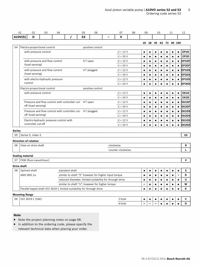
36 A10VO series 52 and 53 | Axial piston variable pumpDimensions size 45
Dimensions [in (mm)]
Dimensions size 45
DR – Hydraulic pressure controller, clockwise rotation, series 523)
(Ø10
1.6
)
4.00
03.
998
DIA
-0.0
540
(Ø10
1.6
)
4.00
03.
998
DIA
-0.0
540
2.06
(52
.4)
0.98
(Ø
25)
B
1.03(26.2)
8.31 (211)7.01 (178)
L
L1
3.90 (99)5.93 (150.5)
5.18
(13
1.5)
45°
6.77 (172)5.75 (146)
1.18 (30)0.25 (6.3)0.47 (12)0.37 (9.5)
1.41(35.7)
max. 8.68 (220.5)
1.50
(ø38
)
2.75
(69
.9)
S
0.56
(14
.3)
3.03
(77
)2.
70 (
68.5
)
BS Z
3.54 (90) 3.54 (90)
Y
max. 8.68 (220.5)
1.18(30)
7.44 (189)
L
L1
0.25 (6.3)
0.47 (12)3.90 (99)
0.37 (9.5)
1.50(38)
1.50(38)
BS
0.98
(ø2
5)2.
06(5
2.4)
30°
1.50
(ø3
8)
1.41(35.7)
1.03(26.2)
2.75
(69.
9)
30°
X3.1
(78)
1) Dimensions of working ports turned through 180° for counter-clockwise rotation2) Primary dimensions for pump apply to series 52 and 53
Ports see page 38
View Y1)
View X1)
Detail Z
▼ Port plate 61
▼ Port plate 62
Flange ISO 3019-1
Flange ISO 3019-1

RE-A 92703/12.2016, Bosch Rexroth AG
Axial piston variable pump | A10VO series 52 and 53 Dimensions size 45
37Dimensions [in (mm)]
▼ Splined shaft 1 in SAE J744 ▼ Splined shaft 1 in SAE J744
S ‒ 15T 16/32DP1) R ‒ 15T 16/32DP1)2)
1.81 (45.9)
0.63 (16)
0.20(5)
1.50 (38)
1.18 (30)
1/4-
20U
NC
-2B
3) 4
)
Usable shaft length
1/4-
20U
NC
-2B
3) 4
)
0.63 (16)
1.81 (45.9)
1.16(29.5)
0.20 (5)
▼ Splined shaft 7/8 in SAE J744 ▼ Splined shaft 7/8 in SAE J744
U ‒ 13T 16/32DP1) W ‒ 13T 16/32DP1)
1.61 (41)
0.63 (16)0.20 (5)
1.30 (33.1)
0.99(25.1)
1/4-
20U
NC
-2B
3) 4
)
Usable shaft length1/
4-20
UN
C-2
B3)
4) 0.63 (16)
1.61 (41)
0.98(25)
0.20 (5)
▼ Parallel keyed shaft (ISO 3019-1) ▼ Tapered with woodruff key (ISO 3019-1)
K ‒ 25-1 C
1.11
021.
1023
DIA
(28.
2
)
(ø25
.4
)
1.00
00.
998
1.81 (46)
0.63 (16)
1.50 (38.1)
0.2600.250 (6.35+0.25)
-0.0
3
0.98
(Ø25
)
-0.2
1/4-
20UN
C-2B
3) 4
)
0.20(5)
(3.2
)
-0.1
(6.35 )0.2500.251
0.25
00.
251
0.12
60.
130
+0.025
(6.3
5
)
+0.0
25A
B
2.43 (61.8)
0.16 (Ø4)1.18(30)
0.13 (3.2)
0.75 (19)125:1000
0.57 (14.4)
(Ø21
.774
)
0.85
750.
8570
DIA
+0.0
06-0
.006
5/8-
18UN
F-2A
3) 4
)
Key width

Bosch Rexroth AG, RE-A 92703/12.2016
38 A10VO series 52 and 53 | Axial piston variable pumpDimensions size 45
Dimensions [in (mm)]
1) Involute spline according to ANSI B92.1a, 30° pressure angle, flat root, side fit, tolerance class 5
2) Splines according to ANSI B92.1a, run out of spline is a deviation from standard.
3) Thread according to ASME B1.14) Observe the instructions in the operating instructions concerning
the maximum tightening torques.5) Momentary pressure spikes may occur depending on the application.
Keep this in mind when selecting measuring devices and fittings.
6) The spot face can be deeper than as specified in the standard.7) Depending on the installation position, L, L1 or L2 must be con-
nected (also see installation instructions starting on page 68).8) Only series 539) O = Must be connected (plugged when delivered)
X = Plugged (in normal operation)
Ports Standard Size4) pmax abs [psi (bar)]5) State9)
B Working port (Standard pressure series)Fastening thread
SAE J518ASME B1.1
1 in3/8-16UNC-2B; 0.71 (18) deep
4550 (315) O
S Suction port (standard pressure series)Fastening thread
SAE J518ASME B1.1
1 1/2 in1/2-13UNC-2B; 0.87 (22) deep
75 (5) O
L Drain port ISO 119266) 7/8-14UNF-2B; 0.51 (13) deep 30 (2) O7)
L1, L28) Drain port ISO 119266) 7/8-14UNF-2B; 0.51 (13) deep 30 (2) X7)
X Control pressure ISO 11926 7/16-20UNF-2A; 0.45 (11.5) deep 4550 (315) O

RE-A 92703/12.2016, Bosch Rexroth AG
Axial piston variable pump | A10VO series 52 and 53 Dimensions size 45
39Dimensions [in (mm)]
▼ DRG – Pressure controller, remote controlled, series 52 (53) ▼ EP.D. / EK.D. – Electro-proportional control, series 53
L
L1
5.93 (150.5)
5.18
(13
1.5)
max. 8.68 (220.5)2.68 (68)
X
S
4.53
(11
5)
4.57
(11
6)
1.38(35)
L
L1
L2
8.98 (228)5.75 (146) 2.68
(68)
XX
5.22
(13
2.5)
S
▼ DFR/DFR1/DRSC – Pressure and flow control, series 52 (53) ▼ EP.ED. / EK.ED. – Electro-proportional control, series 53
L
L1
5.93 (150.5)
5.18
(13
1.5)
max. 8.68 (220.5)2.68 (68)
X
S
4.53
(11
5)
1.42(36)
4.69
(11
9)
3.35 (85)
L
L1
L2
9.69 (246)
X
S
5.24
(13
3)
▼ LA.D. – Pressure, flow and power control, series 53 ▼ ED7. / ER7. – Electro-proportional Pressure control, series 52 (53)
4.58
(11
6.4)
2.68 (68)
L
L1
L2
9.25 (235)5.75 (146)
X
S
X
5.24
(13
3)
X
S
5.20
(13
2)1)
L
L1
9.84 (250)
LL
1) ER7.: 6.57 inch (167 mm) if using an intermediate plate pressure controller

Bosch Rexroth AG, RE-A 92703/12.2016
40 A10VO series 52 and 53 | Axial piston variable pumpDimensions size 60
Dimensions [in (mm)]
Dimensions size 60
DR – Hydraulic pressure controller, clockwise rotation, mounting flange C series 52
3.07
(78
)
1.69 (42.9)
S
L
7.93 (201.5)9.43 (239.5)
1.97
(Ø50
)
3.06
(77
.8)
B
2.06
(52
.4)
1.03(26.2)
0.98
(Ø
25)
0.25(6.3)
0.37(9.5)
45°
Z
X
Y
0.59(15)
X
4.61 (117)
5.75 (146)6.77 (172)
5.39
(13
7) L
L
L1
(78.5
)
1.57 (40)
2.83 (72) 2.83 (72)
0.56
(14
.3)
3.43
(87
)
BS
(Ø10
1.6
)
4.00
03.
998
DIN
-0.0
540
(Ø10
1.6
)
4.00
03.
998
DIN
-0.0
540
max. 8.68 (220.5)
1.30(33)
1.81 (46)2.
06(5
2.4)
0.98
(Ø
25)
1.97
(Ø
50)
3.06
(77
.8)
1.69 (42.9) 1.03 (26.2)
S B
0.37(9.5)
0.59 (15)
X
8.19 (208)
4.61 (117)
max. 8.68 (220.5)
1.57(40)
BS
1) Dimensions of working ports turned through 180° for counter-clockwise rotation
View Y1)
View X1)
Detail Z
▼ Port plate 61
▼ Port plate 62
Flange ISO 3019-1
Flange ISO 3019-1

RE-A 92703/12.2016, Bosch Rexroth AG
Axial piston variable pump | A10VO series 52 and 53 Dimensions size 60
41Dimensions [in (mm)]
Dimensions size 60
DR – Hydraulic pressure controller, clockwise rotation, mounting flange D series 52
max. 8.68 (220.5)
max. 8.68 (220.5)
2.83 (72) 2.83 (72)
3.07
(78
)
B
L
2.06
(52
.4)
1.03 (26.2)
0.98
(Ø
25)
0.50 (12.7)
Z
X
Y
4.51
(11
4.5)
5.83
(14
8)5.
41 (
137.
4)
3.43
(87
)
45°
5.75 (146)4.51 (114.5)
4.61 (117)1.57(40)
1.69(42.9)
S
7.93 (201.5)9.43 (239.5)
1.97
(Ø50
)3.
06 (
77.8
)
0.59 (15)
0.56(14.3)
BS
X
L
L
3.09 (
78.5)
L1
0.98
(Ø
25)
2.06
(52.
4)
8.19 (208)
1.30(33)
1.97
(Ø
50)
3.06
(77
.8)
1.67 (42.9) 1.03 (26.2)
S
B
1.81(46)
0.50(12.7)
0.24 (6)
(Ø12
7
)
5.00
004.
9975
DIA
-0
.063
0(Ø
127
)
5.00
004.
9975
DIA
-0
.063
0
4.61 (117)
1.57 (40)
X
0.59 (15)
1) Dimensions of working ports turned through 180° for counter-clockwise rotation
View Y1)
View X1)
Detail Z
▼ Port plate 61
▼ Port plate 62
Flange ISO 3019-1
Flange ISO 3019-1
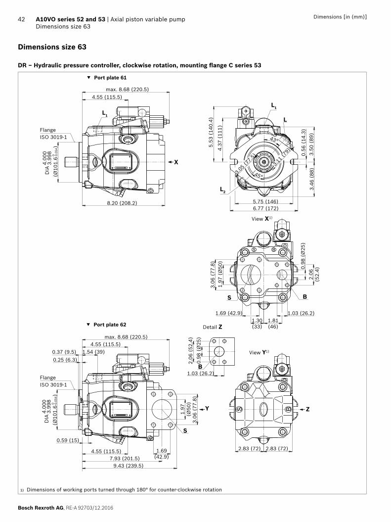
Bosch Rexroth AG, RE-A 92703/12.2016
42 A10VO series 52 and 53 | Axial piston variable pumpDimensions size 63
Dimensions [in (mm)]
Dimensions size 63
DR – Hydraulic pressure controller, clockwise rotation, mounting flange C series 53
2.83 (72) 2.83 (72)
ZY
X
max. 8.68 (220.5)
4.37
(11
1)
4.55 (115.5)
1.54 (39)
3.50
(89
)
5.75 (146)6.77 (172)
L1L1
L
L2
3.11 (
79)
43°
3.46
(88
)
45°3.0
5 (77
.5)
0.59 (15)
0.37 (9.5)0.25 (6.3)
BS
0.56
(14
.3)
5.53
(14
0.4)
9.43 (239.5)
S
1.69(42.9)
3.06
(77
.8)
1.97
(Ø50
)
7.93 (201.5)
4.55 (115.5)
B
2.06
(52
.4)
1.03 (26.2)
0.98
(Ø
25)
1.97
(Ø
50)
3.06
(77
.8)
1.69 (42.9) 1.03 (26.2)1.81(46)
1.30(33)
max. 8.68 (220.5)
BS
BS0.
98 (
Ø25
)2.
06(5
2.4)
8.20 (208.2)
4.55 (115.5)
(Ø10
1.6
)
4.00
03.
998
DIA
-0.0
540
(Ø10
1.6
)
4.00
03.
998
DIA
-0.0
540
1) Dimensions of working ports turned through 180° for counter-clockwise rotation
View Y1)
View X1)
Detail Z
▼ Port plate 61
▼ Port plate 62
Flange ISO 3019-1
Flange ISO 3019-1

RE-A 92703/12.2016, Bosch Rexroth AG
Axial piston variable pump | A10VO series 52 and 53 Dimensions size 63
43Dimensions [in (mm)]
Dimensions size 63
DR – Hydraulic pressure controller, clockwise rotation, mounting flange D series 53
9.43 (239.5)
S
1.69(42.9)
3.06
(77
.8)
1.97
(Ø50
)
7.93 (201.5)
B
2.06
(52
.4)
1.03(26.2)
2.83 (72)
5.75
(14
6)
max. 8.68 (220.5)
5.75 (146)
0.55 (
14)
4.51 (114.5)
4.51
(11
4.5)
ZY
X
4.55 (115.5)
3.50
(89
)
L1
L1
L
L2
3.11 (
79)
43°
5.91 (150)
3.46
(88
)
45°3.05 (
77.5)
BS
5.51
(14
0)4.
37 (
111)
45° 45°
X
4.55 (115.5)
8.19 (208)
max. 8.68 (220.5)
0.59 (15)
0.59 (15)
0.25 (6.3)1.54(39)
L1
(Ø12
7
)
5.00
004.
9975
DIA
-0.0
630
(Ø12
7
)
5.00
004.
9975
DIA
-0.0
630
0.50 (12.7)
0.25(6.3)
1.54 (39)0.50 (12.7)
X
4.55 (115.5)
0.98
(Ø
25)
2.06
(52
.4)
S B
1.81(46)
1.30(33)
1.97
(Ø
50)
3.06
(77
.8)
1.69(42.9) 1.03 (26.2)
2.83 (72)
0.98
(Ø
25)
1) Dimensions of working ports turned through 180° for counter-clockwise rotation
View Y1)
View X1)
Detail Z
▼ Port plate 61
▼ Port plate 62
Flange ISO 3019-1
Flange ISO 3019-1

Bosch Rexroth AG, RE-A 92703/12.2016
44 Dimensions [in (mm)]A10VO series 52 and 53 | Axial piston variable pumpDimensions size 63 (60)
▼ Splined shaft 1 1/4 in SAE J744 ▼ Splined shaft 1 1/4 in SAE J744
S ‒ 14T 12/24DP1) R ‒ 14T 12/24DP1)2)
2.18(55.4)
0.75 (19)
0.20 (5)
1.87 (47.5)
1.56(39.5)
5/16
-18U
NC
-2B
3) 4
)
Usable shaft length
5/16
-18U
NC
-2B
3) 4
) 0.75 (19)
2.18 (55.4)
1.50 (38)
0.20 (5)
▼ Splined shaft 1 in SAE J744 ▼ Splined shaft 1 in SAE J744
U ‒ 15T 16/32DP1) W ‒ 15T 16/32DP1)
1.81 (45.9)
0.63 (16)
0.20 (5)
1.50 (38)
0.98(25)
1/4-
20U
NC
-2B
3) 4
)
Usable shaft length1/
4-20
UN
C-2
B3)
4) 0.63 (16)
1.81 (45.9)
1.14 (29)
0.20 (5)
▼ Parallel keyed shaft (ISO 3019-1) ▼ Tapered with woodruff key (ISO 3019-1)
K ‒ 32-1 C
1.38
981.
3819
DIA
(35.
3
)
(ø31
.75
)
1.25
01.
249
2.18 (55.4)
0.75 (19)
1.87 (47.5)
0.32230.3125 (7.94+0.25)
-0.0
3
1.37
(Ø34
.91)
-0.2
1/4-
20UN
C-2B
3) 4
)
0.20(5)
(3.5
4
)-0
.1
(7.94 )0.31260.3136
0.13
550.
1394
+0.025
(7.9
4
)
0.31
260.
3136
+0.0
25A
B
2.61 (66.4)
0.16 (Ø4) 1.18(30)0.12 (3)
0.93 (23.6)
125:1000
0.56 (14.1)
(Ø31
.51
)
1.24
031.
2399
DIA
+0.0
06-0
.006
1-12
UNF-
2A3)
4)
Footnote see page 46
Key width

RE-A 92703/12.2016, Bosch Rexroth AG
45Dimensions [in (mm)] Axial piston variable pump | A10VO series 52 and 53 Dimensions size 63 (60)
1) Involute spline according to ANSI B92.1a, 30° pressure angle, flat root, side fit, tolerance class 5
2) Splines according to ANSI B92.1a, run out of spline is a deviation from standard.
3) Thread according to ASME B1.14) Observe the instructions in the operating instructions concerning
the maximum tightening torques.5) Momentary pressure spikes may occur depending on the application.
Keep this in mind when selecting measuring devices and fittings..
6) The spot face can be deeper than as specified in the standard.7) Depending on the installation position, L, L1 or L2 must be con-
nected (also see installation instructions starting on page 68).8) Only series 539) O = Must be connected (plugged when delivered)
X = Plugged (in normal operation)
Ports Standard Size4) pmax abs [psi (bar)]5) State9)
B Working port (Standard pressure series)Fastening thread
SAE J518ASME B1.1
1 in3/8-16UNC-2B; 0.71 (18) deep
4550 (315) O
S Suction port (standard pressure series)Fastening thread
SAE J518ASME B1.1
2 in1/2-13UNC-2B; 0.87 (22) deep
75 (5) O
L Drain port ISO 119266) 7/8-14UNF-2B; 0.51 (13) deep 30 (2) O7)
L1, L28) Drain port ISO 119266) 7/8-14UNF-2B; 0.51 (13) deep 30 (2) X7)
X Control pressure ISO 11926 7/16-20UNF-2A; 0.45 (11.5) deep 4550 (315) O

Bosch Rexroth AG, RE-A 92703/12.2016
46 Dimensions [in (mm)]A10VO series 52 and 53 | Axial piston variable pumpDimensions size 63 (60)
▼ DRG – Pressure controller, remote controlled, series 53 (52) ▼ EP.D. / EK.D. – Electro-proportional control, series 53
S
5.93 (150.5)
X
5.39
(13
7) LL1L1
4.76
(12
1)
2.56 (65)Xmax. 8.68 (220.5)
5.94 (151)9.49 (241)
4.92
(12
5)
L1
L
L2
X1.40
(35.6)
5.53
(14
0.4)
X
4.55 (115.5)2.55
(64.8)
4.88
(12
3.9)
S
▼ DFR/DFR1/DRSC – Pressure and flow control, series 53 (52) ▼ EP.ED. / EK.ED. – Electro-proportional control, series 53
S
5.93 (150.5)
X
5.39
(13
7) LL1L1
4.76
(12
1)
2.56 (65)Xmax. 8.68 (220.5)
9.86 (250.5)
4.92
(12
5)
L1
L
L2
1.42(36)
5.53
(14
0.4)
4.55 (115.5) 3.23 (82)
S
X
▼ LA.D. – Pressure, flow and power control, series 53 ▼ ED7. / ER7. – Electro-proportional Pressure control, series 53 (52)
L1
L
L2
5.51
(14
0)5.
04 (
128)
9.72 (247)2.56 (65)
S
X
4.88
(12
4)
X
5.91 (150) 9.88 (251)
5.39
(13
7)1)
SL
L1
L1
L
1) ER7.: 6.77 inch (172 mm) if using an intermediate plate pressure controller

RE-A 92703/12.2016, Bosch Rexroth AG
Axial piston variable pump | A10VO series 52 and 53 Dimensions size 72
47Dimensions [in (mm)]
Dimensions size 72
DR – Hydraulic pressure controller, clockwise rotation, mounting flange C series 53
2.83 (72) 2.83 (72)
ZY
X
max. 8.68 (220.5)
4.37
(11
1)
4.55 (115.5)
1.54 (39)
3.50
(89
)
5.75 (146)6.77 (172)
L1L1
L
L2
3.11 (
79)
43°
3.46
(88
)
45°3.0
5 (77
.5)
0.59 (15)
0.37 (9.5)0.25 (6.3)
BS
0.56
(14
.3)
5.53
(14
0.4)
9.43 (239.5)
S
1.69(42.9)
3.06
(77
.8)
1.97
(Ø50
)
7.93 (201.5)
4.55 (115.5)
B
2.06
(52
.4)
1.03 (26.2)
0.98
(Ø
25)
1.97
(Ø
50)
3.06
(77
.8)
1.69 (42.9) 1.03 (26.2)1.81(46)
1.30(33)
max. 8.68 (220.5)
BS
BS
0.98
(Ø
25)
2.06
(52.
4)
8.20 (208.2)
4.55 (115.5)
(Ø10
1.6
)
4.00
03.
998
DIA
-0.0
540
(Ø10
1.6
)
4.00
03.
998
DIA
-0.0
540
1) Dimensions of working ports turned through 180° for counter-clockwise rotation
View Y1)
View X1)
Detail Z
▼ Port plate 61
▼ Port plate 62
Flange ISO 3019-1
Flange ISO 3019-1

Bosch Rexroth AG, RE-A 92703/12.2016
48 A10VO series 52 and 53 | Axial piston variable pumpDimensions size 72
Dimensions [in (mm)]
Dimensions size 72
DR – Hydraulic pressure controller, clockwise rotation, mounting flange D series 53
9.43 (239.5)
S
1.69(42.9)
3.06
(77
.8)
1.97
(Ø50
)
7.93 (201.5)
B
2.06
(52
.4)
1.03(26.2)
2.83 (72)
5.75
(14
6)
max. 8.68 (220.5)
5.75 (146)
0.55 (
14)
4.51 (114.5)
4.51
(11
4.5)
ZY
X
4.55 (115.5)
3.50
(89
)
L1
L1
L
L2
3.11 (
79)
43°
5.91 (150)
3.46
(88
)
45°3.05 (
77.5)
BS
5.51
(14
0)4.
37 (
111)
45° 45°
X
4.55 (115.5)
8.19 (208)
max. 8.68 (220.5)
0.59 (15)
0.59 (15)
0.25 (6.3)1.54(39)
L1
(Ø12
7
)
5.00
004.
9975
DIA
-0.0
630
(Ø12
7
)
5.00
004.
9975
DIA
-0.0
630
0.50 (12.7)
0.25(6.3)
1.54 (39)0.50 (12.7)
X
4.55 (115.5)
0.98
(Ø
25)
2.06
(52
.4)
S B
1.81(46)
1.30(33)
1.97
(Ø
50)
3.06
(77
.8)
1.69(42.9) 1.03 (26.2)
2.83 (72)
0.98
(Ø
25)
1) Dimensions of working ports turned through 180° for counter-clockwise rotation
Ports see page 50
View Y1)
View X1)
Detail Z
▼ Port plate 61
▼ Port plate 62
Flange ISO 3019-1
Flange ISO 3019-1

RE-A 92703/12.2016, Bosch Rexroth AG
Axial piston variable pump | A10VO series 52 and 53 Dimensions size 72
49Dimensions [in (mm)]
▼ Splined shaft 1 1/4 in SAE J744 ▼ Splined shaft 1 1/4 in SAE J744
S ‒ 14T 12/24DP1) R ‒ 14T 12/24DP1)2)
2.18 (55.4)
0.75 (19)
0.20 (5)
1.87 (47.5)
1.56(39.5)
5/16
-18U
NC
-2B
3) 4
)
Usable shaft length
5/16
-18U
NC
-2B
3) 4
)
0.75 (19)
2.18 (55.4)
1.50(38)
0.20 (5)
▼ Splined shaft 1 in SAE J744 ▼ Splined shaft 1 in SAE J744
U ‒ 15T 16/32DP1) W ‒ 15T 16/32DP1)
1.81 (45.9)
0.63 (16)0.20 (5)
1.50 (38)
0.98(25)
1/4-
20U
NC
-2B
3) 4
)
Usable shaft length1/
4-20
UN
C-2
B3)
4) 0.63 (16)
1.81 (45.9)
1.14 (29)
0.20 (5)
▼ Parallel keyed shaft (ISO 3019-1)
K ‒ 32-1
1.38
981.
3819
DIA
(35.
3
)
(ø31
.75
)
1.25
01.
249
2.18 (55.4)
0.75 (19)
1.87 (47.5)
0.32230.3125 (7.94+0.25)
-0.0
3
1.37
(Ø34
.91)
-0.2
1/4-
20UN
C-2B
3) 4
)
0.20(5)
1) Involute spline according to ANSI B92.1a, 30° pressure angle, flat root, side fit, tolerance class 5
2) Splines according to ANSI B92.1a, run out of spline is a deviation from standard.
3) Thread according to ASME B1.14) Observe the instructions in the operating instructions concerning
the maximum tightening torques.
Key width

Bosch Rexroth AG, RE-A 92703/12.2016
50 A10VO series 52 and 53 | Axial piston variable pumpDimensions size 72
Dimensions [in (mm)]
Ports Standard Size1) pmax abs psi [bar]2) State6)
B Working port (Standard pressure series)Fastening thread
SAE J518ASME B1.1
1 in3/8-16UNC-2B; 0.71 (18) deep
4550 (315) O
S Suction port (standard pressure series)Fastening thread
SAE J518ASME B1.1
2 in1/2-13UNC-2B; 0.87 (22) deep
75 (5) O
L Drain port ISO 119263) 7/8-14UNF-2B; 0.51 (13) deep 30 (2) O4)
L1, L2 5) Drain port ISO 119263) 7/8-14UNF-2B; 0.51 (13) deep 30 (2) X4)
X Control pressure ISO 11926 7/16-20UNF-2A; 0.45 (11.5) deep 4550 (315) O
1) Observe the instructions in the operating instructions concerning the maximum tightening torques.
2) Momentary pressure spikes may occur depending on the application. Keep this in mind when selecting measuring devices and fittings.
3) The spot face can be deeper than as specified in the standard.
4) Depending on the installation position, L, L1 or L2 must be con-nected (also see installation instructions starting on page 68).
5) Only series 536) O = Must be connected (plugged when delivered)
X = Plugged (in normal operation)
RE-A 92703/12.2016, Bosch Rexroth AG
Axial piston variable pump | A10VO series 52 and 53 Dimensions size 72
51Dimensions [in (mm)]
▼ DRG – Pressure controller, remote controlled, series 53 ▼ EP.D. / EK.D. – Electro-proportional control, series 53
max. 8.68 (220.5)2.56 (65)
4.88
(12
4)5.
53 (
140.
5)
X
5.93 (150.5)
L
L2
X
S
5.94 (151)9.49 (241)
4.92
(12
5)
L1
L
L2
X1.40
(35.6)
5.53
(14
0.4)
X
4.55 (115.5)2.55
(64.8)
4.88
(12
3.9)
S
▼ DRF/DRS/DRSC – Pressure and flow control, series 53 ▼ EP.ED. / EK.ED. – Electro-proportional control, series 53
max. 8.68 (220.5)2.56 (65)
4.88
(12
4)5.
53 (
140.
5)
X
5.93 (150.5)
L
L2
X
S
9.86 (250.5)
4.92
(12
5)
L1
L
L2
1.42(36)
5.53
(14
0.4)
4.55 (115.5) 3.23 (82)
S
X
▼ LA.D. – Pressure, flow and power control, series 53 ▼ ED7. / ER7. – Electro-proportional Pressure control, series 53
L1
L
L2
5.51
(14
0)5.
04 (
128)
9.72 (247)2.56 (65)
S
X
4.88
(12
4)
X
5.91 (150) 9.86 (250.5)
5.53
(14
0.5)
1)X
L
L2S
1) ER7.: 6.91 inch (175.5 mm) if using an intermediate plate pressure controller

Bosch Rexroth AG, RE-A 92703/12.2016
52 A10VO series 52 and 53 | Axial piston variable pumpDimensions size 85
Dimensions [in (mm)]
Dimensions size 85
DR – Hydraulic pressure controller, clockwise rotation, mounting flange C series 52
3.74 (95) 3.35 (85)
S
L
2.00(50.8)9.27 (235.5)
10.91 (277)
Z
X
Y
max. 9.51 (241.5)5.12 (130)
BS
X
2.48
(Ø63
)3.
50 (
88.9
)
1.25(31.8)
2.63
(66
.7)
B1.26
(Ø
32)
S
B
(Ø12
7
)
5.00
004.
9975
DIA
-0.0
630
(Ø12
7
)
5.00
004.
9975
DIA
-0.0
630
2.63
(66.
7)
2.36
(Ø
60)
3.50
(88
.9) 1.
26 (
Ø32
)2.00
(50.8) 1.25 (31.8)1.97(50)
1.77(45)
6.14
(15
6)
max. 9.53 (242)5.12 (130)
X L
L1
9.65 (245)
0.50 (12.7)
0.79 (20)
1.57 (40)
0.50 (12.7)
0.79 (20)
1.57 (40)
7.13 (181)8.27 (210)
45°
3.74 (
95)
3.68
(93
.5)
3.42
(87
)0.
69 (
17.5
)
1) Dimensions of working ports turned through 180° for counter-clockwise rotation
Ports see page 55
View Y1)
View X1)
Detail Z
▼ Port plate 61
▼ Port plate 62
Flange ISO 3019-1
Flange ISO 3019-1

RE-A 92703/12.2016, Bosch Rexroth AG
Axial piston variable pump | A10VO series 52 and 53 Dimensions size 85
53Dimensions [in (mm)]
Dimensions size 85
DR – Hydraulic pressure controller, clockwise rotation, mounting flange D series 53
S3.74 (95) 3.35 (85)
2.63
(66
.7) 1.
26 (
Ø32
)
1.25(31.8)
B
9.25 (235)
2.48
(Ø63
)3.
50 (
88.9
)
10.91 (277)
2.00(50.8)
ZY
0.79 (20)
1.42 (36)
5.12 (130)
5.63 (143)
max. 9.90 (251.5)
0.50 (12.7)
1.42 (36)0.50 (12.7)
X
BS
9.65 (245)
45°
4.96
(12
6)
4.51
(11
4.5)
4.51 (114.5)5.75 (146)
0.56
(14.3
)
5.91
(15
0)
(Ø12
7
)
5.00
004.
9975
DIA
-0.0
630
(Ø12
7
)
5.00
004.
9975
DIA
-0.0
630
3.98
(10
1)4.
04 (
102.
5)
5.12 (130)
5.63 (143)
45°
3.74 (
95)
3.74 (
95)
0.16 (4)
0.16 (4)
L
L2
L1
X
max. 9.90 (251.5)
S B
2.63
(66.
7)
2.36
(Ø
60)
3.50
(88
.9) 1.
26 (
Ø32
)
2.00(50.8) 1.25 (31.8)
1.97(50)
1.77(45)
X
1) Dimensions of working ports turned through 180° for counter-clockwise rotation
Ports see page 55
View Y1)
View X1)
Detail Z
▼ Port plate 61
▼ Port plate 62
Flange ISO 3019-1
Flange ISO 3019-1

Bosch Rexroth AG, RE-A 92703/12.2016
54 A10VO series 52 and 53 | Axial piston variable pumpDimensions size 85
Dimensions [in (mm)]
▼ Splined shaft 1 1/2 in SAE J744 ▼ Splined shaft 1 1/2 in SAE J744
S ‒ 17T 12/24DP1) R ‒ 17T 12/24DP1)
2.44 (61.9)
1.10 (28)
0.20(5)
2.13 (54)
1.71(43.5)
7/16
-14U
NC
-2B
3) 4
)
7/16
-14U
NC
-2B
3) 4
) 1.10 (28)
2.44 (61.9)
1.65 (42)
0.20(5)
▼ Splined shaft 1 1/4 in SAE J744 ▼ Splined shaft 1 1/4 in SAE J744
U ‒ 14T 12/24DP1) W ‒ 14T 12/24DP1)
2.18 (55.4)
0.75 (19)0.20 (5)
1.87 (47.5)
1.38(35)
5/16
-18U
NC
-2B
3) 4
)
Usable shaft length
5/16
-18U
NC
-2B
3) 4
)
0.75 (19)
2.18 (55.4)
1.30 (33)
0.20 (5)
▼ Parallel keyed shaft (ISO 3019-1)
K ‒ 38-1
1.66
531.
6500
DIA
(42.
3
)
(ø38
.1
)
1.50
01.
499
2.44 (61.9)
1.10 (28)
2.10 (53.5)
0.37580.3748 (9.52+0.025)
-0.0
3
-0.4
7/16
-14U
NC-2
B 3) 4
)
0.20(5)
Key width
1) Involute spline according to ANSI B92.1a, 30° pressure angle, flat root, side fit, tolerance class 5
2) Splines according to ANSI B92.1a, run out of spline is a deviation from standard.
3) Thread according to ASME B1.14) Observe the instructions in the operating instructions concerning
the maximum tightening torques
Usable shaft length

RE-A 92703/12.2016, Bosch Rexroth AG
Axial piston variable pump | A10VO series 52 and 53 Dimensions size 85
55Dimensions [in (mm)]
Ports Standard Size4) pmax abs psi [bar]5) State8)
B Working port (Standard pressure series)Fastening thread
SAE J518ASME B1.1
1 1/4 in1/2-13UNC-2B; 0.75 (19) deep
4550 (315) O
S Suction port (standard pressure series)Fastening thread
SAE J518ASME B1.1
2 1/2 in1/2-13UNC-2B; 1.07 (27) deep
75 (5) O
L Drain port ISO 119266) 1 1/16-12UNF-2B; 0.59 (15) deep 30 (2) O7)
L1, L2 Drain port ISO 119266) 1 1/16-12UNF-2B; 0.59 (15) deep 30 (2) X7)
X Control pressure ISO 11926 7/16-20UNF-2A; 0.45 (11.5) deep 4550 (315) O
1) Observe the instructions in the operating instructions concerning the maximum tightening torques.
2) Momentary pressure spikes may occur depending on the application. Keep this in mind when selecting measuring devices and fittings.
3) The spot face can be deeper than as specified in the standard.
4) Depending on the installation position, L, L1 or L2 must be con-nected (also see installation instructions starting on page 68).
5) Only series 536) O = Must be connected (plugged when delivered)
X = Plugged (in normal operation)

Bosch Rexroth AG, RE-A 92703/12.2016
56 A10VO series 52 and 53 | Axial piston variable pumpDimensions size 85
Dimensions [in (mm)]
▼ DRG – Pressure controller, remote controlled, series 52 (53) ▼ EP.D. / EK.D. – Electro-proportional control, series 53
5.49
(139
.5)
X 2.91 (74)
6.14
(15
6) L
L1
S
max. 9.51 (241.5)6.75 (171.5)
X
1.42(36)X
5.59
(14
2)5.
91 (
150)
5.24
(13
3)
2.91(74)
7.15 (181.5)10.51 (267)
L
L2
L1X
S
▼ DRF/DRS/DRSC – Pressure and flow control, series 52 (53) ▼ EP.ED. / EK.ED. – Electro-prop. control, series 53
5.49
(139
.5)
X 2.91 (74)
6.14
(15
6) L
L1
S
max. 9.51 (241.5)6.75 (171.5)
X
S
5.24
(13
3)
2.91 (74)7.15 (181.5)11.06 (281)
X
5.91
(15
0) L
L2
L1
X
▼ LA.D. – Pressure, flow and power control, series 53 ▼ ED7. / ER7. – Electro-prop. Pressure control, series 52 (53)
X
S
5.71
(145
)5.
90 (
149.
9)
5.25
(13
3.4)
2.91 (74)7.15 (181.5)10.67 (271)
L
L2
L1X
0.76 (19.4)2.17 (55)
6.14
(15
6)1)
10.68 (271.4)
XL1
L
S
1) ER7.: 7.52 inch (191 mm) if using an intermediate plate pressure controller

RE-A 92703/12.2016, Bosch Rexroth AG
Axial piston variable pump | A10VO series 52 and 53 Dimensions size 100
57Dimensions [in (mm)]
Dimensions size 100
DR – Hydraulic pressure controller, clockwise rotation, mounting flange C series 53
S3.74 (95) 3.35 (85)
2.63
(66
.7) 1.
26 (
Ø32
)
1.25(31.8)
B
9.25 (235)
2.48
(Ø63
)3.
50 (
88.9
)
10.91 (277)
2.00(50.8)
0.79 (20)
1.42 (36)
5.12 (130)
5.63 (143)max. 9.90 (251.5)
0.50 (12.7)
1.42 (36)0.50 (12.7)
X
BS
9.65 (245)
(Ø12
7
)
5.00
004.
9975
DIA
-0.0
630
(Ø12
7
)
5.00
004.
9975
DIA
-0.0
630
5.12 (130)
5.63 (143)
X
max. 9.90 (251.5)
S B
2.62
(66.
7)
2.36
(Ø
60)
3.50
(88
.9) 1.
26(Ø
32)
2.00(50.8) 1.25
(31.8)1.97(50)
1.77(45)
0.16 (4)45°
5.91
(15
0)
3.98
(10
1)4.
03 (
102.
5)
7.13 (181)8.27 (210)
45°
3.74 (
95)
3.74 (
95)
0.16 (4)
0.69
(17
.5)
LL
L
L2
L1
L1
L1
X
Y Z
1) Dimensions of working ports turned through 180° for counter-clockwise rotation
View Y1)
View X1)
Detail Z
▼ Port plate 61
▼ Port plate 62
Flange ISO 3019-1
Flange ISO 3019-1

Bosch Rexroth AG, RE-A 92703/12.2016
58 A10VO series 52 and 53 | Axial piston variable pumpDimensions size 100
Dimensions [in (mm)]
Dimensions size 100
DR – Hydraulic pressure controller, clockwise rotation, mounting flange D series 53
S3.74 (95) 3.35 (85)
2.63
(66
.7) 1.
26(Ø
32)
1.25(31.8)
B
9.25 (235)
2.48
(Ø63
)
3.50
(88
.9)
10.91 (277)
2.00(50.8)
0.79 (20)
1.42 (36)
5.12 (130)
5.63 (143)
max. 9.90 (251.5)
0.50 (12.7)
1.42 (36)0.50 (12.7)
X
BS
9.65 (245)
0.16 (4)
45°
4.96
(12
6)
4.51
(11
4.5)
4.51 (114.5)5.75 (146)
0.56
(14.3
)
5.91
(15
0)
(Ø12
7
)
5.00
004.
9975
DIA
-0.0
630
(Ø12
7
)
5.00
004.
9975
DIA
-0.0
630
3.98
(10
1)4.
04 (
102.
5)
5.12 (130)
5.63 (143)
45°
3.74 (
95)
3.74 (
95)
0.16 (4)
L
L1
L
L1
L
L2
L1
X
max. 9.90 (251.5)
S B2.
62(6
6.7)
2.36
(Ø
60)
3.50
(88
.9) 1.
26 (
Ø32
)2.00
(50.8) 1.25(31.8)1.97
(50)1.77(45)
X
Y Z
1) Dimensions of working ports turned through 180° for counter-clockwise rotation
View Y1)
View X1)
Detail Z
▼ Port plate 61
▼ Port plate 62
Flange ISO 3019-1
Flange ISO 3019-1

RE-A 92703/12.2016, Bosch Rexroth AG
Axial piston variable pump | A10VO series 52 and 53 Dimensions size 100
59Dimensions [in (mm)]
▼ Splined shaft 1 1/2 in SAE J744 ▼ Splined shaft 1 1/4 in SAE J744
S ‒ 17T 12/24DP1) U ‒ 14T 12/24DP1)
2.44 (61.9)
1.10 (28)
0.20(5)
2.13 (54)
1.71(43.5)
7/16
-14U
NC
-2B
3) 4
)
2.18 (55.4)
0.75 (19)0.20 (5)
1.87 (47.5)
1.38(35)
5/16
-18U
NC
-2B
3) 4
)
▼ Splined shaft 1 1/4 in SAE J744 ▼ Parallel keyed shaft (ISO 3019-1)
W ‒ 14T 12/24DP1) K ‒ 38-1
Usable shaft length
5/16
-18U
NC
-2B
3) 4
)
0.75 (19)
2.18 (55.4)
1.30 (33)
0.20 (5)1.
6653
1.65
00
DIA
(42.
3
)
(ø38
.1
)
1.50
01.
499
2.44 (61.9)
1.10 (28)
2.10 (53.5)
0.37580.3748 (9.52+0.025)
-0.0
3
-0.4
7/16
-14U
NC-2
B 3) 4
)
0.20(5)
Ports Standard Size4) pmax abs [psi (bar)]5) Status9)
B Working port (high-pressure line)Fastening thread
SAE J518ASME B1.1
1 1/4 in1/2-13UNC-2B; 0.75 (19) deep
4550 (315) O
S Suction port (standard pressure series)Fastening thread
SAE J518ASME B1.1
2 1/2 in1/2-13UNC-2B; 1.07 (27) deep
75 (5) O
L Drain port ISO 119266) 1 1/16-12UNF-2B; 0.59 (15) deep 30 (2) O7)
L1, L28) Drain port ISO 119266) 1 1/16-12UNF-2B; 0.59 (15) deep 30 (2) X7)
X Control pressure ISO 11926 7/16-20UNF-2A; 0.45 (11.5) deep 4550 (315) O
Key width
1) Involute spline according to ANSI B92.1a, 30° pressure angle, flat root, side fit, tolerance class 5
2) Splines according to ANSI B92.1a, run out of spline is a deviation from standard.
3) Thread according to ASME B1.14) Observe the instructions in the operating instructions concerning
the maximum tightening torques.5) Momentary pressure spikes may occur depending on the application.
Keep this in mind when selecting measuring devices and fittings.
6) The spot face can be deeper than as specified in the standard.7) Depending on the installation position, L, L1 or L2 must be con-
nected (also see installation instructions starting on page 68).8) Only series 539) O = Must be connected (plugged when delivered)
X = Plugged (in normal operation)
Key width

Bosch Rexroth AG, RE-A 92703/12.2016
60 A10VO series 52 and 53 | Axial piston variable pumpDimensions size 100
Dimensions [in (mm)]
▼ DRG – Pressure controller, remote controlled, series 53 ▼ EP.D. / EK.D. – Electro-proportional control, series 53
S
5.24
(13
3)
2.91 (74)7.15 (181.5)max. 9.90 (251.5)
X
X
5.91
(15
0) L
L2
L1
1.42(36)X
5.59
(14
2)5.
91 (
150)
5.24
(13
3)
2.91(74)
7.15 (181.5)10.51 (267)
L
L2
L1X
S
▼ DRF/DRS/DRSC – Pressure and flow control, series 53 ▼ EP.ED. / EK.ED. – Electro-proportional control, series 53
S
5.24
(13
3)
2.91 (74)7.15 (181.5)max. 9.90 (251.5)
X
X
5.91
(15
0) L
L2
L1
S
5.24
(13
3)
2.91 (74)7.15 (181.5)11.06 (281)
X
5.91
(15
0) L
L2
L1
X
▼ LA.D. – Pressure, flow and power control, series 53 ▼ ED7. / ER7. – Electro-proportional Pressure control, series 53
X
S
5.71
(145
)5.
90 (
149.
9)
5.25
(13
3.4)
2.91 (74)7.15 (181.5)10.67 (271)
L
L2
L1X
S
10.71 (272)
X
6.14
(15
6)1)
L
L2
L1
1) ER7.: 7.52 inch (191 mm) if using an intermediate plate pres-sure controller

RE-A 92703/12.2016, Bosch Rexroth AG
Axial piston variable pump | A10VO series 52 and 53 Dimensions through drive
61Dimensions [in (mm)]
Dimensions through drive
Flange ISO 3019-1 (SAE) Hub for splined shaft1) Availability over sizes Code
Diameter Attachment2) Diameter 18 28 45 60/63 72 85 100
82-2 (A) , 5/8 in 9T 16/32DP ● ● ● ● ● ● ● K013/4 in 11T 16/32DP ● ● ● ● ● ● ● K52
● = Available ○ = On request
▼ 82-2
A4
A3
A2
0.39(10)
(ø82
.55
)
3.25
203.
2501
DIA
+0.0
50+0
.020A B
45°
4.19(106.5)
A1 (to mounting flange)
Omitted for size 18 and 28
Omitted for size 18 and 28
Section A-B
4.19(106.5)
A B
A4
45°
A3
0.39(10)A2
(ø82
.55
)
3.25
203.
2501
DIA
+0.0
50+0
.020
Omitted for size 18 and 28
Omitted for size 18 and 28
A1 (to mounting flange)
Section A-B
K01(SAE J744 16-4 (A))
NG A1 A2 A3 A43) K52(SAE J744 19-4 (A-B))
NG A1 A2 A3 A43)
18 7.17 (182)
0.37 (9.3)
1.70 (43.3)
M10; 0.57(14.5) deep
18 7.17 (182)
1.54 (39)
0.74 (18.8)
M10; 0.57(14.5) deep
28 8.03 (204)
0.39 (9.9)
1.85 (47)
M10; 0.63(16) deep
28 8.03 (204)
1.54 (39.3)
0.74 (18.8)
M10; 0.63(16) deep
45 9.02 (229)
0.42 (10.7)
2.09 (53)
M10; 0.63(16) deep
45 9.02 (229)
1.55 (39.4)
0.75 (18.9)
M10; 0.63(16) deep
60/63
10.04 (255)
0.37 (9.5)
2.32 (59)
M10; 0.63(16) deep
60/63
10.04 (255)
1.55 (39.4)
0.75 (18.9)
M10; 0.63(16) deep
72 10.04 (255)
0.37 (9.5)
2.32 (59)
M10; 0.63(16) deep
72 10.04 (255)
1.55 (39.4)
0.75 (18.9)
M10; 0.63(16) deep
85 11.89 (302)
0.53 (13.4)
2.68 (68)
M10; 0.79(20) deep
85 11.89 (302)
1.74 (44.1)
0.93 (23.6)
M10; 0.79(20) deep
100 11.89 (302)
0.53 (13.4)
2.68 (68)
M10; 0.79(20) deep
100 11.89 (302)
1.74 (44.1)
0.93 (23.6)
M10; 0.79(20) deep
1) According to ANSI B92.1a, 30° pressure angle, flat root, side fit, tolerance class 5
2) Mounting bores pattern viewed from through drive with control at top
3) Thread according to DIN 13, observe the instructions in the in-struction manual for the maximum tightening torques.

Bosch Rexroth AG, RE-A 92703/12.2016
62 A10VO series 52 and 53 | Axial piston variable pumpDimensions through drive
Dimensions [in (mm)]
1) According to ANSI B92.1a, 30° pressure angle, flat root, side fit, tolerance class 5
2) Mounting bores pattern viewed from through drive with control at top
3) Thread according to DIN 13, observe the instructions in the in-struction manual for the maximum tightening torques.
Flange ISO 3019-1 (SAE) Hub for splined shaft1) Availability over sizes Code
Diameter Attachment2) Diameter 18 28 45 60/63 72 85 100
101-2 (B) , 7/8 in 13T 16/32DP – ● ● ● ● ● ● K681 in 15T 16/32DP – – ● ● ● ● ● K04
● = Available ○ = On request
▼ 101-2
Omitted for sizes 28, 45
Omitted for sizes 28, 45
A1 (to mounting flange)
Section A-B
A4
45°
5.75(146)
A B
A3
0.39(10)A2
(ø10
1.6
)
4.00
204.
0008
DIA
+0.0
50+0
.020
Omitted for size 45
Omitted for size 45A1 (to mounting flange)
Section A-B
A4
45°
5.75(146)
A B
A3
A20.39(10)
(ø10
1.6
)
4.00
204.
0008
DIA
+0.0
50+0
.020
K68(SAE J744 22-4 (B))
NG A1 A2 A3 A43) K04(SAE J744 25-4 (B-B))
NG A1 A2 A3 A43)
28 8.03 (204)
1.66 (42.3)
0.70 (17.8)
M12; 0.71(18) deep
45 9.02(229)
1.88 (47.9)
0.74 (18.9)
M12; 0.71(18) deep
45 9.02 (229)
1.67 (42.4)
0.71 (17.9)
M12×1.75; 0.7118 deep
60/63
10.04 (255)
1.87 (47.4)
0.72 (18.4)
M12; 0.71(18) deep
60/63
10.04 (255)
1.67 (42.4)
0.71 (17.9)
M12; 0.71(18) deep
72 10.04 (255)
1.87 (47.4)
0.72 (18.4)
M12; 0.71(18) deep
72 10.04 (255)
1.67 (42.4)
0.71 (17.9)
M12; 0.71(18) deep
85 11.89 (302)
2.02 (51.2)
0.87 (22.2)
M12; 0.79(20) deep
85 11.89 (302)
1.83 (46.5)
0.87 (22)
M12; 0.79(20) deep
100 11.89 (302)
2.02 (51.2)
0.87 (22.2)
M12; 0.79(20) deep
100 11.89 (302)
1.83 (46.5)
0.87 (22)
M12; 0.79(20) deep

RE-A 92703/12.2016, Bosch Rexroth AG
Axial piston variable pump | A10VO series 52 and 53 Dimensions through drive
63Dimensions [in (mm)]
1) According to ANSI B92.1a, 30° pressure angle, flat root, side fit, tolerance class 5
2) Mounting bores pattern viewed from through drive with control at top
3) Thread according to DIN 13, observe the instructions in the in-struction manual for the maximum tightening torques.
Flange ISO 3019-1 (SAE) Hub for splined shaft1) Availability over sizes Code
Diameter Attachment2) Diameter 18 28 45 60/63 72 85 100
127-4 (C) 1 1/4 in 14T 12/24DP – – – ● ● ● ● K151 1/2 in 17T 12/24DP – – – – – ● ● K16
● = Available ○ = On request
▼ 127-4
Section A-B
A1 (to mounting flange)B
A
4.51
(11
4.5)
4.51 (114.5) A4 0.51(13)
A2A3
(ø12
7
)
5.00
205.
0008
DIA
+0.0
50+0
.020
A1 (to mounting flange)
Section A-B
(ø12
7
)
5.00
205.
0008
DIA
+0.0
50+0
.020
B
A
4.51
(11
4.5)
4.51 (114.5) A4 0.53(13.4)
A2A3
K15(SAE J744 32-4 (C))
NG A1 A2 A3 A43) K16(SAE J744 32-4 (C))
NG A1 A2 A3 A43)
60/63 10.04 (255)
0.31 (8)
2.32 (59)
M12; 0.63(16) deep
85 11.87(301.5)
0.51 (13)
2.67 (67.9)
M12;through
72 10.04 (255)
0.31 (8)
2.32 (59)
M12; 0.63(16) deep
100 11.87 (301.5)
0.51 (13)
2.67 (67.9)
M12;through
85 11.87 (301.5)
0.51 (13)
2.67 (67.9)
M12;through
100 11.87 (301.5)
0.51 (13)
2.67 (67.9)
M12;through
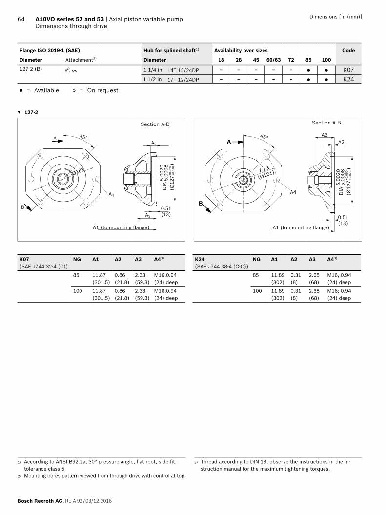
Bosch Rexroth AG, RE-A 92703/12.2016
64 A10VO series 52 and 53 | Axial piston variable pumpDimensions through drive
Dimensions [in (mm)]
1) According to ANSI B92.1a, 30° pressure angle, flat root, side fit, tolerance class 5
2) Mounting bores pattern viewed from through drive with control at top
3) Thread according to DIN 13, observe the instructions in the in-struction manual for the maximum tightening torques.
Flange ISO 3019-1 (SAE) Hub for splined shaft1) Availability over sizes Code
Diameter Attachment2) Diameter 18 28 45 60/63 72 85 100
127-2 (B) , 1 1/4 in 14T 12/24DP – – – – – ● ● K071 1/2 in 17T 12/24DP – – – – – ● ● K24
● = Available ○ = On request
▼ 127-2
A1 (to mounting flange)
Section A-B
0.51(13)
(Ø12
7
)
5.00
205.
0008
DIA
+0.0
50+0
.020
B
45°AA2
A3
A4
Ø181
A1 (to mounting flange)
Section A-B
A4
A
B
45°
7.13
(Ø181)
A3A2
0.51(13)
(Ø12
7
)
5.00
205.
0008
DIA
+0.0
50+0
.020
K07(SAE J744 32-4 (C))
NG A1 A2 A3 A43) K24(SAE J744 38-4 (C-C))
NG A1 A2 A3 A43)
85 11.87 (301.5)
0.86 (21.8)
2.33 (59.3)
M16;0.94(24) deep
85 11.89 (302)
0.31 (8)
2.68 (68)
M16; 0.94(24) deep
100 11.87 (301.5)
0.86 (21.8)
2.33 (59.3)
M16;0.94(24) deep
100 11.89 (302)
0.31 (8)
2.68 (68)
M16; 0.94(24) deep

RE-A 92703/12.2016, Bosch Rexroth AG
Axial piston variable pump | A10VO series 52 and 53 Overview of attachment options
65Dimensions [in (mm)]
Overview of attachment options
Through drive Attachment options – 2nd pump
Flange ISO 3019-1
Hub for splined shaft
Code A10V(S)O/5x NG (shaft) A10VO/31 NG (shaft) A1VO/10 NG (shaft) External gear
82-2 (A) 5/8 in K01 10 (U), 18 (U) 18 (U) 18 (S2) AZPF3/4 in K52 10 (S), 18 (S, R) 18 (S, R) 18 (S3)
101-2 (B) 7/8 in K68 28 (S, R)45 (U, W)1)
28 (S, R)45 (U,W)
35 (S4) AZPN/AZPG
1 in K04 45 (S, R)60, 63 (U, W)2)
72 (U, W)2)
45 (S, R) 35 (S5) –
127-4 (C) 1 1/4 in K15 60, 63 (S, R)72 (S, R)
– – –
1 1/2 in K16 85 (S)100 (S)
– – –
127-2 (C) 1 1/4 in K07 85 (U,W)100 (U,W)
71 (S, R) – PGH5
1 1/2 in K24 85 (S)100 (S)
– – –
1) Not for NG28 with K682) Not for NG45 with K04

Bosch Rexroth AG, RE-A 92703/12.2016
66 A10VO series 52 and 53 | Axial piston variable pumpCombination pumps A10VO + A10VO
Dimensions [in (mm)]
Combination pumps A10VO + A10VO
By using combination pumps, it is possible to have inde-pendent circuits without the need for splitter gearboxes. When ordering combination pumps, the type designations of the 1st and 2nd pump must be linked by a "+".Order example: A10VO85DRS/53R-VSC62K04+ A10VO45DRF/53R-VSC61N00It is permissible to use a combination of two single pumps of the same nominal size (tandem pump) considering a dynamic mass acceleration of maximum 10 g (= 98.1 m/s2) without additional support brackets. For combination pumps consisting of more than two pumps, the mounting flange must be rated for the permis-sible mass torque (please consult us).
Permissible mass moment of inertia
NG 10 18 28 45 60/63 72 85 100
static Tm lb-ft(Nm)
– 369(500)
656(890)
664(900)
1010(1370)
1010(1370)
2270(3080)
2270(3080)
dynamic at 10 g (98.1 m/s2) Tm lb-ft(Nm)
– 37(50)
65(89)
66(90)
101(137)
101(137)
227(308)
227(308)
Weight with through-drive plateWeight without through-drive plate (e.g. 2nd pump)
m lbs (kg) – (–)8 (18)
29 (13)25 (11.5)
40 (18)33 (15)
53 (24)40 (18)
62 (28)49 (22)
62 (28)49 (22)
99 (45)79 (36)
99 (45)79 (36)
Distance, center of gravitywithout through drive
l1 in(mm)
– 3.07(78)
3.35(85)
3.78(96)
4.13(105)
4.13(105)
4,80(122)
4.80 (122)
Distance, center of gravitywith through drive
l1 in(mm)
– 3.43(87)
3.90(99)
4.53(115)
5.00(127)
5.00(127)
5.90(150)
5.90 (150)
l1l2
m2m1
m1, m2, m3 Weight of pump [lbs (kg)]
l1, l2, l3 Distance, center of gravity [in (mm)]
Tm = (m1 × l1 + m2 × l2 + m3 × l3) ×1
[lb-ft (Nm)]12 (102)

RE-A 92703/12.2016, Bosch Rexroth AG
Axial piston variable pump | A10VO series 52 and 53 Connector for solenoids
67Dimensions [in (mm)]
Connector for solenoids
DEUTSCH DT04-2PMolded connector, 2-pin, without bidirectional suppressor diode The following type of protection ensues with a mounted mating connector:
▶ IP67 (DIN/EN 60529) and ▶ IP69K (DIN 40050-9)
▼ Circuit diagram symbol
▼ Mating connector DEUTSCH DT06-2S-EP04
Consisting of DT designation
1 housing DT06-2S-EP04
1 wedge W2S
2 sockets 0462-201-16141
The mating connector is not included in the scope of delivery. This can be supplied by Bosch Rexroth on request (material number R902601804).
Electronic controls
Control Electronics function Electronics Data sheet
Electric pressure control Controlled power outlet RA analog 95230
RC4-5/30 digital 95205
1.44
(36
.7) (2)
(1)
1.44 (36.7)
2.70 (68.5)
DIA
1.4
6(ø
37)
1.97 (50)
Changing plug positionIf necessary, you can change the position of the connector by turning the solenoid.To do this, proceed as follows:
▶ Loosen the mounting nut (1) of the solenoid. To do this, turn the mounting nut (1) one revolution counter-clockwise.
▶ Turn the solenoid body (2) to the desired orientation. ▶ Re-tighten the mounting nut.
Tightening torque: 3.7+0.75 lb-ft (5+1 Nm). (WAF 26, 12-sided DIN 3124)
On delivery, the position of the connector may differ from that shown in the brochure or drawing.

Bosch Rexroth AG, RE-A 92703/12.2016
68 A10VO series 52 and 53 | Axial piston variable pumpInstallation instructions
Dimensions [in (mm)]
1) Because complete air bleeding and filling are not possible in this position, the pump should be air bled and filled in a horizontal po-sition before installation.
2) For NG10 and NG28 series 52, L1 is opposite, L must then be con-nected if necessary.
3) Only series 53
Installation instructions
GeneralThe axial piston unit must be filled with hydraulic fluid and air bled during commissioning and operation. This must also be observed following a longer standstill as the axial piston unit may empty via the hydraulic lines.Particularly with the "drive shaft up/down" installation position, filling and air bleeding must be carried out com-pletely as there is, for example, a danger of dry running.The case drain fluid in the pump housing must be directed to the reservoir via the highest available drain port (L, L1
2), L2
3)).For combinations of multiple units, the case drain fluid must be drained off at each pump. If a shared reservoir line is used for several units, make sure that the case pressure in each pump is not exceeded. The shared drain line must be dimensioned to ensure that the maximum permissible case pressure of all connected units is not exceeded in any operational circumstances, particularly at cold start. If this is not possible, separate drain lines must be laid if neces-sary.To achieve favorable noise values, decouple all connecting lines using elastic elements and avoid above-reservoir installation. In all operating conditions, the suction line and drain line must flow into the reservoir below the minimum fluid level. The permissible suction height hS results from the overall loss of pressure. However, it must not be higher than hS max = 31.5 in (800 mm). The minimum suction pressure at port S must also not fall below 12 psi (0.8 bar) absolute during operation and during cold start.When designing the reservoir, ensure adequate distance between the suction line and the case drain line. This prevents the heated, return flow from being drawn directly back into the suction line.NoteIn certain installation positions, an influence on the con-trol characteristic can be expected. Gravity, dead weight and case pressure can cause minor shifts in control char-acteristic curves and changes in response time.
For key, see page 70.
Installation position See the following examples 1 to 12. Additional installation positions are possible upon request.Recommended installation position: 1 and 3
Below-reservoir installation (standard)Below-reservoir installation is when the axial piston unit is installed outside of the reservoir and below the minimum fluid level.
Installation position Air bleeding Filling
1 2)
LL1
S
X
ht min SB
F
h min
F S + L or L1
2 1)
X
SB
F
L
L1
S
ht min
h min
F S + L1
3 3)
L
L2
L1
S
SB
Fht min
h min
F S + L or L1
4
SB
F
LL1
S
ht min
h min
F S + L or L1

RE-A 92703/12.2016, Bosch Rexroth AG
Axial piston variable pump | A10VO series 52 and 53 Installation instructions
69Dimensions [in (mm)]
1) Because complete air bleeding and filling are not possible in this position, the pump should be air bled and filled in a horizontal po-sition before installation.
2) For NG10 and NG28 series 52, L1 is opposite, L must then be con-nected if necessary.
3) Only series 53
Above-reservoir installationAbove-reservoir installation means that the axial piston unit is installed above the minimum fluid level of the reservoir. To prevent the axial piston unit from draining, a height difference hES min of at least 1 in (25 mm) is required in position 6Observe the maximum permissible suction height hS max = 31.5 in (800 mm).
Installation position Air bleeding Filling
5 2)
X
LL1
S
F
SB
hs max
ht minh min
F L1 or L
61)2)
SB
S
F
LL1
hs max
ht minh min
hES min
X
F L1
7 3)
L
L2
SL1
F
SB
hs max
ht minh min
F L2
8 1)
SB
SF
LL1
hs max
ht minh min
F S or L
A check valve in the case drain line is only permissible in individual cases. Consult us for approval.
For key, see page 70.

Bosch Rexroth AG, RE-A 92703/12.2016
70 A10VO series 52 and 53 | Axial piston variable pumpInstallation instructions
Dimensions [in (mm)]
1) Because complete air bleeding and filling are not possible in this position, the pump should be air bled and filled in a horizontal po-sition before installation.
2) For NG10 and NG28 series 52, L1 is opposite, L must then be con-nected if necessary.
3) Only series 53
Reservoir installationInside-reservoir installation is when the axial piston unit is installed in the reservoir below the minimum fluid level. The axial piston unit is completely below the hydraulic fluid.If the minimum fluid level is equal to or below the upper edge of the pump, see chapter "Above-reservoir installation".Axial piston units with electric components (e.g. electric controls, sensors) must not be installed in a reservoir below the fluid level.
Installation position Air bleeding Filling
9 2)
LL1
S
h min
SB h t min
X
Via the high-est available port L
Automatically via the open port L or L1
due to the position un-der the hy-draulic fluid level
10
L
L1
S
SB
h min
h t min
X
Via the high-est available port L1
Automatically via the open port L, L1 or S
due to the position un-der the hy-draulic fluid level
11 3)
L
L2
SSB
h min
h t min
12
LL1
S SB
h min
h t min
Via the high-est available port L
Automatically via the open port L, L1 or S
due to the position un-der the hy-draulic fluid level
Key and assembly note
Key
F Filling / air bleeding
S Suction port
L; L1 Drain port
SB Baffle (baffle plate)
ht min Minimum required immersion depth (7.87 in (200 mm)
hmin Minimum required distance to reservoir bottom 3.94 in (100 mm)
hES min Minimum necessary height required to protect the axial piston unit from draining (1 in (25 mm)
hS max Maximum permissible suction height 21.50 in (800 mm)
NotePort F is part of the external piping and must be provided on the customer side to make filling and air bleeding easier.

RE-A 92703/12.2016, Bosch Rexroth AG
Axial piston variable pump | A10VO series 52 and 53 Installation instructions
71Dimensions [in (mm)]

72
Bosch Rexroth AG, RE-A 92703/12.2016
A10VO series 52 and 53 | Axial piston variable pumpProject planning notes
Bosch Rexroth CorporationMobile Applications8 Southchase CourtFountain Inn, SC 29644-9018USATelephone (864) 967-2777Facsimile (864) 967-8900www.boschrexroth-us.com
© Bosch Rexroth CorporationAll rights reserved. Neither this document, nor any part of it, may be repro-duced, duplicated, circulated or disseminated, whether by copy, electronic format or any other means, without the prior consent and authorization of Bosch Rexroth Corp.The data and illustrations in this brochure/data sheet are intended only to describe or depict the products. No representation or warranty, either express or implied, relating to merchantability or fitness for intended use, is given or intended by virtue of the information contained in this brochure/data sheet. The information contained in this brochure/data sheet in no way relieves the user of its obligation to insure the proper use of the products for a specific use or application. All products contained in this brochure/data sheet are subject to normal wear and tear from usage.Subject to change.
Bosch Rexroth Corporation2315 City Line RoadBethlehem, PA 18017-2131, USATelephone (610) 694-8300Facsimile (610) 694-8467www.boschrexroth-us.com
A10VO series 52 and 53 | Axial piston variable pumpProject planning notes and Safety instructions
Project planning notes
▶ The A10VO axial piston variable pump is designed to be used in open circuit.
▶ The project planning, installation and commissioning of the axial piston unit requires the involvement of quali-fied personnel.
▶ Before using the axial piston unit, please read the corre-sponding instruction manual completely and thoroughly. If necessary, request it from Bosch Rexroth.
▶ Before finalizing your design, please request a binding installation drawing.
▶ The specified data and notes must be observed. ▶ Depending on the operating conditions of the axial
piston unit (operating pressure, fluid temperature), the characteristic may shift.
▶ Preservation: Our axial piston units are supplied as stan-dard with protection to preserve for a maximum of 12 months. If longer preservative protection is required (maximum 24 months), please specify this in plain text when placing your order. The preservation periods apply under optimal storage conditions, details of which can be found in the data sheet 90312 or the instruction manual.
▶ Not all variants of the product are approved for use in safety functions according to ISO 13849. Please consult the responsible contact person at Bosch Rexroth if you require reliability parameters (e.g. MTTFd) for functional safety.
▶ Depending on the type of control used, electromagnetic effects can be produced when using solenoids. When a direct current is applied, solenoids do not cause electro-magnetic interference nor is their operation impaired by electromagnetic interference. Other behavior can result when a modulated direct current (e.g. PWM signal) is applied. Potential electro-magnetic interference for persons (e.g. persons with a pacemaker) and other components must be tested by the machine manufacturer.
▶ Pressure controllers are not safeguards against pressure overload. Be sure to add a pressure relief valve to the hydraulic system.
▶ Working ports: – The ports and fastening threads are designed for the
specified maximum pressure. The machine or system manufacturer must ensure that the connecting ele-ments and lines correspond to the intended operating conditions (pressure, flow, hydraulic fluid, tempera-ture) with allowance for the necessary safety margins.
– The working ports and function ports can only be used to accommodate hydraulic lines.
Safety instructions
▶ During and shortly after operation, there is a risk of burns on the axial piston unit and especially on the solenoids. Take appropriate safety measures (e.g. by wearing protective clothing).
▶ Moving parts in control equipment (e.g. valve spools) can, under certain circumstances, get blocked in posi-tion as a result of contamination (e.g. impure hydraulic fluid, abrasion, or residual dirt from components). As a result, the flow of hydraulic fluid and the build-up of torque in the axial piston unit can no longer respond correctly to the operator’s specifications. Even the use of various filter elements (external or internal flow filter) will not rule out a fault but merely reduce the risk. The machine/system manufacturer must test whether reme-dial measures are needed on the machine for the appli-cation concerned in order to set the consumer being driven to a safe position (e.g. safe stop) and if necessary to ensure it is properly implemented.