Axial Piston Variable Displacement Pump A11VO 92 500_66938414-4EB… · RE 92 500/06.04 | A11VO...
60
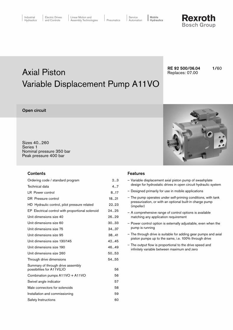
Industrial Hydraulics Electric Drives and Controls Linear Motion and Assembly Technologies Pneumatics Service Automation Mobile Hydraulics Features – Variable displacement axial piston pump of swashplate design for hydrostatic drives in open circuit hydraulic system – Designed primarily for use in mobile applications – The pump operates under self-priming conditions, with tank pressurization, or with an optional built-in charge pump (impeller) – A comprehensive range of control options is available matching any application requirement – Power control option is externally adjustable, even when the pump is running – The through drive is suitable for adding gear pumps and axial piston pumps up to the same, i.e. 100% through drive – The output flow is proportional to the drive speed and infinitely variable between maximum and zero Contents Ordering code / standard program 2...3 Technical data 4...7 LR Power control 8...17 DR Pressure control 18...21 HD Hydraulic control, pilot pressure related 22..23 EP Electrical control with proportional solenoid 24...25 Unit dimensions size 40 26...29 Unit dimensions size 60 30...33 Unit dimensions size 75 34...37 Unit dimensions size 95 38...41 Unit dimensions size 130/145 42...45 Unit dimensions size 190 46...49 Unit dimensions size 260 50...53 Through drive dimensions 54...55 Summary of through drive assembly possibilites for A11V(L)O 56 Combination pumps A11VO + A11VO 56 Swivel angle indicator 57 Male connectors for solenoids 58 Installation and commissioning 59 Safety Instructions 60 Axial Piston Variable Displacement Pump A11VO Open circuit Sizes 40...260 Series 1 Nominal pressure 350 bar Peak pressure 400 bar RE 92 500/06.04 1/60 Replaces: 07.00
Transcript of Axial Piston Variable Displacement Pump A11VO 92 500_66938414-4EB… · RE 92 500/06.04 | A11VO...
IndustrialHydraulics
Electric Drivesand Controls
Linear Motion andAssembly Technologies Pneumatics
ServiceAutomation
MobileHydraulics
Features– Variable displacement axial piston pump of swashplate
design for hydrostatic drives in open circuit hydraulic system
– Designed primarily for use in mobile applications
– The pump operates under self-priming conditions, with tankpressurization, or with an optional built-in charge pump(impeller)
– A comprehensive range of control options is availablematching any application requirement
– Power control option is externally adjustable, even when thepump is running
– The through drive is suitable for adding gear pumps and axialpiston pumps up to the same, i.e. 100% through drive
– The output flow is proportional to the drive speed andinfinitely variable between maximum and zero
ContentsOrdering code / standard program 2...3
Technical data 4...7
LR Power control 8...17
DR Pressure control 18...21
HD Hydraulic control, pilot pressure related 22..23
EP Electrical control with proportional solenoid 24...25
Unit dimensions size 40 26...29
Unit dimensions size 60 30...33
Unit dimensions size 75 34...37
Unit dimensions size 95 38...41
Unit dimensions size 130/145 42...45
Unit dimensions size 190 46...49
Unit dimensions size 260 50...53
Through drive dimensions 54...55
Summary of through drive assemblypossibilites for A11V(L)O 56
Combination pumps A11VO + A11VO 56
Swivel angle indicator 57
Male connectors for solenoids 58
Installation and commissioning 59
Safety Instructions 60
Axial PistonVariable Displacement Pump A11VO
Open circuit
Sizes 40...260Series 1Nominal pressure 350 barPeak pressure 400 bar
RE 92 500/06.04 1/60Replaces: 07.00

2/60 Bosch Rexroth AG | Mobile Hydraulics A11VO | RE 92 500/06.04
Ordering Code / Standard Program
Axial piston unitSwashplate design, variable displacement A11V
Charge pump (impeller) 40 60 75 95 130 145 190 260without charge pump (no code) with charge pump – – – – L
OperationPump, open circuit O
Size Displacement Vg max (cm3) 40 60 75 95 130 145 190 260
Control device 40 60 75 95 130 145 190 260Power control LR LR
with override cross-sensing negative LR C LR . Chigh pressure related negative LR3 LR3pilot pressure related negative LG1 LG1
positive LG2 LG2electrical 12V negative LE1 LE1
24V negative LE2 LE2with pressure cut-off D L . D. .
hydraulic 2-stage E L . E . .hydraulic remote controlled G L . . G .
with load sensing S L . . . Selectr. prop. override, 24V S2 L . . . S2hydr. prop. override S5 L . . . S5
with stroke limiter negative characteristic ∆p = 25 bar H1 L . . . H1∆p = 10 bar H5 L . . . H5
positive characteristic ∆p = 25 bar H2 L . . . H2∆p = 10 bar H6 L . . . H6U = 12 V U1 L . . . U1U = 24 V U2 L . . . U2
Pressure control DR DRwith load sensing DRS DRSremote controlled DRG DRGfor parallel operation DRL DRL
Hydraulic control ∆p = 10 bar HD1 HD1pilot pressure related (pos. characteristic) ∆p = 25 bar HD2 HD2
with pressure cut-off D HD. Dwith pressure cut-off, remote controlled G HD. G
Electrical control U = 12 V EP1 EP1with proportional solenoid (pos. characteristic)U = 24 V EP2 EP2
with pressure cut-off D EP. Dwith pressure cut-off, remote controlled G EP. G
Series1
IndexSize 40...130 0Size 145...260 1
Direction of rotationviewed on shaft end clockwise R
anti-clockwise L
In case of controls with several additional functions, observe the order of the columns, only one option per column is possible(e.g. LRDCH2).
The following combinations are not available for the power control:
LRDS2, LRDS5, L...GS, L...GS2, L...GS5, L...EC and the combination L...DG in connection with the stroke limiters H1, H2, H5, H6,U1 and U2.
= available
= available on request
– = not available
= preferred program

RE 92 500/06.04 | A11VO Mobile Hydraulics | Bosch Rexroth AG 3/60
Axial piston unit
Charge pump
Operation
Size
Control device
Series
Index
Direction of rotation
SealsNBR (nitrile-caoutchouc), shaft seal in FKM (fluor-caoutchouc) N
Shaft end (perm. input torques see page 7) 40 60 75 95 130 145 190 260Splined shaft DIN 5480 for single and combi pump ZCylindrical shaft with key DIN 6885 PSplined shaft ANSI B92.1a–1976 for single pump S
for combination pump –1) –1) –1) T
Mounting flange 40 60 75 95 130 145 190 260SAE J744 – 2-hole – – – – – – CSAE J744 – 4-hole – – DSAE J617 2) (SAE 3) – – – – G
Service line ports 40 60 75 95 130 145 190 260SAE pressure and suction port on (opposite) sides,
12with metric fastening threads
Through drive (see page 56 for attachments)Flange SAE J744 3) Splined shaft coupler 40 60 75 95 130 145 190 260– – N0082-2 (A) 5/8in 9T 16/32DP (A) K01
3/4in 11T 16/32DP (A-B) K52101-2 (B) 7/8in 13T 16/32DP (B) K02
1in 15T 16/32DP (B-B) K04W35 2x30x16x9g K79
127-2 (C) 4) 1 1/4in 14T 12/24DP (C) – K071 1/2in 17T 12/24DP (C-C) – – – K24W30 2x30x14x9g – K80W35 2x30x16x9g – K61
152-4 (D) 1 1/4in 14T 12/24DP (C) – – K861 3/4in 13T 8/16DP (D) – – – – K17W40 2x30x18x9g – – K81W45 2x30x21x9g – – – K82W50 2x30x24x9g – – – – K83
165-4 (E) 1 3/4in 13T 8/16DP (D) – – – – – – K72W50 2x30x24x9g – – – – – – K84W60 2x30x28x9g – – – – – – – K67
Swivel angle indicator (page 57) 40 60 75 95 130 145 190 260without (no code) with optical swivel angle indicator – Vwith electrical swivel angle sensor – R
Male connectors for solenoids 5) (page 58) 40 60 75 95 130 145 190 260DEUTSCH DT04-2P-EP04 (2-pole), moulded on the solenoid coil PHirschmann according to DIN EN 175 301-803-A H(not for new projects)
1) S-shaft suitable for combination pump!2) To fit the flywheel housing of the combustion engine3) 2 2-hole; 4 4-hole4) Size 190 and 260 with 2 + 4-hole flange5) Male connector without bidirectional surpressor diode6) no code = standard version, S = special version, K = combination with mounting part or mounting pump
A11V O / 1 – N 12 – 6)
4/60 Bosch Rexroth AG | Mobile Hydraulics A11VO | RE 92 500/06.04
5
10
40
60
20
100
200
400600
100016002500 0° 20° 40° 60° 80° 100°-40° -20°
16
36
5
1600
-40° -25° -10° 10° 30° 50° 90° 115°70°0°
VG
22
VG
32
VG
46
VG
68
VG
100
Hydraulic fluidFor detailed information on the choice of hydraulic fluidsand application conditions, please see our catalog pagesRE 90220 (mineral oil), RE 90221 (environmentally acceptablehydraulic fluids) and RE 90223 (HF-hydraulic fluids) prior toconfiguration.
The variable displacement pump A11VO is unsuitable foroperation with HFA, HFB and HFC. When using HF- orenvironmentally acceptable (Eco-evaluated) hydraulic fluidspossible restrictions in the technical data may have to be takenin consideration. If required please consult with our technicalsupport department. The hydraulic fluide type used should bestated on the order.
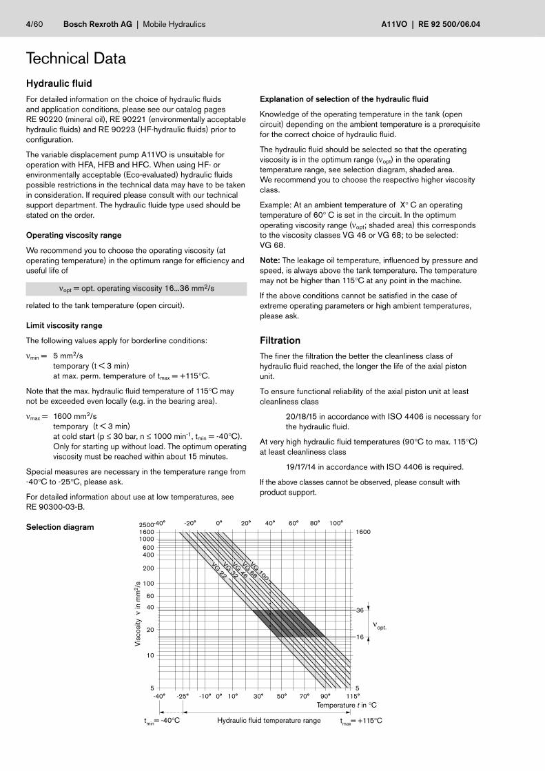
Operating viscosity range
We recommend you to choose the operating viscosity (atoperating temperature) in the optimum range for efficiency anduseful life of
νopt = opt. operating viscosity 16...36 mm2/s
related to the tank temperature (open circuit).
Limit viscosity range
The following values apply for borderline conditions:
νmin = 5 mm2/stemporary (t < 3 min)at max. perm. temperature of tmax = +115°C.
Note that the max. hydraulic fluid temperature of 115°C maynot be exceeded even locally (e.g. in the bearing area).
νmax = 1600 mm2/stemporary (t < 3 min)at cold start (p ≤ 30 bar, n ≤ 1000 min-1, tmin = -40°C).Only for starting up without load. The optimum operatingviscosity must be reached within about 15 minutes.
Special measures are necessary in the temperature range from-40°C to -25°C, please ask.
For detailed information about use at low temperatures, seeRE 90300-03-B.
Selection diagram
Explanation of selection of the hydraulic fluid
Knowledge of the operating temperature in the tank (opencircuit) depending on the ambient temperature is a prerequisitefor the correct choice of hydraulic fluid.
The hydraulic fluid should be selected so that the operatingviscosity is in the optimum range (νopt) in the operatingtemperature range, see selection diagram, shaded area.We recommend you to choose the respective higher viscosityclass.
Example: At an ambient temperature of X° C an operatingtemperature of 60° C is set in the circuit. In the optimumoperating viscosity range (νopt; shaded area) this correspondsto the viscosity classes VG 46 or VG 68; to be selected:VG 68.
Note: The leakage oil temperature, influenced by pressure andspeed, is always above the tank temperature. The temperaturemay not be higher than 115°C at any point in the machine.
If the above conditions cannot be satisfied in the case ofextreme operating parameters or high ambient temperatures,please ask.
FiltrationThe finer the filtration the better the cleanliness class ofhydraulic fluid reached, the longer the life of the axial pistonunit.
To ensure functional reliability of the axial piston unit at leastcleanliness class
20/18/15 in accordance with ISO 4406 is necessary forthe hydraulic fluid.
At very high hydraulic fluid temperatures (90°C to max. 115°C)at least cleanliness class
19/17/14 in accordance with ISO 4406 is required.
If the above classes cannot be observed, please consult withproduct support.
Technical Data
Temperature t in °C
Visc
osity
ν in
mm
2 /s
Hydraulic fluid temperature range tmax= +115°Ctmin= -40°C
νopt.

RE 92 500/06.04 | A11VO Mobile Hydraulics | Bosch Rexroth AG 5/60
1,2
0,8 0,9 1,00,9
1,0
1,1
T1
T2R
Vg minVg max
M1 S
AMG
0,5 0,6 0,7 0,8 0,9 1,0
15
10
5
Technical DataOperating pressure range
Inlet
Absolute pressure at port S (suction port)
Version without charge pump
pabs min __________________________________________________________ 0.8 bar
pabs max __________________________________________________________ 30 bar
If the pressure is > 5 bar, please ask.
Version with charge pump
pabs min __________________________________________________________ 0.6 bar
pabs max ____________________________________________________________ 2 bar
Maximum permissible speed (speed limit)
Permissible speed by increasing the inlet pressure pabs at thesuction port S or at Vg ≤ Vg max
Case drain pressureThe case drain pressure at the ports T1 and T2 maybe a maximum 1.2 bar higher than the inlet pressure at the portS but not higher than
pL abs. max ____________________________________________________________ 2 bar.
An unrestricted, full size case drain line directly to tank isrequired.
Temperature range of the shaft sealThe FKM shaft seal ring is permissible for housingtemperatures of -25°C to +115°C.
Note:For applications below -25°C, an NBR shaft seal is necessaryas a special version (permissible temperature range: -40°C to+90°C).State NBR shaft seal in clear text in the order.
Flushing the housingIf a variable displacement pump with control device EP, HD,DR or stroke limiter (H., U.) is operated over a long period(t > 10 min) with flow zero or operating pressure < 15 bar,flushing of the housing via ports "T1", "T2" or "R" is necessary.
size 40 60 75 95 130 145 190 260
qV flush (L/min) 2 3 3 4 4 4 5 6
The housing flushing is unnecessary in versions with chargepump (A11VLO), since a part of the charge flow is directed tothe housing. Higher case drain flow beyond volumetric rotarygroup losses and control flow may be noticed.
Charge pump (impeller)The charge pump is a circulating pump with which the A11VLO(size 130...260) is filled and therefore can be operated athigher speeds. This also simplifies cold starting at lowtemperatures and high viscosity of the hydraulic fluid. Tankcharging is therefore unnecessary in most cases. A tankpressurization of a max. 2 bar is permissible with charge pump.
Outlet
Pressure at port A or B
Nominal pressure pN __________________________________________ 350 bar
Peak pressure pmax ____________________________________________ 400 bar
Minimum operating pressure
A minimum operating pressure pB min is required in the pumpservice line depending on the speed, the swivel angle and thedisplacement (see diagram).
pabs = 1 bar
pabs = 1.5 bar
Spe
ed n
max
/nm
ax1
Displacement Vg / Vg max
V g /2
– V
g m
ax
Min
imum
ope
ratin
g pr
essu
re p
B m
in in
bar
n/nmax, perm.
V g <
Vg
/2

6/60 Bosch Rexroth AG | Mobile Hydraulics A11VO | RE 92 500/06.04
Technical DataValue table(theoretical values, without efficiencies and tolerances; values rounded)
Size A11VO 40 60 75 95 130 145 190 260
A11VLO (with charge pump) 130 145 190 260
Displacement Vg max cm3 42 58.5 74 93.5 130 145 193 260 130 145 193 260
Vg min cm3 0 0 0 0 0 0 0 0 0 0 0 0
Speedmaximum at Vg max
1) nmax min–1 3000 2700 2550 2350 2100 2200 2100 1800 2500 2) 2500 2) 2500 2) 23002)
maximum at Vg ≤ Vg max 3) nmax1 min–1 3500 3250 3000 2780 2500 2500 2500 2300 2500 2500 2500 2300
Flow 4)
at nmax and Vg maxqV max L/min 126 158 189 220 273 319 405 468 325 363 483 598
Power at qV max
and ∆p = 350 barPmax kW 74 92 110 128 159 186 236 273 190 211 281 349
Torque at Vg max
and ∆p = 350 barTmax Nm 234 326 412 521 724 808 1075 1448 724 808 1075 1448
Mass moment of inertia
around drive axisJ kgm2 0.0048 0.0082 0.0115 0.0173 0.0318 0.0341 0.055 0.0878 0.0337 0.036 0.0577 0.0895
Rotational vibration 4)
Angular acceleration, max. α rad/s2 22000 17500 15000 13000 10500 9000 6800 4800 10500 9000 6800 4800
Speed variation, max. ∆n min-1 85 73 68 63 57 49 37 28 57 49 37 28
Frequency limit flimit Hz 788 731 675 626 563 563 563 518 563 563 563 518
Rotary stiffness Shaft end Z Nm/rad 88894 102440 145836 199601 302495 302495 346190 686465 302495 302495 346190 686465
Shaft end P Nm/rad 87467 107888 143104 196435 312403 312403 383292 653835 312403 312403 383292 653835
Shaft end S Nm/rad 58347 86308 101921 173704 236861 236861 259773 352009 236861 236861 259773 352009
Shaft end T Nm/rad 74476 102440 125603 – – – 301928 567115 – – 301928 567115
Filling volume L 1.1 1.35 1.85 2.1 2.9 2.9 3.8 4.6 2.9 2.9 3.8 4.6
Weight (approx.) m kg 32 40 45 53 66 76 95 125 72 73 104 138
1) The values apply at absolute pressure (pabs) 1 bar at the suction port S and mineral hydraulic fluid.2) The values apply at absolute pressure (pabs) of at least 0.8 bar at the suction port S and mineral hydraulic fluid.3) The values apply at Vg ≤ Vg max or in case of an increase in the inlet pressure pabs at the suction port S (see diagram page 5)4) The permissible angular acceleration or speed variation only applies for single pumps, not for combi pumps.
The load on connection parts (e.g. through drive) must be taken into account additionally.At f < flimit the ∆n specified in the table is permissible.At f > flimit the permissible angular acceleration α specified in the table limits the value of the speed variation:∆nperm = 3.04 • α/f.
Determining the nominal value
Vg • n • ηv
Flow qv = L/min1000
Vg • ∆pTorque T = Nm
20 • π • ηmh
2 π • T • n qv • ∆pPower P = = kW
60 000 600 • ηt
Vg = Displacement per revolution cm3
∆p = Differential pressure bar
n = Speed rpm
ηv = volumetric efficiency
ηmh = mechanical-hydraulic efficiency
ηt = overall efficiency (ηt = ηv • ηmh)
asdasd
RE 92 500/06.04 | A11VO Mobile Hydraulics | Bosch Rexroth AG 7/60
2. Pumpe1. Pumpe
TE
TD
T1 T2
a,b,c
Fq
-
+Fax
1.Pump 2nd pump
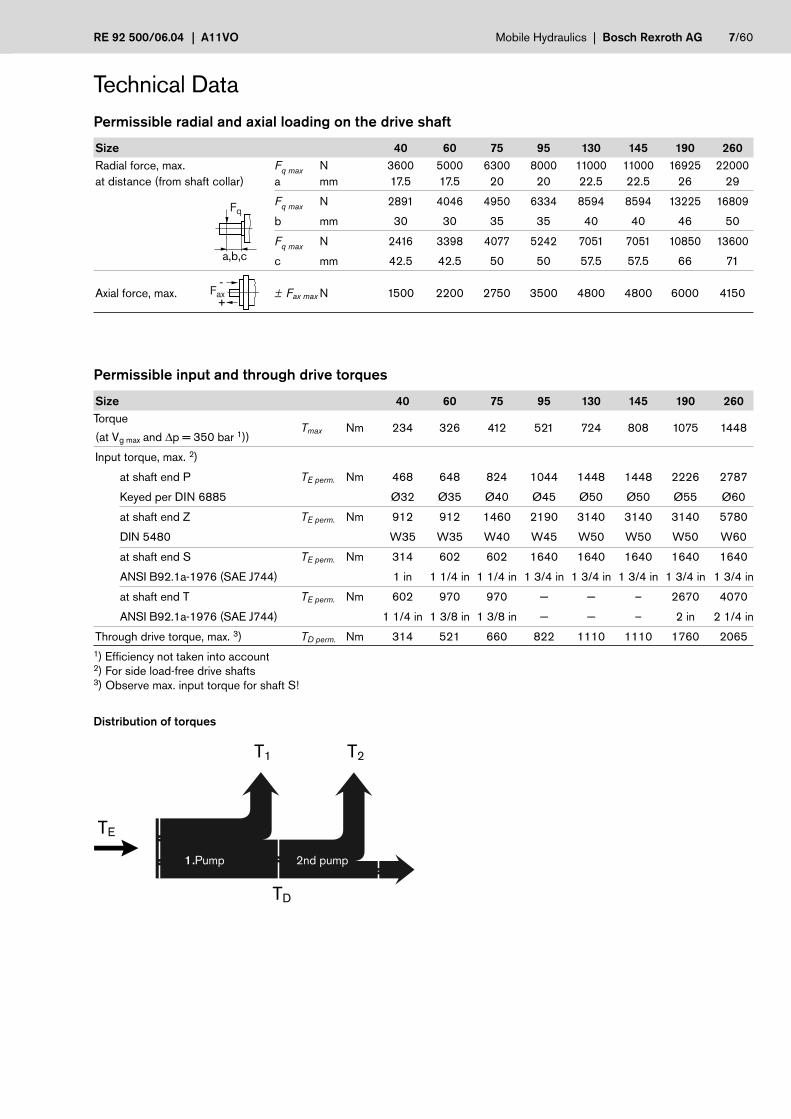
Technical DataPermissible radial and axial loading on the drive shaft
Size 40 60 75 95 130 145 190 260Radial force, max. Fq max N 3600 5000 6300 8000 11000 11000 16925 22000at distance (from shaft collar) a mm 17.5 17.5 20 20 22.5 22.5 26 29
Fq max N 2891 4046 4950 6334 8594 8594 13225 16809
b mm 30 30 35 35 40 40 46 50
Fq max N 2416 3398 4077 5242 7051 7051 10850 13600
c mm 42.5 42.5 50 50 57.5 57.5 66 71
Axial force, max. ± Fax max N 1500 2200 2750 3500 4800 4800 6000 4150
Permissible input and through drive torques
Size 40 60 75 95 130 145 190 260Torque
Tmax Nm 234 326 412 521 724 808 1075 1448(at Vg max and ∆p = 350 bar 1))
Input torque, max. 2)
at shaft end P TE perm. Nm 468 648 824 1044 1448 1448 2226 2787
Keyed per DIN 6885 Ø32 Ø35 Ø40 Ø45 Ø50 Ø50 Ø55 Ø60
at shaft end Z TE perm. Nm 912 912 1460 2190 3140 3140 3140 5780
DIN 5480 W35 W35 W40 W45 W50 W50 W50 W60
at shaft end S TE perm. Nm 314 602 602 1640 1640 1640 1640 1640
ANSI B92.1a-1976 (SAE J744) 1 in 1 1/4 in 1 1/4 in 1 3/4 in 1 3/4 in 1 3/4 in 1 3/4 in 1 3/4 in
at shaft end T TE perm. Nm 602 970 970 — — – 2670 4070
ANSI B92.1a-1976 (SAE J744) 1 1/4 in 1 3/8 in 1 3/8 in — — – 2 in 2 1/4 in
Through drive torque, max. 3) TD perm. Nm 314 521 660 822 1110 1110 1760 20651) Efficiency not taken into account2) For side load-free drive shafts3) Observe max. input torque for shaft S!
Distribution of torques
8/60 Bosch Rexroth AG | Mobile Hydraulics A11VO | RE 92 500/06.04
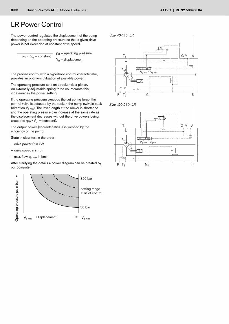
320 bar
50 bar
Vg max Vg min
M1 S
AMGT1
T2R
T1
T2R
Vg minVg max
M1 S
AMG
LR Power ControlThe power control regulates the displacement of the pumpdepending on the operating pressure so that a given drivepower is not exceeded at constant drive speed.
pB • Vg = constantpB = operating pressure
Vg = displacement
The precise control with a hyperbolic control characteristic,provides an optimum utilization of available power.
The operating pressure acts on a rocker via a piston.An externally adjustable spring force counteracts this,it determines the power setting.
If the operating pressure exceeds the set spring force, thecontrol valve is actuated by the rocker, the pump swivels back(direction Vg min). The lever length at the rocker is shortenedand the operating pressure can increase at the same rate asthe displacement decreases without the drive powers beingexceeded (pB • Vg = constant).
The output power (characteristic) is influenced by theefficiency of the pump.
State in clear text in the order:
– drive power P in kW
– drive speed n in rpm
– max. flow qV max in l/min
After clarifying the details a power diagram can be created byour computer.
Size 40-145: LR
Size 190-260: LR
Ope
ratin
g pr
essu
re p
B in
bar
DisplacementVg min Vg max
setting rangestart of control
RE 92 500/06.04 | A11VO Mobile Hydraulics | Bosch Rexroth AG 9/60
Vg max Vg min
M1 S
AMGT1
T2R
pHDZ
pHD
LRVg max Vg min
M1 S
AMGT1
T2R
Z
Z
T1
T2R
Vg minVg max
M1 S
AMG
Z
T1
T2R
Vg minVg max
M1
AMG
S
pHD
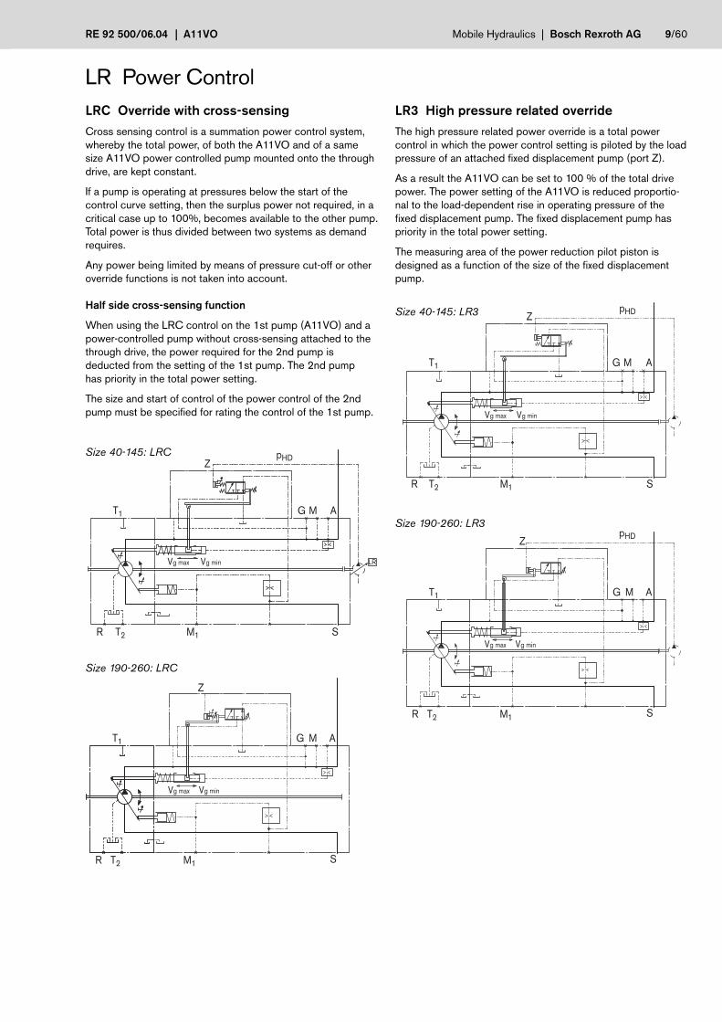
LR Power ControlLRC Override with cross-sensingCross sensing control is a summation power control system,whereby the total power, of both the A11VO and of a samesize A11VO power controlled pump mounted onto the throughdrive, are kept constant.
If a pump is operating at pressures below the start of thecontrol curve setting, then the surplus power not required, in acritical case up to 100%, becomes available to the other pump.Total power is thus divided between two systems as demandrequires.
Any power being limited by means of pressure cut-off or otheroverride functions is not taken into account.
Half side cross-sensing function
When using the LRC control on the 1st pump (A11VO) and apower-controlled pump without cross-sensing attached to thethrough drive, the power required for the 2nd pump isdeducted from the setting of the 1st pump. The 2nd pumphas priority in the total power setting.
The size and start of control of the power control of the 2ndpump must be specified for rating the control of the 1st pump.
Size 40-145: LRC
LR3 High pressure related overrideThe high pressure related power override is a total powercontrol in which the power control setting is piloted by the loadpressure of an attached fixed displacement pump (port Z).
As a result the A11VO can be set to 100 % of the total drivepower. The power setting of the A11VO is reduced proportio-nal to the load-dependent rise in operating pressure of thefixed displacement pump. The fixed displacement pump haspriority in the total power setting.
The measuring area of the power reduction pilot piston isdesigned as a function of the size of the fixed displacementpump.
Size 40-145: LR3
Size 190-260: LRC
Size 190-260: LR3

10/60 Bosch Rexroth AG | Mobile Hydraulics A11VO | RE 92 500/06.04
Z
Vg max Vg min
M1 S
AMGT1
T2R
Vg max Vg min
M1 S
AMGT1
T2R
Z
Z
T1
T2R
Vg minVg max
M1 S
AMG
Z
T1
T2R
Vg minVg max
M1 S
AMG
LR Power ControlLG1/2 Pilot pressure related overrideThis power control works by overriding the control setting withan external pilot pressure signal. This pilot pressure acts on theadjustment spring of the power regulator via port Z.
The mechanically adjusted basic setting can be hydraulicallyadjusted by means of different pilot pressure settings, enablingdifferent power mode settings.
If the pilot pressure signal is then adjusted by means of aexternal power limiting control, the total hydraulic powerconsumption of all users can be adapted to the available drivepower from the engine.
The pilot pressure used for power control is generated by anexternal control element that is not a component part of theA11VO (e.g. see also data sheet RE 95310, Electronic LoadLimiting Control, LLC).
LG1 Negative power override
Power control with negative override, LG1: the force resultingfrom the pilot pressure is acting against the mechanicaladjustment spring of the power control.
Increasing the pilot pressure reduces the power setting.
Size 40-145: LG1
Size 190-260: LG1
LG2 Positive power override
Power control with positive override, LG2: the force resultingfrom the pilot pressure is additive the mechanical adjustmentspring of the power control.
An increase in pilot pressure increases the power output.
Size 40-145: LG2
Size 190-260: LG2

RE 92 500/06.04 | A11VO Mobile Hydraulics | Bosch Rexroth AG 11/60
Vg max Vg min
M1 S
AMGT1
T2R
T1
T2R
Vg minVg max
M1 S
AMG
LR3LRC
LG2
LG1LE1/2
pHD I pSt
50
LE1/2 Electrical override (negative)Contrary to hydraulic power control override, the basic powersetting is reduced by an electrical pilot current applied to aproportional solenoid. The resulting force is acting against themechanical power control adjustment spring.
Increase in current = decrease in power
If the pilot current signal is adjusted by a load limiting control(e.g. LLC control RE 95310) the power consumption of allmechanical and hydraulic actuators is decreasing the A11VOpower setting to match the remaining available power from theengine.
A 12V (LE1) or 24V (LE2) supply is required for the control ofthe proportion solenoid.
Technical data of solenoids
LE1 LE2
Voltage 12 V DC (±20 %) 24 V DC (±20 %)
Control current
Start of control 400 mA 200 mA
End of control 1200 mA 600 mA
Limiting current 1.54 A 0.77 A
Nominal resistance (at 20°C) 5.5 Ω 22.7 Ω
Dither frequency 100 Hz 100 Hz
Duty cycle 100 % 100%
Type of protection dependent on connector version, see page 58
LR Power ControlSize 40-145: LE1/2
Size 190-260: LE1/2
Overview of power overrides
Effect of power overrides at rising pressure or current
Ope
ratin
g pr
essu
re p
B in
bar
Vg min Vg maxDisplacement
min

12/60 Bosch Rexroth AG | Mobile Hydraulics A11VO | RE 92 500/06.04
350
50
350
370
390
320
Y
T1
T2R
Vg minVg max
M1 S
AMG
Vg max Vg min
M1 S
AMGT1
T2R
LRE Power control with pressure cut-off,2-stage
By connecting an external pilot pressure to port Y, the basicvalue of the pressure cut-off can be increased by 50 +20 barand a 2nd pressure setting implemented.
This value is usually above the primary pressure relief valvesetting and therefore disables the pressure cut-off function.
The pressure signal at port Y must be between 20 and 50 bar.
Characteristic: LRE
LRD Power control with pressure cut-offPressure cut-of is a pressure control that adjusts the pumpdisplacement back towards Vg min when a preset pressurevalue is reached.
This function overrides the power control, i.e. below the presetpressure value, the power function is effective.
The pressure cut-off function is integrated into the pumpcontrol module and is preset to a specified value at the factory.
Setting range from 50 to 350 bar
Characteristic: LRD
LR Power ControlSize 40-145: LRD
Size 190-260: LRE
LRG Power control with pressure cut-off,hydraulically remote controlled
See page 20 for description and characteristic (pressurecontrol remote controlled, DRG)
max
min
Ope
ratin
g pr
essu
re p
B in
bar
setti
ng ra
nge
DisplacementVg min Vg max
increased pressure cut-off with tolerance range disable pressure cut-off
primary pressure relief valve
basic value pressure cut-off
Ope
ratin
g pr
essu
re p
B in
bar
DisplacementVg min Vg max
RE 92 500/06.04 | A11VO Mobile Hydraulics | Bosch Rexroth AG 13/60
350
50
Vg max Vg min
M1 S
AMGT1
T2R
X
X
T1
T2R
Vg minVg max
M1 S
AMG
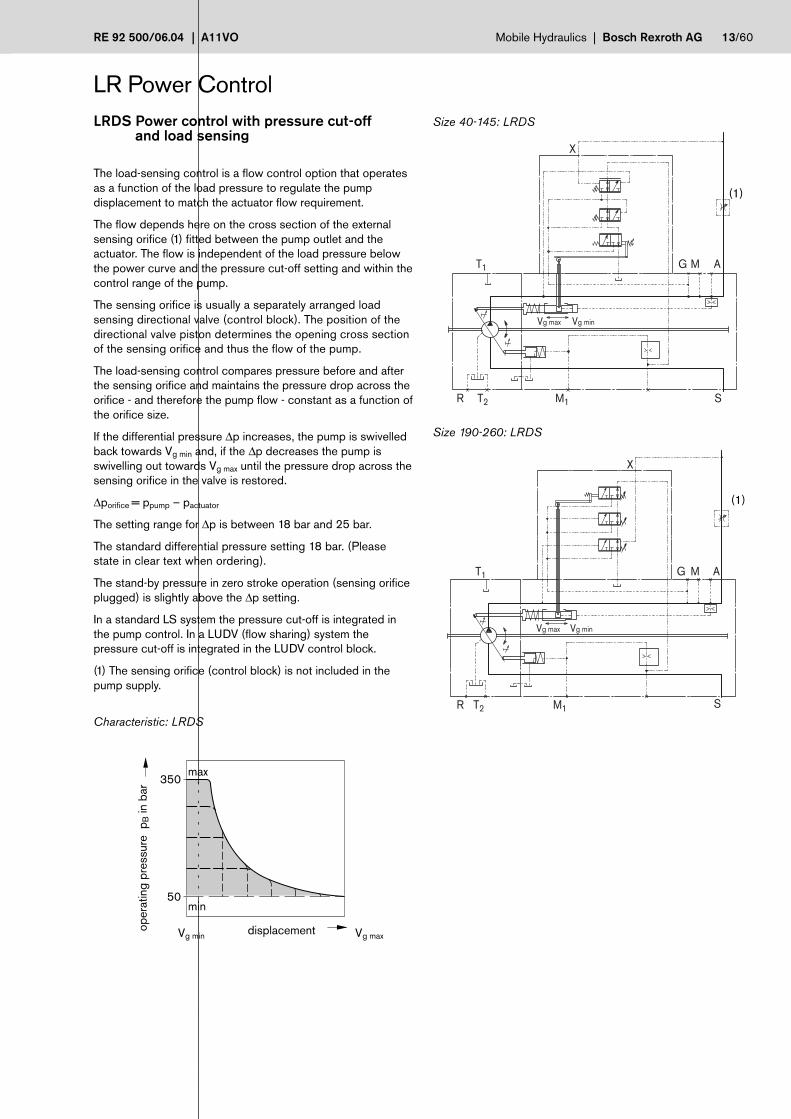
LRDS Power control with pressure cut-off and load sensing
The load-sensing control is a flow control option that operatesas a function of the load pressure to regulate the pumpdisplacement to match the actuator flow requirement.
The flow depends here on the cross section of the externalsensing orifice (1) fitted between the pump outlet and theactuator. The flow is independent of the load pressure belowthe power curve and the pressure cut-off setting and within thecontrol range of the pump.
The sensing orifice is usually a separately arranged loadsensing directional valve (control block). The position of thedirectional valve piston determines the opening cross sectionof the sensing orifice and thus the flow of the pump.
The load-sensing control compares pressure before and afterthe sensing orifice and maintains the pressure drop across theorifice - and therefore the pump flow - constant as a function ofthe orifice size.
If the differential pressure ∆p increases, the pump is swivelledback towards Vg min and, if the ∆p decreases the pump isswivelling out towards Vg max until the pressure drop across thesensing orifice in the valve is restored.
∆porifice = ppump – pactuator
The setting range for ∆p is between 18 bar and 25 bar.
The standard differential pressure setting 18 bar. (Pleasestate in clear text when ordering).
The stand-by pressure in zero stroke operation (sensing orificeplugged) is slightly above the ∆p setting.
In a standard LS system the pressure cut-off is integrated inthe pump control. In a LUDV (flow sharing) system thepressure cut-off is integrated in the LUDV control block.
(1) The sensing orifice (control block) is not included in thepump supply.
Characteristic: LRDS
LR Power Control
(1)
(1)
oper
atin
g pr
essu
re p
B in
bar
displacementVg min Vg max
min
max
Size 40-145: LRDS
Size 190-260: LRDS

14/60 Bosch Rexroth AG | Mobile Hydraulics A11VO | RE 92 500/06.04
25
181410
5
0 5 10 15 20 25 30
25
181410
5
200 300 400 500 600
M1 S
AMGT1
T2R
X
Vg max Vg min Vg max Vg min
M1 S
AMGT1
T2R
XZ
X
T1
T2R
Vg minVg max
M1 S
AMG
XZ
T1
T2R
Vg minVg max
M1 S
AMG
LRS2 Power control with load sensing,electrically override
This control option adds a proportional solenoid to override tothe mechanically set load-sensing pressure. The pressuredifferential change is proportional to the solenoid current.
Increasing current = smaller ∆p-setting
See following characteristic for details (example).
This permits a change in flow with the same sensing orificesize, to improve control resolution of the control block.Please consult us when applying.
For solenoid specification, see page 11 (LE2)
Characteristic: LRS2
LR Power ControlLRS5 Power control with load sensing,
hydraulically overrideThis control option adds an external proportional pilot pressuresignal (to port Z) to override the mechanically set load-sensingpressure.
Increasing pilot pressure = smaller ∆p-setting
See following characteristic for details (example).
This permits a change in flow with the same sensing orificesize, to improve control resolution of the control block.Please consult us when applying.
Characteristic: LRS5
Size 40-145: LRS2
∆pLS
in b
ar
Pilot pressure pz in bar
Size 190-260: LRS2
∆pLS
in b
ar
Control current I in mA (at 24 V)
Size 40-145: LRS5
Size 190-260: LRS5

RE 92 500/06.04 | A11VO Mobile Hydraulics | Bosch Rexroth AG 15/60
Vg max Vg min
M1 S
AMGT1
T2R
Y
4
0 1,00,5
35
30
10
15
20
25
4
0 1,00,5
10
15
20
Y
T1
T2R
Vg minVg max
M1 S
AMG
LR Power ControlLR... Power control with stroke limiterThe stroke limiter can be used to vary or limit the displacementof the pump continuously over the whole control range. Thedisplacement is set in LRH with the pilot pressure pSt (max. 40bar) applied to port Y or in LRU by the control current appliedto the proportional solenoid. A DC current of 12V (U1) or 24V(U2) is required to control the proportional solenoid.
The power control overrides the stoke limiter control, i.e. belowthe hyperbolic power characteristic, the displacement iscontrolled, by the control current or pilot pressure. Whenexceeding the power characteristic with a set flow or loadpressure, the power control overrides and reduces thedisplacement following the hyperbolic characteristic.
To permit operation of the pump displacement control from itsstarting position Vg max to Vg min, a minimum control pressure of30 bar is required for the electrical stroke limiter LRU1/2 andthe hydraulic stroke limiter.
The required control oil is taken either from the load pressure,or from the externally applied control pressure at the G port.
To ensure functioning of the stroke limiter at low operatingpressure as well, the port G must be supplied with externalcontrol pressure of approx. 30 bar.
Note:If no external control pressure is connected at G, the shuttlevalve must be removed.
LRH1/5 Hydraulic stroke limiter(negative characteristic)
Control from Vg max to Vg min
With increasing pilot pressure the pump swivels to a smallerdisplacement.
Start of control (at Vg max), settable _______ from 4 – 10 bar
Please state start of control value, when ordering.
Starting position without control signal (pilot pressure): Vg max
Characteristic: H1
Increase in pilot pressure (Vg max – Vg min) ________ ∆p = 25 bar
Characteristic: H5
Increase in pilot pressure (Vg max – Vg min) _______ ∆p = 10 bar
Pilo
t pre
ssur
e p S
t in
bar
Set
ting
rang
e
DisplacementVg min Vg max
Size 40-145: LRH1/5
Pilo
t pre
ssur
e p S
t in
bar
Set
ting
rang
e
Vg min Vg maxDisplacement
Size 190-260: LRH1/5

16/60 Bosch Rexroth AG | Mobile Hydraulics A11VO | RE 92 500/06.04
Vg max Vg min
M1 S
AMGT1
T2R
Y
4
0 1,00,5
35
30
10
15
20
25
4
0 1,00,5
10
15
20
Y
T1
T2R M1 S
AMG
LR Power ControlLRH2/6 Hydraulic stroke limiter
(positive characteristic)Control from Vg min to Vg max
With increasing pilot pressure the pump swivels to a higherdisplacement.
Start of control (at Vg min), settable from 4 – 10 bar
Please state start of control value, when ordering.
Starting position without control signal (pilot pressure):
– at operating pressure and external control pressure< 30 bar:Vg max
– at operating pressure or external control pressure > 30 bar: Vg min
Characteristic: H2
Increase in pilot pressure (Vg min – Vg max) ________ ∆p = 25 bar
Characteristic: H6
Increase in pilot pressure (Vg min – Vg max) _________ ∆p = 10 bar
Size 40-145: LRH2/6
Pilo
t pre
ssur
e p S
t in
bar
Set
ting
rang
e
Vg min Vg max
Pilo
t pre
ssur
e p S
t in
bar
Set
ting
rang
e
Vg min Vg max
Size 190-260: LRH2/6
Displacement
Displacement

RE 92 500/06.04 | A11VO Mobile Hydraulics | Bosch Rexroth AG 17/60
Vg max Vg min
M1 S
AMGT1
T2R
0 1,00,5
200
400
600
800
1000
1200
1400
T1
T2R
Vg minVg max
M1 S
AMG
LRU1/2 Electrical stroke limiter(positive characteristic)
Control from Vg min to Vg max
With increasing control current the pump swivels to a higherdisplacement.
Technical data of solenoids
LRU1 LRU2
Voltage 12 V DC (±20 %) 24 V DC (±20 %)
Control current
Start of control at Vg min 400 mA 200 mA
End of control at Vg max 1200 mA 600 mA
Limiting current 1.54 A 0.77 A
Nominal resistance (at 20°C) 5.5 Ω 22.7 Ω
Dither frequency 100 Hz 100 Hz
Duty cycle 100 % 100%
Type of protection dependent on connector version, see page 58
Starting position without control signal (control current):– at operating pressure and external control pressure
< 30 bar: Vg max
– at operating pressure or external control pressure> 30 bar: Vg min
The following electronic control devices are available forcontrolling the proportional solenoid:
– Proportional amplifier PV (see RE 95023)
– Electronic control unit RC (see RE 95200)
Characteristic: LRU1/2
LR Power Control
Vg min Vg max
Con
trol
cur
rent
I in
mA
LRU2
LRU1
Size 40-145: LRU1/2
Size 190-260: LRU1/2
Displacement

18/60 Bosch Rexroth AG | Mobile Hydraulics A11VO | RE 92 500/06.04
T1
T2R
Vg minVg max
M1 S
AMG
350
0
50
T1
T2R
Vg minVg max
M1 S
AMG
DR Pressure ControlDR Pressure controlThe pressure control keeps the pressure in a hydraulic systemconstant within its control range even under varying flowconditions. The variable displacement pump only moves asmuch hydraulic fluid as is required by the actuators. If theoperating pressure exceeds the setpoint set at the integralpressure control valve, the pump displacement is automaticallyswivelled back until the pressure deviation is corrected.
In zero pressure non-running condition, the pump is swivelledto its starting position (Vg max) by means of the control spring.
Setting range from 50 to 350 bar.
Characteristic: DR
Size 40-145: DR
Size 190-260: DRmax
Ope
ratin
g pr
essu
re p
B in
bar
Flow qv in L/min
max
. 10
bar
Set
ting
rang
e
min

RE 92 500/06.04 | A11VO Mobile Hydraulics | Bosch Rexroth AG 19/60
X
Vg minVg max
M1 S
AMGT1
T2R
350
0
50
X
T1
T2R
Vg minVg max
M1 S
AMG
DRS Pressure control with load sensingThe load-sensing control is a flow control option that operatesas a function of the load pressure to regulate the pumpdisplacement to match the actuator flow requirement.
The flow depends here on the cross section of the externalsensing orifice (1) fitted between the pump outlet and theactuator. The flow is independent of the load pressure belowthe pressure cut-off setting and within the control range of thepump.
The sensing orifice is usually a separately arranged loadsensing directional valve (control block). The position of thedirectional valve piston determines the opening cross sectionof the sensing orifice and thus the flow of the pump.
The load-sensing control compares pressure before and afterthe sensing orifice and maintains the pressure drop across theorifice - and therefore the pump flow - constant as a function ofthe orifice size.
If the differential pressure ∆p increases, the pump is swivelledback towards Vg min and, if the ∆p decreases the pump isswivelling out towards Vg max until the pressure drop across thesensing orifice in the valve is restored.
∆porifice = ppump – pactuator
The setting range for ∆p is between 14 bar and 25 bar.
The standard differential pressure setting is 18 bar. (Pleasestate in clear text when ordering).
The stand-by pressure in zero stroke operation (sensing orificeplugged) is slightly above the ∆p setting.
(1) The sensing orifice (control block) is not included in thepump supply.
Characteristic: DRS
DR Pressure Control
(1)
(1)
Size 40-145: DRS
Size 190-260: DRS
max
Ope
ratin
g pr
essu
re p
B in
bar
Flow qv in L/min
max
. 10
bar
min

20/60 Bosch Rexroth AG | Mobile Hydraulics A11VO | RE 92 500/06.04
max
. 5m
Vg max Vg min
M1 S
AMGT1
T2R
X
350
0
50
max
.5m
X
T1
T2R
Vg minVg max
M1 S
AMG
DR Pressure ControlDRG Pressure control, remote controlledThe remote control pressure cut-off regulator permits theadjustment of the pressure setting by a remotely installedpressure relief valve (1). Pilot flow for this valve is provide by afixed orifice in the control module. The pressure drop acrossthis relief valve is additive to the spring bias of the controlspool.
Setting range from 50 to 350 bar.
In addition the pump can be unloaded into a standby pressurecondition by an externally installed 2/2-way directional valve(2).
Both functions can be used individually or in combination (seecircuit diagram).
The external valves are not included in the pump supply.
As a separate pressure relief valve (1) we recommend:
- DBDH 6 (manual control), see RE 25402
Characteristic: DRG
Note: The remote controlled pressure cut-off is also possible incombination with LR, HD and EP.
(1)(2)Size 40-145: DRG
Size 190-260: DRGmax
Ope
ratin
g pr
essu
re p
B in
bar
Flow qv in L/min
max
. 10
bar
Set
ting
rang
e
min

RE 92 500/06.04 | A11VO Mobile Hydraulics | Bosch Rexroth AG 21/60
350
0
65
50
335
150
165
Vg max Vg min
M1 S
AMGT1
T2R
X
X MD MAMS
T1
T2R
Vg minVg max
M1 S
AMG
DR Pressure ControlDRL Pressure control for parallel operationThe pressure control DRL is suitable for pressure control ofseveral axial piston pumps A11VO in parallel operationpumping into a common pressure header.
The parallel pressure control has a pressure rise characteristicof approx. 15 bar from qv max to qv min. The pump regulatestherefore to a pressure dependent displacement position. Thisresults in stable control behavior, without the need of "staging"the individual pump compensators.
With the externally installed pressure relief valve (1) the nominalpressure setting of all pumps connected to the system isadjusted to the same value.
Setting range from 50 to 350 bar.
Each pump can be individually unloaded from the system by anseparately installed 3/2- way directional valve (2).
The check valves (3) in the service line (port A) or control line(port X) must be provided generally.
The external valves are not included in the pump supply.
As a separate pressure relief valve (1) we recommend:
DBDH 6 (manual control) see RE 25402
The size of the remote relief valve depends on the number ofpumps installed in parallel, and has to be able to handle thesum of the pilot flows provided by each pump control.
Characteristic: DRL
Size 40-145: DRL
(1)(2)
(3) (3)
(1)(2)
(3) (3)
max
Ope
ratin
g pr
essu
re p
B in
bar
max
. 15
bar
Set
ting
rang
e
min
Size 190-260: DRL
Flow qv in L/min

22/60 Bosch Rexroth AG | Mobile Hydraulics A11VO | RE 92 500/06.04
Y
Vg max Vg min
M1 S
AMGT1
T2R
4
0 1,00,5
10
15
20
4
0 1,00,5
35
30
10
15
20
25
Y
T1
T2R
Vg minVg max
M1 S
AMG
HD Hydraulic Control, Pilot Pressure RelatedWith the pilot pressure related control the pump displacementis adjusted in proportion to the pilot pressure applied to port Y.
Maximum permissible pilot pressure pSt max = 40 bar
Control from Vg min to Vg max.
With increasing pilot pressure the pump swivels to a higherdisplacement.
Start of control (at Vg min), settable from 4 - 10 bar
State start of control in clear text in the order.
Starting position without control signal (pilot pressure):
– at operating pressure and external control pressure< 30 bar: Vg max
– at operating pressure or external control pressure> 30 bar: Vg min
A control pressure of 30 bar is required to swivel the pumpfrom its starting position Vg max to Vg min.
The required control pressure is taken either from the loadpressure, or from the externally applied control pressure at theG port.
To ensure the control even at low operating pressure < 30 barthe port G must be supplied with an external control pressureof approx. 30 bar.
Note:If no external control pressure is required at G port, the parts ofthe shuttle valve are to be removed from the pump and G portmust be plugged.
Characteristic: HD1
Increase in pilot pressure Vg min to Vg max _____________ ∆p = 10 bar
Characteristic: HD2
Increase in pilot pressure Vg min to Vg max _____________ ∆p = 25 bar
Pilo
t pre
ssur
e p S
t in
bar
Set
ting
rang
e
Displacement Vg maxVg min
Pilo
t pre
ssur
e p S
t in
bar
Set
ting
rang
e
Vg maxVg min
Size 40-145: HD
Displacement
Size 190-260: HD

RE 92 500/06.04 | A11VO Mobile Hydraulics | Bosch Rexroth AG 23/60
Y
Vg max Vg min
M1 S
AMGT1
T2R
Y
T1
T2R
Vg minVg max
M1 S
AMG
350
0
50
HD Hydraulic Control, Pilot Pressure RelatedHD.D Hydraulic control
with pressure cut-offThe pressure cut-off corresponds to a pressure control whichadjusts the pump displacement back to Vg min, when thepressure setting is reached.
This function overrides the HD control, i.e. the pilot pressurerelated displacement control is functional below the pressuresetting.
The valve for the pressure cut-off is integrated in the controlhousing and is set to a fixed specified pressure value at thefactory.
Setting range from 50 to 350 bar
Characteristic: Pressure cut-off D
Size 40-145: HD.D
Size 190-260: HD.Dmax
Ope
ratin
g pr
essu
re p
B in
bar
Flow qv in L/min
max
. 10
bar
Set
ting
rang
e
min

24/60 Bosch Rexroth AG | Mobile Hydraulics A11VO | RE 92 500/06.04
Vg max Vg min
M1 S
AMGT1
T2R
T1
T2R
Vg minVg max
M1 S
AMG
0 1,00,5
200
400
600
800
1000
1200
1400
With the electrical control with proportional solenoid, the pumpdisplacement is adjusted proportionally to the solenoid current,resulting in a magnetic control force, acting directly onto thecontrol spool that pilots the pump control piston.
A 12V DC ( EP1) or 24V DC (EP2) supply is required tooperate the proportional solenoid.
Control from Vg min to Vg max
With increasing control current the pump swivels to a higherdisplacement.
Starting position without control signal (control current):– at operating pressure and external control pressure < 30 bar:
Vg max
– at operating pressure or external control pressure > 30 bar:Vg min
A control pressure of 30 bar is required to swivel the pumpfrom its starting position Vg max to Vg min .
The required control pressure is taken either from the loadpressure, or from the externally applied control pressure at theG port.
To ensure the control even at low operating pressure < 30 barthe port G must be supplied with a external control pressure ofapprox. 30 bar.
Note:If no external control pressure is required at G port, the parts ofthe shuttle valve are to be removed from the pump and G portmust be plugged.
Note:Install pump with EP control in the oil tank only when usingmineral hydraulic oils and an oil temperature in the tank of max.80° C.
The following electronic control devices are available forcontrolling the proportional solenoid:
– Proportional amplifier PV (see RE 95023)
– Electronic control unit RC (see RE 95200)
Technical data of solenoids
EP1 EP2
Voltage 12 V DC (±20 %) 24 V DC (±20 %)
Control current
Start of control at Vg 0 400 mA 200 mA
End of control at Vg max 1200 mA 600 mA
Limiting current 1.54 A 0.77 A
Nominal resistance (at 20°C) 5.5 Ω 22.7 Ω
Dither frequency 100 Hz 100 Hz
Duty cycle 100 % 100%
Type of protection dependent on connector version, see page 58
EP Electrical Control With Proportional SolenoidCharacteristic: EP1/2
Vg min Vg max
Con
trol
cur
rent
I in
mA
EP2
EP1
Size 40-145: EP
Displacement
Size 190-260: EP

RE 92 500/06.04 | A11VO Mobile Hydraulics | Bosch Rexroth AG 25/60
Vg max Vg min
M1 S
AMGT1
T2R
350
0
50
T1
T2R
Vg minVg max
M1 S
AMG
EP Electrical Control With Proportional SolenoidEP.D Electrical control with pressure cut-offThe pressure cut-off corresponds to a pressure control whichadjusts the pump displacement back to Vg min, when thepressure setting is reached.
This function overrides the EP control, i.e. the control currentrelated displacement control is functional below the pressuresetting.
The valve for the pressure cut-off is integrated in the controlhousing and is set to a fixed specified pressure value at thefactory.
Setting range from 50 to 350 bar
Characteristic: Pressure cut-off D
Size 40-145: EP.D
max
Ope
ratin
g pr
essu
re p
B in
bar
Flow qv in L/min
max
. 10
bar
Set
ting
rang
e
min
Size 190-260: EP.D
26/60 Bosch Rexroth AG | Mobile Hydraulics A11VO | RE 92 500/06.04
Z T1 M
R
M1
Z
X
S(A)
T2
A(S)
T1
S
Z A M
X T2 S
A
A
21
74
122*)
20
*)
111
23.8
50
.8
19
28.3
14
6
248
183
123
15
12014
146
9.7
10
3
ø1
01
.6 39
11
0
75
75
225
42.9
77
.8
50
177
45°
X Y
W
V
10
0
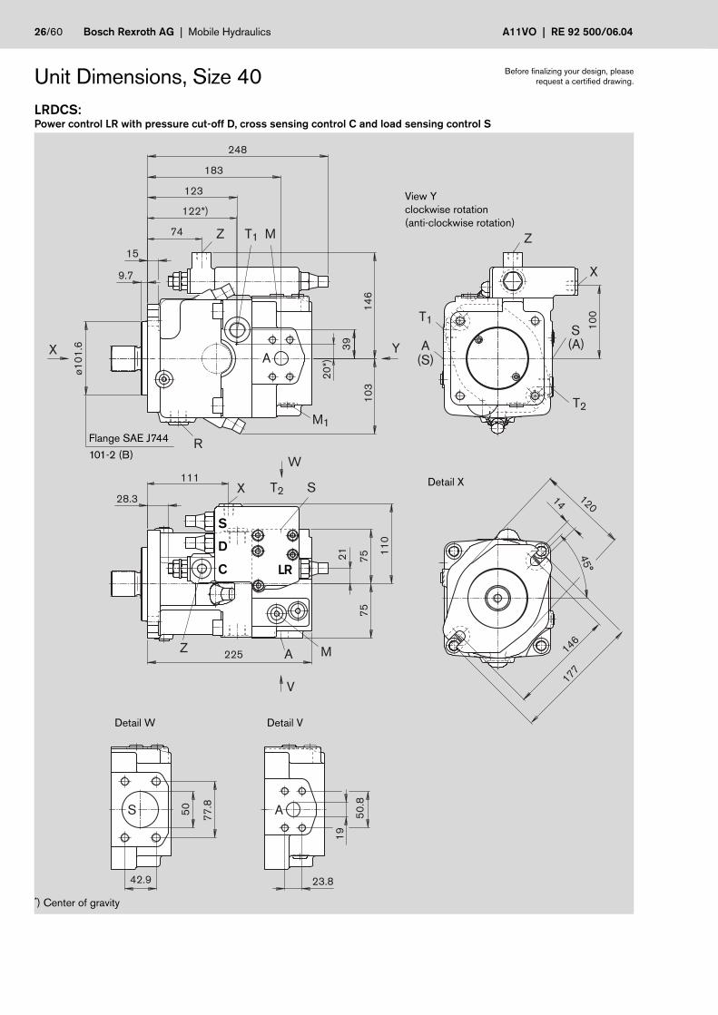
Unit Dimensions, Size 40LRDCS:Power control LR with pressure cut-off D, cross sensing control C and load sensing control S
View Yclockwise rotation(anti-clockwise rotation)
Detail X
Detail W
Flange SAE J744
101-2 (B)
Detail V
Before finalizing your design, pleaserequest a certified drawing.
S
D
C LR
*) Center of gravity

RE 92 500/06.04 | A11VO Mobile Hydraulics | Bosch Rexroth AG 27/60
9.5
M1
2x1
.75
1) 40
50
32
ø8
0.5
28
ø4
0
66
7.5
58
22
ø8
0.5 M
12
x1.7
5 1
)
ø3
2
ø4
0
9.5
ø8
0.5 7/1
6-1
4U
NC
-2B
28
48
56
40
ø4
0
7.5
30
ø8
0.5
22
ø4
03/8
-16
UN
C-2
B
38
46
P cyl. shaft with keyDIN 6885 – AS10x8x56
Shaft ends
T splined shaft1 1/4 in 14T 12/24DP 2)(SAE J744 – 32-4 (C))
S splined shaft1 in 15T 16/32DP 2)(SAE J744 – 25-4 (B-B))
Z splined shaft DIN 5480W35x2x30x16x9g
Unit Dimensions, Size 40 Before finalizing your design, pleaserequest a certified drawing.
PortsTightening torque, max.
A Service ports (high pressure series) SAE J518 3/4 in –Fastening thread DIN 13 M10x1.5; 17 deep see safety instructions
S Suction port (standard series) SAE J518 2 in –Fastening thread DIN 13 M12x1.75; 20 deep see safety instructions
T1, T2 Bleeding, tank DIN 3852 M22x1.5; 14 deep 210 Nm
R Bleeding, oil drain DIN 3852 M22x1.5; 14 deep 210 Nm
M1 Measuring position, positioning chamber DIN 3852 M12x1.5; 12 deep 50 Nm
M Measuring position, service port DIN 3852 M12x1.5; 12 deep 50 Nm
X Pilot pressure port DIN 3852 M14x1.5; 12 deep 80 Nmin version with load sensing (S)and remote controlled pressure cut-off (G)
Y Pilot pressure port DIN 3852 M14x1.5; 12 deep 80 Nmin version with stroke limiter (H...),2-stage pressure cut-off (E) and HD
Z Pilot pressure port DIN 3852 M14x1.5; 12 deep 80 Nmin version with cross sensing (C) andpower override (LR3, LG1)
G Port for control pressure (controller) DIN 3852 M14x1.5; 12 deep 80 Nmin version with stroke limiter (H.., U2),HD and EP with screw union GE10 - PLM(otherwise port G plugged)
1) Centering bore in accordance with DIN 3322) ANSI B92.1a-1976, 30° pressure angle, flat root side fit, tolerance class 5
28/60 Bosch Rexroth AG | Mobile Hydraulics A11VO | RE 92 500/06.04
Y
Y
78
248
206
58
5.5
15
3
21
10
613
1
G
206
60
10
613
12
1
78
15
3
248
21.5 GY
Y
G
206
10
6 15
3
29
248
78
Z
Z
X
228
1112
1
290
52
14
0
11
0
Y
Y
Z
Z
70.5
10
7.5
56 2
1
13
11
15
248
35
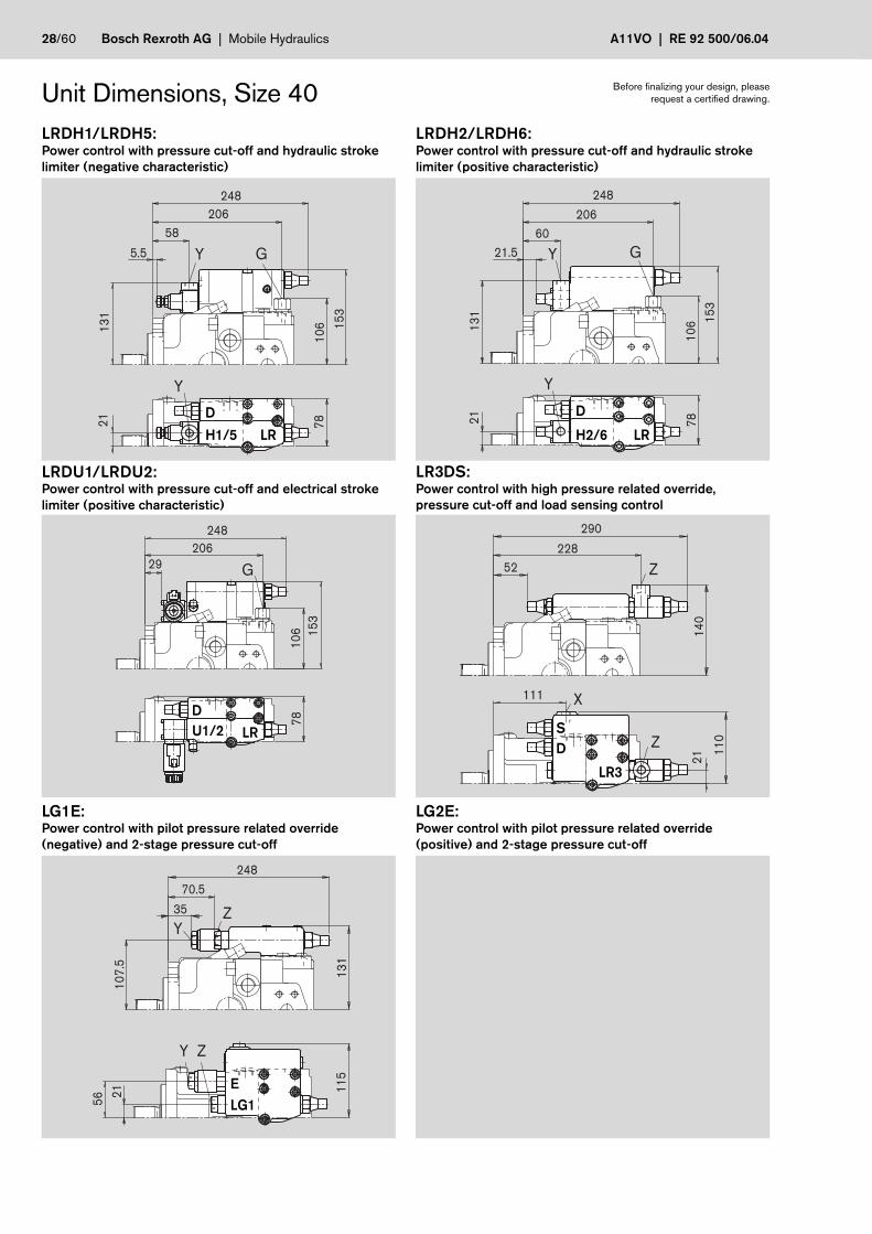
Unit Dimensions, Size 40
LG1E:Power control with pilot pressure related override(negative) and 2-stage pressure cut-off
LRDU1/LRDU2:Power control with pressure cut-off and electrical strokelimiter (positive characteristic)
LRDH1/LRDH5:Power control with pressure cut-off and hydraulic strokelimiter (negative characteristic)
LRDH2/LRDH6:Power control with pressure cut-off and hydraulic strokelimiter (positive characteristic)
LG2E:Power control with pilot pressure related override(positive) and 2-stage pressure cut-off
Before finalizing your design, pleaserequest a certified drawing.
LR3DS:Power control with high pressure related override,pressure cut-off and load sensing control
DH1/5 LR
D
H2/6 LR
DU1/2 LR S
D
LR3
ELG1

RE 92 500/06.04 | A11VO Mobile Hydraulics | Bosch Rexroth AG 29/60
10
6
206
62
21
78
13
4
208
23 Y
Y
GG
206
10
6 15
0.5
78
208
33
X111
11
01
34
209
52
X111
11
01
41
.5
248
25.5
X74
75 81
13
5
211.5
3
Unit Dimensions, Size 40EP1D/EP2D:Electrical control with proportional solenoid and pressurecut-off
HD1D/HD2D:Hydraulic control, pilot pressure related with pressurecut-off
DRS/DRG:Pressure control with load sensing controlPressure control remote controlled
Before finalizing your design, pleaserequest a certified drawing.
DRL:Pressure control for parallel operation
LE1S/LE2S:Power control with electrical override (negative) and loadsensing control
LE2S2/LE1S5/LE2S5:Power control with electrical override (negative) and loadsensing control, override
DHD1/2
D
EP1/2
S/GDR
S
DRL
LE1/2

30/60 Bosch Rexroth AG | Mobile Hydraulics A11VO | RE 92 500/06.04
Z T1 A M
Z
X
S(A)
T2
A
(S)
T1
S A
A
Z T1
R
M1
M
X T2 S
23
124.5
15
*)
140*)
88
41.5
11
11
54
11
2
82
82
17
10*)
50
.8
19
242
261,5
ø1
27
198
136
12.7
46
213
181
42.9 23.8
77
.8
50
19
Y
W
V
10
8
Unit Dimensions, Size 60
Flange SAE J744
127-2 (C)
LRDCS:Power control LR with pressure cut-off D, cross sensing control C and load sensing control S
Before finalizing your design, pleaserequest a certified drawing.
S
D
C LR
*) Center of gravity
View Yclockwise rotation(anti-clockwise rotation)
Detail W Detail V

RE 92 500/06.04 | A11VO Mobile Hydraulics | Bosch Rexroth AG 31/60
M1
2x1
.75
1)
ø9
1
40
50
28
32
9.5
ø4
5
ø3
5
M1
2x1
.75
1)
ø9
1
66
28
58
ø4
5
9.5
7/1
6-1
4U
NC
-2B
ø9
1
48
28
ø4
5
40
9.5
56
7/1
6-1
4U
NC
-2B
ø9
1
48
28
ø4
5
40
9.5
56
P cyl. shaft with keyDIN 6885 – AS10x8x56
Shaft ends
T splined shaft1 3/8 in 21T 16/32DP 2)
S splined shaft1 1/4 in 14T 12/24DP 2)(SAE J744 – 32-4 (C))
Z splined shaft DIN 5480W35x2x30x16x9g
Unit Dimensions, Size 60 Before finalizing your design, pleaserequest a certified drawing.
PortsTightening torque, max.
A Service ports (high pressure series) SAE J518 3/4 in –Fastening thread DIN 13 M10x1.5; 17 deep see safety instructions
S Suction port (standard series) SAE J518 2 in –Fastening thread DIN 13 M12x1.75; 20 deep see safety instructions
T1, T2 Bleeding, tank DIN 3852 M22x1.5; 14 deep 210 Nm
R Bleeding, oil drain DIN 3852 M22x1.5; 14 deep 210 Nm
M1 Measuring position, positioning chamber DIN 3852 M12x1.5; 12 deep 50 Nm
M Measuring position, service port DIN 3852 M12x1.5; 12 deep 50 Nm
X Pilot pressure port DIN 3852 M14x1.5; 12 deep 80 Nmin version with load sensing (S)and remote controlled pressure cut-off (G)
Y Pilot pressure port DIN 3852 M14x1.5; 12 deep 80 Nmin version with stroke limiter (H...),2-stage pressure cut-off (E) and HD
Z Pilot pressure port DIN 3852 M14x1.5; 12 deep 80 Nmin version with cross sensing (C) andpower override (LR3, LG1)
G Port for control pressure (controller) DIN 3852 M14x1.5; 12 deep 80 Nmin version with stroke limiter (H.., U2),HD and EP with screw union GE10 - PLM(otherwise port G plugged)
1) Centering bore in accordance with DIN 3322) ANSI B92.1a-1976, 30° pressure angle, flat root side fit, tolerance class 5

32/60 Bosch Rexroth AG | Mobile Hydraulics A11VO | RE 92 500/06.04
83
225
73.5
13
92
3
11
0.5 16
1
261.5
17
Y
GY
225
13
92
3
83
73.5
11
0.5 1
61
261.5
35
Y
GY
241
124.52
3 11
2
14
8
312
65.5
X
Z
Z
58 2
3
83.5
11
4
11
71
36
261,5
48
Y
Y
Z
Z
G
225
2.5
261.5
11
0.5
83
16
1
Unit Dimensions, Size 60
LG1E:Power control with pilot pressure related override(negative) and 2-stage pressure cut-off
LRDU1/LRDU2:Power control with pressure cut-off and electrical strokelimiter (positive characteristic)
LRDH1/LRDH5:Power control with pressure cut-off and hydraulic strokelimiter (negative characteristic)
LRDH2/LRDH6:Power control with pressure cut-off and hydraulic strokelimiter (positive characteristic)
LG2E:Power control with pilot pressure related override(positive) and 2-stage pressure cut-off
Before finalizing your design, pleaserequest a certified drawing.
LR3DS:Power control with high pressure related override,pressure cut-off and load sensing control
DH1/5 LR
DH2/6 LR
D
LR
SD
LR3
ELG1
U1/2

RE 92 500/06.04 | A11VO Mobile Hydraulics | Bosch Rexroth AG 33/60
83
11
0.5
23
225
75.5
13
9
221.5
38 Y G
Y
G
11
0.5
225
83
15
8.5
221.5
5.5
66.5
13
8.5
223.5
11
2
125.5 X X
76
.5
87.5
83
13
7
225
10.5
X124.5
15
0
261.5
11
2
39
Unit Dimensions, Size 60EP1D/EP2D:Electrical control with proportional solenoid and pressurecut-off
HD1D/HD2D:Hydraulic control, pilot pressure related with pressurecut-off
DRS/DRG:Pressure control with load sensing controlPressure control remote controlled
Before finalizing your design, pleaserequest a certified drawing.
DRL:Pressure control for parallel operation
LE1S/LE2S:Power control with electrical override (negative) and loadsensing control
LE2S2/LE1S5/LE2S5:Power control with electrical override (negative) and loadsensing control, override
DHD1/2
D
S/G
DR
S
DRL
LE1/2
EP1/2

34/60 Bosch Rexroth AG | Mobile Hydraulics A11VO | RE 92 500/06.04
Z
X
S(A)
T2
(S)A
T1
Z
T1 A
A
A
M
X T2 S
S
R M1
Z T1 M10*)
63
24
.5
138.5
130*)
105
56
10
*)
28
57
.2
25
16
0
21
200
162
88
.9
50.8
11
3.5
88
.58
8.5
19
260
11
7
ø1
52
.4
276
215
148
12.7
50
Y
W
V
11
7
*) Center of gravity
Unit Dimensions, Size 75
Flange SAE J744
152-4 (D)
LRDCS:Power control LR with pressure cut-off D, cross sensing control C and load sensing control S
Before finalizing your design, pleaserequest a certified drawing.
S
D
C LR
View Yclockwise rotation(anti-clockwise rotation)
Detail W Detail V

RE 92 500/06.04 | A11VO Mobile Hydraulics | Bosch Rexroth AG 35/60
ø9
6
3712
M1
6x2
1)
45
36
ø4
5
55
ø9
6
9.5
40
ø4
57/1
6-1
4U
NC
-2B
48
56
28
ø9
6
9.5
40
ø4
57/1
6-1
4U
NC
-2B
48
56
28
ø4
0
M1
6x2
1)
90
12
36
ø9
6
ø4
5
82
Shaft ends
Unit Dimensions, Size 75 Before finalizing your design, pleaserequest a certified drawing.
PortsTightening torque, max.
A Service ports (high pressure series) SAE J518 1 in –Fastening thread DIN 13 M12x1.75; 17 deep see safety instructions
S Suction port SAE J518 2 1/2 in –Fastening thread DIN 13 M12x1.75; 17 deep see safety instructions
T1, T2 Bleeding, tank DIN 3852 M22x1.5; 14 deep 210 Nm
R Bleeding, oil drain DIN 3852 M22x1.5; 14 deep 210 Nm
M1 Measuring position, positioning chamber DIN 3852 M12x1.5; 12 deep 50 Nm
M Measuring position, service port DIN 3852 M12x1.5; 12 deep 50 Nm
X Pilot pressure port DIN 3852 M14x1.5; 12 deep 80 Nmin version with load sensing (S)and remote controlled pressure cut-off (G)
Y Pilot pressure port DIN 3852 M14x1.5; 12 deep 80 Nmin version with stroke limiter (H...),2-stage pressure cut-off (E) and HD
Z Pilot pressure port DIN 3852 M14x1.5; 12 deep 80 Nmin version with cross sensing (C) andpower override (LR3, LG1)
G Port for control pressure (controller) DIN 3852 M14x1.5; 12 deep 80 Nmin version with stroke limiter (H.., U2),HD and EP with screw union GE10 - PLM(otherwise port G plugged)
P cyl. shaft with keyDIN 6885 – AS12x8x80
T splined shaft1 3/8 in 21T 16/32DP 2)
S splined shaft1 1/4 in 14T 12/24DP 2)(SAE J744 – 32-4 (C))
Z splined shaft DIN 5480W40x2x30x18x9g
1) Centering bore in accordance with DIN 3322) ANSI B92.1a-1976, 30° pressure angle, flat root side fit, tolerance class 5
36/60 Bosch Rexroth AG | Mobile Hydraulics A11VO | RE 92 500/06.04
Y
Y
G
24
.51
45
.5
239
87.5
10
98
9.5
16
7.5
276
31 Y
Y
G
10
9
24
.5
239
87.5
14
5.5
89
.5
16
7.5
276
49
G
239
10
98
9.5
16
7.5
276
15 Z
Z
X138.5
255.5
24
.5
11
3.5
15
4.5
326.5
80
Y
Y Z
Z
12
0.5
59
.5
24
.5
97.5
276
62
14
2.5
11
8.5
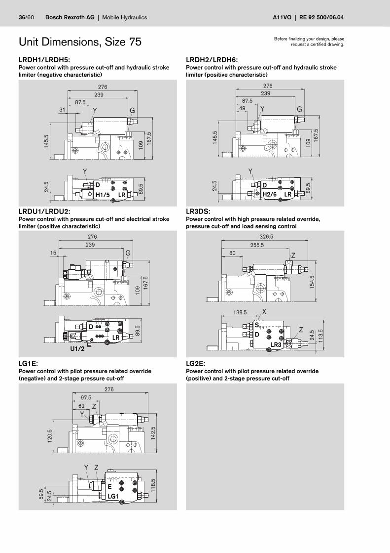
Unit Dimensions, Size 75
LG1E:Power control with pilot pressure related override(negative) and 2-stage pressure cut-off
LRDU1/LRDU2:Power control with pressure cut-off and electrical strokelimiter (positive characteristic)
LRDH1/LRDH5:Power control with pressure cut-off and hydraulic strokelimiter (negative characteristic)
LRDH2/LRDH6:Power control with pressure cut-off and hydraulic strokelimiter (positive characteristic)
LG2E:Power control with pilot pressure related override(positive) and 2-stage pressure cut-off
Before finalizing your design, pleaserequest a certified drawing.
LR3DS:Power control with high pressure related override,pressure cut-off and load sensing control
DH1/5 LR
DH2/6 LR
D
LR
SD
LR3
ELG1
U1/2

RE 92 500/06.04 | A11VO Mobile Hydraulics | Bosch Rexroth AG 37/60
Y G
Y1
09
24
.5
239
89.5
89
.5
14
5.5
235.5
50.5
X138.5
11
3.5
14
2.5
238.5
80
G
239
10
98
9.5
16
5
235.5
20.5
X
78
102.5
89
.5
240
14
4.5
25.5
X138.5
11
3.5
15
6.5
276
54
Unit Dimensions, Size 75EP1D/EP2D:Electrical control with proportional solenoid and pressurecut-off
HD1D/HD2D:Hydraulic control, pilot pressure related with pressurecut-off
DRS/DRG:Pressure control with load sensing controlPressure control remote controlled
Before finalizing your design, pleaserequest a certified drawing.
DRL:Pressure control for parallel operation
LE1S/LE2S:Power control with electrical override (negative) and loadsensing control
LE2S2/LE1S5/LE2S5:Power control with electrical override (negative) and loadsensing control, override
DHD1/2
D
S/G
DR
S
DRL
LE1/2
EP1/2

38/60 Bosch Rexroth AG | Mobile Hydraulics A11VO | RE 92 500/06.04
ZZ
X
XZ
T1
M
M
T2
T1
M
R
T2
S
(A)
A
(S)
M1
A
A
S
T1
ø1
30
ø1
01
287
16
10
ø4
09
.58
1)
ø3
85
ø4
28
.62
1)
ø4
51
ø11
12x30°
15°
13
9
10*)
26
150
10
*)
142*)
48
113
61.9
10
6.5
75
57
.2
25
27.8
161.6
200
17
2.5
12
5
ø1
52
.4
12.7
155
234
292
50
20
287
11
59
67
7
Y
W
V
A
S
Unit Dimensions, Size 95LRDCS:Power control LR with pressure cut-off D, cross sensing control C and load sensing control S
Before finalizing your design, pleaserequest a certified drawing.
Flange SAE
J744 152-4 (D)
Flange SAE 3 (G)
1) Dimensions according to SAE J617-No. 3, for connection to the flywheel housing of the combustion engine*) Center of gravity
S
D
C LR
View Yclockwise rotation(anti-clockwise rotation)
Detail W Detail V

RE 92 500/06.04 | A11VO Mobile Hydraulics | Bosch Rexroth AG 39/60
12
ø1
01
50
60
36
ø5
5
M1
6x2
1) 42
12
ø1
01
ø5
5
55
67
36
75
5/8
-11
UN
C-2
B
ø4
5
82
90
36
M1
6x2
1)
ø1
01
ø5
5
12
P cyl. shaft with keyDIN 6885 – AS14x9x80
Shaft ends
S splined shaft1 3/4 in 13T 8/16DP 2)(SAE J744 – 44-4 (D))
Z splined shaft DIN 5480W45x2x30x21x9g
Unit Dimensions, Size 95 Before finalizing your design, pleaserequest a certified drawing.
PortsTightening torque, max.
A Service ports (high pressure series) SAE J518 1 in –Fastening thread DIN 13 M12x1.75; 17 deep see safety instructions
S Suction port (standard series) SAE J518 3 in –Fastening thread DIN 13 M16x2; 24 deep see safety instructions
T1, T2 Bleeding, tank DIN 3852 M26x1.5; 16 deep 230 Nm
R Bleeding, oil drain DIN 3852 M26x1.5; 16 deep 230 Nm
M1 Measuring position, positioning chamber DIN 3852 M12x1.5; 12 deep 50 Nm
M Measuring position, service port DIN 3852 M12x1.5; 12 deep 50 Nm
X Pilot pressure port DIN 3852 M14x1.5; 12 deep 80 Nmin version with load sensing (S)and remote controlled pressure cut-off (G)
Y Pilot pressure port DIN 3852 M14x1.5; 12 deep 80 Nmin version with stroke limiter (H...),2-stage pressure cut-off (E) and HD
Z Pilot pressure port DIN 3852 M14x1.5; 12 deep 80 Nmin version with cross sensing (C) andpower override (LR3, LG1)
G Port for control pressure (controller) DIN 3852 M14x1.5; 12 deep 80 Nmin version with stroke limiter (H.., U2),HD and EP with screw union GE10 - PLM(otherwise port G plugged)
1) Centering bore in accordance with DIN 3322) ANSI B92.1a-1976, 30° pressure angle, flat root side fit, tolerance class 5

40/60 Bosch Rexroth AG | Mobile Hydraulics A11VO | RE 92 500/06.04
Y
Y
G
15
52
6
11
5
262
97.5
97
18
0
292
Y
Y
G
26
262
15
5
97.5
11
59
7
18
0
292
58.5
Y
Y
Z
Z
61 2
61
32
.5
108.5
12
0
292
73
15
7
G
18
0
11
5
262
97
292
32
X
Z
Z
11
5
26
1501
66
342.5
271.5
91
Unit Dimensions, Size 95
LG1E:Power control with pilot pressure related override(negative) and 2-stage pressure cut-off
LRDU1/LRDU2:Power control with pressure cut-off and electrical strokelimiter (positive characteristic)
LRDH1/LRDH5:Power control with pressure cut-off and hydraulic strokelimiter (negative characteristic)
LRDH2/LRDH6:Power control with pressure cut-off and hydraulic strokelimiter (positive characteristic)
LG2E:Power control with pilot pressure related override(positive) and 2-stage pressure cut-off
Before finalizing your design, pleaserequest a certified drawing.
LR3DS:Power control with high pressure related override,pressure cut-off and load sensing control
DH1/5 LR
DH2/6 LR
D
LR
SD
LR3
ELG1
U1/2
RE 92 500/06.04 | A11VO Mobile Hydraulics | Bosch Rexroth AG 41/60
X113.5
79
.5 97
15
3
255
36.5
X233
293
62.5
12
11
69
.5
262
252
31.5
17
4.9
11
4.8
97
GY
Y
G
26
11
5
262
101
97
15
5
252
62
150
11
51
57
255
91
X
X233 110
293
62.5
12
11
69
.5
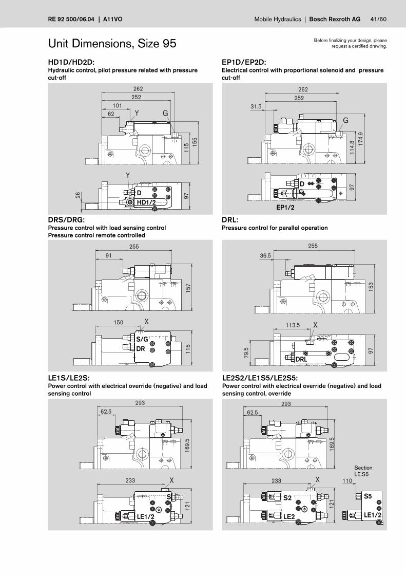
Unit Dimensions, Size 95EP1D/EP2D:Electrical control with proportional solenoid and pressurecut-off
HD1D/HD2D:Hydraulic control, pilot pressure related with pressurecut-off
DRS/DRG:Pressure control with load sensing controlPressure control remote controlled
Before finalizing your design, pleaserequest a certified drawing.
DRL:Pressure control for parallel operation
LE1S/LE2S:Power control with electrical override (negative) and loadsensing control
LE2S2/LE1S5/LE2S5:Power control with electrical override (negative) and loadsensing control, override
DHD1/2
D
S/GDR
LE1/2
DRL
EP1/2
S2
LE2
S5
LE1/2
SectionLE.S5
S

42/60 Bosch Rexroth AG | Mobile Hydraulics A11VO | RE 92 500/06.04
A1S1
XZ
S
(A)
T2
T1
A
(S)
Z
Z T1 A
S A
A
M
X T2 S
R
M1
T1
M
15°12x30°
ø11
310 358 358
75
10
6.4
61.9 31.8
66
.7
32
287 244
14
8
29
10*)
18
1.5
13
5
134
21
10
*)
170*)
57
.2
25
27.8
310
ø3
85
305 (A11VO) / 353 (A11VLO) 2)
ø4
28
.62
1)
ø4
51
ø4
09
.58
1)
16
10
ø1
06
ø1
30
255
61.9
10
6.4
75
313
255
174
12.7
204
161.6
21
ø1
52
.4
10
4
171
69
10
4
11
85
8Y
W
V
310
Unit Dimensions, Size 130/145
Flange SAE J744
152-4 (D)
LRDCS:Power control LR with pressure cut-off D, cross sensing control C and load sensing control S
Before finalizing your design, pleaserequest a certified drawing.
without charge pumpDetail W
Flange SAE 3 (G)
1) Dimensions according to SAE J617-No. 3, for connection to the flywheel housing of the combustion engine2) The housing or length dimension with flange SAE 3 is 5 mm shorter than the standard housing.*) Center of gravity
with charge pumpDetail W
SDC LR
View Yclockwise rotation(anti-clockwise rotation)
Detail V Detail V

RE 92 500/06.04 | A11VO Mobile Hydraulics | Bosch Rexroth AG 43/60
12
44
M1
6x2
1)
ø1
07
ø6
055
65
36
12
5/8
-11
UN
C-2
B
55
ø1
07
36
67
75
ø6
0
ø5
0
ø1
07 M
16
x2 1
)
12
82
ø6
0
90
36
P cyl. shaft with key DIN6885 – AS14x9x80
Shaft ends
S splined shaft1 3/4 in 13T 8/16DP 2)(SAE J744 – 44-4 (D))
Z splined shaft DIN 5480W50x2x30x24x9g
Unit Dimensions, Size 130/145 Before finalizing your design, pleaserequest a certified drawing.
PortsTightening torque, max.
A Service ports (high pressure series) SAE J518 1 in –Fastening thread DIN 13 M12x1.75; 17 deep see safety instructions
A1 Service ports (high pressure series) with charge pump SAE J518 1 1/4 in –Fastening thread DIN 13 M14x2; 19 deep see safety instructions
S, S1 Suction port (standard series) SAE J518 3 in –Fastening thread DIN 13 M16x2; 24 deep see safety instructions
T1, T2 Bleeding, tank DIN 3852 M26x1.5; 16 deep 230 Nm
R Bleeding, oil drain DIN 3852 M26x1.5; 16 deep 230 Nm
M1 Measuring position, positioning chamber DIN 3852 M12x1.5; 12 deep 50 Nm
M Measuring position, service port DIN 3852 M12x1.5; 12 deep 50 Nm
X Pilot pressure port DIN 3852 M14x1.5; 12 deep 80 Nmin version with load sensing (S)and remote controlled pressure cut-off (G)
Y Pilot pressure port DIN 3852 M14x1.5; 12 deep 80 Nmin version with stroke limiter (H...),2-stage pressure cut-off (E) and HD
Z Pilot pressure port DIN 3852 M14x1.5; 12 deep 80 Nmin version with cross sensing (C) andpower override (LR3, LG1)
G Port for control pressure (controller) DIN 3852 M14x1.5; 12 deep 80 Nmin version with stroke limiter (H.., U2),HD and EP with screw union GE10 - PLM(otherwise port G plugged)
1) Centering bore in accordance with DIN 3322) ANSI B92.1a-1976, 30° pressure angle, flat root side fit, tolerance class 5

44/60 Bosch Rexroth AG | Mobile Hydraulics A11VO | RE 92 500/06.04
10
5
28
16
4 18
9
11
5
313283
118.5
Y
G
Y
18
9
11
5
313
283
48
10
5
G
Y Z
Y Z
12
3
63 2
8
16
6
313
129.5
94
10
5
Y
Y
G
283
118.5
16
4
11
5
28
18
9
313
79.5
X
Z
Z
1712
8
293
11
8
17
5.5
364
112
Unit Dimensions, Size 130/145
LG1E:Power control with pilot pressure related override(negative) and 2-stage pressure cut-off
LRDU1/LRDU2:Power control with pressure cut-off and electrical strokelimiter (positive characteristic)
LRDH1/LRDH5:Power control with pressure cut-off and hydraulic strokelimiter (negative characteristic)
LRDH2/LRDH6:Power control with pressure cut-off and hydraulic strokelimiter (positive characteristic)
LG2E:Power control with pilot pressure related override(positive) and 2-stage pressure cut-off
Before finalizing your design, pleaserequest a certified drawing.
LR3DS:Power control with high pressure related override,pressure cut-off and load sensing control
DDH2/6 LR
DLR
SD
LR3
ELG1
U1/2
H1/5
LR

RE 92 500/06.04 | A11VO Mobile Hydraulics | Bosch Rexroth AG 45/60
283
273
125
16
4
28
10
51
15
86 Y
G
Y
18
4
11
5
283
273
10
5
52.5
G
171
11
81
66
276
112
X134.5
82
.5 10
5
276
16
2
57.5
X
316
17
8.5
83.5
12
4
254 X
316
17
8.5
83.5
12
4
254 131X
Unit Dimensions, Size 130/145EP1D/EP2D:Electrical control with proportional solenoid and pressurecut-off
HD1D/HD2D:Hydraulic control, pilot pressure related with pressurecut-off
DRS/DRG:Pressure control with load sensing controlPressure control remote controlled
Before finalizing your design, pleaserequest a certified drawing.
DRL:Pressure control for parallel operation
LE1S/LE2S:Power control with electrical override (negative) and loadsensing control
LE2S2/ LE1S5/LE2S5:Power control with electrical override (negative) and loadsensing control, override
DHD1/2
D
S/GDR
DRL
EP1/2
S2
LE2
S5
LE1/2
SectionLE.S5
LE1/2
S

46/60 Bosch Rexroth AG | Mobile Hydraulics A11VO | RE 92 500/06.04
A1S1
Z
S A
ZX
T1
A
(S)
T2
(A)
S
M
A
ZX
T2 S
M1R
T1 M
ø1
26
ø4
51
ø4
09
.58
1)
ø1
55
ø3
85
341.8 (A11VO) / 390 (A11VLO) 2)
16
1012x 30°
15°
ø11
346.8346.8
281.3281.3 272
395395
319
69.9
12
0.7
90
79
.4
38
139.8
318.8
13
1
11
61
16
66
16
3.2
19
6
10
*)
170*)
379
ø1
65
.1
190.5
203.5
27
15.9
21
262.5
224.5
15
6
34
10*)
79
.4
38
36.5
12
0.7
90
69.9 36.5
ø4
28
.62
1)
Y
W
T1 A
V
346.8
Unit Dimensions, Size 190LRDCS:Power control LR with pressure cut-off D, cross sensing control C and load sensing control S
Before finalizing your design, pleaserequest a certified drawing.
Flange SAE J744
165-4 (E)
Flange SAE 3 (G)
1) Dimensions according to SAE J617-No. 3, for connection to the flywheel housing of the combustion engine2) The housing or length dimension with flange SAE 3 is 5 mm shorter than the standard housing.*) Center of gravity
SDCLR
without charge pumpDetail W
with charge pumpDetail W
View Yclockwise rotation(anti-clockwise rotation)
Detail V Detail V

RE 92 500/06.04 | A11VO Mobile Hydraulics | Bosch Rexroth AG 47/60
5/8
-11
UN
C-2
B
67
55
12
36
ø1
26
75
ø6
0
ø1
26 M
16
x2 1
) 4412
36
55
65
ø6
0
36
ø6
0
88
ø1
26
12
6680
5/8
-11
UN
C-2
B
ø5
5
113
M2
0x2
.5 1
)
42
15
ø1
26
105
ø6
0
P cyl. shaft with key DIN6885 – AS16x10x100
Shaft ends
S splined shaft1 3/4 in 13T 8/16DP 2)(SAE J744 – 44-4 (D))
Z splined shaft DIN 5480W50x2x30x24x9g
Unit Dimensions, Size 190 Before finalizing your design, pleaserequest a certified drawing.
PortsTightening torque, max.
A, A1 Service ports (high pressure series) SAE J518 1 1/2 in –Fastening thread DIN 13 M16x2; 21 deep see safety instructions
S, S1 Suction port (standard series) SAE J518 3 1/2 in –Fastening thread DIN 13 M16x2; 24 deep see safety instructions
T1, T2 Bleeding, tank DIN 3852 M33x2; 18 deep 540 Nm
R Bleeding, oil drain DIN 3852 M33x2; 18 deep 540 Nm
M1 Measuring position, positioning chamber DIN 3852 M12x1.5; 12 deep 50 Nm
M Measuring position, service port DIN 3852 M12x1.5; 12 deep 50 Nm
X Pilot pressure port DIN 3852 M14x1.5; 12 deep 80 Nmin version with load sensing (S)and remote controlled pressure cut-off (G)
Y Pilot pressure port DIN 3852 M14x1.5; 12 deep 80 Nmin version with stroke limiter (H...),2-stage pressure cut-off (E) and HD
Z Pilot pressure port DIN 3852 M14x1.5; 12 deep 80 Nmin version with cross sensing (C) andpower override (LR3, LG1)
G Port for control pressure (controller) DIN 3852 M14x1.5; 12 deep 80 Nmin version with stroke limiter (H.., U2),HD and EP with screw union GE10 - PLM(otherwise port G plugged)
T splined shaft2 in 15T 8/16DP 2)(SAE J744 – 50-4 (F))
1) Centering bore in accordance with DIN 3322) ANSI B92.1a-1976, 30° pressure angle, flat root side fit, tolerance class 5
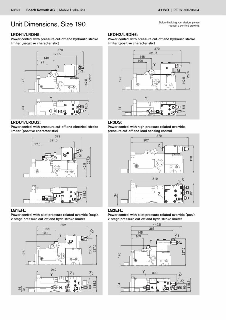
48/60 Bosch Rexroth AG | Mobile Hydraulics A11VO | RE 92 500/06.04
Y
Y
G
34
11
8.5
17
6
321.5
148
14
2.5 22
7.5
379
91Y
Y
G
34
11
8.5
321.5148
14
2.5
17
6 22
7.5
379
109
379
22
7.5
14
2.5
321.577.5
11
8.5
G
Z
X
Z
319
34 13
11
78
379
207
Z2Z1Y
YZ2
20
0.5
44
34
242
69
148
17
6
392
11
8.5
22
7.5
109
Y
Y
Z1
Z1
Z2
399
34
17
6
365148
69
22
7.5
11
8.5
442.5
109
DLR
DLR
Unit Dimensions, Size 190
LG1EH.:Power control with pilot pressure related override (neg.),2-stage pressure cut-off and hydr. stroke limiter
LRDU1/LRDU2:Power control with pressure cut-off and electrical strokelimiter (positive characteristic)
LRDH1/LRDH5:Power control with pressure cut-off and hydraulic strokelimiter (negative characteristic)
LRDH2/LRDH6:Power control with pressure cut-off and hydraulic strokelimiter (positive characteristic)
LG2EH.:Power control with pilot pressure related override (pos.),2-stage pressure cut-off and hydr. stroke limiter
Before finalizing your design, pleaserequest a certified drawing.
LR3DS:Power control with high pressure related override,pressure cut-off and load sensing control
DLR H2/6
SD
LR3
ELG1
U1/2
H1/5
H.E
LG2H.

RE 92 500/06.04 | A11VO Mobile Hydraulics | Bosch Rexroth AG 49/60
Y G
Y
379321.5
148109
11
8.5
17
8
18
3
14
2.5
34
11
8.5
18
7.5
14
2.5
379
321.5
77.5 G
319
13
11
78
379
223
X X
89
.5
161.5
11
8.5
17
8
315.5
79.5
13
31
92
383
156.5
321.5 X 198.5
13
31
92
383
156.5
321.5 X
Unit Dimensions, Size 190EP1D/EP2D:Electrical control with proportional solenoid and pressurecut-off
HD1D/HD2D:Hydraulic control, pilot pressure related with pressurecut-off
DRS/DRG:Pressure control with load sensing controlPressure control remote controlled
Before finalizing your design, pleaserequest a certified drawing.
DRL:Pressure control for parallel operation
LE1S/LE2S:Power control with electrical override (negative) and loadsensing control
LE2S2/LE1S5/LE2S5:Power control with electrical override (negative) and loadsensing control, override
D D
LE1/2
DRL
EP1/2HD1/2
S
S/GDR
S2
LE2
SectionLE.S5
LE1/2S5

50/60 Bosch Rexroth AG | Mobile Hydraulics A11VO | RE 92 500/06.04
346 329.5
428428372.1372.1
307 307
79
.4
38
36.5
13
0.2
10
0
77.869.9
12
0.7
90
36.5
79
.4
38
13
0
13
7
13
0
166.5
346
A1S1AS
T1Z M
M1R
30
185*)
10
*)
17
6.2
20
5.5
72
408,5
214
15.9
ø1
65
.1
Y
XZ
T1
A
(S)
R
T2
S
(A)
21
15
6
34
10*)
262.5
224.5
T1
M
ST2
A
A
Z X
W
V
372.1
Unit Dimensions, Size 260LRDCS:Power control LR with pressure cut-off D, cross sensing control C and load sensing control S
Before finalizing your design, pleaserequest a certified drawing.
Flange SAE J744
165-4 (E)
SDCLR
*) Center of gravity
without charge pumpDetail W
with charge pumpDetail W
View Yclockwise rotation(anti-clockwise rotation )
Detail V Detail V

RE 92 500/06.04 | A11VO Mobile Hydraulics | Bosch Rexroth AG 51/60
15
42
66
ø1
31
ø7
03/4
-10
UN
C-2
B 80
88
675512
75
36
ø1
31 5/8
-11
UN
C-2
B
ø7
0
42
584715
ø7
0
ø1
31 M
20
x2.5
2)
66
ø6
0
ø1
31 M
20
x2.5
2)
113
42
ø7
0
105
15
P cyl. shaft with keyDIN 6885 –AS18x11x100
Shaft ends
S splined shaft1 3/4 in 13T 8/16DP 2)(SAE J744 – 44-4 (D))
Z splined shaft DIN 5480W60x2x30x28x9g
Unit Dimensions, Size 260 Before finalizing your design, pleaserequest a certified drawing.
PortsTightening torque, max.
A, A1 Service ports (high pressure series) SAE J518 1 1/2 in –Fastening thread DIN 13 M16x2; 21 deep see safety instructions
S Suction port (standard series) SAE J518 3 1/2 in –Fastening thread DIN 13 M16x2; 21 deep see safety instructions
S1 Suction port (standard series) SAE J518 4 in –Fastening thread DIN 13 M16x1; 21 deep see safety instructions
T1, T2 Bleeding, tank DIN 3852 M33x2; 16 deep 540 Nm
R Bleeding, oil drain DIN 3852 M33x2; 16 deep 540 Nm
M1 Measuring position, positioning chamber DIN 3852 M12x1.5; 12 deep 50 Nm
M Measuring position, service port DIN 3852 M12x1.5; 12 deep 50 Nm
X Pilot pressure port DIN 3852 M14x1.5; 12 deep 80 Nmin version with load sensing (S)and remote controlled pressure cut-off (G)
Y Pilot pressure port DIN 3852 M14x1.5; 12 deep 80 Nmin version with stroke limiter (H...),2-stage pressure cut-off (E) and HD
Z Pilot pressure port DIN 3852 M14x1.5; 12 deep 80 Nmin version with cross sensing (C) andpower override (LR3, LG1)
G Port for control pressure (controller) DIN 3852 M14x1.5; 12 deep 80 Nmin version with stroke limiter (H.., U2),HD and EP with screw union GE10 - PLM(otherwise port G plugged)
T splined shaft2 1/4 in 17T 8/16DP 2)
1) Centering bore in accordance with DIN 3322) ANSI B92.1a-1976, 30° pressure angle, flat root side fit, tolerance class 5

52/60 Bosch Rexroth AG | Mobile Hydraulics A11VO | RE 92 500/06.04
408.5351
174.5116
23
91
53
18
7.5
40
13
2.5
G
Y
Y
18
7.5
13
2.5
40
23
91
53
408.5351
174.5135.5
G
Y
Y
408.5
23
91
32
.51
53
351104.5
G
40
345.5
13
7
18
9.5
408.5
235
X
Z
21
27
5
50
268.5
419.6
174.5135.5
23
9
18
7.5
40 1
32
.5
Y
Z2
Y
Z2
Z1
40
21
27
5
469.2
469.1391.6
174.5135.5
24
6
18
7.5
13
2.5
Y
Y
Z1
Z2Z1
Unit Dimensions, Size 260
LRDU1/LRDU2:Power control with pressure cut-off and electrical strokelimiter (positive characteristic)
LRDH1/LRDH5:Power control with pressure cut-off and hydraulic strokelimiter (negative characteristic)
LRDH2/LRDH6:Power control with pressure cut-off and hydraulic strokelimiter (positive characteristic)
Before finalizing your design, pleaserequest a certified drawing.
LR3DS:Power control with high pressure related override,pressure cut-off and load sensing control
LG1EH.:Power control with pilot pressure related override (neg.),2-stage pressure cut-off and hydr. stroke limiter
LG2EH.:Power control with pilot pressure related override (pos.),2-stage pressure cut-off and hydr. stroke limiter
DLR
DLR
DLR H2/6
SD
LR3U1/2
H1/5
ELG2H.
ELG1H.
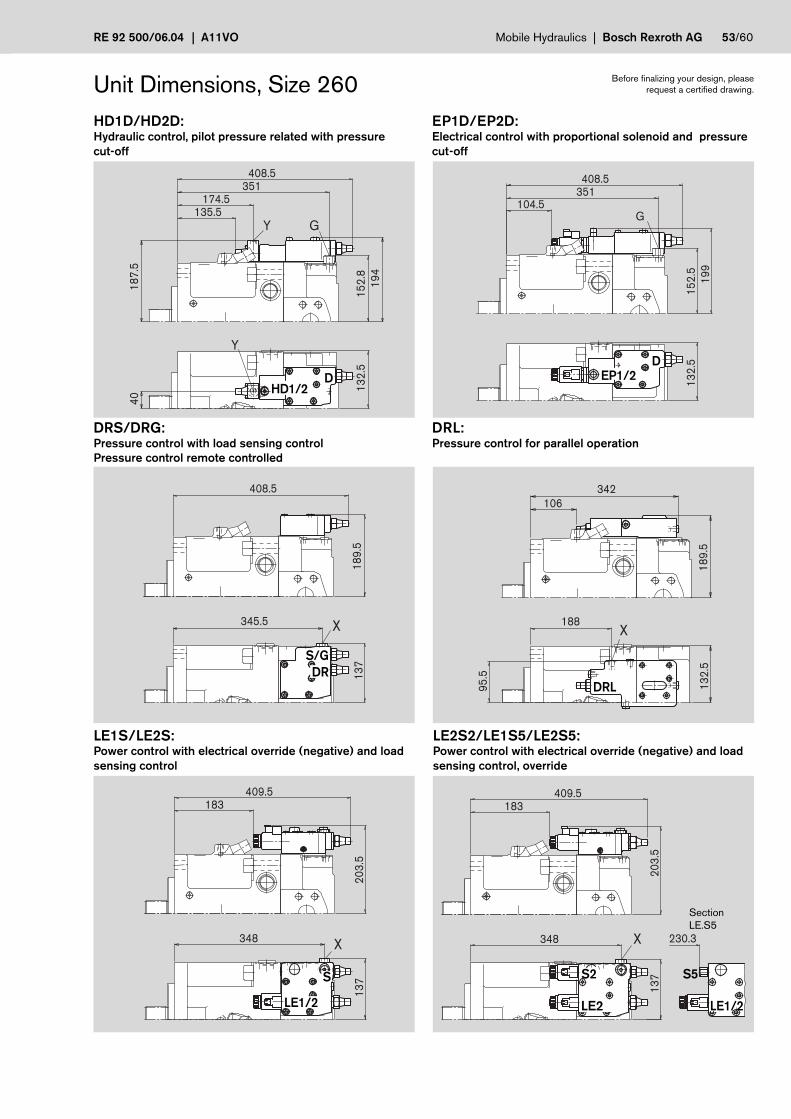
RE 92 500/06.04 | A11VO Mobile Hydraulics | Bosch Rexroth AG 53/60
18
7.5
40
13
2.5
15
2.8
19
4
408.5351
174.5135.5
G
Y
Y
13
2.5
19
9
15
2.5
408.5351
104.5G
345.5
13
7
408.5
18
9.5
X X188
95
.5
13
2.5
18
9.5
342
106
20
3.5
409.5183
13
7
348X
20
3.5
409.5183
13
7
348 230.3X
Unit Dimensions, Size 260EP1D/EP2D:Electrical control with proportional solenoid and pressurecut-off
HD1D/HD2D:Hydraulic control, pilot pressure related with pressurecut-off
DRS/DRG:Pressure control with load sensing controlPressure control remote controlled
Before finalizing your design, pleaserequest a certified drawing.
DRL:Pressure control for parallel operation
LE1S/LE2S:Power control with electrical override (negative) and loadsensing control
LE2S2/LE1S5/LE2S5:Power control with electrical override (negative) and loadsensing control, override
DD
LE1/2
DRL
EP1/2HD1/2
S
S/GDR
LE2
S2
LE1/2
S5
SectionLE.S5

54/60 Bosch Rexroth AG | Mobile Hydraulics A11VO | RE 92 500/06.04
A3
ø8
2.5
A2
130
106.4
2)
A3
181213
ø127
A2
2)
A3
ø146
45°
ø1
01
.6
A2
146
2)
Through Drive Dimensions Before finalizing your design, pleaserequest a certified drawing.
A1 A2 A3 3)Size K07 K24 K80 K6160 272 – 265 265 13 M16x2; 20 deep75 290 – 283 283 13 M16x2; 20 deep95 318 318 318 318 13 M16x2; 16 deep130/145 330 330 330 330 13 M16x2; 20 deep
130/145* 364 364 364 364 13 M16x2; 20 deep*) Version with charge pump
A1 A2 A3 3)Size K02 K04 K7940 244 244 10 M12x1.75; 19 deep60 261 261 265 10 M12x1.75; 19 deep75 279 279 10 M12x1.75; 19 deep95 303 303 303 10 M12x1.75; 16 deep130/145 326 326 326 10 M12x1.75; 16 deep130/145* 360 360 360 10 M12x1.75; 16 deep190 371.8 371.8 361.8 – M12x1.75; 15 deep190* 404 404 394 – M12x1.75; 15 deep260 395 395 395 – M12x1.75; 15 deep
260* 437.5 437.5 437.5 – M12x1.75; 15 deep*) Version with charge pump
Note: All through drive flanges can be turned 90°. Please state in clear text if required.1) Pressure angle 30°, flat root side fit, tolerance class 52) O-ring seal is included in the supply3) Thread according to DIN 13, see safety instructions
Flange SAE J744 – 82-2 (A) Coupler for splined shaft according 5/8in 9T 16/32DP 1) (SAE J744 – 16-4 (A)) K01to ANSI B92.1a-1976 3/4in 11T 16/32DP 1) (SAE J744 – 19-4 (A-B)) K52
A1up to mounting flange
Flange SAE J744 – 101-2 (B) Coupler for splined shaft according 7/8in 13T 16/32DP 1) (SAE J744 – 22-4 (B)) K02to ANSI B92.1a-1976 1in 15T 16/32DP 1) (SAE J744 – 25-4 (B-B)) K04Coupler for splined shaft accordingto DIN 5480 W35x2x30x16x9g K79
A1up to mounting flange
Flange SAE J744 – 127-2 (C) Coupler for splined shaft according 1 1/4in 14T 12/24DP 1) (SAE J744 – 32-4 (C)) K07to ANSI B92.1a-1976 1 1/2in 17T 12/24 DP 1) (SAE J744 – 38-4 (C-C)) K24Coupler for splined shaft according W30x2x30x14x9g K80to DIN 5480 W35x2x30x16x9g K61
A1up to mounting flange
A1 A2 A3 3)
Size K01 K5240 240 240 8 M10x1.5; 15 deep60 257 257 – M10x1.5; 15 deep75 275 275 – M10x1.5; 15 deep95 306 306 – M10x1.5; 12.5 deep130/145 339 329 – M10x1.5; 12.5 deep130/145* 373 363 – M10x1.5; 12.5 deep190 359.8 359.8 – M10x1.5; 13 deep190* 394 394 – M10x1.5; 13 deep260 385 385 – M10x1.5; 13 deep
260* 27.3 427.3 – M10x1.5; 13 deep*) Version with charge pump
In size 190 and 260 the hole template is turned 45° counterclockwise.
Hole template in size 40 to 145

RE 92 500/06.04 | A11VO Mobile Hydraulics | Bosch Rexroth AG 55/60
A3
145
A2
ø1
65
.1
14
5
ø27
0
2)
A3
ø1
52
.4
12
8
A2
128
2)
A3
115
ø127
A2
115181
2)
A1 A2 A3 3)Size K07 K24 K80 K61190 367.8 367.8 367.8 367.8 13 M16x2; 19 deep190* 400 400 400 400 13 M16x2; 19 deep260 391.5 391.5 391.5 391.5 13 M16x2; 19 deep
260* 433.5 433.5 433.5 433.5 13 M16x2; 19 deep*) Version with charge pump
Through Drive Dimensions Before finalizing your design, pleaserequest a certified drawing.
A1 A2 A3 3)Size K86 K17 K81 K82 K8375 290 – 290 – – 13 M20x2.5; 28 deep95 317 – 317 317 – 30 M20x2.5; 25 deep130/145 340 350 340 340 340 30 M20x2.5; 25 deep130/145* 374 384 374 374 374 30 M20x2.5; 25 deep190 392 392 392 392 392 13 M20x2.5; 22 deep190* 424 424 424 424 424 13 M20x2.5; 22 deep260 417 417 417 417 417 13 M20x2.5; 22 deep
260* 459 459 459 459 459 13 M20x2.5; 22 deep*) Version with charge pump
A1 A2 A3 3)Size K72 K84 K67190 376.8 376.8 – 19 M20x2.5; 20 deep190* 409 409 – 19 M20x2.5; 20 deep260 417 400 400 19 M20x2.5; 20 deep
260* 459 442.5 442.5 19 M20x2.5; 20 deep
*) Version with charge pump
A1up to mounting flange
A1up to mounting flange
Flange SAE J744 – 127-2 + 4 (C) Coupler for splined shaft according 1 1/4in 14T 12/24DP 1) (SAE J744 – 32-4 (C)) K07to ANSI B92.1a-1976 1 1/2in 17T 12/24 DP 1) (SAE J744 – 38-4 (C-C)) K24Coupler for splined shaft according W30x2x30x14x9g K80to DIN 5480 W35x2x30x16x9g K61
A1up to mounting flange
Flange SAE J744 – 152-4 (D) Coupler for splined shaft according 1 1/4in 14T 12/24DP 1) (SAE J744 – 32-4 (C)) K86to ANSI B92.1a-1976 1 3/4in 13T 8/16DP 1) (SAE J744 – 44-4 (D)) K17Coupler for splined shaft according W40x2x30x18x9g K81to DIN 5480 W45x2x30x21x9g K82
W50x2x30x24x9g K83
Flange SAE J744 – 101-2 (E) Coupler for splined shaft according 13/4 in 13T 16/32 DP 1) (SAE J744 – 32-4 (C)) K72to ANSI B92.1a-1976Coupler for splined shaft according W50x2x30x24x9g K84to DIN 5480 W60x2x30x28x9g K67
Note: All through drive flanges can be turned 90°. Please state in clear text if required.1) 30° pressure angle, flat root side fit, tolerance class 52) O-ring seal is included in the supply3) Thread according to DIN 13, see safety instructions

56/60 Bosch Rexroth AG | Mobile Hydraulics A11VO | RE 92 500/06.04
A
FlangeHub
A11VO(2nd pump)
A11VO(1st pump)
Summary of Through Drive Assembly Possibilites for A11V(L)OThrough drive – A11VO attachment – 2nd pump through drive
Flange coupler for A11VO A10V(S)O/31 A10V(S)O/52 A4FO A4VG A10VG external gear- availablesplined shaft code Size (shaft) Size (shaft) Size (shaft) Size (shaft) Size (shaft) Size (shaft) pump for Size
82-2 (A) 5/8in K01 — 18 (U) 10 (U) — — — frame size F 40...260size 4-22 1)
3/4in K52 — 18 (S) 10 (S) — — — — 40...260
101-2 (B) 7/8in K02 — 28 (S,R) 28 (S,R) 16, 22, 28 (S) — 18 (S) frame size N 40...26045 (U) 45 (U,W) size 20-32 1)
frame size Gsize 38-45 1)
1in K04 40 (S) 45 (S,R) 45 (S,R) — 28 (S) 28, 45 (S) — 40...26060 (U,W)
W35 K79 40 (Z) — — — — — — 40...260
127-2 (C) 1 1/4in K07 60 (S) 71 (S,R) 60 (S) 2) — 40, 56, 71 (S) 63 (S) — 60...260100 (U) 85 (U)
1 1/2in K24 — 100 (S) 85 (S) — — — — 95...260
W30 K80 – – – – 40, 56 (Z) – – 60...260
W35 K61 60 (Z) — — — 40, 56 (A) — — 60...26071 (Z)
152-4 (D) 1 1/4in K86 75 (S) — — — — — — 75...260
1 3/4in K17 95, 130, 145 (S) 140 (S) — — 90, 125 (S) — — 130...260
W40 K81 75 (Z) — — — 125 (Z) — — 75...260
W45 K82 95 (Z) — — — 90, 125 (A) — — 95...260
W50 K83 130, 145 (Z) — — — — — — 130...260
165-4 (E) 1 3/4in K72 190, 260 (S) — — — 180, 250 (S) — — 190...260
W50 K84 190 (Z) — — — 180 (Z) — — 190...260
W60 K67 260 (Z) — — — — — — 2601) Rexroth recommends special versions of the gear pumps. Please ask.2) Only A10VO with 4-hole mounting flange can be mounted to A11V(L)O 190 and 260.
When ordering combination pumps, the type designations of the 1st and 2ndpumps must be connected by a "+".
Ordering code 1st pump + Ordering code 2nd pump
Ordering example:
A11VO130LRDS/10R-NZD12K61 + A11VO60LRDS/10R-NZC12N00
Note:For permissible input torques and though drive torques see page 7, technical data.
Combination Pumps A11VO + A11VOTotal length A 1)
A11VO A11VO (2nd pump)
(1st pump) size 40 size 60 size 75 size 95 size 130/145 size 130/145 2) size 190 size 190 2) size 260 size 260 2)
size 40 — — — — — — — — —
size 60 490 507 — — — — — — — —
size 75 525 550 — — — — — — —
size 95 528 560 577 604 — — — — — —
size 130/145 551 572 600 627 650 698 — — — —
size 130/145 2) 585 606 634 661 684 732 — — — —
size 190 586.8 609.8 652 679 702 750 723.6 772.3 — —
size 190 2) 619 642 684 711 734 782 755.8 804.5 — —
size 260 620 633.5 677 704 727 775 746.8 795.5 772 828
size 260 2) 662.5 675.5 719 746 769 817 789.3 838 814.5 870.51) When using the S shaft (splined shaft DIN 5480) for the attached pump (2nd pump)2) Version with charge pump

RE 92 500/06.04 | A11VO Mobile Hydraulics | Bosch Rexroth AG 57/60
V
C
BA
Ua
Vg max Vg min
M1 ST2R
Vg max Vg min
M1 ST2RVg max
Vg min
0
1
C
A
Swivel Angle IndicatorOptical swivel angle indicator, VWith the optical swivel angle indicator, a mechanical pointer onthe side of the pump housing displays the position of theswivel angle of the pump.
size A C
40 50.5 84.0
60 not available
75 60.7 97.0
95 63.5 104.0
130 70.9 112.0
190 87.6 123.5
260 87.6 137.0
Electrical swivel angle sensor, RWith the electrical swivel angle indicator the swivel position ofthe pump is measured by an electrical swivel angle sensor. Ithas a robust, sealed housing and integrated electronicsdesigned for automotive applications.
As an output the Hall effect swivel angle sensor supplies avoltage signal proportional to the swivel angle (see technicalparameters).
Parameters
Supply voltage Ub 10...30 V DCCurrent consumption < 15 mA
Output voltage Ua 2.5 V (Vg min)...4.5 V (Vg max)
Load resistance ≥ 20 kΩReverse polarity protection Supply voltage to groundProtection against short circuit of the signal to groundEMC - DIN 40839EN 55025, ISO/EN 14982, Details on requestISO 11452, ISO 7637-1Operating temperature range -40° C...+125° CVibration resistanceSinusoidal vibration EN 60068-2-6 4g / 22...500 Hz
Random vibration IEC 68-2-36 min. 0.02g2 / Hz
Shock resistance:
Continuous shocking IEC 68-2-29 10g / 15 ms
Type of protection DIN/EN 60529 IP67 and IP69K
Housing material synthetic material
Mating connector
Female connector AMP Superseal 1.5; 3-pin,Rexroth Mat. no. 2602132, consisting of: AMP-No.– 1 female connector housing, 3-pins ____________ 282087-1
– 3 single wire seal, yellow ____________________ 281934-2
– 3 female connector contacts 1.8 - 3.3 mm ______ 283025-1
The mating connector is not included in the supply. It can besupplied by Rexroth on request.
size A B C
40 50.5 88.5 118.360 not available75 60.7 98.7 131.395 63.5 101.5 138.3130 70.9 108.9 146.3190 87.6 125.6 157.8
260 87.6 125.6 171.3
Outputvoltage Ua
Detail Vnot to scale
Ub Ground

58/60 Bosch Rexroth AG | Mobile Hydraulics A11VO | RE 92 500/06.04
36
68,5
Ø3
7
50
50
Ø3
7
68,5
65
,4
Male Connector for SolenoidsDEUTSCH DT04-2P-EP04 (2-pole)moulded to the solenoid coil,without bidirectional surpressor diode ___________________ P
Type of protection according to DIN/EN 60529: IP67 and IP69K
Cablegland
Mating connector
Female connector DEUTSCH DT06-2S-EP04Rexroth Mat. no. 02601804
consisting of: DT designation
– 1 housing __________________________ DT06-2S-EP04
– 1 wedge ___________________________ W2S
– 2 female connectors _________________ 0462-201-16141The mating connector is not included in the supply. It can besupplied by Rexroth on request.
Hirschmann DIN EN 175 301-803-A/ISO 4400(not for new projects)
without bidirectional surpressor diode __________________ H
Type of protection according to DIN/EN 60529: IP65
The sealing ring in the screw cable gland (M16x1.5) is suitablefor line diameters of 4.5 mm to 10 mm.
The mating connector is included in the supply of the pump.

RE 92 500/06.04 | A11VO Mobile Hydraulics | Bosch Rexroth AG 59/60
0,5
bar
T1 S
T2 R
S
R
S
T1
hmax
hmax
T1
R
S
T
T2 R
S
T1 T2
S
T1T2
S
Installation and Commissioning InstructionsGeneral
The pump housing must be filled with hydraulic fluid during commissioning and before operation (filling of housing case).Commissioning must take place at low speed and without load until the system has been bled completely.
In long periods at standstill the housing can empty via the service lines, sufficient filling of the housing must be guaranteed whenrestarting.
The case drain for the pump housing cavity must be drained into the tank through the highest leakage oil port. The minimumsuction pressure at port S of 0.8 bar absolute (without charge pump) or 0.6 bar (with charge pump) may not be dropped belowof.
Installation below tank
Pumps under minimum oil level in the tank (standard).
– any installation position.
– installation position "shaft upwards":
Make sure that the pump housing is completely filled duringcommissioning. An air cushion in the area of the bearingscauses damage to the axial piston unit.
Measures:
– Fill the axial piston pump via the highest leakage oil port T1,T2, R prior to commissioning.
– Recommendation: fill suction lines.
– Operate the pump at low speed (starter speed) until thepump is completely filled.
– Minimum immersion depth of the suction or leakage oil linein the tank: 200 mm (related to the min. oil level in the tank).
Installation above tank
Pumps above minimum oil level in the tank.
The housing cavity may empty via the service lines duringlong periods of standstill (air gets in through the shaft seal),the bearing is not adequately lubricated when restarting.The axial piston unit must be filled via the highest leakage oilport prior to restarting (bleed via port R). Emptying via theleakage oil line can be prevented with a check valve in theleak oil line (opening pressure0.5 bar). Emptying via the service ports can be reduced witha special version of the control plate.
– installation position "shaft horizontal" and "shaft upwards".
– installation position "shaft upwards".
– The version A11VLO (with charge pump) is not designed forinstallation above the tank.
See installation below tank for further measures.
Additional measures for installation above the tank:
– max. permissible suction height hmax = 800 mm
– min. permissible pressure at port S (min. suction pressure)
– For control options with pressure control, displacementlimiters, HD and EP control, the minimum displacementsetting must be Vg ≥ 5% • Vg max.
– Recommendation: use suction line with "goose neck".

60/60 Bosch Rexroth AG | Mobile Hydraulics A11VO | RE 92 500/06.04
© This document, as well as the data, specifications and other informations setforth in it, are the exclusive property of Bosch Rexroth AG. Without their consentit may not be reproduced or given to third parties.
The data specified above only serve to describe the product. No statementsconcerning a certain condition or suitability for a certain application can bederived from our information. The given information does not release the userfrom the obligation of own judgment and verification. It must be remembered thatour products are subject to a natural process of wear and aging.
Subject to change.
Safety Instructions– The pump A11VO is designed for using in an open circuit.
– Configuration, assembly, commissioning of the pump must be performed by trained and qualified personnel.
– The operating and function ports are designed exclusively for connecting hydraulic lines.
– Tightening torques: The tightening torques specified in this data sheet are maximum values and may not beexceeded (maximum value for screw thread). Manufacturer specifications for the max.permissible tightening torques of the used fittings must be observed!
For DIN 13 fastening screws we recommend checking the tightening torque individuallyaccording to VDI 2230 Edition 2003.
– There is a danger of burns from the pump and especially the solenoids during and shortly after operation.
– Observe the specified data and instructions.
Bosch Rexroth AGMobile HydraulicsProduct Unit Axial Piston UnitsElchingen PlantGlockeraustrasse 289275 Elchingen, GermanyTelephone +49 (0) 73 08 82-0Facsimile +49 (0) 73 08 72 [email protected]/axial-piston-pumps