Axial length impact on high-speed centrifugal compressor flow · Axial length impact on high-speed...
10
Axial length impact on high-speed centrifugal compressor flow P. Le Sausse 1,2 , P. Fabrie 1 & D. Arnou 2 1 Universit´ e de Bordeaux, IPB, UMR5251, ENSEIRB-MATMECA, Talence, France 2 Johnson Controls Industries, France Abstract Flow computations have been performed in three different radial centrifugal compressors, focused on steady and compressible flows with steam as the fluid. Navier–Stokes equations, coupled with k-ε turbulence model, are solved by the commercial software ANSYS-CFX by means of the volume finite method. The three impellers have similar blade angles, diameter and working conditions. They differ from each other by their axial length for mechanical and industrial reasons. Analysis reveals a larger recirculation cellule for flattened impellers. Two means are used to emphasize flow separation causes and consequences. First, velocity and pressure distributions are displayed along blade pressure and suction sides, which enables us to discover a large velocity difference between both sides, especially close to the impeller shroud. The velocity gap creates viscous stresses and involves an increase of turbulence kinetic energy which is clearly visible on meridian and blade-to-blade planes. Second, velocity vector projections on a circumferential plane show the presence of an undesirable secondary flow, source of vortex and flow separation. This analysis describes the impact of axial length on flow separations and efficiency. Keywords: centrifugal compressor, radial impeller, steam, jet-wake, flow separation, recirculation, secondary flow. 1 Introduction Turbocompressors are widely used in industrial applications [1]. One type of these machines is the centrifugal compressor, which consists of converting kinetic energy in to pressure energy. Fluid Structure Interaction VII 263 www.witpress.com, ISSN 1743-3509 (on-line) WIT Transactions on The Built Environment, Vol 129, © 2013 WIT Press doi:10.2495/ 3 FSI1 0231
-
Upload
truongthuy -
Category
Documents
-
view
217 -
download
0
Transcript of Axial length impact on high-speed centrifugal compressor flow · Axial length impact on high-speed...
Axial length impact on high-speed centrifugalcompressor flow
P. Le Sausse1,2, P. Fabrie1 & D. Arnou21Universite de Bordeaux, IPB, UMR5251, ENSEIRB-MATMECA,Talence, France2Johnson Controls Industries, France
Abstract
Flow computations have been performed in three different radial centrifugalcompressors, focused on steady and compressible flows with steam as the fluid.Navier–Stokes equations, coupled with k-ε turbulence model, are solved by thecommercial software ANSYS-CFX by means of the volume finite method. Thethree impellers have similar blade angles, diameter and working conditions. Theydiffer from each other by their axial length for mechanical and industrial reasons.Analysis reveals a larger recirculation cellule for flattened impellers. Two meansare used to emphasize flow separation causes and consequences. First, velocityand pressure distributions are displayed along blade pressure and suction sides,which enables us to discover a large velocity difference between both sides,especially close to the impeller shroud. The velocity gap creates viscous stressesand involves an increase of turbulence kinetic energy which is clearly visibleon meridian and blade-to-blade planes. Second, velocity vector projections on acircumferential plane show the presence of an undesirable secondary flow, sourceof vortex and flow separation. This analysis describes the impact of axial lengthon flow separations and efficiency.Keywords: centrifugal compressor, radial impeller, steam, jet-wake, flowseparation, recirculation, secondary flow.
1 Introduction
Turbocompressors are widely used in industrial applications [1]. One type ofthese machines is the centrifugal compressor, which consists of converting kineticenergy in to pressure energy.
Fluid Structure Interaction VII 263
www.witpress.com, ISSN 1743-3509 (on-line) WIT Transactions on The Built Environment, Vol 129, © 2013 WIT Press
doi:10.2495/ 3FSI1 0231
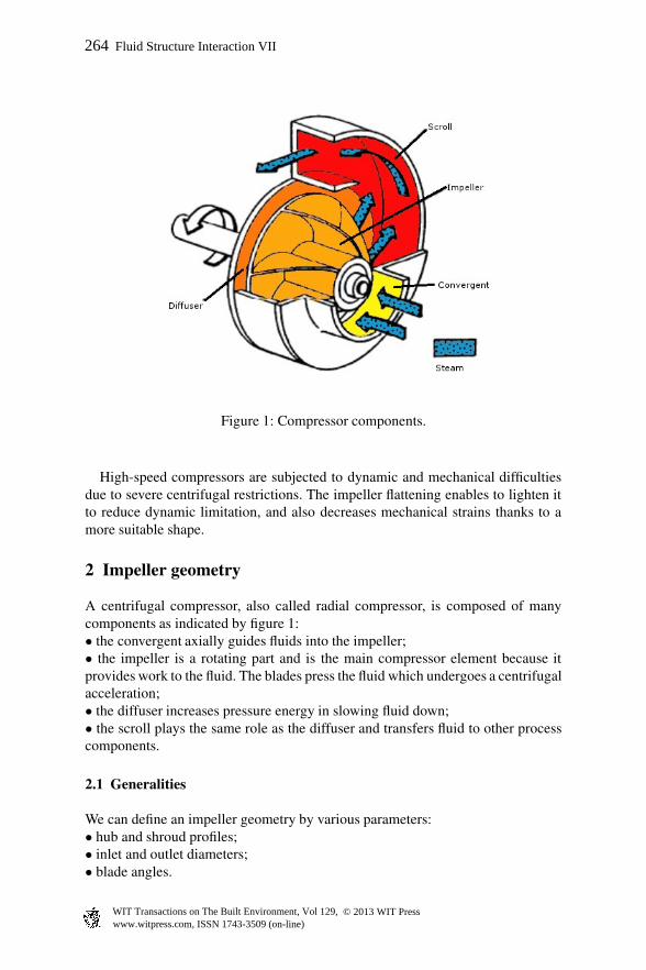
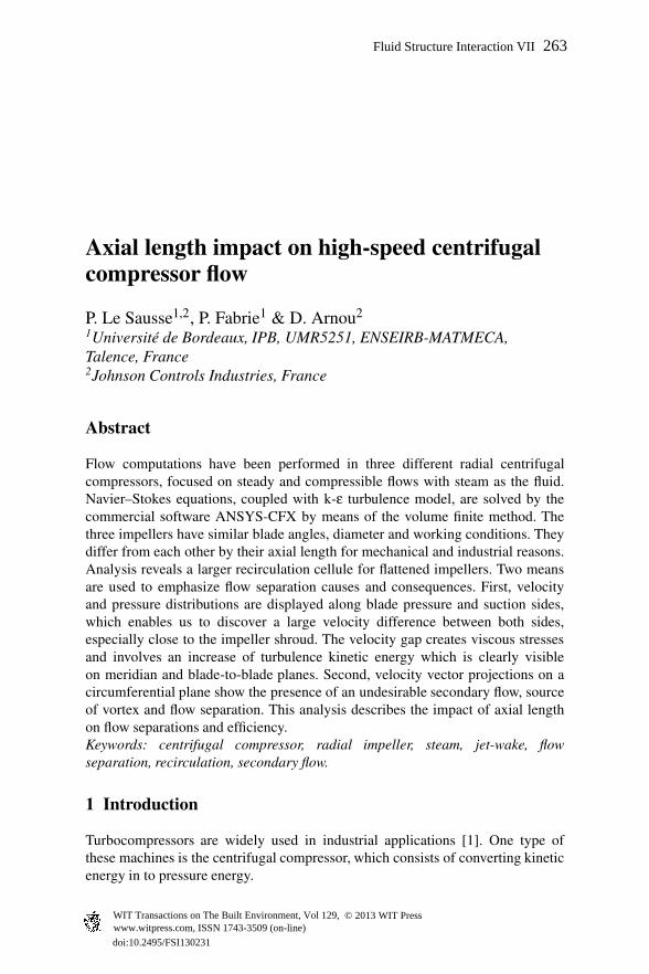
Figure 1: Compressor components.
High-speed compressors are subjected to dynamic and mechanical difficultiesdue to severe centrifugal restrictions. The impeller flattening enables to lighten itto reduce dynamic limitation, and also decreases mechanical strains thanks to amore suitable shape.
2 Impeller geometry
A centrifugal compressor, also called radial compressor, is composed of manycomponents as indicated by figure 1:• the convergent axially guides fluids into the impeller;• the impeller is a rotating part and is the main compressor element because itprovides work to the fluid. The blades press the fluid which undergoes a centrifugalacceleration;• the diffuser increases pressure energy in slowing fluid down;• the scroll plays the same role as the diffuser and transfers fluid to other processcomponents.
2.1 Generalities
We can define an impeller geometry by various parameters:• hub and shroud profiles;• inlet and outlet diameters;• blade angles.
264 Fluid Structure Interaction VII
www.witpress.com, ISSN 1743-3509 (on-line) WIT Transactions on The Built Environment, Vol 129, © 2013 WIT Press
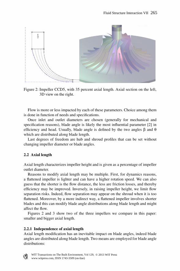
Figure 2: Impeller CCD5, with 35 percent axial length. Axial section on the left,3D view on the right.
Flow is more or less impacted by each of these parameters. Choice among themis done in function of needs and specifications.
Once inlet and outlet diameters are chosen (generally for mechanical andspecification reasons), blade angle is likely the most influential parameter [2] inefficiency and head. Usually, blade angle is defined by the two angles β and θwhich are distributed along blade length.
Last degrees of freedom are hub and shroud profiles that can be set withoutchanging impeller diameter or blade angles.
2.2 Axial length
Axial length characterizes impeller height and is given as a percentage of impelleroutlet diameter.
Reasons to modify axial length may be multiple. First, for dynamics reasons,a flattened impeller is lighter and can have a higher rotation speed. We can alsoguess that the shorter is the flow distance, the less are friction losses, and therebyefficiency may be improved. Inversely, in raising impeller height, we limit flowseparation risks. Indeed, flow separation may appear on the shroud when it is tooflattened. Moreover, by a more indirect way, a flattened impeller involves shorterblades and this can modify blade angle distributions along blade length and mightaffect the flow.
Figures 2 and 3 show two of the three impellers we compare in this paper:smaller and bigger axial length.
2.2.1 Independence of axial lengthAxial length modification has an inevitable impact on blade angles, indeed bladeangles are distributed along blade length. Two means are employed for blade angledistributions:
Fluid Structure Interaction VII 265
www.witpress.com, ISSN 1743-3509 (on-line) WIT Transactions on The Built Environment, Vol 129, © 2013 WIT Press
Figure 3: Impeller CCD5, with 20 percent axial length. Axial section on the left,3D view on the right.
• in relation to blade length M;• in relation to blade length percentage M%.When axial length is modified, blade length is necessarily changed also. Thatis why it is important to distinguish distributions in relation to the blade lengthbetween distributions in relation to the blade length percentage.
3 Numerical simulations
Three impellers are analyzed using the commercial computational fluid [3]dynamic (CFD) software ANSYS-CFX using a finite volume method [4].
Due to periodicity features of the impeller geometry, only one passagecontaining one main blade and one splitter (secondary blade) was modeled. Toensure a good transition between impeller and diffuser and to improve calculationcosts, we apply the same periodicity on diffuser geometry.
The model uses a structured mesh made of hexahedrons. The mesh containsseveral thin layers along wall for accurate boundary layers calculation.
The boundary conditions are following:• total pressure at the inlet;• total temperature at the inlet;• static pressure at the outlet;• 5% turbulence intensity at the inlet;• adiabatic wall with 8.5 µm of roughness on impeller and diffuser;• adiabatic wall with 0.5 mm of roughness on scroll.
Computations have solved steady and compressible Navier–Stokes equations,coupled with k− ε turbulence model, with steam as fluid.
No experimental investigation has been done on these impellers but the modelparameters (boundary conditions, physical model, mesh refinement) have beenvalidated on an existing impeller with maximum of 2% of difference withexperimental measures in compression performance (pressure ratio). That is why
266 Fluid Structure Interaction VII
www.witpress.com, ISSN 1743-3509 (on-line) WIT Transactions on The Built Environment, Vol 129, © 2013 WIT Press
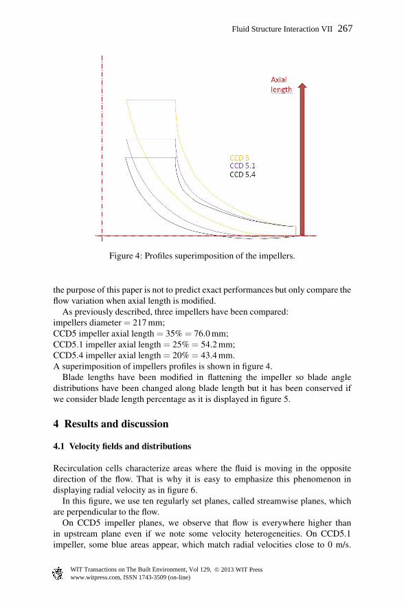
Figure 4: Profiles superimposition of the impellers.
the purpose of this paper is not to predict exact performances but only compare theflow variation when axial length is modified.
As previously described, three impellers have been compared:impellers diameter = 217 mm;CCD5 impeller axial length = 35% = 76.0 mm;CCD5.1 impeller axial length = 25% = 54.2 mm;CCD5.4 impeller axial length = 20% = 43.4 mm.A superimposition of impellers profiles is shown in figure 4.
Blade lengths have been modified in flattening the impeller so blade angledistributions have been changed along blade length but it has been conserved ifwe consider blade length percentage as it is displayed in figure 5.
4 Results and discussion
4.1 Velocity fields and distributions
Recirculation cells characterize areas where the fluid is moving in the oppositedirection of the flow. That is why it is easy to emphasize this phenomenon indisplaying radial velocity as in figure 6.
In this figure, we use ten regularly set planes, called streamwise planes, whichare perpendicular to the flow.
On CCD5 impeller planes, we observe that flow is everywhere higher thanin upstream plane even if we note some velocity heterogeneities. On CCD5.1impeller, some blue areas appear, which match radial velocities close to 0 m/s.
Fluid Structure Interaction VII 267
www.witpress.com, ISSN 1743-3509 (on-line) WIT Transactions on The Built Environment, Vol 129, © 2013 WIT Press
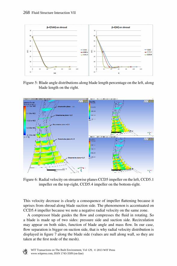
Figure 5: Blade angle distributions along blade length percentage on the left, alongblade length on the right.
Figure 6: Radial velocity on streamwise planes CCD5 impeller on the left, CCD5.1impeller on the top-right, CCD5.4 impeller on the bottom-right.
This velocity decrease is clearly a consequence of impeller flattening because ituprises from shroud along blade suction side. The phenomenon is accentuated onCCD5.4 impeller because we note a negative radial velocity on the same zone.
A compressor blade guides the flow and compresses the fluid in rotating. Soa blade is made up of two sides: pressure side and suction side. Recirculationmay appear on both sides, function of blade angle and mass flow. In our case,flow separation is bigger on suction side, that is why radial velocity distribution isdisplayed in figure 7 along the blade side (values are null along wall, so they aretaken at the first node of the mesh).
268 Fluid Structure Interaction VII
www.witpress.com, ISSN 1743-3509 (on-line) WIT Transactions on The Built Environment, Vol 129, © 2013 WIT Press
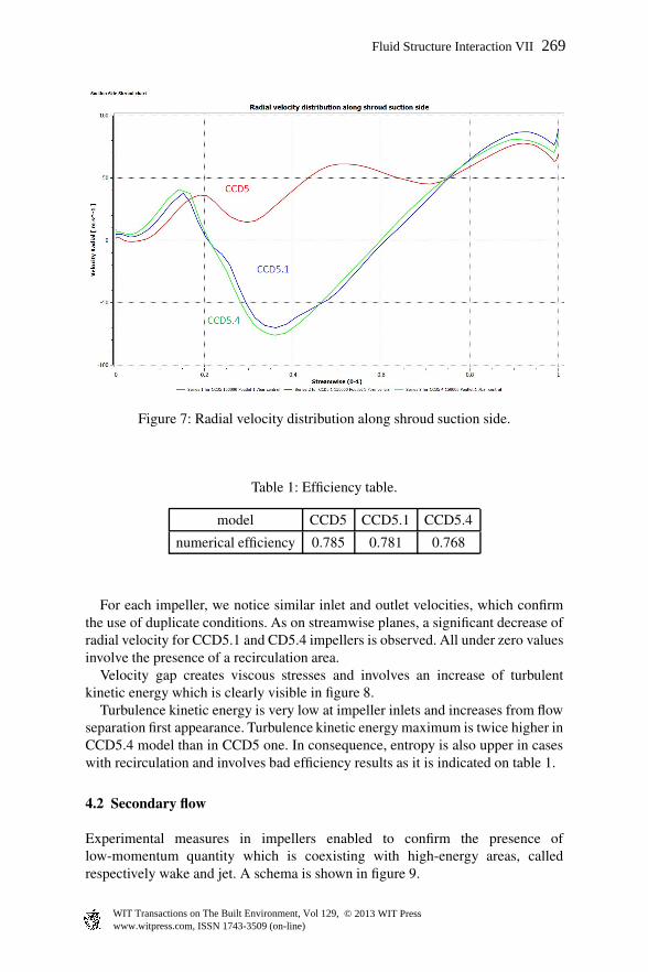
Figure 7: Radial velocity distribution along shroud suction side.
model CCD5 CCD5.1 CCD5.4
numerical efficiency 0.785 0.781 0.768
Table 1: Efficiency table.
For each impeller, we notice similar inlet and outlet velocities, which confirmthe use of duplicate conditions. As on streamwise planes, a significant decrease ofradial velocity for CCD5.1 and CD5.4 impellers is observed. All under zero valuesinvolve the presence of a recirculation area.
Velocity gap creates viscous stresses and involves an increase of turbulentkinetic energy which is clearly visible in figure 8.
Turbulence kinetic energy is very low at impeller inlets and increases from flowseparation first appearance. Turbulence kinetic energy maximum is twice higher inCCD5.4 model than in CCD5 one. In consequence, entropy is also upper in caseswith recirculation and involves bad efficiency results as it is indicated on table 1.
4.2 Secondary flow
Experimental measures in impellers enabled to confirm the presence oflow-momentum quantity which is coexisting with high-energy areas, calledrespectively wake and jet. A schema is shown in figure 9.
Fluid Structure Interaction VII 269
www.witpress.com, ISSN 1743-3509 (on-line) WIT Transactions on The Built Environment, Vol 129, © 2013 WIT Press
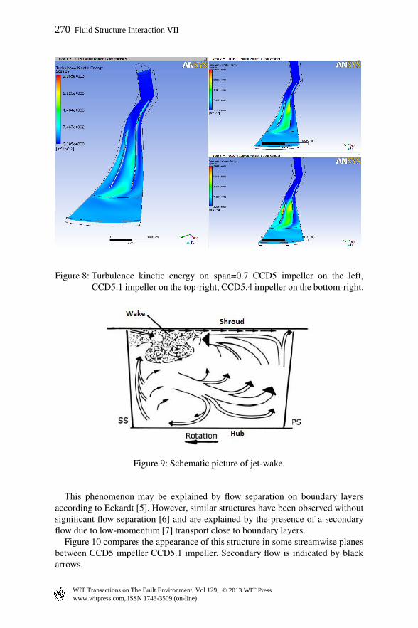
Figure 8: Turbulence kinetic energy on span=0.7 CCD5 impeller on the left,CCD5.1 impeller on the top-right, CCD5.4 impeller on the bottom-right.
Figure 9: Schematic picture of jet-wake.
This phenomenon may be explained by flow separation on boundary layersaccording to Eckardt [5]. However, similar structures have been observed withoutsignificant flow separation [6] and are explained by the presence of a secondaryflow due to low-momentum [7] transport close to boundary layers.
Figure 10 compares the appearance of this structure in some streamwise planesbetween CCD5 impeller CCD5.1 impeller. Secondary flow is indicated by blackarrows.
270 Fluid Structure Interaction VII
www.witpress.com, ISSN 1743-3509 (on-line) WIT Transactions on The Built Environment, Vol 129, © 2013 WIT Press
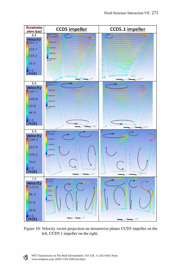
Figure 10: Velocity vector projection on streamwise planes CCD5 impeller on theleft, CCD5.1 impeller on the right.
Fluid Structure Interaction VII 271
www.witpress.com, ISSN 1743-3509 (on-line) WIT Transactions on The Built Environment, Vol 129, © 2013 WIT Press
On streamwise plane = 1.2, we note higher velocities on CCD5.1 model thanCCD5 on the top-right. Then, on streamwise plane = 1.3, a recirculation appearson the same area on CCD5.1 whereas it does not exist on CCD5. On streamwiseplane = 1.4, this recirculation increases and it matches the same area as flowseparation previously observed. These vortexes are displayed in red in the figure.
Figures 7 and 10 allow us to discover an interesting fluid acceleration before theflow separation.
5 Conclusion
Axial length impact on high-speed centrifugal compressor is distinctlyemphasized with different means and involves the necessity to be applied withparsimoniousness.
First, we analyzed the radial velocity variable either in displaying it on suitableplanes or in using distribution along blade suction side. It allows to emphasizenegative values and recirculations.
Turbulence kinetic energy and entropy show the impact on losses which resultin efficiency decrease.
The development of jet-wake structure enables a detailed view of the flowbetween blades. We can observe appearances of vortex in different impellersections.
A flattened impeller may be required by a mechanical design but can be notoptimized for aeraulic performances. Then it involves a compromise betweenmechanical and aeraulic design.
Moreover, this study does not enable us to know if the flow separation is due toshroud profile or blade angle distribution. In this last case, blade angle modificationmay improve flow quality.
References
[1] A. Javed, R.P., M. Olivero & Buijtenen, J.V., Performance analysis of amicroturbine centrifugal compressor from a manufacturing perspective. ASMETurbo Expo, 2011.
[2] Jongsik, G.A., C. Buckley, Numerical study on the effects of blade lean onhigh pressure centrifugal impeller performance. ASME Turbo Expo, 2011.
[3] Vierendeels, J. & Degroote, J., Aspect of CFD Computations with commercialpackages. pp. 305–328, 2009.
[4] Meauze, G., Turbomachines : calcul des ecoulements incompressibles.Technique de l’ingenieur, 1982.
[5] Eckardt, D., Detailed flow investigation within a high-speed centrifugalcompressor impeller. ASME Journal of fluids engineering, 1976.
[6] Ch. Hirsch, S.K. & Pointel, G., A numerically supported investigation of the3d flow in centrifugal impellers. part II: Secondary flow structure. ASMETurbo Expo, 1996.
[7] C. Gmelin, K.L., F. Thiele & Meyer, R., Investigations of secondary flowsuction in a high speed compressor cascade. ASME Turbo Expo, 2011.
272 Fluid Structure Interaction VII
www.witpress.com, ISSN 1743-3509 (on-line) WIT Transactions on The Built Environment, Vol 129, © 2013 WIT Press