Axial Fan Report
5
1.0 Introduction The distinguishing characteristic of power machine/work machine can be classified in the direction of the flowing energy. The power machine is the fluids energy removed by the machine and converted into shafts, while the work machine is the energy transferred to the fluid by giving pressure or the flow velocity to increase the fluid. Axial fan is an application of turbo machines. A turbo machine continuously added energy to or removed from the flow by deflection at stator and rotor blades. The kinetic energy is converted into pressure energy or mechanical energy. In the physical application, the law of conservation, which is the continuity equation, is used to determine the compressibility or the incompressibility of the fluid density. The conservation of momentum equation can be applying the change in momentum with the change of velocity. The conservation of energy can be applied with similar quantities of Joules, converting electrical energy to mechanical energy and to hydraulic energy. Axial fans are used to transport gases. The medium to be transported is drawn in axially to the drive shaft of the axial fan by the rotation of the rotor. The medium flows through the rotor and is discharged axially behind the rotor. The experimental unit provides the basic experiments to get to know the operating behavior and the important characteristic variables of axial fans. objectives to determine the operating behaviour and characteristic variables of an axial fan to determine the recording the fan characteristic (differential pressure as a function of the flow rate)
-
Upload
azri-lundu -
Category
Documents
-
view
228 -
download
1
description
axial fan report
Transcript of Axial Fan Report

1.0 Introduction
The distinguishing characteristic of power machine/work machine can be classified in thedirection of the flowing energy. The power machine is the fluids energy removed by themachine and converted into shafts, while the work machine is the energy transferred to thefluid by giving pressure or the flow velocity to increase the fluid.Axial fan is an application of turbo machines. A turbo machine continuously added energy toor removed from the flow by deflection at stator and rotor blades. The kinetic energy isconverted into pressure energy or mechanical energy. In the physical application, the law ofconservation, which is the continuity equation, is used to determine the compressibility or theincompressibility of the fluid density. The conservation of momentum equation can beapplying the change in momentum with the change of velocity. The conservation of energycan be applied with similar quantities of Joules, converting electrical energy to mechanicalenergy and to hydraulic energy.
Axial fans are used to transport gases. The medium to be transported is drawn in axially tothe drive shaft of the axial fan by the rotation of the rotor. The medium flows through therotor and is discharged axially behind the rotor. The experimental unit provides the basicexperiments to get to know the operating behavior and the important characteristic variablesof axial fans.
objectives to determine the operating behaviour and characteristic variables of an axial fan to determine the recording the fan characteristic (differential pressure as a function of the
flow rate) to determine the effect of the rotor speed on the pressure and the flow rate to determine the hydraulically power output and efficiencies.
2.0 Apparatus
Parts: 1) Intake pipe2) Temperature sensor3) Drive motor4) Axial fan (V-A)5) Housing6) Throttle valve (V1)7) Delivery pipe8) Measuring gauge for dpf
9) Measuring gauge for dpN
3.0 Experiment Procedure
a) Record atmospheric pressure and ambient temperature.b) Operate the fan and read fan rotational speed from fan driver control panel.c) Measure the fan characteristic dependent with the throttle valved) Wait for the measurement to stable.e) Repeat for all values of the throttle valve (9 values).f) Repeat until speed of 100%g) Save measurement fileh) Plot the fan characteristics
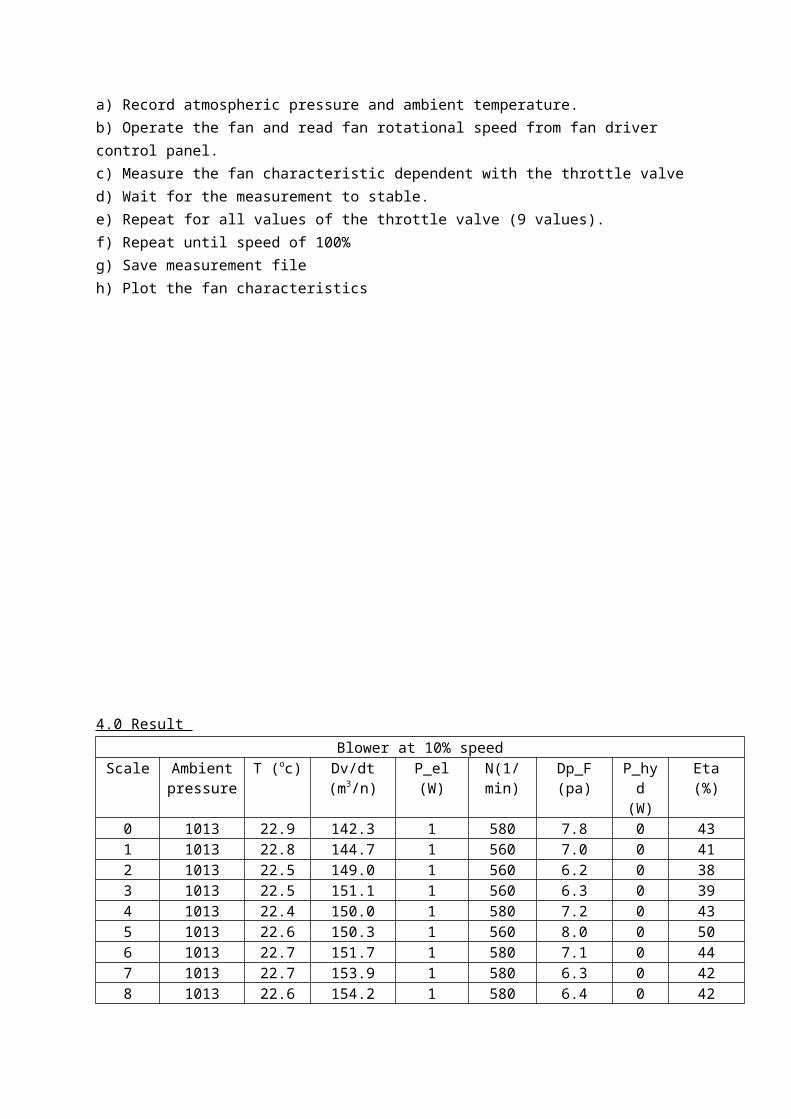
4.0 Result Blower at 10% speed
Scale Ambient pressure
T (oc) Dv/dt (m3/n)
P_el (W) N(1/min) Dp_F (pa) P_hyd (W)
Eta (%)
0 1013 22.9 142.3 1 580 7.8 0 431 1013 22.8 144.7 1 560 7.0 0 412 1013 22.5 149.0 1 560 6.2 0 383 1013 22.5 151.1 1 560 6.3 0 394 1013 22.4 150.0 1 580 7.2 0 435 1013 22.6 150.3 1 560 8.0 0 506 1013 22.7 151.7 1 580 7.1 0 447 1013 22.7 153.9 1 580 6.3 0 428 1013 22.6 154.2 1 580 6.4 0 429 1013 22.7 153.4 1 580 7.3 0 43
Blower at 60% speedScale Ambient
pressureT (oc) Dv/dt
(m3/n)P_el (W) N(1/min) Dp_F (pa) P_hyd
(W)Eta (%)
0 1013 23.4 160.1 29 5942 286.5 13 441 1013 23.1 205.7 24 6036 195.2 11 462 1013 22.3 407.8 26 5998 92.2 10 393 1013 21.8 405.7 26 5990 94.7 11 414 1013 22.5 207.1 24 6034 195.2 11 465 1013 22.6 161.9 29 5946 287.2 13 456 1013 22.7 214.0 24 6010 190.4 11 477 1013 22.0 402.0 26 5942 92.1 10 408 1013 21.8 417.1 26 5966 87.6 10 399 1013 21.9 208.8 24 6002 192.9 11 47
Blower at 80% speedScale Ambient
pressureT (oc) Dv/dt
(m3/n)P_el (W) N(1/min) Dp_F (pa) P_hyd
(W)Eta (%)
0 1013 24.2 173.3 64 8006 515.1 25 39
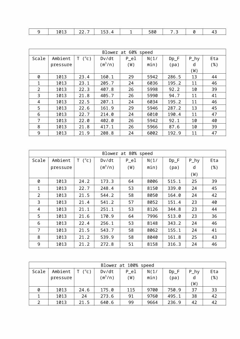
1 1013 22.7 248.4 53 8150 339.0 24 452 1013 21.5 544.2 58 8050 164.0 24 423 1013 21.4 541.2 57 8052 151.4 23 404 1013 21.1 251.1 53 8126 344.8 23 445 1013 21.6 170.9 64 7996 513.0 23 366 1013 22.4 256.1 53 8148 343.2 24 467 1013 21.5 543.7 58 8062 155.1 24 418 1013 21.2 539.9 58 8040 161.8 25 439 1013 21.2 272.8 51 8158 316.3 24 46
Blower at 100% speedScale Ambient
pressureT (oc) Dv/dt
(m3/n)P_el (W) N(1/min) Dp_F (pa) P_hyd
(W)Eta (%)
0 1013 24.6 175.0 115 9700 750.9 37 331 1013 24 273.6 91 9760 495.1 38 422 1013 21.5 640.6 99 9664 236.9 42 423 1013 21.1 643.0 99 9668 223.2 40 404 1013 21.2 288.3 87 9732 471.8 38 435 1013 22.3 175.5 114 9704 749.0 37 326 1013 23.1 277.5 89 9732 482.6 37 427 1013 21.5 620.7 97 9676 222.6 40 418 1013 21.8 650.1 98 9692 223.0 39 409 1013 21.6 271.4 92 9732 502.2 38 42
ConclusionBased on the experiment that has been conducted, we are able to measure pressure,
horsepower and efficiency of each scale at certain percent of blower and knowing that the pressure decreases when knob is opening. So, based on the data collected, we can conclude that when the blower is increasing it rotation, the value of pressure and horsepower also increasing but the efficiency is still same.
Recommendation Fix the knob scale because it is also moving when we want to change the scale value. Wait the data to get the average when change the value. Make sure not put the value of blower exceed 130%.
References
Appendix
AcknowledgementThanks to the following staff for their contributions in preparing the laboratory sheet:
i. Muhamad Ammar Bin Nik Mutasim