AX Hydraulic Diaphragm Metering
12
Metering pumps AX series PDF-A 0032-03
Transcript of AX Hydraulic Diaphragm Metering

8/13/2019 AX Hydraulic Diaphragm Metering
http://slidepdf.com/reader/full/ax-hydraulic-diaphragm-metering 1/12
Metering pumps
AX series
PDF-A 0032-03

8/13/2019 AX Hydraulic Diaphragm Metering
http://slidepdf.com/reader/full/ax-hydraulic-diaphragm-metering 2/12
AXK -PL
AXA-K AXK -DM
(with pneumatic servo unit)
Th e h igh est r iliab ility system m ete r in g
1
Iwaki metering pumps AX series are compact hydraulic diaphragm pumps
designed to meet the exacting requirements of modern advanced chemical processes.
The light, compact body incorporates a highly reliable driving unit
and unique hydraulic system to assure high,
stable performance over long-term continuous operation.
In addition, the new-type servo system with built-in positioner and numerous accessories,
are standardized to meet the most stringent service demands
of chemical liquid feeding processes,
making the AX series suitable for wide application not only in the chemical industry
but in many other fields such as paper, food, and waste-water treatment.
High precision and reliabilityIwak i A X series are highly precise and reliable
metering pumps for chemical processes which
achieve metering accuracy within ±1% (see N ote
1), linearity within ±2% (see Note 3) and feature a
driving unit specially designed for long-term
continuous operation.
Improved cost performanceThe mechanical efficiency of the reduction gear as
well as that of the entire pump is improved. In
addition, the employment of a large-capacity pump
head and the standardization of high-speed types
have further improved the cost efficiency of the
pump.

8/13/2019 AX Hydraulic Diaphragm Metering
http://slidepdf.com/reader/full/ax-hydraulic-diaphragm-metering 3/12
AXJ-DL
3AXA-DL
(3-hesds type)
AXA -DL
(with electric servo unit)
Metering pumps
p u m p
2
Compact and lightweightAn integrated SL crank and worm reduction gear
incorporated in the compact driving unit, reducing
the pump installation area to a half or less as well
as the overall weight to 2/3 or less.
New integrated servo systemwith built-in positionerA n integrated servo unit with built-in positioner is
employed, which directly controls the pump via
mA D C signal. T his new type servo system has
simplified both instrumentation work and also field
adjustment.
N ote 1: Metering a ccuracy (repeatab ility) expresses flow devia tion from average rated capa city under steady state operating conditi ons, when the capacity is repeatedly measured.
N ote 2: Linearity indica tes the devia tion of stroke/capacity ratio from the idea l straight line. Note that the linearity is not guaranteed.
N ote 3: Rep roducib ility describes the ability to reproduce a specific pump flow rate under a given set of conditions when capacity setting is varied. N ote that the reproducib ility is not guaranteed.

8/13/2019 AX Hydraulic Diaphragm Metering
http://slidepdf.com/reader/full/ax-hydraulic-diaphragm-metering 4/12
Hydraulic diaphragm Mechanically-driven diaphragmPlunger
SUS PVC SUSSUS PVC
3
SL crank(Screwed L crank patented in Japan and other countries)
The SL crank features a simple structure
but is capable of generating a high piston
driving force and features a highly reliable
stroke adjustment mechanism for
reciprocating pumps.
High-strength, simplified structureC ompared with conventional cranks, eg.
split cam and connecting rod, the SL
crank features a solid cam and
connecting rod, leading to
considerably increased strength.
No stroke length errorThe cam is coupled to the
crank via 10 or more screw
threads. O wing to the wide
area supporting the piston
load, it is free from problems
such as play and biting due to
crank wear during long-term
continuous operation.
Compact and lightweightA compact, lightweight driving
unit has resulted from the
reduced crank unit size.
High ly r eliab le ad van ce d m ec h an ism

8/13/2019 AX Hydraulic Diaphragm Metering
http://slidepdf.com/reader/full/ax-hydraulic-diaphragm-metering 5/12
Type of pumpHydraulic diaphragm Mechanically-driven diaphragm
SUS PVC SUSSUS PVC
Plunger
Pump head
Ball valve
Valve seat
Gasket
O-ring
Diaphragm
Plunger
SUS316/SC S14 PVC
HC/SUS316
SUS316
PTFE
–
–
PTFE
–
PTFE
–
PTFE
–
PTFE
–
–
– –
HC /SUS316/CE
PV C
EPDM /FK M EPDM /FK M
SU S304/SCS13
SUS304
SUS304
PTFE
PV C
PV C
SU S304/CE
–
SUS316
HC /SUS440C
SUS316/SUS316STL
PTFE
SUS316+HCr/CE
Others C ylinder head ( not wet end)1. Low pressure type: C ast iron
2. M edium pressure type: SC PH -2
Note: T his table shows standard material.
Please refer "AX series metering pump technical information" for detail.
SymbolsMaterial of wet end partsSCS13
SCS14
HC
440C
STL
HCr
PVC
PTFE
EPDM
FKMCE
Stainless steel (equivalent to SUS304)
Stainless steel (equivalent to SUS316)
Hastelloy C -276
Stainless steel 440C
Stellite alloy
Hard chrome plating
Non plasticized-polyvinyl chloride
Polytetrafluoroethylene (Teflon etc.)
Ethylene-propylene rubber
FluororubberCeramic
R
Electromagnetic metering pumps
4
Driving unit gear oil / hydraulic oilLubricating oil and hydraulic oil circuits are
interconnected, and common oil is used. A n air
breather is mounted on the suction port to keep out
rain water.
Automatic air vent valveThis valve automatically discharges the gas
contained in the hydraulic oi l to prevent gas lock
and maintain metering accuracy. The simple
structure assuring correct operation, ensures the
discharge of the gas contained in the hydraulic oil
together with a small amount of oil at each stroke.
Diaphragm(Spherical diaphragm)
The spherical diaphragm developed by Iwaki
operates under a unique principle,
utilizing the change in material
shape. No tensile stress acts
on the diaphragm, assuring
high durability under long-
term continuous operation.
Oil compensator valveThis is the valve to keep the oil volume of hydraulic
cylinder at the optimum level. The mechanically-
operated valve always opens at the bottom dead
position of diaphragm to avoid excess
replenishment of oil and diaphragm damage.
Pump head
Automatic air vent valve
Oil compensator valve
Ball valve
Valve seat
Gasket
Diaphragm
8/13/2019 AX Hydraulic Diaphragm Metering
http://slidepdf.com/reader/full/ax-hydraulic-diaphragm-metering 6/125
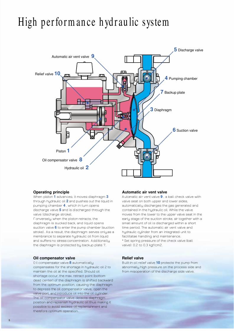
Automatic air vent valve 9
5 Discharge valve
4 Pumping chamber
7 Backup plate
3 Diaphragm
6 Suction valve
Hydraulic oil 2
Oil compensator valve 8
Piston 1
Relief valve 10
High p er fo r m an ce h yd r au lic system
Operating principleWhen piston 1 advances, it moves diaphragm 3
through hydraulic oil 2 and pushes out the liquid in
pumping chamber 4 , which in turn opens
discharge valve 5 and is discharged through the
valve (discharge stroke).
C onversely, when the piston retracts, the
diaphragm is sucked back, and liquid opens
suction valve 6 to enter the pump chamber (suction
stroke) . A s a result, the diaphragm serves only as amembrance to separate hydraulic oil from liquid
and suffers no stress concentration. Additionally,
the diaphragm is protected by backup plate 7.
Oil compensator valveO il compensator valve 8 automatically
compensates for the shortage in hydraulic oil 2 to
maintain the oil at the specified. Should oil
shortage occur, the max. retract point (bottom
dead center) of the diaphragm is shifted backward
from the optimum position, causing the diaphragm
to depress the oil compensator valve, open thevalve port, and introduce oil into the oil cylinder.
The oil compensator valve detects diaphragm
position and replenish hydraulic oil thus making it
possible to avoid excess oil replenishment and
therefore optimum operation.
Automatic air vent valveA utomatic air vent valve 9 , a ball check valve with
valve seat on both upper and lower sides,
automatically discharges the gas generated and
contained in the hydraulic oil. While the valve
moves from the lower to the upper valve seat in the
early stage of the suction stroke, air together with a
small amount of oil is discharged within a short
time period. The automatic air vent valve and
hydraulic cylinder from an integrated unit tofacilitatae handling and maintenance.
* Set spring pressure of the check valve (ball
valve): 0.2 to 0.3 kgf/cm2.
Relief valveBuilt-in oi l relief valve 10 protects the pump from
abnormally high pressure on the process side and
from misoperation of the discharge side valve.

8/13/2019 AX Hydraulic Diaphragm Metering
http://slidepdf.com/reader/full/ax-hydraulic-diaphragm-metering 7/12
Electromagnetic metering pumps
6
Series configuration
Driving unit
Hydraulic system and pump unitPneumaticservo system
Electricservo system
General purposeflange motor
Inverter motor
VS motor
AXJ
AXK
AXA
AXB
L Hydraulic diaphragm, low pressure type
M Hydraulic diaphragm, medium pressure type
K/KE Mechanically-driven diaphragm
P Plunger
PL: Max. discharge pressure 5.0MPa
PL: 5.0MPa < Max. discharge pressure 20.0MPa
PL: Max. discharge pressure > 20.0MPa
SUS
SUS
SUS PVC
SUS
Hastelloy C
Titanium
PVC
PTFE
Motor unit
Pulse generator
Servo unit
A X- L AX- K AX- P AX- M
Wid e var ie ty o f p u m p co m p o n en ts

8/13/2019 AX Hydraulic Diaphragm Metering
http://slidepdf.com/reader/full/ax-hydraulic-diaphragm-metering 8/12
Max. discharge flow L/min Maximumdischarge pressure
MPaNumber of strokes (spm) at 50Hz Number of strokes (spm) at 60Hz
Pistondiameter
ø mmG: 48 W: 72 H: 96 R: 120 G: 58 W: 86 H: 116
30
42
52
68
0.741
1.45
2.25
3.89
1.11
2.18
3.37
5.83
1.48
2.90
4.50
7.73
1.85
3.63
5.62
9.73
0.892
1.75
2.71
4.68
1.34
2.62
4.07
7.03
1.78
3.50
5.42
9.38
1.0
1.0
0.7
0.4
Note: The m aximum discharge pressure in the table applies to stainless steel type.
That for PV C type is 0.7MP a.
Max. discharge flow L/min Maximumdischarge pressure
MPaNumber of strokes (spm) at 50Hz Number of strokes (spm) at 60Hz
Pistondiameter
ø mmG: 48 W: 72 H: 96 R: 120 G: 58 W: 86 H: 116
42
52
68
85
100
1.83
2.81
4.81
7.52
10.5
2.75
4.22
7.21
11.2
15.7
3.67
5.63
9.62
15.0
21.0
4.59
7.03
12.0
18.8
26.3
2.21
3.39
5.79
9.05
12.6
3.32
5.09
8.70
13.6
19.0
4.42
6.78
11.6
18.1
25.3
1.0
1.0
0.7 - 0.8
0.4 - 0.5
0.3
Note: The m aximum discharge pressure in the table applies to stainless steel type.
That for PV C type is 0.7MP a.
Max. discharge flow L/min Maximumdischarge pressure
MPaNumber of strokes (spm) at 50Hz Number of strokes (spm) at 60Hz
Pistondiameter
ø mmG: 48 W: 72 H: 96 R: 120 G: 58 W: 86 H: 116
7
11
15
22
30
42
0.022
0.061
0.118
0.254
0.478
0.918
0.034
0.092
0.177
0.381
0.717
1.37
0.045
0.123
0.236
0.508
0.956
1.83
0.056
0.153
0.295
0.636
1.19
2.29
0.027
0.073
0.142
0.305
0.574
1.10
0.040
0.110
0.212
0.458
0.860
1.66
0.054
0.147
0.283
0.610
1.14
2.21
1.0
1.0
1.0
1.0
1.0
0.7
Note: The maximum discharge pressure in the table applies to stainless steel type.
That for PVC type is 0.7M Pa.
Max. discharge flow L/min Maximumdischarge pressure
MPaNumber of strokes (spm) at 50Hz Number of strokes (spm) at 60Hz
Pistondiameter
ø mmG: 48 W: 72 H: 96 R: 120 G: 58 W: 86 H: 116
52
6885
100
122
3.75
6.4110.0
13.7
20.6
5.62
9.6215.0
20.5
30.9
7.5
12.820.0
27.4
41.3
9.38
16.025.0
34.3
51.6
4.51
7.7212.0
16.5
24.8
6.78
11.618.1
24.8
37.3
9.04
15.424.1
33.0
49.7
1.0
1.00.7 - 1.0
0.5 - 0.7
0.3 - 0.5
Note: The m aximum discharge pressure in the table applies to stainless steel type.
That for PV C type is 0.7MP a.
AXJStroke lengthStandard motor
: 0 to 15mm: 0.2kW
Stroke lengthStandard motor
: 0 to 24mm: 0.4/0.2kW
Stroke length
Standard motor
: 0 to 30mm
: 0.75/0.4kW
Stroke lengthStandard motor
: 0 to 40mm: 1.5/0.75kW
AXK
AXA
AXB
6 0 0
425
4 5 4
335
3 5 6
261
3 1 9
216
AX-L Hydraulic diaphragm, Low pressure type
AXJStroke lengthStandard motor
: 0 to 15mm: 0.2kW
Stroke lengthStandard motor
: 0 to 24mm: 0.4kW
Stroke length
Standard motor
: 0 to 30mm
: 0.75kW
Stroke lengthStandard motor
: 0 to 40mm: 1.5kW
AXK
AXA
AXB
AX-M Hydraulic diaphragm, Medium pressure type
Max. discharge flow L/min Maximumdischarge pressure
MPaNumber of strokes (spm) at 50Hz Number of strokes (spm) at 60Hz
Pistondiameter
ø mmG: 48 W: 72 H: 96 R: 120 G: 58 W: 86 H: 116
11
15
22
30
0.054
0.108
0.246
0.468
0.082
0.162
0.369
0.702
0.109
0.216
0.492
0.936
0.136
0.270
0.615
1.17
0.065
0.129
0.295
0.561
0.098
0.194
0.443
0.842
0.131
0.259
0.591
1.12
5.0
5.0
2.5
1.3
Max. discharge flow L/min Maximumdischarge pressure
MPaNumber of strokes (spm) at 50Hz Number of strokes (spm) at 60Hz
Pistondiameter
ø mmG: 48 W: 72 H: 96 R: 120 G: 58 W: 86 H: 116
22
30
0.385
0.733
0.578
1.10
0.771
1.46
0.964
1.83
0.464
0.883
0.697
1.32
0.930
1.76
3.8
2.0
Max. discharge flow L/min Maximumdischarge pressure
MPaNumber of strokes (spm) at 50Hz Number of strokes (spm) at 60Hz
Pistondiameter
ø mmG: 48 W: 72 H: 96 R: 120 G: 58 W: 86 H: 116
30
42
52
0.916
1.79
2.75
1.37
2.69
4.13
1.83
3.59
5.50
2.29
4.49
6.88
1.10
2.16
3.31
1.65
3.24
4.98
2.20
4.33
6.64
4.2 - 3.7
2.1-1.9
1.4 -1.2
Max. discharge flow L/min Maximumdischarge pressure
MPaNumber of strokes (spm) at 50Hz Number of strokes (spm) at 60Hz
Pistondiameter
ø mmG: 48 W: 72 H: 96 R: 120 G: 58 W: 86 H: 116
42
5268
2.39
3.676.27
3.59
5.59.41
4.79
7.3412.5
5.98
9.1815.6
2.88
4.427.56
4.33
6.6411.3
5.77
8.8515.1
3.0 - 4.2
1.9 - 2.71.3 -1.6
6 0 0
425
4 5 4
335
4 0 6
261
3 7 4
216
Major standard specifications (Dimensions in mm)
7

8/13/2019 AX Hydraulic Diaphragm Metering
http://slidepdf.com/reader/full/ax-hydraulic-diaphragm-metering 9/12
Stroke lengthStandard motor
: 0 to 40mm: 1.5/0.75kWAXB
AXJStroke lengthStandard motor
: 0 to 15mm: 0.2kW
Stroke lengthStandard motor
: 0 to 24mm: 0.4/0.2kW
Stroke length
Standard motor
: 0 to 30mm
: 0.75/0.4kW
AXK
AXA
AX-P Plunger
AXJMotor output : 0.4kW
Motor output : 1.5/0.75kW
AXK
AX-K/KE Mechanically-driven diaphragm
Max. discharge flow L/min Maximumdischarge pressure
MPaNumber of strokes (spm) at 50Hz Number of strokes (spm) at 60Hz
Plungerdiameter
ø mmG: 48 W: 72 H: 96 R: 120 G: 58 W: 86 H: 116
05
08
11
16
22
32
0.012
0.032
0.062
0.137
0.260
0.550
0.019
0.048
0.093
0.206
0.390
0.825
0.025
0.065
0.124
0.275
0.520
1.10
0.031
0.081
0.155
0.343
0.650
1.37
0.015
0.039
0.074
0.165
0.312
0.660
0.023
0.058
0.112
0.247
0.468
0.990
0.030
0.078
0.149
0.330
0.624
1.32
10.0
19.4
10.3
4.8
2.5
1.2
44 1.01 1.52 2.03 2.54 1.22 1.84 2.45 0.6
Max. discharge flow L/min Maximumdischarge pressure
MPaNumber of strokes (spm) at 50Hz Number of strokes (spm) at 60Hz
Plunger
diameterø mm
G: 48 W: 72 H: 96 R: 120 G: 58 W: 86 H: 116
08
11
16
22
32
44
0.051
0.097
0.215
0.407
0.861
1.62
0.076
0.146
0.323
0.611
1.29
2.44
0.102
0.195
0.431
0.814
1.72
3.25
0.127
0.243
0.538
1.01
2.15
4.07
0.061
0.117
0.259
0.490
1.03
1.96
0.092
0.176
0.389
0.736
1.55
2.94
0.123
0.235
0.519
0.982
2.07
3.92
29.2
15.4
7.3
3.8
1.8
0.9
Max. discharge flow L/min Maximumdischarge pressure
MPaNumber of strokes (spm) at 50Hz Number of strokes (spm) at 60Hz
Plunger
diameterø mm
G: 48 W: 72 H: 96 R: 120 G: 58 W: 86 H: 116
08
11
16
22
32
44
0.063
0.120
0.260
0.498
1.07
2.03
0.095
0.180
0.391
0.747
1.61
3.05
0.127
0.241
0.521
0.997
2.15
4.07
0.159
0.301
0.652
1.24
2.69
5.09
0.076
0.145
0.314
0.600
1.29
2.45
0.115
0.218
0.471
0.901
1.94
3.68
0.153
0.290
0.628
1.20
2.59
4.90
34.3
26.8
12.6
6.7
3.1
1.6
58 3.53 5.30 7.07 8.84 4.26 6.40 8.53 0.9
68 4.86 7.29 9.72 12.1 5.85 8.79 11.7 0.6
Max. discharge flow L/min Maximumdischarge pressure
MPaNumber of strokes (spm) at 50Hz Number of strokes (spm) at 60Hz
Plunger
diameterø mm
G: 48 W: 72 H: 96 R: 120 G: 58 W: 86 H: 116
11
16
22
32
44
58
0.16
0.347
0.664
1.43
2.71
4.71
0.241
0.521
0.996
2.15
4.07
7.07
0.321
0.695
1.32
2.87
5.43
9.43
0.401
0.869
1.66
3.58
6.78
11.7
0.193
0.418
0.8
1.72
3.27
5.67
0.29
0.628
1.2
2.59
4.91
8.52
0.387
0.838
1.6
3.46
6.54
11.3
35.0
19.5
10.5
4.8
2.5
1.4
68 6.48 9.72 12.9 16.2 7.8 11.7 15.6 1.1
88 10.8 16.2 21.7 27.1 13.0 19.6 26.1 0.6
6 0 0
425
4 5 4
335
4 0 6
261
3 7 4
216
Max. discharge flow L/min Maximumdischarge pressure
MPaNumber of strokes (spm) at 50Hz Number of strokes (spm) at 60HzModel
G: 48 W: 72 H: 96 G: 58 W: 86 H: 116
K90
K120
KE90
KE120
1.4
3.5
1.1
2.9
2.1
5.3
1.7
4.4
2.8
7.1
–
–
1.7
4.3
1.4
3.5
2.6
6.4
2.1
5.3
3.4
8.6
–
–
0.5
0.3
0.2
0.3
Note: K is for standard. K E is for latex application.
If flow rate (which you need) exceed s value on above table, C X series is available.
Please refer CX series catalog.
Max. discharge flow L/min Maximumdischarge pressure
MPaNumber of strokes (spm) at 50Hz Number of strokes (spm) at 60HzModel
G: 48 W: 72 G: 58 W: 86
K150
K180
KE180
7.5
12.4
11.0
11.3
18.6
16.5
9.1
15.0
13.2
13.7
22.5
19.9
0.4
0.3
0.3
Note: K is for standard. K E is for latex application.
425
5 7 6
4 3 7
286
8

8/13/2019 AX Hydraulic Diaphragm Metering
http://slidepdf.com/reader/full/ax-hydraulic-diaphragm-metering 10/12
Input signal
Air supply
Operating time
Accuracy
Pneumatic-pneumatic positioner
Electric-pneumatic positioner
Pneumatic-pneumatic positioner
Electric-pneumatic positioner
Pressure
Air consumption
0.02-0.1MP a
DC 4-20mA ( Input resistance 230Ω) N ote: 1
Standard: 0.3MP a, M ax: 0.6M Pa
Normal: 30NL/min or less, M ax: 100NL/min or less
20 seconds (stroke length 0-100% )
+-3% F.S Note: 2
+-2.5% F.S
Note: 1. E xplosion proof construction of electric-pneumatic p ositioner type is class d2G 4.
2. F.S means full scale.
AX servo unit (with built-in positioner)
IWAKI stroke setter type (Stroke length indication controller)
Input signal
Output signalDevices
Power supply
Structure
Input signal
Output signal
Control functions
Indication
Power supply
Structure and dimensions
4-20mA D C (corresponding to 0 to 100% stroke length)
4-20mA DC or 1 to 5V D C
4-20mA D C
4-
20mA D C ( for stroke length indication and operation)Fully electronic positioner, servo motor, potentiometer, lim it switch
100V +-10% AC , single-phase, 50/60Hz; other voltage types available
100-115V or 200 to 240V + -10% AC , single-phase, 50/60Hz
Totally enclosed outdoor type
Ratio relay, signal limiter, zero shift, reverse operation, manual signal oscilator
(C hange over type) d igital indica tor for stroke length, input signal, and output signal
Pa nel flush mounting type, 92 square X 165
Pulse generator (Speed signal generator)
Pulse generator
P/I converter
Output
Power supply
Output
Indication
Power supply
1 pulse per revolution or 1 pulse per stroke
O pen collector output (ma ximum load current; 100mA )
10-30 VDC , current consumption of the generator main body: 20mA
4-20mA DC , with power output for pulse generator
Digi tal speed indicator
100V +-10% AC , single-phase, 50/60Hz; other voltage types available
• Pulse frequency: M aximum 240Hz ( at motor maxim um speed of 1,800 rpm)
Electric servo unitThe servo unit for the AX series features a built-in positioner,
which directly controls the pump stroke length by mADC
signal from the controller. In addition, a special stroke
controller the "Iwaki Stroke Setter" with ratio relay, signal
limiter, and other control functions has been designed to
meet automatic control requirements in a variety of fields.
This system with the simple structure facilitates both
instrumentation work as well as adjustment.
Direct control by mADC signalThis servo unit directly controls pump discharge within a range from 0 to
100% by 4 to 20mA signal from the automatic controller ( refer to Fig. 2).
Simplified electrical and instrumentation workThis servo unit requires no wiring for the servo motor and feedback
resistor which, on conventional servo systems, is indispensable. O nly
mA D C signal wiring is required, which not only improves ease of
instrumentation work but also allows control which is highly resistant
to the externally induced noise (refer to Fig. 3).
Simplified system adjustmentThe pump side servo unit is adjustment prior to delivery.U nlike
conventional systems, field adjustment between servo unit and
positioner is unnecessary.
Simplified structureThe system can be constructed with a mi nimum number of control
devices (refer to Fig. 4) .
Speed controllerWith the pump speed controller, the discharge flow of
metering pumps AX series can be linearly controlled. Flow
rate control by speed controller has the advantages of fast
response and wide control range and has become more
common with the widespread use of inverters.
The pulse generator detects the gear speed through a high
frequency pulse generating proximity switch and outputs a
digital pulse. The gear is directly coupled with the motor via
the worm shaft, not noly making it possible to obtain a correct
speed signal but also allowing adaption to any variablespeed motor.
Pneumatic servo unitThe pneumatic servo unit for AX series
employs a high torque pneumatic motor
(piston type), and gives high reliability.
Both pneumatic-pneumatic
positioner, and also electric-
pneumatic positioner which isoperated by mA DC input signal
are available.
A X serieswith electric servo unit
Stroke setter
A X serieswith pulse generator
AX serieswith pneumatic servo unit
P/I converter
Remote controller
Featu r e for pr o cess au tom atio n an d FA
9

8/13/2019 AX Hydraulic Diaphragm Metering
http://slidepdf.com/reader/full/ax-hydraulic-diaphragm-metering 11/12
Automatic control system
Fig. 1 Fig. 2 Fig. 3 Fig. 4
Fig. 5 Fig. 6 Fig. 7 Fig. 8
Pump discharge can be
directly controlled by output
signal from the controller or
ratio relay.
When the stroke setter is
installed, ratio relay, signal
limiter, zero shift, and other
control functions as well as
manual operation become
available.
An example of two-value
separate control where speed
is first controlled and then
stroke length. Speed signal is
output from the built-in pulse
generator.
C ontrolling the accumulated
number of pump strokesenables batch metering and
charging.
This type of control not only
ensures accurate speedinformation but also features
high response and a wide
control range.
Structural drawingof electric servo unit
Example of direct control Combination withstroke setter
Example of two-value control(stroke length and speed)
Speed feedbackin inverter control
Example application tobatch metering and charging
Pneumatic servo "A" type(Pneumatic-pneumatic positioner)
Pneumatic servo "D" type(Electro-pneumatic positioner)
Stroke control dial
C ontroller(P ositioner)
Servomotor
Potentiometer
Limit switch
M otor powersupply
D C
4 - 2 0 m A
* D C
1 0 0 m A
D C
4 - 2 0 m A
Stroke signal Input signal
M onitor signal
Input signal DC 4-20mA
DC 1-5V
Stroke setter AC100V
AC 100VServounit
D C
4 - 2 0 m A
D C
4 - 2 0 m A
Stroke signal Input signal
AC 100V
M otor powersupply
Servounit
Indicator
C ontroller
D C
4 - 2 0 m A
C ontroller
0.02-0.1M Pa (0.2-1kgf/cm2)
C ontrollerR emote controllerAUT O/M AN UAL
MA NUA L only
Pulse counter
M otorstop signal
Power supply
Pulse generator
M otor
DC 4-20mA
rpm
Speed feedback
Input signal
Inverter
P/I converter
Pulse generator
M otor
6 - 6 0
H z
Indication of low flow rate andaccumulated
Invertermotor
D C
4 - 2 0 m A
D C
4 - 2 0 m A
6 -
6 0 H z
DC 4-20mA
Inverter
Lowerlimiter
Inputsignal
Input signal
Strokesetter
AC100V
AC 100VServounit
Speedsignal
P/Iconverter
Strokesignal
Pulse generator
10

8/13/2019 AX Hydraulic Diaphragm Metering
http://slidepdf.com/reader/full/ax-hydraulic-diaphragm-metering 12/12
Electromagnetic metering pumps
Relief valve, back pressure valve, air chamber,and other standard equipment necessary for the metering pump piping are optionally available.
Optional accessories of various standard materials (SUS316, PVC, PVDF fluororesin) are available.
Flow checker (Flow detector)
• C apacity: 0.01–6L/min
• Working pressure: M ax. 0.5M Pa
• M aterial: PV C
Diaphragm rupture detectorD iaphragm breakage monitor for double diaphragm type
pumps. In the case of damage to the diaphragm, the
monitor detects the difference of conductivity between
hydraulic oil and process liquid and outputs an
alarm signal. Its application
range includes not only
acids and alkalis but also
organic solvents with low
conductivity.
Relief valve• C apacity: 1–70L/min
• Working pressure: 0.15–1M Pa Note: Hi gh pressure types are also available.
• M aterial: SUS316, PVC , PV DF
Back pressure valve• C apacity: 1–70L/min
• Working pressure: 0.05–0.8M Pa
• M aterial: SUS316, PVC , PVD F
Air chamber• C apacity: 1–30 liters
• Working pressure : M ax. 0.9M Pa ( SU S)
: M ax. 0.5M Pa (PVC )
• M aterial: SU S316, PV C N ote: Accumulators (B ladder type) are also available.
PVC , 1 type PVC , 3-25 type
PVC , N type SUS, 2-25 type
PVC , A type PVC , N type SU S, A type
Optional accessories