
AVTMBITE3 - BITE 3 Manual Rev B March 2005 · . BITE 3 ... Electrical Theory and Practice ......
44
AVTMBITE3 Rev B March 2005 Instruction Manual BITE 3 Battery Impedance Test Equipment HIGH VOLTAGE EQUIPMENT Read this entire manual before operating. M Valley Forge Corporate Center 2621 Van Buren Avenue Norristown, PA 19403-2329 U.S.A. 610-676-8500 www.megger.com
Transcript of AVTMBITE3 - BITE 3 Manual Rev B March 2005 · . BITE 3 ... Electrical Theory and Practice ......

AVTMBITE3 Rev B
March 2005
Instruction Manual
BITE 3 Battery Impedance Test Equipment
HIGH VOLTAGE EQUIPMENT Read this entire manual before operating.
M Valley Forge Corporate Center 2621 Van Buren Avenue Norristown, PA 19403-2329 U.S.A. 610-676-8500
www.megger.com


BITE 3 Battery Impedance Test Equipment

Copyright© 2004 by Megger. All rights reserved.
The information presented in this manual is believed to be adequate for the intended use of the product. If the product or its individual instruments are used for purposes other than those specified herein, confirmation of their validity and suitability must be obtained from Megger. Refer to the warranty information below. Specifications are subject to change without notice.
WARRANTY
Products supplied by Megger are warranted against defects in material and workmanship for a period of one year following shipment. Our liability is specifically limited to replacing or repairing, at our option, defective equipment. Equipment returned to the factory for repair must be shipped prepaid and insured. Contact your MEGGER representative for instructions and a return authorization (RA) number. Please indicate all pertinent information, including problem symptoms. Also specify the serial number and the catalog number of the unit. This warranty does not include batteries, lamps or other expendable items, where the original manufacturer’s warranty shall apply. We make no other warranty. The warranty is void in the event of abuse (failure to follow recommended operating procedures) or failure by the customer to perform specific maintenance as indicated in this manual.
M Valley Forge Corporate Center 2621 Van Buren Ave Norristown, PA 19403-2329 610-676-8500 (Telephone) 610-676-8610 (Fax) www.megger.com

AVTMBITE3 Rev B March 2005
i
Table of Contents
1 INTRODUCTION........................................................................................................................................................... 1 About the BITE 3…......................................................................................................................................................... 1 Electrical Theory and Practice ....................................................................................................................................... 2 How the BITE 3 Works .................................................................................................................................................. 2 Applications for the BITE 3........................................................................................................................................... 3 Upon Receipt of the BITE 3 .......................................................................................................................................... 3 Safety First............................................................................................................................................................................ 4 How to Use This Manual ................................................................................................................................................ 4
Typographic Conventions.......................................................................................................................................... 4 2 SAFETY................................................................................................................................................................................ 5
Overview............................................................................................................................................................................... 5 Safety Requirements .......................................................................................................................................................... 5 Cautions and Warnings .................................................................................................................................................... 6
3 CONTROLS, CONNECTORS, INDICATORS & MENUS ........................................................................... 7
Overview............................................................................................................................................................................... 7 Switches and Connectors................................................................................................................................................. 8 The Battery Module.........................................................................................................................................................12
Battery Charging..........................................................................................................................................................12 4 TEST PROCEDURES ..................................................................................................................................................15
Overview.............................................................................................................................................................................15 Step One: Perform Pre-Test Activities. ...............................................................................................................15 Step Two: Turning on the BITE 3 and Connecting the Lead Set. ..............................................................16 Step Three: Select a Site/String and Take Measurements..............................................................................17 Step Four: Perform Post-Test Activities. ............................................................................................................17
Reviewing a Test...............................................................................................................................................................18 Retesting a Cell/Jar or a Strap......................................................................................................................................18 Analyzing a Test (See Chapter 5) ................................................................................................................................18
Testing Noisy Battery Systems................................................................................................................................18 Tests Using Optional Lead Sets ..................................................................................................................................18 Reviewing and retesting .................................................................................................................................................19
5 INTERPRETING TEST RESULTS........................................................................................................................21
Overview.............................................................................................................................................................................21 Viewing (Printing) Test Results on the LCD..........................................................................................................21 Instantaneous Mode of Analysis .................................................................................................................................22 Short-term Mode of Analysis .......................................................................................................................................23 Long-term Trending........................................................................................................................................................23

AVTMBITE3 Rev B March 2005
ii
6 COMMUNICATING WITH PROACTIV ............................................................................................................25 Overview .............................................................................................................................................................................25
Information & Settings ..............................................................................................................................................26 String Information Export .......................................................................................................................................27 Firmware Updates .......................................................................................................................................................28 Data and Information Export/Upload to a PC/Laptop................................................................................29
7 MAINTENANCE AND TROUBLE SHOOTING...........................................................................................31
Overview .............................................................................................................................................................................31 Status LEDs .......................................................................................................................................................................31
Lead Set ..........................................................................................................................................................................31 Battery .............................................................................................................................................................................31
Probe Tips ..........................................................................................................................................................................32 Printer (Optional) .............................................................................................................................................................32
Configuration................................................................................................................................................................32 If the BITE 3 Needs Repairs ........................................................................................................................................33
APPENDIX A TECHNICAL SPECIFICATIONS.................................................................................................35
Electrical..............................................................................................................................................................................35 Environmental...................................................................................................................................................................36 Safety ....................................................................................................................................................................................36 Mechanical ..........................................................................................................................................................................36
APPENDIX B - Replaceable Parts...............................................................................................................................37
List of Figures Figure-1: BITE 3 transceiver ..............................................................................................................................................7
Figure-2: BITE 3 lead connections...................................................................................................................................8
Figure-3: BITE 3 battery charger connections .............................................................................................................8
Figure-4: BITE 3 battery charger condition ................................................................................................................12
Figure 5: Printer Configuration Printout......................................................................................................................32
AVTMBITE3 Rev B March 2005
1
1 INTRODUCTION
About the BITE 3…
NOTE: Before attempting to use the BITE 3, be sure that you read and understand the safety requirements and operating procedures contained in this manual.
Thank you for selecting a Megger product. This instrument has been thoroughly tested and inspected to meet rigid specifications before being shipped.
It is ready for use (after charging the battery for 24 hours) when set up and operated as described in this manual.
The BITE 3 is a testing device used to evaluate the condition of stationary battery systems. It measures:
§ AC impedance, an internal ohmic value,
§ DC terminal voltage,
§ Intercell connection resistance,
§ Float current,
§ Ripple current, and
§ Harmonic content
These measurements, along with other maintenance data such as ambient and cell temperatures, help determine the condition of a battery system.
The BITE 3 is the first instrument of its kind that can be configured through PC-based software, called ProActiv. This provides the ultimate in versatility and ease-of-use. The data from the BITE 3 is uploaded with the click of the mouse and the site/string is updated with the latest data. Furthermore, the software of the BITE 3 can be updated via the Internet to ensure that the most recent updates and enhancements are downloaded to the BITE 3.

M
AVTMBITE3 Rev B March 2005
2
The BITE 3 generates data that describes an overall condition of a battery. Weak batteries are due to a number of reasons, some of which are sulphated plates, dry-out (loss-of-compression), loose intercell connectors, grid growth, etc. The BITE 3 also measures float current which increases over time as batteries degrade. In the case of VRLAs, increasing float current can indicate impending thermal runaway. [Flooded batteries can’t runaway thermally due to the large volume of acid which merely boils off limiting battery temperature to about 260°F (125°C).]
Also measured is ripple current which is an indicator of charger output condition. Battery chargers convert ac into dc but no charger is 100% efficient. Some ac carries over into the dc network and is called “ac ripple”. If that ripple current is above about 5% (5A rms per 100Ah) then battery heating can occur thus shortening batteries’ lives. Normal aging of chargers causes a slow and tolerable increase in ac ripple. But if a diode blows, ripple current can increase three to four times which can heat the battery. Measuring ripple current helps to identify the general condition of the charger output.
Electrical Theory and Practice
A battery string is a series circuit of cells that look like resistors to the applied current. Current flows due to a voltage applied from the charger. In a series circuit, Kirchhoff’s law states that the current is the same everywhere in that circuit. Ohm’s law states that each resistor will have a voltage drop in response to the applied current regardless of whether that current is ac, dc or both. Impedance works by applying an ac current signal to the battery and measuring the resulting voltage drop. Impedance is then calculated using Ohm’s Law, Z = E/I. To get accurate internal ohmic values (impedance, etc.) the current must also be measured. A battery is connected in parallel with a load and the charger and frequently it is connected to other parallel strings. The actual current can vary based on relative condition and parallel paths for the current. Hence, it is necessary to measure current that is causing the voltage drop in order to obtain accurate impedance values.
How the BITE 3 Works
The BITE 3 works by applying an ac current signal across an individual cell/jar and measuring the ac voltage drop caused by that ac current as well as the current in the individual cell/jar. It will then calculate the impedance. The standard lead set used is dual-point, Kelvin-style. One point is for applying the current and the other for measuring the potential.
In addition to the standard impedance cell voltage and intercell connection resistance, the BITE 3 uses a patent pending technique to measure float and rippled currents. The best method to measure current is by measuring the voltage across a shunt. Megger uses the idea that there are many shunts within a battery.

Introduction
AVTMBITE3 Rev B March 2005
3
By first obtaining a strap resistance value, then using that as a shunt, the float and ripple currents can be determined. The accuracy of the float and ripple currents measurements is determined by the shunt value. See the Technical Specification Section for accuracy.
The BITE 3 does more than take measurements; it also has an on-board, user-configurable database replete with percent allowable changes. The BITE 3 works in tandem with ProActiv to configure the instrument and site/strings based on user choices. The BITE 3 and ProActiv work together to have the latest data from ProActiv downloaded into the instrument for superior on-board data analysis. All BITE 3s can then have all of the necessary information and data regardless of which BITE 3 took the last set of battery data.
Applications for the BITE 3
Some of the many types of installations that can be tested and analyzed with the BITE 3 are:
§ Telecommunications – Wireline and Wireless
§ Substations and Generating Stations
§ UPS systems
§ Service Companies
§ Railroad – Substations and S&C including CTC
§ Heavy Industrial battery back-up systems
§ Battery Manufacturing Plants
§ Emergency Lighting Units
§ Marine and Military applications
§ Many Others
Please call Megger or visit our website www.megger.com for more information.
Upon Receipt of the BITE 3
Check the equipment received against the packing list to ensure that all materials are present. Notify Megger of any shortage (tel 1-610-676-8500.)
The BITE 3 is easily operated by one technician. It is housed in a rugged plastic case and includes the following components and accessories:

M
AVTMBITE3 Rev B March 2005
4
§ The BITE 3 instrument with neck strap
§ Dual-point Lead Set with LED and spare tips
§ AC line cord and charger
§ Download cable, RS-232 null modem
§ Canvas carrying case
§ ProActiv software CD
§ Instruction manual
Please examine the instrument for damage received in transit. If you find damage, file a claim with the carrier at once. Also notify Megger or our nearest authorized sales representative, and describe the damage in detail.
Safety First
Be sure to read the safety information in Chapter 2 thoroughly and observe all safety precautions and recommendations.
How to Use This Manual
Typographic Conventions
G CAUTION Cautions alert you to possible damage to equipment.
F WARNING Warnings alert you to conditions that are potentially hazardous to people.
NOTE: Notes provide important information.

AVTMBITE3 Rev B March 2005
5
2 SAFETY
Overview
The BITE 3 and its recommended operating procedures have been designed with careful attention to safety. However, it is not possible to eliminate all hazards from electrical test equipment or to foresee every possible hazard that may occur. The user not only must follow the safety precautions contained in this manual, but also must carefully consider all safety aspects of the operation before proceeding.
Any use of electricity inherently involves some degree of safety hazard. While Megger has made every effort to reduce the hazard, the operator must assume responsibility for his or her own safety. Any work on batteries is hazardous and requires constant attention to safety. You should guard particularly against the possibility of electrolyte spills, explosion, and electrical shock.
Safety Requirements
This instrument has been designed to the IEC 61010-1 safety standard. Observe all industry standard safety rules for testing batteries.
§ The BITE 3 is designed for connection to energized systems.
§ Always disconnect optional lead sets from the battery under test.
§ The purpose of this instrument is limited to use as described in this manual. Do not use the equipment or its accessories in an explosive atmosphere. Explosive gases such as hydrogen can be present around batteries. Regardless of room ventilation, verify the conditions before testing.
§ Wear protective clothing and eye protection.
§ Ensure that test leads and probes are in good condition
§ Observe all cautions and warnings in this manual and on the equipment.
§ This instrument is to be used only by suitably trained personnel who are familiar with the hazards involved in testing high voltage dc systems.
§ Safety is the responsibility of the operator.

M
AVTMBITE3 Rev B March 2005
6
Cautions and Warnings
This manual provides cautions and warnings where applicable, and these should be strictly observed.

AVTMBITE3 Rev B March 2005
7
3 CONTROLS, CONNECTORS, INDICATORS & MENUS
Overview
The front panel of the BITE 3 comprises (clockwise from the top) the
1. Test button (used for optional lead sets)
2. Alpha-numeric keypad (symbols, too)
3. On-off switch, S1 (but it is not labeled S1.)
4. Enter button
5. LCD, ¼ VGA, monochrome
6. Audible alarm
7. Comms/Printer port, J3 (but it is not labeled J3)
8. Cursor Control
9. Menu button
10. Contrast buttons
1
3
4 6 7
8
9
2
10
5
Figure-1: BITE 3 transceiver

M
AVTMBITE3 Rev B March 2005
8
The side panels comprise the lead set connection, J1 and the CT connection, J2. (again, the ports are not labeled Jx)
J2
J1
Figure-2: BITE 3 lead connections
The battery charger connection, battery state indicator and slow charge control are here:
J4 J6
J5
Figure-3: BITE 3 battery charger connections
Switches and Connectors
S1 switch The on-off switch energizes/de-energizes the instrument. It takes about 30 seconds to boot-up and about ten seconds to shut down.
J1 Lead set The lead sets are connected here. The connector is keyed.
J2 CT The optional external CT, when used, connects into J2. It is also keyed.

Controls, Connectors, Indicators & Menus
AVTMBITE3 Rev B March 2005
9
J3 (Com & Printer) The communications and printer cable connects to J3 to communicate to a PC or laptop and to the optional printer
J4 Battery charger The output of the charger connects to the battery here. The instrument is designed to prevent usage while it is being charged as a safety item.
J5 Battery State The state of the battery is evident by the number of LED bars when this button is pushed – about 10% per LED bar. See the section “Battery State Indicator” below.
J6 Slow Charge By pressing the slow charge button while connecting the charger, the battery will slow charge and take about 48 hours. See the section “Battery State Indicator” below.
There is also an audible alarm in the instrument body and LEDs on the Dual-point Lead set to indicate circuit and measurement status. The following chart details the conditions under which the audible alarm and LEDs activate. The circuit and measurement status is also displayed on the LCD.
Red No Circuit
Yellow- Blinking Circuit found, not measuring
Yellow- Solid Circuit found, measuring
Green Measuring complete, Okay to remove probes.
LED Status Indicators
No connection
(( )) Connection detected
Measuring
Measurement complete

M
AVTMBITE3 Rev B March 2005
10
The keypad is used for entering site and string configurations. It is also used to add comments about the battery or testing that the user may wish to document. The keys’ character set is:
1( )
2ABC
3DEF
4GHI
5JKL
6MNO
7PQRS
8TUV
9WXYZ
0 (space), _
. ,.# Ωmµ%-( ) /:@!?$=<>’*
The optional CT has two modes of operation: Escape current and impedance (ripple current). It is necessary to measure “escape current” in short strings in parallel configurations, mainly found in outside plant telco installations including wireline and wireless applications. An example of this would be six battery strings of (4) 12Vdc jars in each string.
In this example, the current from the measurement has parallel paths. The instrument will measure its output current and the CT will measure the current that is flowing through the parallel paths. The output current and the escape current, together, provide accurate impedance values. Other methods that do not measure current or the BITE 3 without the optional CT may have inherent errors. By measuring the “escape” current, that is, the current that is not passing through the battery being tested, it can be subtracted from the output current to correctly calculate impedance following Ohm’s Law, Z=E/i.

Controls, Connectors, Indicators & Menus
AVTMBITE3 Rev B March 2005
11
The flowchart of the menu structure:
Under Configure/Site-Strings/ Delete, it is not possible to delete a Site and/or String until the data have been deleted first. This is to make sure that a Site/String is not accidentally deleted. To delete data, go to System/Delete Tests menu item. You will be asked “Are you sure?”
Measure
New Test Select a String (Test screen – starts with temp (manual entry), ripple current and float current measurements then goes into impedance, voltage and strap testing
Discard measurement Comments Save and Close Cancel and Close
Append to Test Select a String (Test screen – starts with impedance, voltage and strap testing. There is no mechanism for float and ripple current measurements.)
Measure current Measure impedance Cancel and Close
Quick Test
Spectrum Analyzer
Analyze
Analyze Select a Test
Select and Continue Close
Configure
Instrument Instrument Name: Auto Off: (time in seconds) Line Frequency: (Hz) Auto Measure: (0/1) CT Mode: (Escape Current/ Impedance) System Time: (y/m/d h:m) Save and Close Cancel and Close
Sites/Strings Select a Site or String
New Enter New Site information Site: String Name: Baseline: (mOhms) Warning: (%) Fail: (%) Change: (%) Deviation: (%)
Save and New Save and Close Cancel and Close
Modify Modify String Information (same info as New)
Save and Close Cancel and Close
Delete Select a Site or String Are you sure?
Close Display Temperature Units: (F/C) Language Date Format Decimal Symbol: (./,)
Save and Close Cancel and Close
System
Status Battery Pack Voltage Leadset: Dual Point AMP/Burndy Quick Disconnect Kelvin Clip CT: none/standard
Close
About Name: Version: Serial number: Storage space: (%, # tests) Battery Level: (%) Current Date:
Close
Factory (Enter password)
Delete Test
Select Test to Delete (Are you sure?)
M
AVTMBITE3 Rev B March 2005
12
THE BATTERY MODULE
The battery module contains nickel-metal-hydride cells and has a built-in battery-management system that controls charging and monitors discharge. This provides a high capacity, low-weight battery system, which can be recharged at any time. It is not possible for the user to over-charge or over discharge the battery. For your own convenience it is best to charge it regularly to keep it topped up, but leaving it in a discharged state will do no harm.
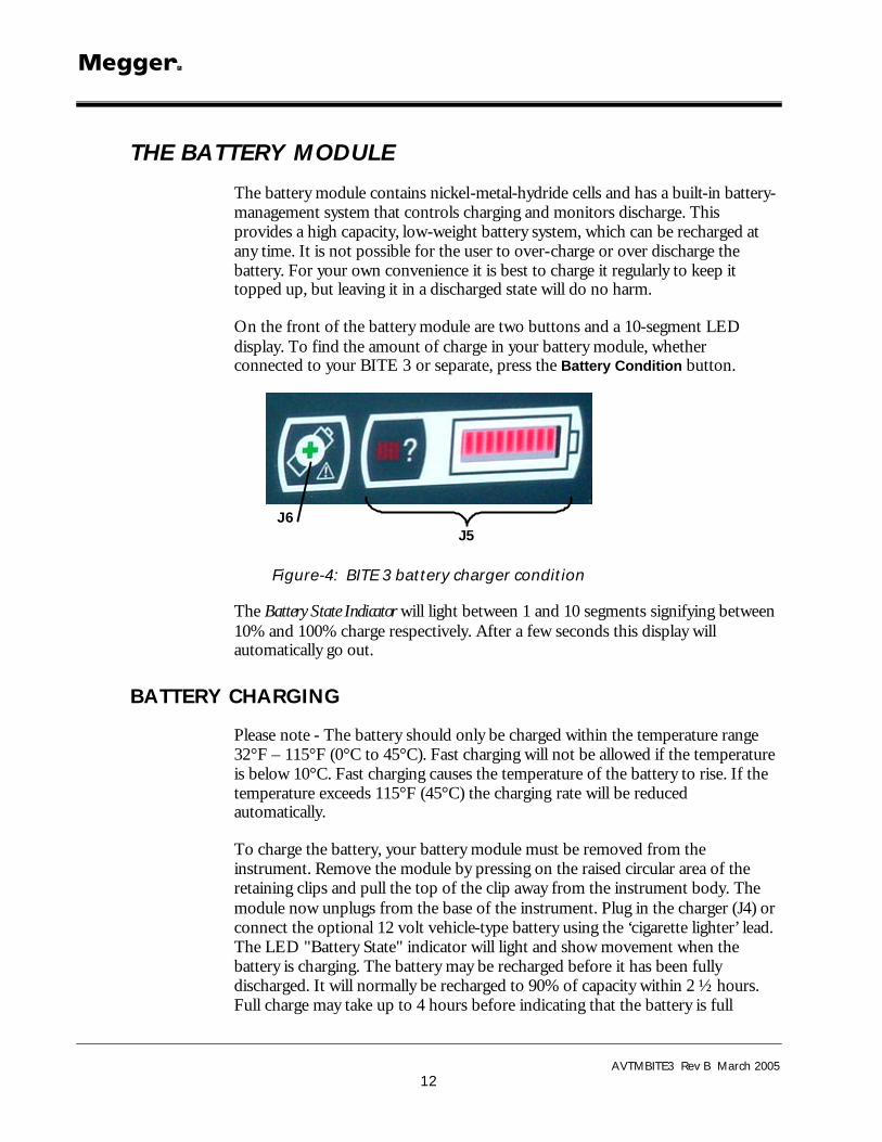
On the front of the battery module are two buttons and a 10-segment LED display. To find the amount of charge in your battery module, whether connected to your BITE 3 or separate, press the Battery Condition button.
J6 J5
Figure-4: BITE 3 battery charger condition
The Battery State Indicator will light between 1 and 10 segments signifying between 10% and 100% charge respectively. After a few seconds this display will automatically go out.
BATTERY CHARGING
Please note - The battery should only be charged within the temperature range 32°F – 115°F (0°C to 45°C). Fast charging will not be allowed if the temperature is below 10°C. Fast charging causes the temperature of the battery to rise. If the temperature exceeds 115°F (45°C) the charging rate will be reduced automatically.
To charge the battery, your battery module must be removed from the instrument. Remove the module by pressing on the raised circular area of the retaining clips and pull the top of the clip away from the instrument body. The module now unplugs from the base of the instrument. Plug in the charger (J4) or connect the optional 12 volt vehicle-type battery using the ‘cigarette lighter’ lead. The LED "Battery State" indicator will light and show movement when the battery is charging. The battery may be recharged before it has been fully discharged. It will normally be recharged to 90% of capacity within 2 ½ hours. Full charge may take up to 4 hours before indicating that the battery is full

Controls, Connectors, Indicators & Menus
AVTMBITE3 Rev B March 2005
13
depending on the initial state of the battery. When charging is complete the battery management circuitry will switch off so that over-charging is prevented.
Your battery module can be safely used in a partially charged state and will not suffer if stored in a discharged state. However, you may wish to have a spare battery that can be interchanged with the one in use to provide continuous use of your BITE 3.
As the battery ages, it may start to loose its capacity. In this case the battery module has a slow charge facility which is activated by pressing the Slow Charge (Ë) button (J6) while switching on the charger supply until the indicator bars start to move. This method of charging can take up to 48 hours and so is best reserved for a weekend or a period when the instrument is not required to be used. A fully charged battery, even if not used, will self discharge over a period of several weeks (faster at higher temperatures). Always check the "Battery State" indicator before starting work. A fully charged battery will light all segments. A fully discharged battery will light no segments.
NOTE: All batteries suffer a reduced life if exposed to constant high temperatures. A constant temperature of 30°C will probably cause the battery to fail in less than 5 years. 40°C will shorten its life to 2 years.
THE BATTERY STATE INDICATOR
The Battery State Indicator provides information on the amount of charge in the battery, but is also used to signal other conditions as follows:
Standard Charging (Fast): The battery module is charging at its standard rate. The LED is progressing across at a fast pace
Slow Charging (Slow): The battery module is charging at its slow rate. The LED is progressing at a slow pace
Standard charging but at a slow rate (Flashing and Slow): The battery has been set to charge at its standard rate but, because the battery has become hot, it has switched charge rates to a lower rate while the battery cools down. Wait for the temperature to drop and/or move to a cooler location. The stationary LEDs are flashing while one LED progresses at a slow pace.
Not charging. There is a temperature problem.
The battery is too hot or too cold and charging has therefore been interrupted until the battery returns to a temperature between 32°F and 115°F (0°C and 45°C). The stationary LEDs are flashing.

M
AVTMBITE3 Rev B March 2005
14
Input Voltage Too Low: The charger supply is not supplying sufficient voltage to the battery module to charge the batteries. The LED is progressing from right to left.
Battery nearly exhausted: The battery capacity is very low. Recharge it. The one remaining LED is flashing.
Error: Reset: An error has occurred within the battery module. The circuitry is resetting. Wait a few moments and the fault should clear. The first, fifth, sixth and tenth LEDs are flashing in unison.
Overvoltage problem: The charging supply voltage is too high. Disconnect the charger and rectify the fault. The LEDs will progress from outer LEDs to inner LEDs and vice versa.
F WARNING
Connecting to greater than 15 volts can cause permanent damage to the battery module.

AVTMBITE3 Rev B March 2005
15
4 TEST PROCEDURES
Overview
The BITE 3 is used to test a battery string while the dc system is on-line and floating. It can store measurements on a per cell/jar basis as well as per string basis. It has memory for about 22,000 60-cell strings in a database structure to keep track of all of the data. ProActiv is the tandem software package that keeps track of data and information about sites, strings and cells.
Using the BITE 3 to test a battery string involves the following steps:
1. Perform pre-test activities.
2. Turning on the BITE 3 and connecting the lead set.
3. Select a site/string and take measurements.
4. Perform post-test activities.
The BITE 3 uses a technique (patent application submitted) to eliminate the need for a CT under normal circumstances. Normally, the current in the cell/jar being measured must be measured to accurately calculate impedance (Z = E/I).
Optional lead sets are available to test different battery configurations. These optional lead sets include an “AMP/Burndy” lead set for testing batteries with harnesses using an AMP/Burndy style connector, a Quick Disconnect lead set for smaller batteries employing spade-type battery terminals (posts) and a Kelvin-style, spring clips for batteries with small, difficult-to-access posts. Tests using these lead sets are also described later in this chapter.
Step One: Perform Pre-Test Activities.
The best reproducible test data are obtained when the battery is floating.
1. Ensure the battery is floating and not being recharged or discharged.
2. Inspect all of the cells and intercell connections. Look for leaking cells, bulged cells or cells that are in a weakened state.

M
AVTMBITE3 Rev B March 2005
16
Step Two: Turning on the BITE 3 and Connecting the Lead Set.
The BITE 3 is a PC-based instrument running Windows CE. It will take about 30 seconds to boot up and be ready to take measurements.
1. Turn on the BITE 3 by pressing the on/off (O | I) button. The back light should stay lit.
2. Connect the lead set and, if used, the CT to the BITE 3.
3. a) Configure a new site and string (or download it from ProActiv).
Configure I Strings I New Enter New Str ing Information
Site:
String name:
Baseline: 1.00 mO
Warning: 15 ?
? %
Fail: 30 ?
? %
Change: 20 ?
? %
Deviation: 0 ?
? %
-or-
b) Select a site/string to be tested (See Chapter 3 for the flowchart of the menus.)
Measure I New Test
Select a String
? Site: I ?
? String: ?
Measure I New Test Select and Continue : a String Close
? Site: I ?
? String: ?
Test Procedures
AVTMBITE3 Rev B March 2005
17
Step Three: Select a Site/String and Take Measurements.
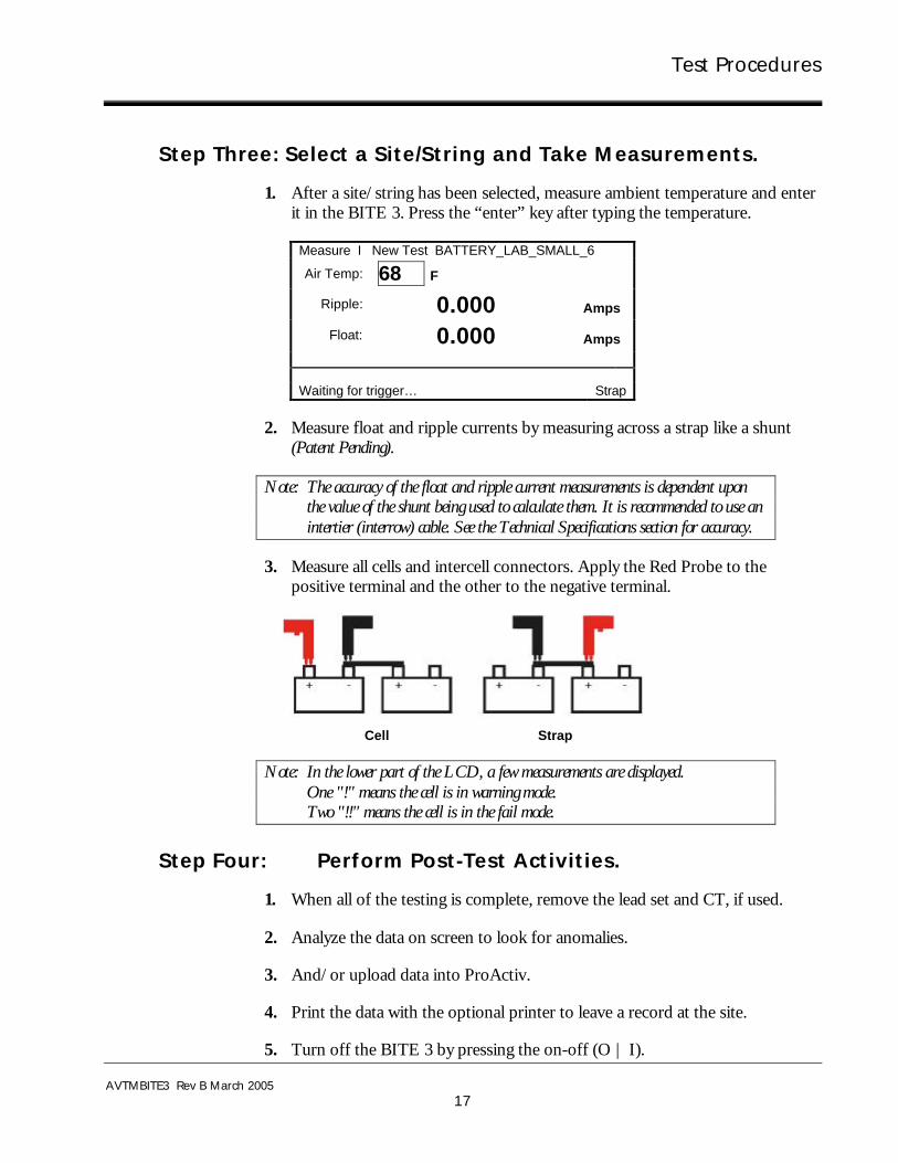
1. After a site/string has been selected, measure ambient temperature and enter it in the BITE 3. Press the “enter” key after typing the temperature.
Measure I New Test BATTERY_LAB_SMALL_6
Air Temp: 68 F Ripple: 0.000 Amps
Float: 0.000 Amps Waiting for trigger… Strap
2. Measure float and ripple currents by measuring across a strap like a shunt (Patent Pending).
Note: The accuracy of the float and ripple current measurements is dependent upon the value of the shunt being used to calculate them. It is recommended to use an intertier (interrow) cable. See the Technical Specifications section for accuracy.
3. Measure all cells and intercell connectors. Apply the Red Probe to the positive terminal and the other to the negative terminal.
Cell Strap
Note: In the lower part of the LCD, a few measurements are displayed. One "!" means the cell is in warning mode. Two "!!" means the cell is in the fail mode.
Step Four: Perform Post-Test Activities.
1. When all of the testing is complete, remove the lead set and CT, if used.
2. Analyze the data on screen to look for anomalies.
3. And/or upload data into ProActiv.
4. Print the data with the optional printer to leave a record at the site.
5. Turn off the BITE 3 by pressing the on-off (O | I).
M
AVTMBITE3 Rev B March 2005
18
Reviewing a Test
To review the readings, simply scroll up/down the screen. To return to testing, scroll to the last readings and start taking measurements.
Retesting a Cell/Jar or a Strap
To retest a cell/jar or a strap, simply scroll to that cell/jar or strap and press the right side of the cursor control pad. Retest the cell/jar or strap. To return to the normal test mode, press the left side of the cursor control pad and scroll to the last cell/jar or strap and continue testing.
Analyzing a Test (See Chapter 5)
Testing Noisy Battery Systems
The BITE 3 can be used to test noisy battery systems accurately. Set the (optional) CT for “impedance” mode. The BITE 3 will automatically use the noise in the battery system to take the impedance measurements. It works by using the system noise that causes a voltage drop in the battery. It simultaneously measures the system noise current in the battery that is causing the voltage drop. Impedance is then calculated as it normally is.
The procedure for testing noisy systems is simple. If a noisy system is encountered, the BITE 3 will display on the LCD a message, “Noise Detected”. This message indicates that better results may be obtained by using the optional CT in “Impedance” mode. Configure the CT mode in the BITE 3 for Impedance mode. Connect the CT to the BITE 3 and to any place within the string being tested. Then take the normal battery measurements as in Step Three above. The BITE 3 will now use the system noise in the battery instead of applying its own signal. It merely measures the voltage drop caused by the system noise while simultaneously measuring that current with the CT. Impedance is calculated accurately using the two measured parameters, voltage drop and current.
Tests Using Optional Lead Sets
1. Do Steps One and Two above.
2. Enter temperature & 8 .
3. Connect the lead set to the battery.
4. Depending upon the lead set, measure the float and ripple currents as in Step Three above, part 2 and pressing the red “test" start button.

Test Procedures
AVTMBITE3 Rev B March 2005
19
5. Continue testing cells and straps as necessary, making appropriate connections and pushing the red "test" button on the top panel of the BITE 3 to start the measurements.
6. Once the measurement is complete, continue testing until all cells/jars have been tested.
7. Follow Step Four, Perform Post-Test Activities from above.
Reviewing and retesting
Follow the same procedure as described above.

M
AVTMBITE3 Rev B March 2005
20
M

AVTMBITE3 Rev B March 2005
21
5 Interpreting Test Results
Overview
The BITE 3 interfaces with ProActiv to upload data and to download updates to sites and strings as well as the firmware in the instrument. ProActiv maintains data from all customers, regions, sites and strings whereas the BITE 3 manages a “subset” of these data and information. The on-board data analysis lists instantaneous results. The BITE 3 can also list percent change from the previous test and percent variation from the baseline if the previous test and baseline information have been downloaded from ProActiv. Baseline values can be manually entered into the BITE 3.
There are three modes to interpreting data: instantaneous, short-term and long-term trending. Instantaneous data interpretation is used when no previous data exist. In this mode, each cell is compared to the string average. The percent deviation should be within some relative limits as seen in the chart. As batteries age, the percent deviation will widen but in this mode, an outlier is the concern.
Viewing (Printing) Test Results on the LCD
When the testing has been completed, using the menu buttons, go to "Analyze/Site/String/Test Date" to select the test to be reviewed.
The screen will show the status of all cells/jars and straps. Any result outside of configured limits will be flagged. Results within the “pass” band will appear as normal text. Results within the “warning” band will appear as underlined text. Results in the “fail” band will appear as bold text.
Analyze BITE 3 Battery Analysis Report
BATTERY_LAB SMALL STRING Date: 2/28/2002 07:48 Temperature: 70.0F Float Current: 0.000A Ripple Current: 0.000A B/W/F/C: .131mO/15%//20%/3% # Z mO %v %D %C DC V R mO Time 1 .137 4.6 1.9 2.250 07:50 2 .132 .8 -1.8 2.250 07:50 3 .136 3.8 1.2 2.260 07:51 4 .134 2.3 .-.3 2.240 07:51 5 .137 4.6 1.9 2.250 07:51

M
AVTMBITE3 Rev B March 2005
22
These data can be printed using the optional printer. The printed format will be the same as that on the LCD. Connect the printer using the supplied RS-232 cable. Turn on the printer and follow the menus again, highlight “print” and press the enter key.
Instantaneous Mode of Analysis
If no previous data were measured, then a weak cell can only be found by comparing each cell against the string average, called deviation. The allowable percent deviation depends upon the battery technology: flooded Lead-acid or VRLA. Since a single cell can cause a battery failure, a single cell or two that is considerably higher than the rest of the string suggests that further investigation is warranted.
1 2 3 4 5
1 2 3 4 5 6 7 8
16 21 17 13 15 19 2 23 4 6 3

Interpreting Test Results
AVTMBITE3 Rev B March 2005
23
Short-term Mode of Analysis
In some cases, previous data were taken but doesn’t start at battery commissioning. In this scenario, a comparison between each cell and its previous measurement, called percent change, aids in determining its condition. Additionally, use the deviation as an additional piece of information to get a better determination of the condition of the string. See the Relative Limits chart for guidelines for allowable percent change.
Long-term Trending
When data have been taken since commissioning, trending is the best mode of analysis. This mode combines the trend over time, the percent change and percent deviation provides the most information about a battery’s state-of-health. See the Relative Limits chart for guidelines.
Relative Limits Chart Single Test Multiple Tests* Trending** % Deviation
from String Avg.
Cell's % Change
from Last Test
Cell's % Change
overall
Cell's % Change
from Last Test
Cell's % Change
overall
Lead-acid, Flooded 5 2 15 2 20
Lead-acid, VRLA, AGM 10 3 30 3 50
Lead-acid, VRLA, Gel 10 3 30 3 50
NiCd, Flooded 15 10 50 10 100
NiCd, Sealed 15 5 35 5 80
*For when data were not taken at installation ** For when data were taken at installation

M
AVTMBITE3 Rev B March 2005
24
M

AVTMBITE3 Rev B March 2005
25
6 Communicating with ProActiv
Overview
The BITE 3/ProActiv combination is a very powerful, easy-to-use data management and analysis tool. The BITE 3 is one of the easiest instruments to use. ProActiv is the database and analytical tool for a superior method of managing battery data. The on-board database of the BITE 3 allows the user to determine, while on-site, the condition of batteries. ProActiv allows a longer term view of the condition of batteries.
There are four aspects to the upload/download capabilities of the BITE 3 and ProActiv. The first one is the ability to configure the BITE 3 instrument settings such as date format, user-friendly name, decimal point format, etc. The second one is the ability to download Site and String information to the BITE 3. This simplifies the naming and configuring of the many sites and strings that will be tested so that the user will not have to configure these in the field. The third aspect is that the instrument’s firmware can be updated through the Internet. Firmware updates might include improvements and enhancements, fixes and additional languages. The last aspect is the upload of data from the BITE 3 to ProActiv.

M
AVTMBITE3 Rev B March 2005
26
Information & Settings
This screen is for configuring the various settings in the BITE 3. Once these settings are configured, the configuration can be saved to a file to download to other BITE 3s.

Communicating with ProActiv
AVTMBITE3 Rev B March 2005
27
String Information Export
This screen is for exporting site and string information and data to a BITE 3. With previous data in its memory, the BITE 3 can make comparisons to the immediate past data for each cell, called “percent change”.

M
AVTMBITE3 Rev B March 2005
28
Firmware Updates
The BITE 3 is designed to allow for updates to its firmware through either the Internet or a file using ProActiv. Simply open ProActiv, click on Instrument Utilities and then Firmware Updates. In the “Megger Instruments – Firmware Updates” window, click Acquire Updates and select either “from File(s)” or “Check for Updates (Internet)”. To see the version of firmware in the BITE 3 select “inquire” on the lower right-hand section of this window.

Communicating with ProActiv
AVTMBITE3 Rev B March 2005
29
Data and Information Export/Upload to a PC/Laptop
The BITE 3 can export data and site/string information to ProActiv.
A wizard opens to facilitate the importing of site and string information and battery data.

M
AVTMBITE3 Rev B March 2005
30
M
AVTMBITE3 Rev B March 2005
31
7 MAINTENANCE AND TROUBLE SHOOTING
Overview
The BITE 3 is designed to meet the rigors of battery testing in industrial environments. It is housed in a durable ABS/PS case as are the probes. It uses a WindowsTM CE operating system with on-board diagnostics. There is very little that can go wrong. There aren’t any user-serviceable parts in the instrument. But there are spares and extra parts available and are described in Appendix B.
Status LEDs
Lead Set
In order to aid in battery testing, status LEDs have been added to the probe handles with a redundant display on the LCD (for optional lead sets.) The chart below explains the status LEDs.
Red No Connection
Yellow- Blinking Connection detected, waiting for trigger
Yellow- Solid Connection found, measuring
Green Measuring complete, Okay to remove probes.
Battery
The battery used is a NiMH battery rated at 4.8Vdc and 7000mAh. It is designed to operate for two to four hours under heavy testing. It will fast-charge to 90% of rated capacity in one hour and fully charge in 24 hours. A button on the side will display the approximate capacity remaining (10% per bar).
As a safety feature the instrument is designed so that it can’t be used while the battery is charging.

M
AVTMBITE3 Rev B March 2005
32
Probe Tips
The probe tips are spring-loaded to break through oxide coatings and No-Ox greases to make a solid connection. Even though the tips are designed with ruggedness in mind, spare tips have been included with the instrument. Should a tip become damaged, simply pull, using pliers, the tip and replace it with a new one. The tip should be snug, not loose nor overly tight.
Printer (Optional)
Configuration
To print a paper copy of the existing printer settings:
While holding down the "On-Line" switch, turn on the printer. The following list will print (factory default settings shown).
Figure 5: Printer Configuration Printout

Maintenance and Trouble Shooting
AVTMBITE3 Rev B March 2005
33
If you want to leave the settings as they are, press the "FEED" switch.
If you need to change a setting, press the "ON LINE" switch to enter the reconfiguration mode. For each group of switches, press the "FEED" switch if all the settings are okay. Press the "ON LINE" switch if a setting needs to be changed. At an individual setting, press the "FEED" switch if it is okay and press "ON LINE" to change that setting.
If the BITE 3 Needs Repairs
Megger offers a complete repair service. Call Customer Service at 1-610-676-8500 to obtain an RMA number before shipment. Include all standard and optional accessories to ensure that all possible sources of problems can be investigated.
Ship to: Megger
Attn: Repair Dept, RMA #
Valley Forge Corporate Center
2621 Van Buren Avenue
Norristown, PA 19403 U.S.A.
610-676-8500
Please indicate all pertinent information regarding the problem or symptoms. Equipment returned for repair must be shipped prepaid and insured and marked to the attention of the Repair Dept. with the RMA clearly labeled.

M
AVTMBITE3 Rev B March 2005
34
M

AVTMBITE3 Rev B March 2005
35
APPENDIX A TECHNICAL SPECIFICATIONS
Electrical
Impedance Range and Resolution
0.05 to 1.000 mΩ 1 µΩ resolution
1 to 10.00 mΩ 10 µΩ resolution
10 to 100.0 mΩ 0.1 mΩ resolution
Voltage Range and Resolution
1 to 30 V dc across probes
1 to 8.0 V dc 1 mV resolution
8.0 to 30.00 V dc 10 mV resolution
Current Range and Resolution
Current: 0.5 – 9.99 A ac/dc 0.01 A resolution
10.0 – 99.9 A ac/dc 0.1 A resolution
Accuracy
dc voltage: (1% rdg +1 lsd)
ac impedance: (5% of rdg +1 lsd)
current: (5% rdg + 0.5 A)
Precision Better than 0.5% one sigma
Source Output Current: ½ A rms
Display: 1/4 VGA LCD
Settling Time per Reading: 3 seconds maximum
Battery Pack: 2-3 hours continuous
4.8V dc, 7000 mAh, quick charge NiMH battery pack

M
AVTMBITE3 Rev B March 2005
36
Environmental
Operating: 32° to 105° F (0° to +40° C)
Storage: -5° to 130° F (-20° to +55° C)
Humidity: 20 to 90% RH, noncondensing
Safety
Designed to meet IEC 61010-1 specifications
Mechanical
Dimensions: 8.6 W x 4 D x 9.5 H in.
220 H x 100 W x 240 D mm
Weight: 5.7 lbs (2.6 kg)
Charger
Supply Voltage
100 to 130 V, 50/60 Hz, 14 VA
210 to 250 V, 50/60 Hz, 14 VA
Output
6.50 V dc at 1.10 A dc charging (max.)
9.60 V dc open circuit
Optional Printer
Thermal, with 4.25 in. (110 mm) printing width
Battery-operated or line-operated

AVTMBITE3 Rev B March 2005
37
APPENDIX B - Replaceable Parts The BITE 3 as delivered includes all of the necessary basic accessories to test most battery configurations. However, the number of battery configurations is large. In order to satisfy many of the other battery configurations, a range of optional accessories is offered. They are listed here.
Description P/N
BITE 3 BITE 3
Including:
Carrying Case 35788
RS-232 Null modem cable 33533-1
Dual-point Lead set BI-10002
Tip Kit BI-10017
Line Charger EV6280-333
Battery EV6121-492
Manual AVTMBITE3
ProActiv BI-90001
Optional Accessories
Printer, battery-operated/110VAC 35755-3
Printer, battery-operated/220VAC 35755-4
Printer Paper 26999
AMP/Burndy Lead Set BI-10004
Kelvin Clip Lead set BI-10005
Quick Disconnect Lead set BI-10006
Cigarette Lighter Charger EV6280-332
Current Transformer Kit 35873
USB-Serial adapter 35871
Lighted Probe Extensions 35865
Spare Battery EV6121-492
Tip Kit BI-10017
Transit case, for soft-sided case 35915
Hard-sided carrying case 35890

M
AVTMBITE3 Rev B March 2005
38
M
![OpenOffice.org 2 · [0.21] [2005-10-02] [grs: 22nd Updated with Slackware installation ] [Rev A] [2005-10-12] [grs: Rev A – First non draft version ] [Rev.](https://static.fdocuments.in/doc/165x107/5be701ec09d3f246788bdd81/2-021-2005-10-02-grs-22nd-updated-with-slackware-installation-rev.jpg)