
AVR259: ATtiny40 QTouch ADC Demonstration...
28
APPLICATION NOTE AVR259: ATtiny40 QTouchADC Demonstration Kit Atmel QTouch Description The reference design is to demonstrate capabilities of the Atmel ® ATtiny40, which supports QTouchADC method. The technology requires only a single I/O pin per touch channel. The reference design supports two analog output channels using PWM, buzzer, and LEDs indicating touch, and TWI or SPI communication interfaces. It also allows complete configurability, and supports off-board QTouch ® sensors. The application note includes firmware supporting eight keys, TWI slave interface (I 2 C compatible), buzzer, and LED control. Features Up to 12 Atmel QTouchADC channels Single I/O pin per channel TWI (Philips I 2 C Compatible) interface SPI interface Two analog outputs (PWM) Buzzer LEDs Supports QT TM 600 Touch Debug interface TPI programming interface Powered from USB or external supply Figure 1. ATtiny40 QTouchADC Reference Design Atmel-8332C-ATtiny40-QTouchADC-Demonstration-Kit-ApplicationNote_AVR259_082014
-
Upload
trinhquynh -
Category
Documents
-
view
222 -
download
3
Transcript of AVR259: ATtiny40 QTouch ADC Demonstration...

APPLICATION NOTE
AVR259: ATtiny40 QTouchADC Demonstration Kit
Atmel QTouch
Description
The reference design is to demonstrate capabilities of the Atmel® ATtiny40, which
supports QTouchADC method. The technology requires only a single I/O pin per
touch channel. The reference design supports two analog output channels using
PWM, buzzer, and LEDs indicating touch, and TWI or SPI communication
interfaces. It also allows complete configurability, and supports off-board QTouch®
sensors.
The application note includes firmware supporting eight keys, TWI slave interface
(I2C compatible), buzzer, and LED control.
Features
Up to 12 Atmel QTouchADC channels
Single I/O pin per channel
TWI (Philips I2C Compatible) interface
SPI interface
Two analog outputs (PWM)
Buzzer
LEDs
Supports QTTM
600 Touch Debug interface
TPI programming interface
Powered from USB or external supply
Figure 1. ATtiny40 QTouchADC Reference Design
Atmel-8332C-ATtiny40-QTouchADC-Demonstration-Kit-ApplicationNote_AVR259_082014

AVR259: ATtiny40 QTouchADC Demonstration Kit [APPLICATION NOTE] Atmel-8332C-ATtiny40-QTouchADC-Demonstration-Kit-ApplicationNote_AVR259_082014 2
2
Table of Contents
1 Hardware … ................................................................................................................. 4
1.1 QTouchADC .......................................................................................................................................... 4
1.2 Analog Channels ................................................................................................................................... 6
1.2.1 PWM Input ................................................................................................................................ 7
1.2.2 Analog Output ........................................................................................................................... 7
1.3 Buzzer … ............................................................................................................................................ 7
1.4 LEDs … ............................................................................................................................................ 7
1.5 Communication Interface ...................................................................................................................... 7
1.6 Power Supply ........................................................................................................................................ 7
1.6.1 Power Options .......................................................................................................................... 7
1.6.1.1 USB Connector ......................................................................................................... 7
1.6.1.2 On-board Regulator .................................................................................................. 7
1.6.1.3 External Supply......................................................................................................... 8
1.6.2 Power Supply Considerations ................................................................................................... 8
2 Programming and Debugging .................................................................................... 9
2.1 TPI Programming .................................................................................................................................. 9
2.1.1 Programmers for TPI Programming .......................................................................................... 9
2.2 Debugging ............................................................................................................................................. 9
3 Firmware ................................................................................................................... 10
3.1 User Application Code ......................................................................................................................... 10
3.1.1 User Application Requirements .............................................................................................. 10
3.1.2 Application Code Flow ............................................................................................................ 11
3.2 TWI Interface Operation ...................................................................................................................... 12
3.2.1 Data Read .............................................................................................................................. 13
3.2.2 SDA, SCL ............................................................................................................................... 13
3.2.3 IRQ Line ................................................................................................................................. 13
3.3 Analog Interface Operation ................................................................................................................. 13
3.4 Buzzer and LED Operation ................................................................................................................. 15
3.5 Pin Mapping ........................................................................................................................................ 15
4 QT600 Touch Debug Interface .................................................................................. 16
Appendix A ................................................................................................................... 18
A.1 Atmel QTouch Library ......................................................................................................................... 18
A.2 Application Programming Interface ..................................................................................................... 18
A.2.1 Manifest Constants ................................................................................................................. 18
A.2.2 Type Definitions ...................................................................................................................... 18
A.2.3 Structs .................................................................................................................................... 19
A.2.4 Enumerations ......................................................................................................................... 19
A.2.5 Global Touch Sensing Status ................................................................................................. 20
A.2.6 Global touch Sensing Configuration ....................................................................................... 20
A.2.7 Touch Sensing Data ............................................................................................................... 20
A.2.8 Hook for User Functions ......................................................................................................... 20
A.2.9 Configuring Sensors ............................................................................................................... 21
A.2.9.1 Configuration Functions .......................................................................................... 21
A.2.9.2 qt_enable_key() ...................................................................................................... 21
A.2.10 Measuring and checking Touch Status ................................................................................... 21

AVR259: ATtiny40 QTouchADC Demonstration Kit [APPLICATION NOTE] Atmel-8332C-ATtiny40-QTouchADC-Demonstration-Kit-ApplicationNote_AVR259_082014
3
3
A.2.10.1 Touch Status Functions .......................................................................................... 21
A.2.10.2 Additional Sensing Commands ............................................................................... 21
A.2.10.3 qt_init_sensing() ..................................................................................................... 21
A.2.10.4 qt_measure_sensors() ............................................................................................ 22
A.2.10.5 qt_calibrate_sensing() ............................................................................................ 22
A.2.10.6 qt_reset_sensing() .................................................................................................. 22
A.3 Schematic ........................................................................................................................................... 23
A.4 PCB .............................................................................................................................................. 24
A.5 BOM .............................................................................................................................................. 25
A.6 References .......................................................................................................................................... 26
A.7 Revision History .................................................................................................................................. 27

AVR259: ATtiny40 QTouchADC Demonstration Kit [APPLICATION NOTE] Atmel-8332C-ATtiny40-QTouchADC-Demonstration-Kit-ApplicationNote_AVR259_082014 4
4
1 Hardware
The reference design can support up to twelve QTouchADC Keys, and has provision to hook-up off-board touch
keys. The QTouchADC technology requires only one I/O pin per channel, and do not require any external
sampling capacitors. The sensor channels are on the ADC pins.
The two analog channels are controlled via PWM from Atmel ATtiny40. These channels provide analog values
when the corresponding key is touched. This is ideal to replace an existing tactile switch (resistive-ladder) TV
control keyboard, or for any other application which does not require a communication interface to indicate a key
touch or release. The buzzer and LEDs can be configured to provide an indication on power up or key
touched/released status.
Figure 1-1. System Block Diagram
1.1 QTouchADC
The QTouchADC method requires ADC for touch measurement. For the capacitive measurement, the touch
channels should be on the ADC pins. The ADC module should be released for touch library operation by the user
application. The library will internally back up the user setting of ADC, reconfigure it for touch measurement, and
once the measurements of all the channels are completed, restore the backed up registers.
The acquisition is very fast, typically in the range 100µs to 300µs per channel at 4MHz. The acquisition method is
single channel at a time.
AVR259: ATtiny40 QTouchADC Demonstration Kit [APPLICATION NOTE] Atmel-8332C-ATtiny40-QTouchADC-Demonstration-Kit-ApplicationNote_AVR259_082014
5
5
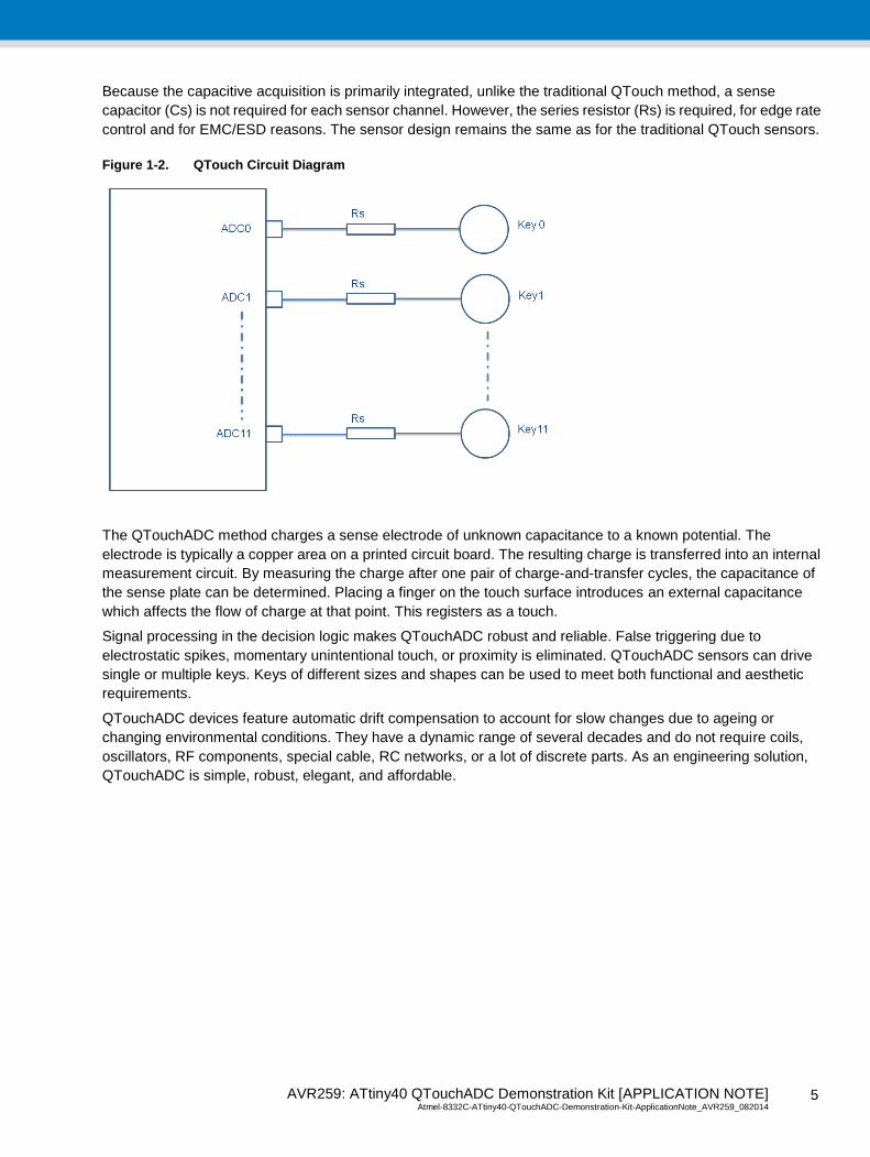
Because the capacitive acquisition is primarily integrated, unlike the traditional QTouch method, a sense
capacitor (Cs) is not required for each sensor channel. However, the series resistor (Rs) is required, for edge rate
control and for EMC/ESD reasons. The sensor design remains the same as for the traditional QTouch sensors.
Figure 1-2. QTouch Circuit Diagram
The QTouchADC method charges a sense electrode of unknown capacitance to a known potential. The
electrode is typically a copper area on a printed circuit board. The resulting charge is transferred into an internal
measurement circuit. By measuring the charge after one pair of charge-and-transfer cycles, the capacitance of
the sense plate can be determined. Placing a finger on the touch surface introduces an external capacitance
which affects the flow of charge at that point. This registers as a touch.
Signal processing in the decision logic makes QTouchADC robust and reliable. False triggering due to
electrostatic spikes, momentary unintentional touch, or proximity is eliminated. QTouchADC sensors can drive
single or multiple keys. Keys of different sizes and shapes can be used to meet both functional and aesthetic
requirements.
QTouchADC devices feature automatic drift compensation to account for slow changes due to ageing or
changing environmental conditions. They have a dynamic range of several decades and do not require coils,
oscillators, RF components, special cable, RC networks, or a lot of discrete parts. As an engineering solution,
QTouchADC is simple, robust, elegant, and affordable.
AVR259: ATtiny40 QTouchADC Demonstration Kit [APPLICATION NOTE] Atmel-8332C-ATtiny40-QTouchADC-Demonstration-Kit-ApplicationNote_AVR259_082014 6
6
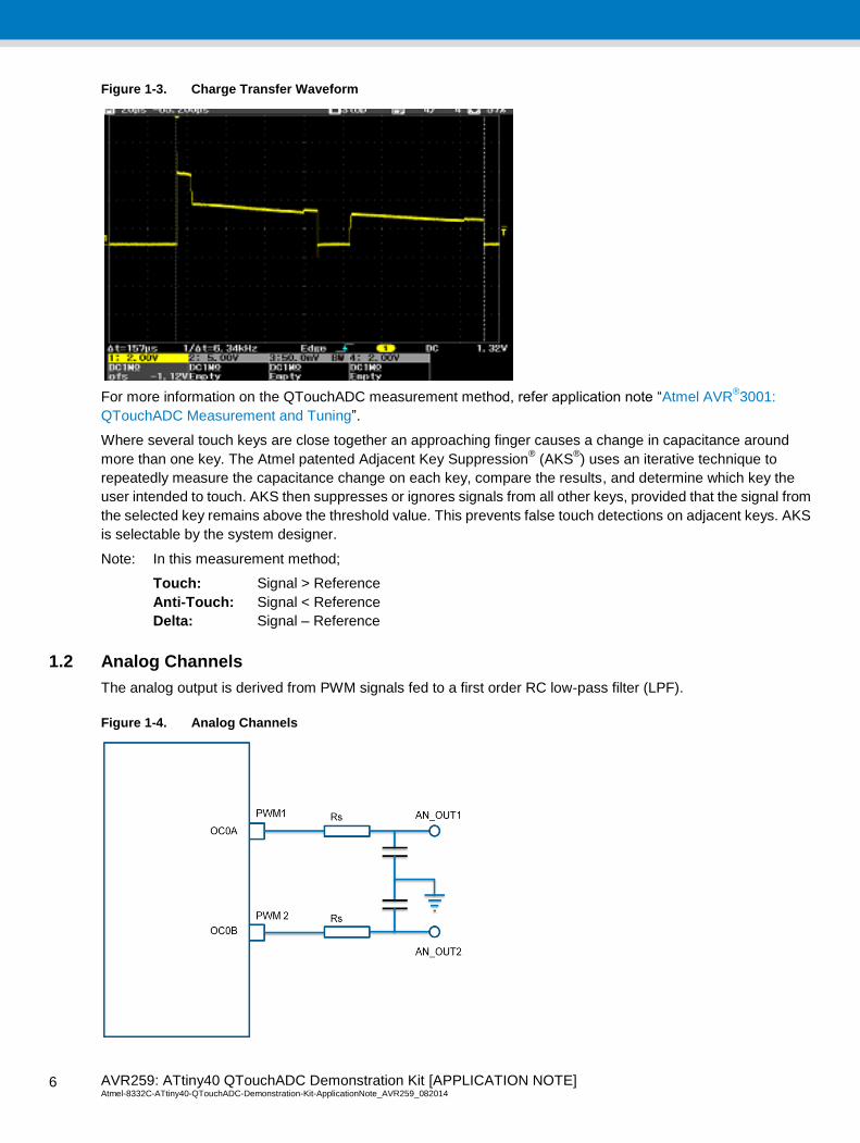
Figure 1-3. Charge Transfer Waveform
For more information on the QTouchADC measurement method, refer application note “Atmel AVR®3001:
QTouchADC Measurement and Tuning”.
Where several touch keys are close together an approaching finger causes a change in capacitance around
more than one key. The Atmel patented Adjacent Key Suppression® (AKS
®) uses an iterative technique to
repeatedly measure the capacitance change on each key, compare the results, and determine which key the
user intended to touch. AKS then suppresses or ignores signals from all other keys, provided that the signal from
the selected key remains above the threshold value. This prevents false touch detections on adjacent keys. AKS
is selectable by the system designer.
Note: In this measurement method;
Touch: Signal > Reference
Anti-Touch: Signal < Reference
Delta: Signal – Reference
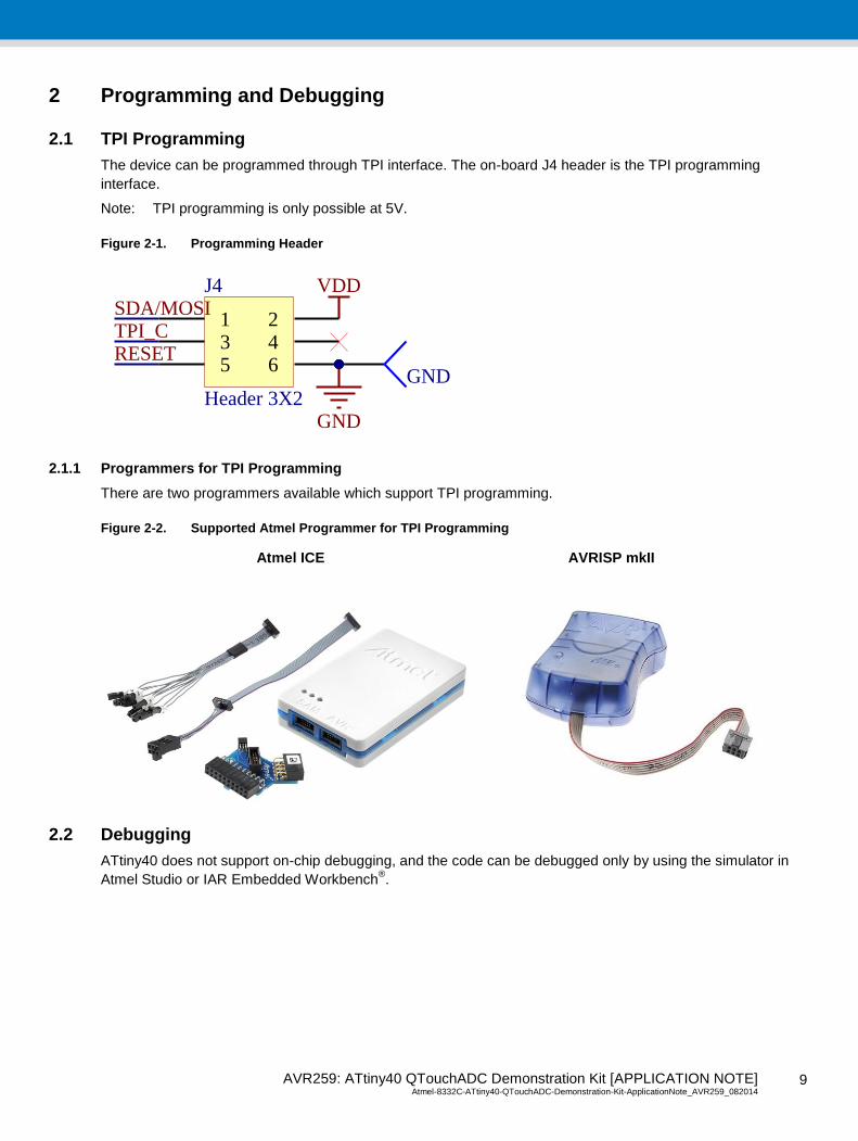
1.2 Analog Channels
The analog output is derived from PWM signals fed to a first order RC low-pass filter (LPF).
Figure 1-4. Analog Channels

AVR259: ATtiny40 QTouchADC Demonstration Kit [APPLICATION NOTE] Atmel-8332C-ATtiny40-QTouchADC-Demonstration-Kit-ApplicationNote_AVR259_082014
7
7
1.2.1 PWM Input
PWM_IN1 and PWM_IN2 are default driven by the OC0A (PC0) and OC0B (PA5) pins of ATtiny40, respectively.
Optionally, they can be driven by any other ATtiny40 pin or an external source via connecting to the PWM_IN1 or
PWM_IN2 test points.
1.2.2 Analog Output
Test points are provided on the board to tap the analog output. It can be fed to an external buffer or voltage
follower to drive a low-impedance load.
1.3 Buzzer
The on-board buzzer can be used as a user alert such as for annunciation on any key touch/release event. The
board includes external driver circuit to drive a buzzer. The buzzer is driven by default by PB1 pin of ATtiny40.
Optionally it can be driven by any other ATtiny40 pin or external source via connecting to Pin3 on the J6 header.
1.4 LEDs
LED1 and LED2 are controlled by default by PB2 and PB3 of ATtiny40, respectively. But similar to the buzzer, it
can be driven by any other ATtiny40 pin or external source via connecting to Pin2 or Pin1 on the J6 header. The
on-board LED drive circuit will help in testing with high current LEDs such as some White LEDs.
1.5 Communication Interface
The communication interface has the TWI and SPI lines available on the J5 header. The header layout is
compatible with QT600 touch debug interface.
Figure 1-5. Communication Interface Header
1.6 Power Supply
1.6.1 Power Options
1.6.1.1 USB Connector
5V power can be conveniently provided to the board via the USB connector.
1.6.1.2 On-board Regulator
A linear drop-out regulator can be mounted on board (U1) to derive regulated power for the ATtiny40/Touch
Interface. The external loads, such as the LEDs and buzzer, are not powered by this regulated voltage.
1 23 45 67 89 10
J5
Header 5X2
GNDVDD
GND
SDA/MOSI SCL/SCK
SDA/MOSISCL/SCKMISO
GND

AVR259: ATtiny40 QTouchADC Demonstration Kit [APPLICATION NOTE] Atmel-8332C-ATtiny40-QTouchADC-Demonstration-Kit-ApplicationNote_AVR259_082014 8
8
Suggested regulators are;
Torex (XC6215 series) or
Seiko (S817 series) or
BCD Semi (AP2121 series)
1.6.1.3 External Supply
Test points are provided on board to supply external power in the range 1.8V - 5V.
1.6.2 Power Supply Considerations
If the power supply varies slowly with the temperature, the device will track and compensate for these changes
automatically with only minor changes in sensitivity. If the supply voltage fluctuates or shifts quickly, the drift
compensation mechanism will not be able to keep up, causing sensitivity anomalies or false detections.
As the device uses the power supply itself as an analog reference, the power should be very clean and come
from a separate regulator. A standard, inexpensive low- dropout (LDO) type regulator should be used, and
should not also be used to power other loads such as LEDs, relays, or other high-current devices. Load shifts on
the output of the LDO can cause VCC to fluctuate enough to cause false detection or sensitivity shifts.
A regulator IC shared with other logic devices can result in erratic operation, and is not
advised.
A single ceramic 0.1µF bypass capacitor with short traces should be placed very close to the supply pins. It is
recommended that supply ripple and noise should not be more than ±25mV for a 5V supply.
AVR259: ATtiny40 QTouchADC Demonstration Kit [APPLICATION NOTE] Atmel-8332C-ATtiny40-QTouchADC-Demonstration-Kit-ApplicationNote_AVR259_082014
9
9
2 Programming and Debugging
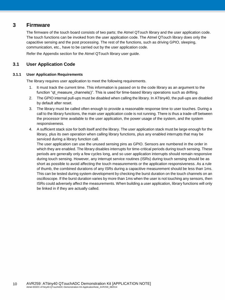
2.1 TPI Programming
The device can be programmed through TPI interface. The on-board J4 header is the TPI programming
interface.
Note: TPI programming is only possible at 5V.
Figure 2-1. Programming Header
2.1.1 Programmers for TPI Programming
There are two programmers available which support TPI programming.
Figure 2-2. Supported Atmel Programmer for TPI Programming
Atmel ICE AVRISP mkII
2.2 Debugging
ATtiny40 does not support on-chip debugging, and the code can be debugged only by using the simulator in
Atmel Studio or IAR Embedded Workbench®.
VDD
1 23 45 6
J4
Header 3X2GND
TPI_CSDA/MOSI
RESETGND
AVR259: ATtiny40 QTouchADC Demonstration Kit [APPLICATION NOTE] Atmel-8332C-ATtiny40-QTouchADC-Demonstration-Kit-ApplicationNote_AVR259_082014 1
0
10
3 Firmware
The firmware of the touch board consists of two parts; the Atmel QTouch library and the user application code.
The touch functions can be invoked from the user application code. The Atmel QTouch library does only the
capacitive sensing and the post processing. The rest of the functions, such as driving GPIO, sleeping,
communication, etc., have to be carried out by the user application code.
Refer the Appendix section for the Atmel QTouch library user guide.
3.1 User Application Code
3.1.1 User Application Requirements
The library requires user application to meet the following requirements.
1. It must track the current time. This information is passed on to the code library as an argument to the
function “qt_measure_channels()”. This is used for time-based library operations such as drifting.
2. The GPIO internal pull-ups must be disabled when calling the library. In ATtiny40, the pull-ups are disabled
by default after reset.
3. The library must be called often enough to provide a reasonable response time to user touches. During a
call to the library functions, the main user application code is not running. There is thus a trade-off between
the processor time available to the user application, the power usage of the system, and the system
responsiveness.
4. A sufficient stack size for both itself and the library. The user application stack must be large enough for the
library, plus its own operation when calling library functions, plus any enabled interrupts that may be
serviced during a library function call.
The user application can use the unused sensing pins as GPIO. Sensors are numbered in the order in
which they are enabled. The library disables interrupts for time-critical periods during touch sensing. These
periods are generally only a few cycles long, and so user application interrupts should remain responsive
during touch sensing. However, any interrupt service routines (ISRs) during touch sensing should be as
short as possible to avoid affecting the touch measurements or the application responsiveness. As a rule
of thumb, the combined durations of any ISRs during a capacitive measurement should be less than 1ms.
This can be tested during system development by checking the burst duration on the touch channels on an
oscilloscope. If the burst duration varies by more than 1ms when the user is not touching any sensors, then
ISRs could adversely affect the measurements. When building a user application, library functions will only
be linked in if they are actually called.

AVR259: ATtiny40 QTouchADC Demonstration Kit [APPLICATION NOTE] Atmel-8332C-ATtiny40-QTouchADC-Demonstration-Kit-ApplicationNote_AVR259_082014
11
11
3.1.2 Application Code Flow
Figure 3-1. Flow Chart
The system initialization consists of initializing the MCU ports by appropriately setting the data direction
registers, setting the initial PWM output to inactive high, initializing the global variables, and enabling the
TWI interface or the debug interface

AVR259: ATtiny40 QTouchADC Demonstration Kit [APPLICATION NOTE] Atmel-8332C-ATtiny40-QTouchADC-Demonstration-Kit-ApplicationNote_AVR259_082014 1
2
12
The Atmel QTouch Library is initialized by enabling keys on the appropriate channels by calling
“qt_enable_key()”, and setting the thresholds, hysteresis, and AKS groups. All the keys are in different
AKS groups.
The user application calls “qt_measure_sensors()” to measure all the enabled channels
If there is a change in the sensor states, then the IRQ line will be asserted low and the sensor state will be
copied to the TWI buffer
When there is a change in the sensor state, the buzzer will be switched on for 30ms. The PWM output is
held at steady low, and the buzzer is turned on by generating a 4kHz square wave.
After 30ms, the buzzer is turned off, and if the sensor is touched, a PWM signal is generated on the analog
output pin corresponding to the key touched, as long as the key is touched
The LED is also switched on when the sensor is touched, and switched off when the sensor is released
The respective ISRs will take care of TWI, PWM, and current time tracking
If it is time to measure, continue from qt_measure_sensors()
3.2 TWI Interface Operation
The TWI interface is I2C and SMBUS compatible. The TWI module in ATtiny40 implements slave functionality
only. Lost arbitration, errors, collisions, and clock holds on the bus are detected in hardware and indicated. The
slave logic continues to operate in all sleep modes, including power down.
The code implemented in this application note is a custom TWI slave driver for this touch application.
The slave driver C code consists of two files:
TWI_Slave.c
TWI_Slave.h
The main.c file contains an example of how to use the driver. The TWI_Slave.h file must be included in the main
application, and contains all function declarations and defines for all TWI status codes. The TWI status code
defines can be used to evaluate error messages and take appropriate actions. The TWI_Slave.c file contains all
the driver functions.
Some devices have an additional TWI Address mask register (TWAMR) which enables a device to respond to
several TWI slave addresses. A customized version of the standard implementation described here is included in
the application note attachment.
Table 3-1. TWI Slave Driver Functions
Function Description
TWI_slave_initialise()
Call this function to set up the TWI slave to its initial standby state. All the TWI interrupts are
enabled. Remember to enable global interrupts from the main application after initializing the
TWI. The slave address is defined in the TWI_Slave.h file.
#define TWI_ADDR 0x10
TWI_touch_status()
Call this function to copy the touch sensor status to the TWI buffer to be sent out.
The IRQ line will be asserted low to intimate master a change in the status.
__interrupt void TWI_ISR()
This is the interrupt service routine (ISR) function, and is automatically called when the TWI
interrupt is triggered; that is, whenever a TWI event has occurred. This function should not be
called directly from the main application. The TWI ISR will take care of the TWI state ma-
chine’s sending the TWI buffer and receiving the address location from the master.
TWI_bus_error_check ()
Call this function to check when an illegal bus condition has occurred during a transfer and
rectify it.

AVR259: ATtiny40 QTouchADC Demonstration Kit [APPLICATION NOTE] Atmel-8332C-ATtiny40-QTouchADC-Demonstration-Kit-ApplicationNote_AVR259_082014
13
13
3.2.1 Data Read
The sequence of events to read data from the device is as shown in Table 3-2:
Table 3-2. TWI Byte Format
S SLA+W A MemAddress A Sr SLA+R A Data 1 A Data n /A P
MASTER; SLAVE;
The host initiates the transfer by sending the START condition, and follows this by sending the slave address of
the device together with the write bit. The device sends an ACK. The host then sends the memory address within
the device it wishes to read from. The device sends an ACK.
The host must then send a repeated START condition followed by the slave address again, but this time
accompanied by the read bit. The device will return either an ACK or NACK. If the host returns an ACK, the
device will subsequently transmit the data byte from the next address. Each time a data byte is transmitted, the
device automatically increments the internal address. The device will continue to return data bytes until the host
responds with a NACK. The host should terminate the transfer by issuing the STOP condition.
Table 3-3. Communication Bytes
Address Use Access
0 Board ID Read
1 Firmware version Read
2 Sensor status Read
3.2.2 SDA, SCL
The pins are open-drain, and so the devices can only pull these lines low or release them open. The termination
resistors pull the line up to VDD if no device is pulling it down.
The termination resistors commonly range from 1kΩ to 10kΩ.
3.2.3 IRQ Line
The IRQ line is an active-low line, and will be asserted low when there is a change in the sensor state. The IRQ
line will be reset when at least one byte is placed on the TWI bus to be transferred.
3.3 Analog Interface Operation
The board can communicate the touch status to the host controller via different analog steady state voltages for
respective keys. The analog output is RC filtered PWM signal generated from the MCU. Table 3-4 lists the
various analog output voltages for a supply voltage of 5V.
Table 3-4. Analog Values for each Key
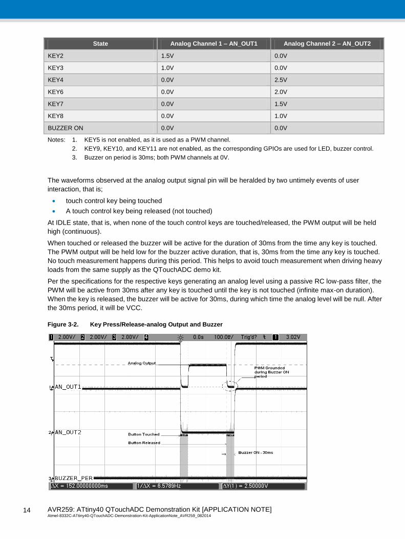
State Analog Channel 1 – AN_OUT1 Analog Channel 2 – AN_OUT2
IDLE 5.0V 5.0V
KEY0 2.5V 0.0V
KEY1 2.0V 0.0V
AVR259: ATtiny40 QTouchADC Demonstration Kit [APPLICATION NOTE] Atmel-8332C-ATtiny40-QTouchADC-Demonstration-Kit-ApplicationNote_AVR259_082014 1
4
14
State Analog Channel 1 – AN_OUT1 Analog Channel 2 – AN_OUT2
KEY2 1.5V 0.0V
KEY3 1.0V 0.0V
KEY4 0.0V 2.5V
KEY6 0.0V 2.0V
KEY7 0.0V 1.5V
KEY8 0.0V 1.0V
BUZZER ON 0.0V 0.0V
Notes: 1. KEY5 is not enabled, as it is used as a PWM channel.
2. KEY9, KEY10, and KEY11 are not enabled, as the corresponding GPIOs are used for LED, buzzer control.
3. Buzzer on period is 30ms; both PWM channels at 0V.
The waveforms observed at the analog output signal pin will be heralded by two untimely events of user
interaction, that is;
touch control key being touched
A touch control key being released (not touched)
At IDLE state, that is, when none of the touch control keys are touched/released, the PWM output will be held
high (continuous).
When touched or released the buzzer will be active for the duration of 30ms from the time any key is touched.
The PWM output will be held low for the buzzer active duration, that is, 30ms from the time any key is touched.
No touch measurement happens during this period. This helps to avoid touch measurement when driving heavy
loads from the same supply as the QTouchADC demo kit.
Per the specifications for the respective keys generating an analog level using a passive RC low-pass filter, the
PWM will be active from 30ms after any key is touched until the key is not touched (infinite max-on duration).
When the key is released, the buzzer will be active for 30ms, during which time the analog level will be null. After
the 30ms period, it will be VCC.
Figure 3-2. Key Press/Release-analog Output and Buzzer
AVR259: ATtiny40 QTouchADC Demonstration Kit [APPLICATION NOTE] Atmel-8332C-ATtiny40-QTouchADC-Demonstration-Kit-ApplicationNote_AVR259_082014
15
15
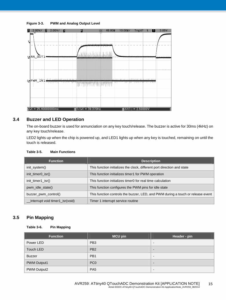
Figure 3-3. PWM and Analog Output Level
3.4 Buzzer and LED Operation
The on-board buzzer is used for annunciation on any key touch/release. The buzzer is active for 30ms (4kHz) on
any key touch/release.
LED2 lights up when the chip is powered up, and LED1 lights up when any key is touched, remaining on until the
touch is released.
Table 3-5. Main Functions
Function Description
init_system() This function initializes the clock, different port direction and state
init_timer0_isr() This function initializes timer1 for PWM operation
init_timer1_isr() This function initializes timer0 for real time calculation
pwm_idle_state() This function configures the PWM pins for idle state
buzzer_pwm_control() This function controls the buzzer, LED, and PWM during a touch or release event
__interrupt void timer1_isr(void) Timer 1 interrupt service routine
3.5 Pin Mapping
Table 3-6. Pin Mapping
Function MCU pin Header - pin
Power LED PB3 -
Touch LED PB2 -
Buzzer PB1 -
PWM Output1 PC0 -
PWM Output2 PA5 -
AVR259: ATtiny40 QTouchADC Demonstration Kit [APPLICATION NOTE] Atmel-8332C-ATtiny40-QTouchADC-Demonstration-Kit-ApplicationNote_AVR259_082014 1
6
16
Function MCU pin Header - pin
SDA PC4 J5-Pin1
SCL PC1 J5-Pin2
IRQ PC2 J5-Pin7
MOSI* PC4 J5-Pin6
SCK* PC1 J5-Pin8
Note: QT600 Touch Debug Interface. TWI disabled.
4 QT600 Touch Debug Interface
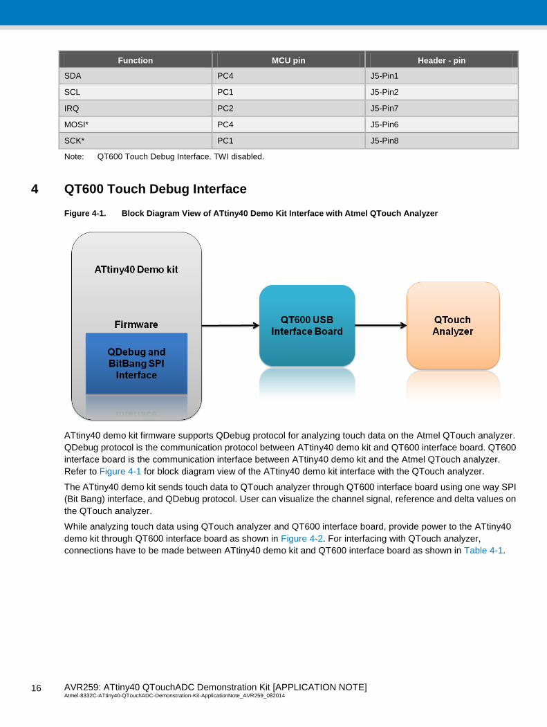
Figure 4-1. Block Diagram View of ATtiny40 Demo Kit Interface with Atmel QTouch Analyzer
ATtiny40 demo kit firmware supports QDebug protocol for analyzing touch data on the Atmel QTouch analyzer.
QDebug protocol is the communication protocol between ATtiny40 demo kit and QT600 interface board. QT600
interface board is the communication interface between ATtiny40 demo kit and the Atmel QTouch analyzer.
Refer to Figure 4-1 for block diagram view of the ATtiny40 demo kit interface with the QTouch analyzer.
The ATtiny40 demo kit sends touch data to QTouch analyzer through QT600 interface board using one way SPI
(Bit Bang) interface, and QDebug protocol. User can visualize the channel signal, reference and delta values on
the QTouch analyzer.
While analyzing touch data using QTouch analyzer and QT600 interface board, provide power to the ATtiny40
demo kit through QT600 interface board as shown in Figure 4-2. For interfacing with QTouch analyzer,
connections have to be made between ATtiny40 demo kit and QT600 interface board as shown in Table 4-1.

AVR259: ATtiny40 QTouchADC Demonstration Kit [APPLICATION NOTE] Atmel-8332C-ATtiny40-QTouchADC-Demonstration-Kit-ApplicationNote_AVR259_082014
17
17
Table 4-1. Connections between ATtiny40 Demo Kit and QT600 USB Interface Board
Interface
ATtiny40 Demonstration Kit
(J5 Connector)
QT600 Interface Board
(TOUCH DATA Connector)
One way SPI
(BitBang)
GND (TEST POINT) SS (PIN 5)
MOSI (PIN 6) MOSI (PIN 6)
SCK (PIN 8) SCK (PIN 8)
GND (PIN 9) GND( PIN 9)
VDD (PIN 10) VDD (PIN 10)
Note: In QT600 debug interface mode;
1. TWI is disabled in the firmware.
2. While analyzing touch data, power up the ATtiny40 demo kit using QT600 interface board.
Figure 4-2. ATtiny40 Demo Kit interfaced with QT600 Interface Board
Note: The firmware consists of two configuration modes. The first one is release mode and the second one is
debug mode.
Release mode supports both TWI interface operation and QT600 touch debug interface operation. By default
TWI interface operation is enabled. For enabling QT600 touch debug interface operation, “TWI_INTERFACE”
macro has to be disabled under C compiler - Preprocessor section of project options.
Debug mode supports both QT600 touch debug interface operation and the code debugging (using the simulator
in Atmel Studio). In Debug mode, TWI interface is disabled.
AVR259: ATtiny40 QTouchADC Demonstration Kit [APPLICATION NOTE] Atmel-8332C-ATtiny40-QTouchADC-Demonstration-Kit-ApplicationNote_AVR259_082014 1
8
18
Appendix A
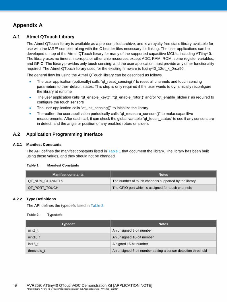
A.1 Atmel QTouch Library
The Atmel QTouch library is available as a pre-compiled archive, and is a royalty free static library available for
use with the IAR™ compiler along with the C header files necessary for linking. The user applications can be
developed on top of the Atmel QTouch library for many of the supported capacitive MCUs, including ATtiny40.
The library uses no timers, interrupts or other chip resources except ADC, RAM, ROM, some register variables,
and GPIO. The library provides only touch sensing, and the user application must provide any other functionality
required. The Atmel QTouch library used for the existing firmware is libtiny40_12qt_k_0rs.r90.
The general flow for using the Atmel QTouch library can be described as follows.
The user application (optionally) calls “qt_reset_sensing()” to reset all channels and touch sensing
parameters to their default states. This step is only required if the user wants to dynamically reconfigure
the library at runtime
The user application calls “qt_enable_key()”, “qt_enable_rotor()” and/or “qt_enable_slider()” as required to
configure the touch sensors
The user application calls “qt_init_sensing()” to initialize the library
Thereafter, the user application periodically calls “qt_measure_sensors()” to make capacitive
measurements. After each call, it can check the global variable “qt_touch_status” to see if any sensors are
in detect, and the angle or position of any enabled rotors or sliders
A.2 Application Programming Interface
A.2.1 Manifest Constants
The API defines the manifest constants listed in Table 1 that document the library. The library has been built
using these values, and they should not be changed.
Table 1. Manifest Constants
Manifest constants Notes
QT_NUM_CHANNELS The number of touch channels supported by the library
QT_PORT_TOUCH The GPIO port which is assigned for touch channels
A.2.2 Type Definitions
The API defines the typedefs listed in Table 2.
Table 2. Typedefs
Typedef Notes
uint8_t An unsigned 8-bit number
uint16_t An unsigned 16-bit number
int16_t A signed 16-bit number
threshold_t An unsigned 8-bit number setting a sensor detection threshold
AVR259: ATtiny40 QTouchADC Demonstration Kit [APPLICATION NOTE] Atmel-8332C-ATtiny40-QTouchADC-Demonstration-Kit-ApplicationNote_AVR259_082014
19
19
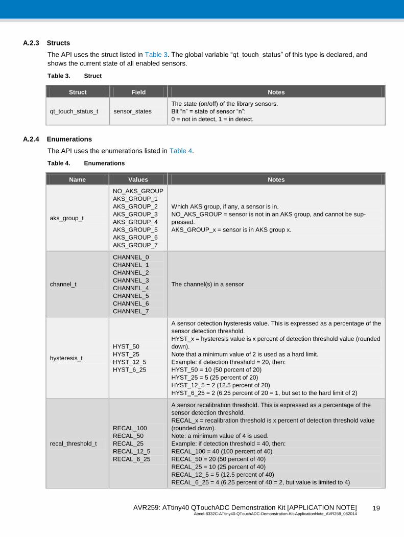
A.2.3 Structs
The API uses the struct listed in Table 3. The global variable “qt_touch_status” of this type is declared, and
shows the current state of all enabled sensors.
Table 3. Struct
Struct Field Notes
qt_touch_status_t sensor_states
The state (on/off) of the library sensors.
Bit “n” = state of sensor “n”:
0 = not in detect, 1 = in detect.
A.2.4 Enumerations
The API uses the enumerations listed in Table 4.
Table 4. Enumerations
Name Values Notes
aks_group_t
NO_AKS_GROUP
AKS_GROUP_1
AKS_GROUP_2
AKS_GROUP_3
AKS_GROUP_4
AKS_GROUP_5
AKS_GROUP_6
AKS_GROUP_7
Which AKS group, if any, a sensor is in.
NO_AKS_GROUP = sensor is not in an AKS group, and cannot be sup-
pressed.
AKS_GROUP_x = sensor is in AKS group x.
channel_t
CHANNEL_0
CHANNEL_1
CHANNEL_2
CHANNEL_3
CHANNEL_4
CHANNEL_5
CHANNEL_6
CHANNEL_7
The channel(s) in a sensor
hysteresis_t
HYST_50
HYST_25
HYST_12_5
HYST_6_25
A sensor detection hysteresis value. This is expressed as a percentage of the
sensor detection threshold.
HYST_x = hysteresis value is x percent of detection threshold value (rounded
down).
Note that a minimum value of 2 is used as a hard limit.
Example: if detection threshold = 20, then:
HYST_50 = 10 (50 percent of 20)
HYST_25 = 5 (25 percent of 20)
HYST_12_5 = 2 (12.5 percent of 20)
HYST_6_25 = 2 (6.25 percent of 20 = 1, but set to the hard limit of 2)
recal_threshold_t
RECAL_100
RECAL_50
RECAL_25
RECAL_12_5
RECAL_6_25
A sensor recalibration threshold. This is expressed as a percentage of the
sensor detection threshold.
RECAL_x = recalibration threshold is x percent of detection threshold value
(rounded down).
Note: a minimum value of 4 is used.
Example: if detection threshold = 40, then:
RECAL_100 = 40 (100 percent of 40)
RECAL_50 = 20 (50 percent of 40)
RECAL_25 = 10 (25 percent of 40)
RECAL_12_5 = 5 (12.5 percent of 40)
RECAL_6_25 = 4 (6.25 percent of 40 = 2, but value is limited to 4)
AVR259: ATtiny40 QTouchADC Demonstration Kit [APPLICATION NOTE] Atmel-8332C-ATtiny40-QTouchADC-Demonstration-Kit-ApplicationNote_AVR259_082014 2
0
20
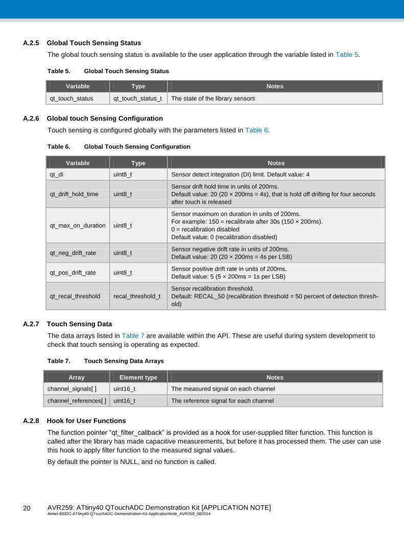
A.2.5 Global Touch Sensing Status
The global touch sensing status is available to the user application through the variable listed in Table 5.
Table 5. Global Touch Sensing Status
Variable Type Notes
qt_touch_status qt_touch_status_t The state of the library sensors
A.2.6 Global touch Sensing Configuration
Touch sensing is configured globally with the parameters listed in Table 6.
Table 6. Global Touch Sensing Configuration
Variable Type Notes
qt_di uint8_t Sensor detect integration (DI) limit. Default value: 4
qt_drift_hold_time uint8_t
Sensor drift hold time in units of 200ms.
Default value: 20 (20 × 200ms = 4s), that is hold off drifting for four seconds
after touch is released
qt_max_on_duration uint8_t
Sensor maximum on duration in units of 200ms.
For example: 150 = recalibrate after 30s (150 × 200ms).
0 = recalibration disabled
Default value: 0 (recalibration disabled)
qt_neg_drift_rate uint8_t Sensor negative drift rate in units of 200ms.
Default value: 20 (20 × 200ms = 4s per LSB)
qt_pos_drift_rate uint8_t Sensor positive drift rate in units of 200ms.
Default value: 5 (5 × 200ms = 1s per LSB)
qt_recal_threshold recal_threshold_t
Sensor recalibration threshold.
Default: RECAL_50 (recalibration threshold = 50 percent of detection thresh-
old)
A.2.7 Touch Sensing Data
The data arrays listed in Table 7 are available within the API. These are useful during system development to
check that touch sensing is operating as expected.
Table 7. Touch Sensing Data Arrays
Array Element type Notes
channel_signals[ ] uint16_t The measured signal on each channel
channel_references[ ] uint16_t The reference signal for each channel
A.2.8 Hook for User Functions
The function pointer “qt_filter_callback” is provided as a hook for user-supplied filter function. This function is
called after the library has made capacitive measurements, but before it has processed them. The user can use
this hook to apply filter function to the measured signal values.
By default the pointer is NULL, and no function is called.
AVR259: ATtiny40 QTouchADC Demonstration Kit [APPLICATION NOTE] Atmel-8332C-ATtiny40-QTouchADC-Demonstration-Kit-ApplicationNote_AVR259_082014
21
21
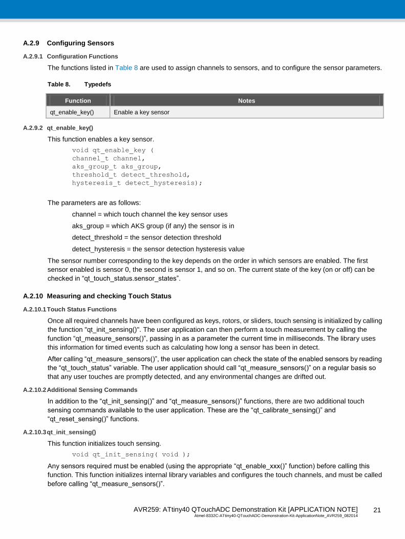
A.2.9 Configuring Sensors
A.2.9.1 Configuration Functions
The functions listed in Table 8 are used to assign channels to sensors, and to configure the sensor parameters.
Table 8. Typedefs
Function Notes
qt_enable_key() Enable a key sensor
A.2.9.2 qt_enable_key()
This function enables a key sensor.
void qt_enable_key (
channel_t channel,
aks_group_t aks_group,
threshold_t detect_threshold,
hysteresis_t detect_hysteresis);
The parameters are as follows:
channel = which touch channel the key sensor uses
aks_group = which AKS group (if any) the sensor is in
detect_threshold = the sensor detection threshold
detect_hysteresis = the sensor detection hysteresis value
The sensor number corresponding to the key depends on the order in which sensors are enabled. The first
sensor enabled is sensor 0, the second is sensor 1, and so on. The current state of the key (on or off) can be
checked in “qt_touch_status.sensor_states”.
A.2.10 Measuring and checking Touch Status
A.2.10.1 Touch Status Functions
Once all required channels have been configured as keys, rotors, or sliders, touch sensing is initialized by calling
the function "qt_init_sensing()". The user application can then perform a touch measurement by calling the
function “qt_measure_sensors()”, passing in as a parameter the current time in milliseconds. The library uses
this information for timed events such as calculating how long a sensor has been in detect.
After calling “qt_measure_sensors()”, the user application can check the state of the enabled sensors by reading
the “qt_touch_status” variable. The user application should call “qt_measure_sensors()” on a regular basis so
that any user touches are promptly detected, and any environmental changes are drifted out.
A.2.10.2 Additional Sensing Commands
In addition to the “qt_init_sensing()” and “qt_measure_sensors()” functions, there are two additional touch
sensing commands available to the user application. These are the “qt_calibrate_sensing()” and
“qt_reset_sensing()” functions.
A.2.10.3 qt_init_sensing()
This function initializes touch sensing.
void qt_init_sensing( void );
Any sensors required must be enabled (using the appropriate “qt_enable_xxx()” function) before calling this
function. This function initializes internal library variables and configures the touch channels, and must be called
before calling “qt_measure_sensors()”.

AVR259: ATtiny40 QTouchADC Demonstration Kit [APPLICATION NOTE] Atmel-8332C-ATtiny40-QTouchADC-Demonstration-Kit-ApplicationNote_AVR259_082014 2
2
22
A.2.10.4 qt_measure_sensors()
This function performs a capacitive measurement on all enabled sensors. The measured signals for each sensor
are then processed to check for user touches, releases, changes in rotor angle, changes in slider position, etc.
void qt_measure_sensors( uint16_t current_time_ms );
The parameter is as follows:
current_time_ms = the current time, in ms
The current state of all enabled sensors is reported in the “qt_touch_status” struct. Before calling this function,
one or more sensors must have been enabled (using the appropriate “qt_enable_xxx()” function), and
“qt_init_sensing()” must have been called.
A.2.10.5 qt_calibrate_sensing()
This function forces a recalibration of all enabled sensors. This may be useful if, for example, it is desired to
globally recalibrate all sensors on a change in application operating mode.
void qt_calibrate_sensing( void );
A.2.10.6 qt_reset_sensing()
This function disables all sensors and resets all library variables (for example, “qt_di”) to their default values. This
may be useful if it is desired to dynamically reconfigure sensing. After calling this function, any required sensors
must be re-enabled, and “qt_init_sensing()” must be called before “qt_measure_sensors()” is called again.
AVR259: ATtiny40 QTouchADC Demonstration Kit [APPLICATION NOTE] Atmel-8332C-ATtiny40-QTouchADC-Demonstration-Kit-ApplicationNote_AVR259_082014
23
23
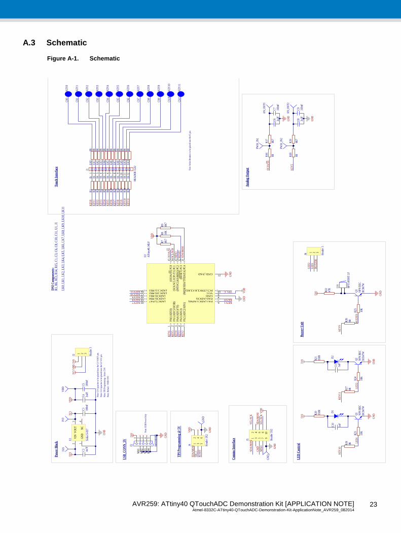
A.3 Schematic
Figure A-1. Schematic
2 1
D1
KE
Y5
CS5
1KR
6
2 1
D2
KE
Y6
CS6
KE
Y7
CS7
KE
Y8
CS8
1KR
101K
R11
1KR
12
: 100n
FC
5
150R
R20
150R
R21
5V0
VD
D
:
1nF
C11
:
1nF
C10
LE
D1
LE
D2
TP
I P
rogr
amm
ing
@ 5
V
Tou
ch I
nter
face
Com
ms
Inte
rfac
e
LE
D C
ontr
ol
Not
e: S
erie
s R
esis
tors
to b
e pl
aced
nea
r th
e IC
pin
.
Not
e: C
5 C
apac
itor
to b
e pl
aced
nea
r th
e U
2 V
CC
pin
.
BC
847W
Q2
NPN
BE
CB
C84
7W
Q1
NPN
BE
C10
K
R23
10K
R24
GN
DG
ND
5V0
10K
R8
VD
D
RE
SET
4K7
R7
4K7
R9
SCL
/SC
K
SDA
/MO
SI
2u2F
C4
4u7F
C2
GN
D
5V0
:
100n
FC
3
3V3
Pow
er B
lock
KE
Y4
CS4
KE
Y3
CS3
KE
Y9
CS9
KE
Y10
CS1
0
1KR
51K
R4
1KR
131K
R14
PA6
(AD
C6)
1
PA5
(AD
C5/
OC
0B)
2
PA3
(AD
C3)
4
PA0 (ADC0)7
GND8
VCC9
PC5 (TPICLK/CLKI)10
(MO
SI/S
DA
/TPI
DA
TA
) PC
411
(RE
SET
) PC
312
(IN
T0/
CL
KO
/MIS
O)
PC2
13(S
CK
/SC
L/I
CP1
/T1)
PC
114
PA2
(AD
C2/
AIN
1)5
PA1 (ADC1/AIN0)6
(ADC10) PB217
(ADC9) PB118
(ADC8) PB019
(ADC7) PA720
PA4
(AD
C4/
T0)
3
(OC
0A/S
S) P
C0
15
(ADC11) PB316
GND_PAD21
U2
AT
tiny4
0_M
LF
GN
D
1KR
31K
R2
1KR
15
KE
Y2
CS2
KE
Y1
CS1
KE
Y11
CS1
1
GN
D1
VO
UT
3
NC
4
VIN
2U
1
Seik
o S-
817
MIS
O
OC
0A/S
S
TPI_C
KE
Y0
KE
Y1
KE
Y2
KE
Y3
KE
Y4
KE
Y5
KE
Y6
KE
Y7
KE
Y8
KE
Y9
KE
Y10
KEY0KEY1
KE
Y2
KE
Y3
KE
Y4
KE
Y5
KE
Y6
KEY7KEY8KEY9KEY10
1 2 3
J2 Hea
der
3
VD
D5V
03V
3V
DD
Not
e: T
PI P
rogr
amm
ing
- Se
lect
5V
0
LS1
BPT
1403
H5
LF
Buz
zer
Uni
t
5V0
GN
D
BU
ZZ
ER
BC
847W
Q3
NPN
BE
C10
K
R25
47R
R22
GN
D
VD
D
12
34
56
J4 Hea
der
3X2
GN
D
TPI
_CSD
A/M
OSI
RE
SET
1 2 3
J6 Hea
der
3
BU
ZZ
ER
LE
D2
LE
D1
12
34
56
78
910
J5 Hea
der
5X2
GN
DV
DD
GN
D
SDA
/MO
SISC
L/S
CK
SDA
/MO
SISC
L/S
CK
MIS
O
2u2F
C6
: 330n
FC
7
2u2F
C8
: 330n
FC
94K
7
R19
4K7
R17
AN
_OU
T1
AN
_OU
T2
KE
Y5
OC
0A/S
S
GN
D
GN
D
Ana
log
Out
put
5V0
3V3
VD
D
GN
D
0RR18
0RR16
PWM
_IN
1
PWM
_IN
2
GN
D
MH
2M
H1
2 3 4 51
MH
3M
H4
J3 0481
9000
01
USB
_CO
NN
_5V
5V0
GN
D
0RR26
0RR27
0RR28
KE
Y11
KE
Y10
KE
Y9
DN
I C
ompo
nent
s:R
1, R
6, R
13, R
14, R
15, C
1, C
3, C
6, C
8, C
10, C
11, U
1, J
1
Not
e: C
3 C
apac
itor
to b
e pl
aced
nea
r th
e U
1 V
OU
T p
in.
Not
e: D
efau
lt : V
DD
=5V
0
Not
e: U
SB P
ower
Onl
y
2 7 83 4 9 101 5 11 126
J1
HE
AD
ER
1x1
2
KEY11
KE
Y0
CS0
1kR
1
KE
Y11
0RL
K1
0RL
K2
0RL
K3
0RL
K4
0RL
K5
0RL
K6
0RL
K7
0RL
K8
0RL
K9
0RL
K10
0RL
K11
0RL
K0
LK
0, L
K1,
LK
2, L
K3,
LK
4, L
K5,
LK
6, L
K7,
LK
8, L
K9,
LK
10, L
K11

AVR259: ATtiny40 QTouchADC Demonstration Kit [APPLICATION NOTE] Atmel-8332C-ATtiny40-QTouchADC-Demonstration-Kit-ApplicationNote_AVR259_082014 2
4
24
A.4 PCB
Figure A-2. PCB Top View

AVR259: ATtiny40 QTouchADC Demonstration Kit [APPLICATION NOTE] Atmel-8332C-ATtiny40-QTouchADC-Demonstration-Kit-ApplicationNote_AVR259_082014
25
25
A.5 BOM
Table 9. Install Components
SL NO Description Vendor Vendor part no. Designator Qty.
1 CAP CER 4µ7F 20% 0805 X5R 16V C2 1
2 CAP CER 2µ2F 20% 0805 X5R 16V C4 1
3 CAP CER 0µ1F 5% 0603 X7R 16V C5 1
4 CAP CER 330nF 5% 0603 X7R 16V C7, C9 2
5 CON HDR 3×1 3-pins 2.54mm J2 1
6 CON HDR 3×2 6-pins 2.54mm J4 1
7 CON HDR 5×2 10-pins 2.54mm J5 1
8 CON USB MINI B SMD Würth Elektronik 65100516121 J3 1
9 LED SMD RED 1206 Everlight 15-21SURC/S530-A2/TR8 D1, D2 2
10 BUZ 4kHz ±0.5 3.3Vp-p Bestar Acoustic BPT1403H5 LF LS1 1
11 BJT BC847B NPN SOT23 NXP BC847B Q1, Q2, Q3 3
12 RES SIN 0R 5% 0603 50V R16, R18, R26,
R27, R28 5
13 RES SIN 47R 5% 0603 50V R22 1
14 RES SIN 150R 5% 0603 50V R20, R21 2
15 RES SIN 1K 5% 0603 50V R2, R3, R4, R5,
R10, R11, R12 7
16 RES SIN 4K7 5% 0603 50V R7, R9, R17, R19 4
17 RES SIN 10K 5% 0603 50V R8, R23, R24, R25 4
18 IC ATtiny40 20-pin MLF Atmel ATtiny40-MMH U2 1
Table 10. Do not install Components
SL NO Description Vendor Vendor part no. Designator Qty.
1 CAP CER 2µ2F 20% 0805 X5R 16V C6, C8 2
2 CAP CER 0µ1F 5% 0603 X7R C3 1
3 CAP CER 1nF 5% 0603 X7R 16V C10, C11 2
4 RES SIN 0R 5% 0603 50V R1 1
5 RES SIN 1K 5% 0603 50V R6, R13, R14, R15 4
6 CON HDR 11-pins 2.54mm J1 1
7 IC CMOS VOLT REG Seiko S-817A33ANB-CUW-T2 U1 1
AVR259: ATtiny40 QTouchADC Demonstration Kit [APPLICATION NOTE] Atmel-8332C-ATtiny40-QTouchADC-Demonstration-Kit-ApplicationNote_AVR259_082014 2
6
26
A.6 References 1. ATtiny40 Datasheet
http://www.atmel.com/Images/Atmel-8263-8-bit-AVR-Microcontroller-tinyAVR-ATtiny40_Datasheet.pdf
2. Atmel QTouch Library http://www.atmel.com/tools/QTOUCHLIBRARY.aspx
3. BSW Sensor Design Guide http://www.atmel.com/Images/doc10752.pdf
4. Atmel AVR042: AVR Hardware Design Considerations http://www.atmel.com/images/atmel-2521-avr-hardware-design-considerations_application-note_avr042.pdf
5. AVR130: Setup and Use the AVR Timers http://www.atmel.com/Images/doc2505.pdf
AVR259: ATtiny40 QTouchADC Demonstration Kit [APPLICATION NOTE] Atmel-8332C-ATtiny40-QTouchADC-Demonstration-Kit-ApplicationNote_AVR259_082014
27
27
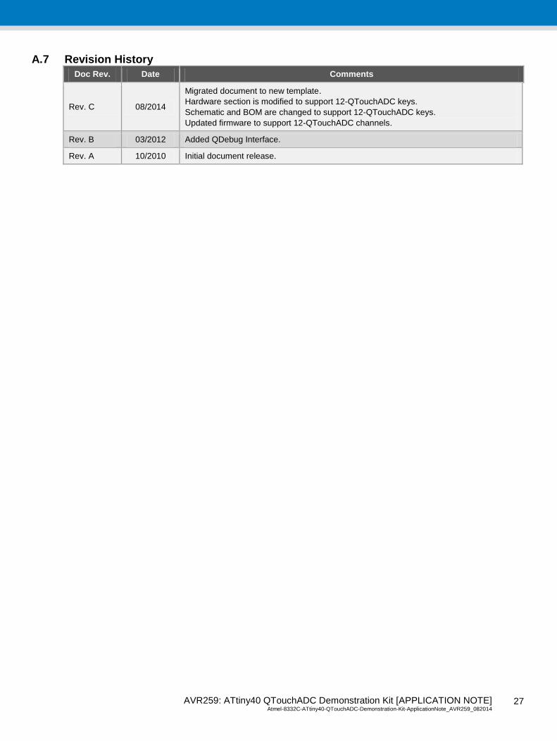
A.7 Revision History
Doc Rev. Date Comments
Rev. C 08/2014
Migrated document to new template.
Hardware section is modified to support 12-QTouchADC keys.
Schematic and BOM are changed to support 12-QTouchADC keys.
Updated firmware to support 12-QTouchADC channels.
Rev. B 03/2012 Added QDebug Interface.
Rev. A 10/2010 Initial document release.

AVR259: ATtiny40 QTouchADC Demonstration Kit [APPLICATION NOTE] Atmel-8332C-ATtiny40-QTouchADC-Demonstration-Kit-ApplicationNote_AVR259_082014 2
8
28
Atmel Corporation 1600 Technology Drive, San Jose, CA 95110 USA T: (+1)(408) 441.0311 F: (+1)(408) 436.4200 www.atmel.com
© 2014 Atmel Corporation. / Rev.:Atmel-8332C-ATtiny40-QTouchADC-Demonstration-Kit-ApplicationNote_AVR259_082014. Atmel
®, Atmel logo and combinations thereof, Adjacent Key Suppression
®, AKS
®, AVR
®, Enabling Unlimited Possibilities
®, QTouch
®, tinyAVR
®, and others are
registered trademarks or trademarks of Atmel Corporation in U.S. and other countries. Other terms and product names may be trademarks of others. DISCLAIMER: The information in this document is provided in connection with Atmel products. No license, express or implied, by estoppel or otherwise, to any intellectual property right
is granted by this document or in connection with the sale of Atmel products. EXCEPT AS SET FORTH IN THE ATMEL TERMS AND CONDITIONS OF SALES LOCATED ON THE ATMEL WEBSITE, ATMEL ASSUMES NO LIABILITY WHATSOEVER AND DISCLAIMS ANY EXPRESS, IMPLIED OR STATUTORY WARRANTY RELATING TO ITS PRODU CTS INCLUDING, BUT NOT LIMITED TO, THE IMPLIED WARRANTY OF MERCHANTABILITY, FITNESS FOR A PARTICULAR PURPOSE, OR NON -INFRINGEMENT. IN NO EVENT SHALL ATMEL BE
LIABLE FOR ANY DIRECT, INDIRECT, CONSEQUENTIAL, PUNITIVE, SPECIAL OR INCIDENTAL DAMAGES (INCLUDING, WITHOUT LIMITATION, DAMAG ES FOR LOSS AND PROFITS, BUSINESS INTERRUPTION, OR LOSS OF INFORMATION) ARISING OUT OF THE USE OR INABILITY TO USE THIS DOCUMENT, EVEN IF ATMEL HAS BEEN ADVISED OF THE POSSIBILITY OF SUCH DAMAGES. Atmel makes no representations or warranties with respect to the accuracy or completeness of the contents of this document and reserves
the right to make changes to specifications and products descriptions at any time without notice. Atmel does not make any commitment to update the information contained herein. Unless specifically provided otherwise, Atmel products are not suitable for, and shall not be used in, automotive applications. Atmel products are not intended, authorized, or warranted for use as components in applications intended to support or sustain life.
SAFETY-CRITICAL, MILITARY, AND AUTOMOTIVE APPLICATIONS DISCLAIMER: Atmel products are not designed for and will not be used in connection with any applications where
the failure of such products would reasonably be expected to result in significant personal injury or death (“Safety -Critical Applications”) without an Atmel officer's specific wri tten consent. Safety-Critical Applications include, without limitation, life support devices and systems, equipment or systems for the operation o f nuclear facilities and weapons systems. Atmel products are not designed nor intended for use in military or aerospace applications or environments unless specifically designated by Atmel as military-grade. Atmel products are not designed nor
intended for use in automotive applications unless specifically designated by Atmel as automotive -grade.


![Atmel QTouch Library PTC Release Note · Atmel PTC QTouch Library [RELEASE NOTES] Atmel-42544-PTC-QTouch-Library_ReleaseNotes 10 Fixed code generation logic for low power mega PTC](https://static.fdocuments.in/doc/165x107/60d59fbe8ad0960085088288/atmel-qtouch-library-ptc-release-note-atmel-ptc-qtouch-library-release-notes-atmel-42544-ptc-qtouch-libraryreleasenotes.jpg)


![Atmel SAM C20 QTouch Safety Library User Guide...Atmel SAM C20 Safety Library [USER GUIDE] Atmel-42679C-SAM-C20-QTouch-Safety-Library_User Guide-07/2016 9 Figure 2-4. API Usage Yes](https://static.fdocuments.in/doc/165x107/60b1328d4317f551c152eff4/atmel-sam-c20-qtouch-safety-library-user-guide-atmel-sam-c20-safety-library.jpg)


![ATA6286-EK3 Active RFID Evaluation Kitww1.microchip.com/downloads/en/AppNotes/Atmel-9289-ATA6286-EK3... · ATA6286-EK3 Active RFID Evaluation Kit ATAN0057. ATAN0057 [APPLICATION NOTE]](https://static.fdocuments.in/doc/165x107/5aa4ac107f8b9a185d8c595c/ata6286-ek3-active-rfid-evaluation-active-rfid-evaluation-kit-atan0057-atan0057.jpg)


![Atmel AVR3004: QTouch with Safety Featuresww1.microchip.com/downloads/en/AppNotes/doc42041.pdfAtmel AVR3004: QTouch with Safety Features [APPLICATION NOTE] 42041A−AVR−11/2012 7](https://static.fdocuments.in/doc/165x107/607a280de973d0259f4a47f5/atmel-avr3004-qtouch-with-safety-atmel-avr3004-qtouch-with-safety-features-application.jpg)