
AVR247om lores
76
AVR 247 AUDIO/VIDEO RECEIVER OWNER’S MANUAL
-
Upload
jimmy-mack -
Category
Documents
-
view
227 -
download
0
Transcript of AVR247om lores

8/2/2019 AVR247om lores
http://slidepdf.com/reader/full/avr247om-lores 1/76
AVR 247 AUDIO/VIDEO RECEIVER
OWNER’S MANUAL
8/2/2019 AVR247om lores
http://slidepdf.com/reader/full/avr247om-lores 2/76
2
SAFETY INFORMATION
1. Read Instructions. All the safety and operating instruc-
tions should be read before the product is operated.
2. Retain Instructions. The safety and operating instruc-
tions should be retained for future reference.
3. Heed Warnings. All warnings on the product and in the
operating instructions should be adhered to.
4. Follow Instructions. All operating and use instructions
should be followed.
5. Cleaning. Unplug this product from the wall outlet before
cleaning. Do not use liquid cleaners or aerosol cleaners. Use
a damp cloth for cleaning.
6. Attachments. Do not use attachments not recommended
by the product manufacturer, as they may cause hazards.
7. Water and Moisture. Do not use this product near
water – for example, near a bathtub, wash bowl, kitchen
sink or laundry tub; in a wet basement; near a swimming
pool; or the like.
8. Accessories. Do not place this product on an unstablecart, stand, tripod, bracket or table.The product may fall,
causing serious injury to a child or adult, and serious dam-
age to the product. Use only with a cart, stand, tripod,
bracket or table recommended by the manufacturer, or sold
with the product. Any mounting of the product should follow
the manufacturer’s instructions, and should use a mounting
accessory recommended by the manufacturer.
9. A Product and Cart Combination Should
Be Moved With Care. Quick stops, excessive
force and uneven surfaces may cause the
product and cart combination to overturn.
10. Ventilation. Slots and openings in the cabinet are pro-
vided for ventilation and to ensure reliable operation of theproduct and to protect it from overheating, and these open-
ings must not be blocked or covered. The openings should
never be blocked by placing the product on a bed, sofa, rug
or other similar surface.This product should not be placed in
a built-in installation, such as a bookcase or rack, unless
proper ventilation is provided or the manufacturer’s instruc-
tions have been adhered to.
11. Power Sources. This product should be operated only
from the type of power source indicated on the marking
label. If you are not sure of the type of power supply to your
home, consult your product dealer or local power company.
For products intended to operate from battery power, or
other sources, refer to the operating instructions.
12. Polarization. This product may be equipped with a
polarized alternating-current-line plug (a plug having one
blade wider than the other). This plug will fit into the power
outlet only one way. This is a safety feature. If you are unable
to insert the plug fully into the outlet, try reversing the plug.
If the plug should still fail to fit, contact your electrician to
replace your obsolete outlet. Do not defeat the safety pur-
pose of the polarized plug.
13. Power-Cord Protection. Power-supply cords should be
routed so that they are not likely to be walked on or pinched
by items placed upon or against them, paying particular
attention to cords at plugs, convenience receptacles, and
the point where they exit from the product.
14. Nonuse Periods. The power cord of the product should
be unplugged from the outlet when left unused for long
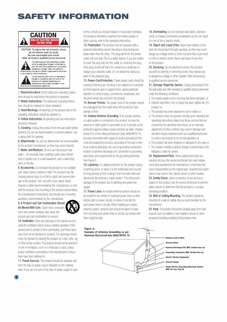
periods of time.15. Outdoor Antenna Grounding. If an outside antenna
or cable system is connected to the product, be sure the
antenna or cable system is grounded so as to provide some
protection against voltage surges and built-up static charges.
Article 810 of the National Electrical Code, ANSI/NFPA 70,
provides information with regard to proper grounding of the
mast and supporting structure, grounding of the lead-in wire
to an antenna discharge unit, size of grounding conductors,
location of antenna-discharge unit, connection to grounding
electrodes, and requirements for the grounding electrode.
See Figure A.
16. Lightning. For added protection for this product during
a lightning storm, or when it is left unattended and unusedfor long periods of time, unplug it from the wall outlet and
disconnect the antenna or cable system. This will prevent
damage to the product due to lightning and power-line
surges.
17. Power Lines. An outside antenna system should not
be located in the vicinity of overhead power lines or other
electric light or power circuits, or where it can fall into
such power lines or circuits. When installing an outside
antenna system, extreme care should be taken to keep
from touching such power lines or circuits, as contact with
them might be fatal.
18. Overloading. Do not overload wall outlets, extension
cords, or integral convenience receptacles, as this can result
in a risk of fire or electric shock.
19. Object and Liquid Entry. Never push objects of any
kind into this product through openings, as they may touch
dangerous voltage points or short-out parts that could result
in a fire or electric shock. Never spill liquid of any kind
on the product.
20. Servicing. Do not attempt to service this product
yourself, as opening or removing covers may expose you
to dangerous voltage or other hazards. Refer all servicing
to qualified service personnel.
21. Damage Requiring Service. Unplug this product from
the wall outlet and refer servicing to qualified service personnel
under the following conditions:
a. The power-supply cord or the plug has been damaged; or
b. Objects have fallen onto, or liquid has been spilled into, the
product; or
c. The product has been exposed to rain or water; ord. The product does not operate normally when following the
operating instructions. Adjust only those controls that are
covered by the operating instructions, as an improper
adjustment of other controls may result in damage and
will often require extensive work by a qualified technician
to restore the product to its normal operation; or
e. The product has been dropped or damaged in any way; or
f. The product exhibits a distinct change in performance; this
indicates a need for service.
22. Replacement Parts. When replacement parts are
required, be sure the service technician has used replace-
ment parts specified by the manufacturer or that have the
same characteristics as the original part. Unauthorized substi-tutions may result in fire, electric shock or other hazards.
23. Safety Check. Upon completion of any service or
repairs to this product, ask the service technician to perform
safety checks to determine that the product is in proper
operating condition.
24. Wall or Ceiling Mounting. The product should be
mounted to a wall or ceiling only as recommended by the
manufacturer.
25. Heat. The product should be situated away from heat
sources such as radiators, heat registers, stoves or other
products (including amplifiers) that produce heat.
Antenna Lead-In Wire
Ground Clamp
Antenna Discharge Unit (NEC Section 810-20)
Grounding Conductors (NEC Section 810-21)
Electric Service Equipment
Ground Clamps
Power Service Grounding Electrode System(NEC Art 250, Part H)
Figure A.Example of Antenna Grounding as per
National ElectricalCode ANSI/NFPA 70
8/2/2019 AVR247om lores
http://slidepdf.com/reader/full/avr247om-lores 3/76
3
Important Safety Information
Verify Line Voltage Before Use
Your AVR 247 has been designed for use with 120-volt AC current. Connection to
a line voltage other than that for which it is intended can create a safety and fire
hazard and may damage the unit.
If you have any questions about the voltage requirements for your specific model, orabout the line voltage in your area, contact your selling dealer before plugging the unit
into a wall outlet.
Do Not Use Extension Cords
To avoid safety hazards, use only the power cord attached to your unit. We do not
recommend that extension cords be used with this product. As with all electrical
devices, do not run power cords under rugs or carpets or place heavy objects on
them. Damaged power cords should be replaced immediately by an authorized service
center with a cord meeting factory specifications.
Handle the AC Power Cord Gently
When disconnecting the power cord from an AC outlet, always pull the plug; never
pull the cord. If you do not intend to use the unit for any considerable length of time,
disconnect the plug from the AC outlet.
Do Not Open the Cabinet
There are no user-serviceable components inside this product. Opening the cabinet
may present a shock hazard, and any modification to the product will void your
guarantee. If water or any metal object such as a paper clip, wire or staple acciden-
tally falls inside the unit, disconnect it from the AC power source immediately, and
consult an authorized service center.
CATV or Antenna Grounding
If an outside antenna or cable system is connected to this product, be certain that it is
grounded so as to provide some protection against voltage surges and static charges.
Section 810 of the National Electrical Code, ANSI/NFPA No. 70-1984, provides
information with respect to proper grounding of the mast and supporting structure,
grounding of the lead-in wire to an antenna discharge unit, size of grounding conduc-tors, location of antenna discharge unit, connection to grounding electrodes and
requirements of the grounding electrode.
NOTE TO CATV SYSTEM INSTALLER: This reminder is provided to call the CATV
(cable TV) system installer’s attention to article 820-40 of the NEC, which provides
guidelines for proper grounding and, in particular, specifies that the cable ground
shall be connected to the grounding system of the building, as close to the point
of cable entry as possible.
Installation Location
• To ensure proper operation and to avoid the potential for safety hazards, place the
unit on a firm and level surface.When placing the unit on a shelf, be certain that
the shelf and any mounting hardware can support the weight of the product.
• Make certain that proper space is provided both above and below the unit for
ventilation. If this product will be installed in a cabinet or other enclosed area,make certain that there is sufficient air movement within the cabinet. Under some
circumstances, a fan may be required.
• Do not place the unit directly on a carpeted surface.
• Avoid installation in extremely hot or cold locations, or in an area that is exposed
to direct sunlight or heating equipment.
• Avoid moist or humid locations.
• Do not obstruct the ventilation slots on the top of the unit, or place objects
directly over them.
• Due to the weight of the AVR 247 and the heat generated by the amplifiers,
there is the remote possibility that the rubber padding on the bottom of the
unit’s feet may leave marks on certain wood or veneer materials. Use caution
when placing the unit on soft woods or other materials that may be damaged
by heat or heavy objec ts. Some surface finishes may be particularly sensitive to
absorbing such marks, due to a variety of factors beyond Harman Kardon's con-
trol, including the nature of the finish, cleaning materials used, and normal heat
and vibration caused by the use of the product, or other factors. We recommend
that caution be exercised in choosing an installation location for the component andin normal maintenance practices, as your warranty will not cover this type of damage
to furniture.
Cleaning
When the unit gets dirty, wipe it with a clean, soft, dry cloth. If necessary, and only after
unplugging the AC power cord, wipe it with a soft cloth dampened with mild soapy
water, then a fresh cloth with clean water. Wipe it dry immediately with a dry cloth.
NEVER use benzene, aerosol cleaners, thinner, alcohol or any other volatile cleaning
agent. Do not use abrasive cleaners, as they may damage the finish of metal parts.
Avoid spraying insecticide near the unit.
Moving the Unit
Before moving the unit, be certain to disconnect any interconnection cords
with other components, and make certain that you disconnect the unit fromthe AC outlet.
Important Information for the User
This equipment has been tested and found to comply with the limits for a Class-B
digital device, pursuant to Part 15 of the FCC Rules. The limits are designed to pro-
vide reasonable protection against harmful interference in a residential installation.
This equipment generates, uses and can radiate radio-frequency energy and, if not
installed and used in accordance with the instructions, may cause harmful interfer-
ence to radio communication. However, there is no guarantee that harmful interfer-
ence will not occur in a particular installation. If this equipment does cause harmful
interference to radio or television reception, which can be determined by turning the
equipment off and on, the user is encouraged to try to correct the interference by
one or more of the following measures:
• Reorient or relocate the receiving antenna.• Increase the separation between the equipment and receiver.
• Connect the equipment into an outlet on a circuit different from that to which the
receiver is connected.
• Consult the dealer or an experienced radio/TV technician for help.
This device complies with Part 15 of the FCC Rules. Operation is subject to the
following two conditions: (1) this device may not cause harmful interference, and
(2) this device must accept interference received, including interference that may
cause undesired operation.
NOTE: Changes or modifications may cause this unit to fail to comply with Part 15 of
the FCC Rules and may void the user’s authority to operate the equipment.
Unpacking
The carton and shipping materials used to protect your new receiver during ship-ment were specially designed to cushion it from shock and vibration. We suggest
that you save the carton and packing materials for use in shipping if you move, or
should the unit ever need repair.
To minimize the size of the carton in storage, you may wish to flatten it. This is done
by carefully slitting the tape seams on the bottom and collapsing the carton. Other card-
board inserts may be stored in the same manner. Packing materials that cannot be col-
lapsed should be saved along with the carton in a plastic bag.
If you do not wish to save the packaging materials, please note that the carton and
other sections of the shipping protection are recyclable. Please respect the environ-
ment and discard those materials at a local recycling center.
It is important that you remove the protective plastic film from the front-panel lens.
Leaving the film in place will affect the performance of your remote control.
SAFETY INFORMATION

8/2/2019 AVR247om lores
http://slidepdf.com/reader/full/avr247om-lores 4/76
4
STAPLE INVOICE HERE

8/2/2019 AVR247om lores
http://slidepdf.com/reader/full/avr247om-lores 5/76
5
2 SAFETY INFORMATION
6 INTRODUCTION
8 FRONT-PANEL CONTROLS
10 REAR-PANEL CONNECTIONS
13 REMOTE CONTROL FUNCTIONS
16 INTRODUCTION TO HOME THEATER
17CONNECTIONS
17 Speaker Connections
17 Subwoofer
17 Connecting Source Devices to the AVR
18 Audio Connections
18 Digital Audio
19 Analog Audio
19 Video Connections
19 Digital Video
19 Analog Video
20 Antennas
20 RS-232 Serial Port
21 SPEAKER PLACEMENT
23 INSTALLATION
23 Step One – Connect the Speakers
23 Step Two – Connect the Subwoofer23 Step Three – Connect the Antennas
23 Step Four – Connect the Source Components
27 Step Five – Connect the Video Display
27 Step Six – Plug in AC Power
28 Step Seven – Insert Bat teries in Remote
28 Step Eight – Program Sources Into the Remote
29 Step Nine – Remote IR Inputs and Output
29 Step Ten – Install a Mul ti room System
30 Step Eleven – Turn On the AVR 247
31 INITIAL SETUP
31 Using the On-Screen Menu System
32 Configure the AVR 247 Using EzSet/EQ
33 What EzSet/EQ Does
34 Configure Sources
37 OPERATION
37 Turning On the AVR 247
37 Sleep Timer
37 Volume Control
37 Mute Function
38 Tone Controls
38 Headphones
38 Source Selection
39 Audio Input Selection
39 Video Input Selection
39 6-/8-Channel Direct Inputs
40 Using the Tuner
41 XM Radio Operation
42 Recording
42 Using44 Selecting a Surround Mode
45 ADVANCED FUNCTIONS
45 Audio Processing and Surround Sound
45 Analog Audio Signals
45 Digital Audio Signals
46 Surround Modes
47 Dolby Surround Settings
47 Default Modes51 Manual Setup
51 Step One – Determine Speaker Size
51 Step Two – Measure Speaker Distances
51 Step Three – Manual Setup Menu
52 Speaker Size Menu
53 Speaker Crossover Menu
53 Delay Adjust Menu
54 Step Four – Setting Channel Output Levels Manually
55 Video Adjustments
56 Multiroom Operation
56 Installing a Multiroom System
57 Operating the Multiroom System
57 System Settings
58 Dim Function
58 Advanced Remote Control Functions58 Punch-Through Programming
59 Macros
59 Resetting the Remote
59 Processor Reset
59 Memory
60 TROUBLESHOOTING GUIDE
61 TECHNICAL SPECIFICATIONS
61, 64 Trademark Acknowledgements
62 APPENDIX
The
BridgeTM
WARNING
For Canadian model
Modèle pour les Canadien
Cet appareil numérique de la classe B est conformeà la norme NMB-003 du Canada.
Sur les modèles dont la fiche est polarisee:
ATTENTION: Pour éviter les chocs électriques, introduire
la lame la plus large de la fiche dans la borne
correspondante de la prise et pousser jusqu’au fond.
This class B digital apparatus complies with Canadian
ICES-003.
For models having a power cord with a polarized plug:
CAUTION: To prevent electric shock, match wide blade
of plug to wide slot, fully insert.
To prevent fire or shock hazard, do not expose this
appliance to rain or moisture.
TABLE OF CONTENTS
8/2/2019 AVR247om lores
http://slidepdf.com/reader/full/avr247om-lores 6/76
6
Thank you for choosing Harman Kardon®!
In the years since Harman Kardon invented the high-fidelity receiver,we have taken to heart the philosophy of bringing the joy of homeentertainment to as many people as possible, adding performance and
ease-of-use features that enhance the home entertainment experience.In the years since our first single-channel component was introduced,
Harman Kardon has offered a number of receiver models, each animprovement upon its predecessors, leading to the AVR 247, a
7.1-channel digital audio/video receiver that offers a wealth of listeningand viewing options, all in an elegant package.
To obtain the maximum enjoyment from your new receiver, we urge youto read this manual and refer back to it as you become more familiar
with its features and their operation.
If you have any questions about this product, its installation or itsoperation, please contact your retailer or customer installer, or visit our
Web site at www.harmankardon.com.
Please register your AVR 247 on our Web site at www.harmankardon.com.
Note: You’ll need the product’s serial number. At the same time, you can choose to be notified about our new products
and/or special promotions.
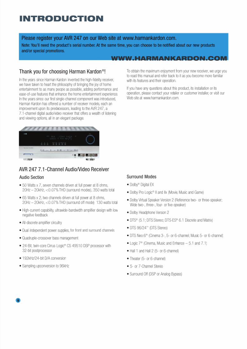
AVR 247 7.1-Channel Audio/Video Receiver
Audio Section
• 50 Watts x 7, seven channels driven at full power at 8 ohms,20Hz – 20kHz, <0.07% THD (surround modes), 350 watts total
• 65 Watts x 2, two channels driven at full power at 8 ohms,20Hz – 20kHz, <0.07% THD (surround off mode), 130 watts total
• High-current capability, ultrawide-bandwidth amplifier design with lownegative feedback
• All-discrete amplifier circuitry
• Dual independent power supplies, for front and surround channels
• Quadruple-crossover bass management
• 24-Bit, twin-core Cirrus Logic® CS 49510 DSP processor with32-bit postprocessor
• 192kHz/24-bit D/A conversion
• Sampling upconversion to 96kHz
Surround Modes
• Dolby® Digital EX
• Dolby Pro Logic® II and IIx (Movie, Music and Game)
• Dolby Virtual Speaker Version 2 (Reference two- or three-speaker;
Wide two-, three-, four- or five-speaker)
• Dolby Headphone Version 2
• DTS® (5.1; DTS Stereo; DTS-ES® 6.1 Discrete and Matrix)
• DTS 96/24™ (DTS Stereo)
• DTS Neo:6® (Cinema 3-, 5- or 6-channel; Music 5- or 6-channel)
• Logic 7®
(Cinema, Music and Enhance – 5.1 and 7.1)• Hall 1 and Hall 2 (5- or 6-channel)
• Theater (5- or 6-channel)
• 5- or 7-Channel Stereo
• Surround Off (DSP or Analog Bypass)
WWW.HARMANKARDON.COM
INTRODUCTION
8/2/2019 AVR247om lores
http://slidepdf.com/reader/full/avr247om-lores 7/76
7
INTRODUCTION
Audio Inputs
• AM/FM/XM®* tuner
• CD
• Tape
• 6-/8-Channel direct
• /DMP for iPod** connectivity with audio/video playback
Audio/Video Inputs (With S-Video)
• Video 1
• Video 2
• Video 3
• Video 4 (on front panel)
• DVD
• Three assignable 100MHz component video inputs
• Simplay HD™-verified HDMI™ 1 and 2 (with audio/video processing
and 1080p pass-through)
• DCDi® by Faroudja video processing
Transcodes composite and S-video to component video
Transcodes 480i video to HDMI format, with upscaling up to 720p
Upgraded graphic text-based on-screen displays
Digital Audio Inputs• Coaxial: two rear-panel/one front-panel
• Optical: two rear-panel/one front-panel
Outputs
• 7.1-Channel preamp outputs
• Tape (analog audio)
• Video 1 (analog audio and video)
• Video monitor (composite, S-video and component)
• Digital audio (one coaxial, one optical)
• Simplay HD-verified HDMI
• Multiroom audio: speaker- and line-level (shared with surroundback channels)
• Headphone
Ease of Use
• EzSet/EQ™ automated setup (microphone supplied)
• Graphic on-screen display with HDMI, component, composite
and S-video
• Two-line dot-matrix front-panel display
• Color-coded connections
• Programmable 11-device main remote control
• Source input renaming
• A/V Sync Delay
• RS-232 serial port for system upgrades
• Switched accessory power outlet
• Remote infrared (IR) input and output
• Multiroom IR input
The AVR 247 is Simplay HD-verified for compatibility
via the HDMI connection with other Simplay HD-verified products.
Supplied Accessories
The following accessory items are supplied with the AVR 247. If any
of these items are missing, please contact Harman Kardon customerservice at www.harmankardon.com.
• System remote control
• EzSet/EQ microphone
• AM loop antenna
• FM wire antenna
• Three AAA batteries
• Two covers for front-panel jacks
TheBridgeTM
*XM antenna module and subscription to XM service required. Hardware and
service sold separately. XM service is not available in Alaska or Hawaii.
**Compatible with all iPod models equipped with a dock connector. Not compatible
with iPod shuffle models. Images and videos stored on iPod photo and video
models may be viewed.

8/2/2019 AVR247om lores
http://slidepdf.com/reader/full/avr247om-lores 8/76
8
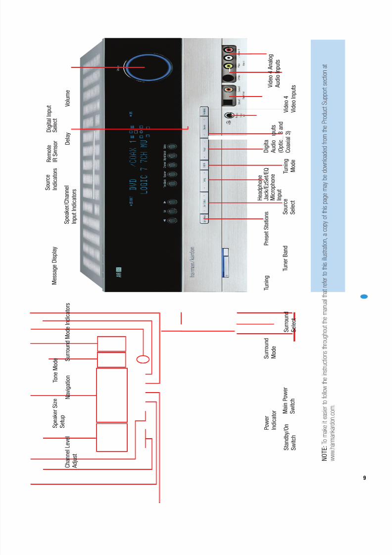
Main Power Switch: This mechanical switch turns the power supplyon or off. It is usually left pressed in (On position), and cannot be turned
on using the remote control.
Standby/On Switch: This electrical switch turns the receiver on
for playback, or leaves it in Standby mode for quick turn-on using this
switch or the remote control.
Power Indicator: This LED has three possible modes. When mainpower is turned off, the LED is dark and the receiver won’t respond toany button presses. When main power is turned on, but before the
Standby/On Switch is used, the LED turns amber to indicate that thereceiver is in Standby mode and ready to be turned on. When the
receiver is turned on, the LED turns blue.
Source Select: Press this button to select a source device, which
is a component where a playback signal originates, e.g., DVD, CD,cable TV, satellite or HDTV tuner.
Source Indicators: The name of the current source input lights up.
The indicated input changes each time the Source Select button ispressed.
Volume Knob: Turn this knob to raise or lower the volume, which willbe shown in decibels (dB) in the Message Display.
Message Display: Various messages appear in this two-line displayin response to commands and changes in the incoming signal. When
the on-screen display menu system (OSD) is in use, the message OSDON will appear to remind you to check the video display.
Tuner Band: Press this button to select the tuner as the source, toswitch between the AM and FM bands, or to select XM satellite radio.
Tuning: Press either side of this button to tune a radio station orXM channel.
Tuning Mode: This button toggles between manual (one frequency
step at a time) and automatic (seeks frequencies with acceptable signalstrength) tuning mode. It also toggles between stereo and mono modes
when an FM station is tuned.
When XM Radio is in use, pressing this button repeatedly displays the
channel name, category, artist and track title in the lower line of theMessage Display. For traffic-and-weather channels, this button displaysthe city, channel name, local weather and local temperature.
Preset Stations: Press this button to select a preset radio station.
Headphone Jack/EzSet/EQ Microphone Input: Plug a 1/4"
headphone plug into this jack for private listening.
This jack is also used to connect the supplied microphone before begin-
ning the EzSet/EQ procedure described in the Initial Setup section. Tobegin EzSet/EQ, plug the supplied microphone into this jack, place the
microphone at the listening position, and follow the directions given inthe Speaker Setup-Auto Configuration on-screen menu.
Surround Mode: Press this button to select a surround sound (e.g.,multichannel) mode group. Choose from the Dolby modes, DTS modes,
Logic 7 modes, DSP modes or Stereo modes.
Surround Select: After you have selected the desired surround
mode group, press this button to select a specific mode.
Surround Mode Indicators: One or more of these icons may light
up as you select different surround modes. The Message Display alsoindicates the surround mode.
Analog Audio, Video and Digital Audio Inputs: Connect a
source component that will only be used temporarily, such as a cameraor game console, to these jacks. Use only one type of audio and one
type of video connection.
Speaker/Channel Input Indicators: The box icons indicate
which speaker positions you have configured, and the size (frequencyrange) of each speaker. When a digital audio input is used, letters will
light inside the boxes to indicate which channels are present in the
incoming signal.
Navigation: These buttons are used together with the following five
buttons to make selections.
Tone Mode: Press this button to access the tone controls (bass and
treble). Use the ‹ / › Navigation Buttons to make your selections.
Speaker: Press this button to configure speaker sizes, that is, the
low-frequency-range capability of each speaker.
Channel Level Adjust: Press this button to set the output level for
each channel so that all speakers sound equally loud at the listeningposition.
Digital Input Select: Press this button to select the specific digital
audio input (or analog audio input) you used for the current source.
Delay: Press this button to set delay times that compensate for
placing the speakers at different distances from the listening position.
Remote IR Sensor: This sensor receives infrared (IR) commands
from the remote control. It is important to ensure that it is not blocked.If covering the sensor is unavoidable, such as when the AVR 247 is
placed inside a cabinet, you may use an optional Harman KardonHE 1000, or other infrared receiver, connecting it to the Remote IRInput on the AVR 247’s rear panel. Alternatively, connect the Remote IR
Output of another compatible component to the AVR 247’s Remote
IR Input. Point the remote at the other device’s remote sensor, and thecommand will be transmitted to the AVR 247. An external IR “blaster”may also be used, positioned to point at this area.
FRONT-PANEL CONTROLS
8/2/2019 AVR247om lores
http://slidepdf.com/reader/full/avr247om-lores 9/76
9
S u r r o u n d
M o d e
T u n i n g
P r e s e t S t a t i o n s
S u r r o u n d
S e l e c t
T u n e r B a n d
T u n i n g
M o d e
S o u r c e
S e l e c t H e a
d p h o n e
J a c
k / E z S e t / E Q
M i c
r o p h o n e
I n p u t
D i g i t a l
A u d i o I n p u t s
( O p t i c a l 3 a n d
C o a x i a l 3 )
V i d e o 4
V i d e o I n
p u t s V
i d e o 4 A n a l o g
A u d i o I n p u t s
N a v i g
a t i o n
T o n e M o d e
S p e a k e r S i z e
S e t u p
D e l a y
D i g i t a l I n p u t
S e l e c t
P o w e r
I n d i c a t o r M
a i n P o w e r
S w i t c h
S t a n d b y / O n
S w i t c h
V o l u m
e
S o u r c e
I n d i c a t o r s
M e s s a g e D i s p l a y
S u r r o u n d M o d e I n d i c a t o r s
S p e a k e r / C h a n
n e l
I n p u t I n d i c a t o r s
C h a n n e l L e v e l
A d j u s t
R e m o t e
I R S e n s o r
N O T E : T o m a k e i t e a s i e r t o f o l l o w
t h e i n s t r u c t i o n s t h r o u g h o u t t h e m a n u a l t h a
t r e f e r t o t h i s i l l u s t r a t i o n ,
a c o p y o f t h i s p a g e
m a y b e d o w n l o a d e d f r o m
t h e P r o d u c t S u p
p o r t s e c t i o n a t
w w w . h
a r m a n k a r d o n . c
o m .
8/2/2019 AVR247om lores
http://slidepdf.com/reader/full/avr247om-lores 10/76
10
REAR-PANEL CONNECTIONS
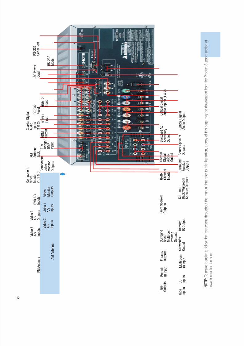
AM and FM Antenna Terminals: Connect the included AM andFM antennas to their respective terminals for radio reception.
XM Antenna Jack: Plug in an XM antenna module here. The XMantenna module is purchased separately, and should specify that it is
for home use with an XM Ready® product. You will need to subscribe to
the XM service, which is available separately, and activate the service foryour antenna module. (XM service is not available in Alaska and Hawaii.)
Front, Center and Surround Speaker Outputs: Use two-conductor speaker wire to connect each set of terminals to the correct
speaker. Remember to observe the correct polarity (positive and negativeconnections). Always connect the positive lead to the colored terminal
on the receiver and the red terminal on the speaker. Connect the negativelead to the black terminal on both the receiver and the speaker. See the
Connections section for more information on connecting your speakers.
Surround Back/Multiroom Speaker Outputs: These speakeroutputs may be used either for the surround back channels in a 7.l-
channel home theater, or they may be reassigned to a remote room foruse with a multiroom system.When these outputs are reassigned for
multiroom operation, only a 5.1-channel configuration will be available inthe main listening room. Use the on-screen menu system to configure
these channels as desired.
As with the other speaker outputs, remember to observe proper polarity
by connecting the positive and negative output terminals to the corre-sponding terminals on each speaker.
Subwoofer Output: If you have a powered subwoofer with a
line-level input, connect it to this jack.
Preamp Outputs: Connect these jacks to an external amplifier if
more power is desired.Surround Back/Multiroom Preamp Outputs: These outputs
may be used with an external amplifier either to power the surroundback channels, or to power the speakers in the remote zone of a multi-
channel system. Use the on-screen menu system to configure thesechannels as desired.
Remote Infrared (IR) Input and Output: When the remote IR
receiver on the front panel is blocked, such as when the AVR is placedinside a cabinet, connect an optional IR receiver to the Remote IR Input
jack for use with the remote control. The Remote IR Output may beconnected to the Remote IR Input of a compatible source device (or
other product) to enable remote control through the AVR. This is particu-
larly useful in multiroom applications, when you wish to control thesource device from the remote room (when used with the Multiroom IR
Input). When several source devices are used, connect them in “daisychain” fashion.
Multiroom Infrared (IR) Input: Connect a remote IR receiverlocated in the remote zone of a multiroom system to this jack to control
the AVR and any source devices connected to the Remote IR Output from the remote zone.
Video 1, Video 2, Video 3 and DVD Audio/Video Inputs:These jacks may be used to connect your video-capable source
components (e.g., VCR, DVD player, cable TV box) to the receiver.Remember to use only one type of video connection for each source.
See the Connections section for more information on audio and videoconnection options for each source component.
Video 1 Audio/Video Outputs: These jacks may be used toconnect your VCR or another recorder.
Composite and S-Video Monitor Outputs: If any of your
sources use composite or S-video connections, you may need toconnect one or both of these monitor outputs to the corresponding
inputs on your television or video display in order to view the sourcesand to view the on-screen displays. If your video display is equipped
with HDMI or component video inputs, you may take advantage of the AVR 247’s transcoding capability, which transcodes composite andS-video signals to HDMI and component video, allowing for only a
single video connection from the AVR to the video display.
HDMI Inputs and Output: HDMI (High-Definition Multimedia
Interface) is a newer type of connection for transmitting digital audio andvideo signals between devices. With the AVR 247’s powerful processor,
you may connect up to two HDMI-equipped source devices to the HDMIinputs using a single-cable connection, while benefiting from superiordigital audio and video performance. However, if your video display is
not HDMI-compatible, you will need to connect the device to one of theother source inputs, selecting a coaxial or optical digital audio input and
analog video input. See the Connections and Installation sections formore information.
If your video display has an HDMI input, but some of your sourceshave only analog video outputs, you may still rely on just the HDMI video
connection to your display; the AVR 247 will automatically transcodeanalog video signals up to 720p to the HDMI format. High-resolutionanalog 1080i or higher signals are not available at the HDMI Output, but
1080i signals received through one of the HDMI Inputs will be passedthrough directly to the HDMI Output without any video processing.
The AVR 247 is Simplay HD-verified for compatibility via the HDMIconnection with other Simplay HD-verified products.
CD and Tape Audio Inputs: These jacks may be used to connect audio-only source components (e.g., CD player, tape deck). Do not connect a turntable to these jacks without a phono preamp.
Tape Outputs: These jacks may be used to connect a CDR oranother audio-only recorder.
Coaxial and Optical Digital Audio Inputs: If a source hasa compatible digital audio output, and if you are not using an HDMI
connection for audio for the device, connect it to one of these jacksfor improved audio performance. Use only one type of digital audio
connection for each source.
Coaxial and Optical Digital Audio Outputs: If a source isalso an audio recorder, you may connect a compatible digital audio
output to the recorder’s input for improved recording quality.
8/2/2019 AVR247om lores
http://slidepdf.com/reader/full/avr247om-lores 11/76
11
REAR-PANEL CONNECTIONS
The Bridge/DMP Input: Connect the optional Harman Kardonto this input for use with your iPod (not included). Make
sure the receiver is turned off (in Standby mode) when connectingThe Bridge.
6-/8-Channel Inputs: Connect the multichannel analog audio
outputs of a DVD-Audio, SACD™, Blu-ray Disc™ or HD-DVD™ player(or any other external decoder) to these jacks to enjoy these proprietaryformats.
NOTE: When an HD-DVD or Blu-ray Disc player has anonboard digital decoder, it is not necessary to connect it tothe 6-/8-Channel Analog Audio Inputs. Only a digital audioconnection (HDMI, coaxial or optical) is needed.
Component Video Inputs: If both a video source (e.g., DVD
player or HDTV tuner) and your television or video display have analogcomponent video (Y/Pb/Pr) capability, and if you are not using an HDMI
connection for the device, then you may connect the component videooutputs of the source to one of the two component video inputs. Do
not make any other video connections to that source.
Component Video Monitor Outputs: If you are using one of the Component Video Inputs and your television or video display is
component-video-capable, and if you are not connecting the HDMIOutput to your display, you may connect these jacks to the correspon-
ding inputs on your video display.
NOTES:
• Due to copy-protection restrictions, there is no output at the Component Video Monitor Outputs for copy-protectedsources.
• High-resolution analog 1080i and 1080p video signals are
not available at the HDMI Output, but 1080i signals arepassed through, as is, to the Component Video Outputs. If yoursource outputs analog high-resolution video, either use the
AVR’s Component Video Outputs, lower the output resolutionof your source device, or connect your source’s component video outputs directly to your video display.
• Due to the design of some video displays, analog 480p or720p component video source signals may produce artifactswhen used with the AVR’s analog v ideo outputs (composite,S-video or component video). If this occurs, try changing theVideo Mode setting in the INPUT SETUP menu, or connectingthe source device’s video output directly to your video display.However, for best results, we recommend you consider
upgrading to an HDMI-capable video display.
RS-232 Serial Port: This specialized connector may be used withyour personal computer in case Harman Kardon offers a software
upgrade for the receiver at some time in the future.
RS-232 Mode: Leave this switch popped out in the Operate position
unless the AVR 247 is being upgraded.
RS-232 Reset: This switch is only used during a software upgrade.
A standard processor reset is performed by pressing and holding thefront-panel Tone button.
Switched AC Accessory Outlet: You may plug the AC powercord of one source device into this outlet, and it will turn on whenever
you turn on the receiver. Do not use a source that consumes more than50 watts of power.
AC Power Cord: After you have made all other connections, plug
the AC power cord into an unswitched outlet.
TheBridgeTM
8/2/2019 AVR247om lores
http://slidepdf.com/reader/full/avr247om-lores 12/76
12
F M A
n t e n n a
X M
A n t e n n a
J a c k
A M A
n t e n n a
V i d e o 2
A / V
I n p u t s
V i d e o 1
A / V
O u t p u t s
V i d e o 3
A / V
I n p u t s
V i d e o 1
A / V
I n p u t s
V i d e o
M o n i t o r
O u t p u t s
D V D A / V
I n p u t s
C
o m p o n e n t
V
i d e o
I n
p u t s
( 1
, 2 & 3 ) C
o m p o n e n t
V i d e o
M o n i t o r
O u t p u t s
A C P o w e r
C o r d
R S - 2 3 2
S e r i a l P o r t
C o a x i a l
D i g i t a l
A u d i o
I n p u t s
( 1 & 2 )
R S - 2
3 2
M o d e
T h e
B r i d g e /
D M P
I n p u t
R S - 2 3 2
R e s e t
H D M I
O u t p u t
H D M I 2
I n p u t
H D
M I 1
I n p u t
S u b w o o f e r
O u t p u t
P r e a m p
O u t p u t s
F r o n t S p e a k e r
O u t p u t s
S u r r o u n d
S p e a k e r
O u t p u t s
6 - / 8 -
C h a n n e l
I n p u t s
S u r r o u n d
B a c k / M u l t i r o o
m
S p e a k e r O u t p
u t s
S u r r o u n d
B a c k /
M u l t i r o o m
P r e a m p
O u t p u t s
C e n t e r S p e a k e r
O u t p u t s
S w i t c h e d A C
A c c e s s o r y
O u t l e t
C o a x i a l
D i g i t a l
A u d i o
O u t p u t
O p t i c a l D i g i t a l
A u d i o I n p u t s ( 1 & 2 )
O p t i c a l
D i g i t a l
A u d i o O
u t p u t
C D
I n p u t s
M u l t i r o o m
I R I n p u t
R e m o t e
I R I n p u t
R e m o t e
I R O u t p u t
T a p e
O u t p u t s
T a p e
I n p u t s
N O T E : T o m a k e i t e a s i e r t o f o l l o w
t h e i n s t r u c t i o n s t h r o u g h o u t t h e m a n u a l t h a
t r e f e r t o t h i s i l l u s t r a t i o n ,
a c o p y o f t h i s p a g e
m a y b e d o w n l o a d e d f r o m
t h e P r o d u c t S u p
p o r t s e c t i o n a t
w w w . h
a r m a n k a r d o n . c
o m .
8/2/2019 AVR247om lores
http://slidepdf.com/reader/full/avr247om-lores 13/76
13
REMOTE CONTROL FUNCTIONS
The AVR 247 remote is capable of controlling 11 devices, including the AVR itself and an iPod docked in the optional The Bridge accessory.During the installation process, you may program the codes for eachof your source components into the remote. Each time you wish to usethe codes for any component, first press the Selector button for that component. This changes the button functions to the appropriate codes
for that product.
NOTE: Several of the Input Selectors are shared between twodevices. The selector button will light in red when the remoteis in the device mode printed on the button, and it will light ingreen for the device mode printed above the button. To switchbetween the two device modes, press the selector twice quicklyin succession.The selector will remain in the last-selected modeuntil the next time you press the selector twice quickly.
For example, the first time you press the DVD button, the buttonwill light up in red, indicating that the remote is in DVD mode. If you press another selector, such as the VID3 selector, and thenpress the DVD button again, the DVD button will remain red,
indicating the remote is still in DVD mode. Now press the DVDbutton twice quickly. At the first press the button will light red,indicating that the remote is in DVD mode. On the second pressthe button will turn green, indicating that the remote is now in CDmode. If you press a different selector and return to the DVD/CDSelector, you will observe that the remote is still in CD mode.
Each Input Selector has been preprogrammed to control certain typesof components, with only the codes specific to each brand and modelchanging, depending on which product code is programmed. Thedevice types programmed into each selector may not be changed.However, you may program the HDMI 1 and 2 Selectors with the DVD,cable/satellite or VCR/PVR device type.
DVD: Controls DVD players and recorders.
CD: Controls CD players and recorders.
Tape: Controls cassette decks.
Video 1: Controls VCRs, TiVo® and PVRs.
Video 2: Controls cable and satellite television set-top boxes.
Video 3: Controls televisions and other video displays.
Video 4: Controls televisions and other video displays.
HDMI 1 and 2: Each code set controls a source device (VCR/PVR,DVD player or cable/satellite set-top box) connected to one of these
two inputs.
XM: Controls the AVR functions for XM Satellite Radio.
The Bridge/DMP: Controls an iPod docked in The Bridge.
For example, if you have inserted a disc in your CD player and youwould like to skip ahead three tracks, but you then find that the volumeis too loud, you would follow this procedure:
1. Press the CD Input Selector to switch to the codes that control yourCD player. If the remote is in DVD mode, press the selector twice quicklyto switch to CD mode, indicated by the selector lighting in green.
2. Press the Play Button (in the Transport Controls section) if the discis not already playing.
3. Press the Skip Up Button three times to advance three tracks.
4. Press the AVR Button so that you can access the Volume Controls.
5. Press the Volume Down Button until the volume level is satisfactory.
Any given button may have different functions, depending on whichcomponent is being controlled. Some buttons are labeled with thesefunctions. For example, the Sleep and DSP Surround Buttons arelabeled for use as Channel Up/Down Buttons when controlling a televi-sion or cable box. See Table A8 in the appendix for listings of thedifferent functions for each type of component.
IR Transmitter Lens: As buttons are pressed on the remote,infrared codes are emitted through this lens. Make sure it is pointingtoward the component being operated.
Power On Button: Press this button to turn on the AVR or another
device. The Master Power Switch on the AVR 247’s front panel must first have been switched on.
Mute Button: Press this button to mute the AVR 247’s speaker andheadphone outputs temporarily. To end the muting, press this buttonor adjust the volume. Muting is also canceled when the receiver isturned off.
Program Indicator: This LED lights up or flashes in one of three colorsas the remote is programmed with codes.
Power Off Button: Press this button to turn off the AVR 247 oranother device.
AVR Selector: Press this button to switch the remote to the codesthat operate the receiver.
Input Selectors: Press one of these buttons to select a sourcedevice, which is a component where a playback signal originates, e.g.,DVD, CD, cable TV, satellite or HDTV tuner, or an iPod docked in theoptional The Bridge. This will also turn on the receiver and switch theremote’s mode to operate the source device.
XM Radio Button: Press this button to select XM Satellite Radio asthe source.You will need to have purchased and activated an XM antennamodule, and you will also need to subscribe to the XM Radio service.Visit www.xmradio.com for more information.
AM/FM Button: Press this button to select the tuner as the source,or to switch between the AM and FM bands, or XM Radio.
6-/8-Channel Input Selector: Press this button to select the6-/8-Channel Inputs as the audio source. The receiver will use the videoinput and remote control codes for the last-selected video source.
Test Tone: Press this button to activate the test tone for manualoutput-level calibration.
TV/Video: This button has no effect on the receiver, but is used toswitch video inputs on some video source components.

8/2/2019 AVR247om lores
http://slidepdf.com/reader/full/avr247om-lores 14/76
IR Transmitter Lens
Program Indicator
Power On
AVR Selector
AM/FMXM Radio
Test Tone
Sleep
DSP Surround
On-Screen Display
Channel Level
Digital Input
Tuning ModeDirect Station Entry
Tuning
Tone Mode
Night Mode
Track Skip
Transport Controls
Power Off
Mute
Input Selectors
6-/8-Channel Input Selector
TV/Video
Volume Controls
Multiroom
Speaker Setup
Set
Navigation
Numeric Keys
Delay
MemoryClear
Preset Stations Selectors
Disc SkipMacros
Surround Mode Selectors
Dim
14
NOTE: To make it easier to follow the instruc-tions throughout the manual that refer to this
illustration, a copy of this page may be down-loaded from the Product Support section at
www.harmankardon.com.
8/2/2019 AVR247om lores
http://slidepdf.com/reader/full/avr247om-lores 15/76
15
REMOTE CONTROL FUNCTIONS
Sleep Button: Press this button to activate the sleep timer, which turnsoff the receiver after a programmed period of time of up to 90 minutes.
Volume Controls: Press these buttons to raise or lower the volume,which will be shown in decibels (dB) in the Message Display.
DSP Surround: Press this button to select a DSP surround mode(Hall 1, Hall 2, Theater).
On-Screen Display (OSD): Press this button to activate theon-screen menu system.
Multiroom: Press this button to control the multiroom system. Threesettings are available: MULTI ON/OFF, which is used to turn the multiroomsystem on or off; MULTI LEVEL, which adjusts the volume of the remotezone only; and MULTI INPUT, which is used to select the source input forthe remote zone. See Multiroom Operation in the Advanced Functionssection for more information on using the AVR 247’s multiroom system.
Channel Level: Press this button to adjust the output levels for each
channel so that all speakers sound equally loud at the listening position.Usually this is done while playing an audio selection, such as a favorite CD,after you have calibrated the levels using EzSet/EQ, as described in the InitialSetup section.
Speaker Setup: Press this button to configure speaker sizes, that is,the low-frequency capability of each speaker. Usually this is done usingthe on-screen menu system, as described in the Initial Setup section.
Navigation (⁄ / ¤ / ‹ / ›) and Set Buttons: These buttons areused to make selections within the on-screen menu system, or whenaccessing the functions of the four buttons surrounding this area of theremote – Channel Level, Speaker Setup, Digital Input or Delay.
Digital Input Select: Press this button to select the specific digitalaudio input (or analog audio input) you used for the current source.
Delay: Press this button to set delay times that compensate for placingthe speakers at different distances from the listening position, or toresolve a “lip sync” issue that may be caused by digital video processing.This may also be done using the on-screen menu system, as describedin the Initial Setup section.
Numeric Keys: Use these buttons to enter radio station frequenciesor to select station presets. When the AM or FM band is in use, pressthe Direct Button before entering the station frequency.
When listening to XM Radio, you may enter channel numbers without first
pressing the Direct Button; however, to access the preset stations, you willneed to use the Preset Stations Selectors. To access another bank of XMpresets, press the Set Button repeatedly until PRESET SEARCH appears,then use the⁄ / ¤ Buttons to select the letter of the desired bank.
Tuning Mode: When listening to AM or FM radio, this button togglesbetween manual (one frequency step at a time) and automatic (seeksfrequencies with acceptable signal strength) tuning mode. It also togglesbetween stereo and mono modes when an FM station is tuned.
When listening to XM Radio, press the Tuning Mode Button once to viewthe category name of the current channel. Additional presses will displaythe artist, song title and channel name.
Memory: After you have tuned a particular radio station, press thisbutton, then the numeric keys, to save that station as a radio preset.
For XM Radio, the procedure for saving a preset is a little different. Tosave the current channel in one of the 40 available preset locations,
press the Set Button repeatedly until PRESET SEARCH appears. Use
the⁄ / ¤ Buttons to select a letter (A through E) representing one of the five banks of preset memory slots. Then press the Memory Button,followed by a Numeric Key (1 through 8) for the precise preset memorylocation you wish to save the channel in.
Tuning: Press these buttons to tune a radio station or XM Radiochannel. For the AM and FM bands, and depending on whether the
tuning mode has been set to manual or automatic, each press will eitherchange one frequency step at a time, or seek the next frequency with
acceptable signal strength.
Direct: Press this button before using the Numeric Keys to directlyenter a radio station frequency (AM or FM bands only).
Clear: Press this button to clear a radio station frequency you havestarted to enter.
Preset Stations Selector: Press these buttons to select a preset radio station.
For XM Radio, first press the Set Button repeatedly until PRESET SEARCHappears and then use the ⁄ / ¤ Buttons to select the letter of the
desired bank of presets.
Tone Mode: Press this button to access the tone controls (bass and
treble). Use the Navigation Buttons to make your selections.
Disc Skip: This button has no effect on the receiver, but is used with
some optical disc changers to skip to the next disc.
Macros: These buttons may be programmed to execute long commandsequences with a single button press. They are useful for programming the
command to turn on or off all of your components, or for accessing special-ized functions for a different component than you are currently operating.
Surround Mode Selectors: Press any of these buttons to select a type of surround sound (e.g., multichannel) mode. Choose from the
Dolby modes, DTS modes, Logic 7 modes or Stereo modes. Eachpress of a button will cycle to the next available variant of that mode.Not all modes or mode groups are available with all sources.
Night Mode: Press this button to activate Night mode with specially
encoded Dolby Digital discs or broadcasts. Night mode compresses theaudio so that louder passages are reduced in volume to avoid disturbingothers, while dialogue remains intelligible.
Track Skip: These buttons have no effect on the receiver, but areused with many source components to change tracks or chapters.
Dim: Press this button to partially or fully dim the front-panel display.
Transport Controls: These buttons have no effect on the receiver,but are used to control many source components. By default, when the
remote is operating the receiver, these buttons will control a DVD player.

8/2/2019 AVR247om lores
http://slidepdf.com/reader/full/avr247om-lores 16/76
16 16
INTRODUCTION TO HOME THEATER
The AVR 247 may be the first multichannel surround sound receiveryou have owned. Although it has more connections and features than
2-channel receivers, many of the principles are similar and the newconcepts are easy to understand. This introductory section will help you
to familiarize yourself with the basic concepts, which will make setupand operation smoother.
If you are already familiar with home theater, you may skip this sectionand proceed to the Connections section on page 17.
Typical Home Theater System
A home theater typically includes your audio/video receiver, which controlsthe system; a DVD player; a source component for television broadcasts,which may be a cable box, a satellite dish receiver, an HDTV tuner or
simply an antenna connected to the TV; a video display (television);and loudspeakers.
All of these components are connected using various types of cablesfor audio and video signals.
Multichannel Audio
The main benefit of a home theater system is that several loudspeakersare used in various locations around the room to produce “surround
sound.” Surround sound immerses you in the musical or film presentationfor increased realism.
The AVR 247 may have up to seven speakers connected directly to it
(plus a subwoofer). Each main speaker is powered by its own amplifierchannel inside the receiver. When more than two speakers are used, it
is called a multichannel system.
• Front Left and Right – The main speakers are used the same
way as in a 2-channel system. However, you may notice that inmany surround modes, these speakers are used more for ambient sound while the main action, especially dialogue, is moved to the
center speaker.
• Center – The center speaker is usually placed above or below the
video screen, and is used mostly for dialogue in movies and televisionprograms. This placement allows the dialogue to originate near the
actors’ faces, for a more natural sound.
• Surround Left and Right – The surround speakers are used to
improve directionality of ambient sounds. In addition, by using moreloudspeakers in the system, more dynamic soundtracks may be
played without risk of overloading any one speaker.
• Surround Back Left and Right – Additional surround speakers may beplaced behind the listening position, improving the precision with which
ambient sounds may be placed and allowing for more realistic-soundingpans. By using more speakers in the system, the same sound levels may
be attained with less burden placed on any individual speaker.
The surround back speakers may also be used with specialized
surround modes that are designed for use with 7.1-channel systems,such as Dolby Digital EX, DTS-ES (Discrete and Matrix) and Logic 7(7.1 modes). However, the surround back speakers are optional. In
fact, the AVR 247 enables you to set up a 5.1-channel system in
your main listening area, and reassign the surround back channels
for use with a multiroom system, in which you use the surround back channels to power a pair of loudspeakers located in another room.
Many people expect the surround speakers to play as loudly as the
front speakers. Although all of the speakers in the system will be
calibrated to sound equally loud at the listening position, most artistsuse the surround speakers for ambient effects only, and they programtheir materials to steer very little sound to these speakers.
• Subwoofer – A subwoofer is a special-purpose speaker designedto play only the lowest frequencies (the bass). It may be used to
augment smaller, limited-range satellite speakers used for the otherchannels. In addition, many digital-format programs, such as moviesrecorded in Dolby Digital, contain a special low-frequency effects
(LFE) channel which is directed only to the subwoofer. The LFE chan-nel packs the punch of a rumbling train or airplane, or the power of
an explosion, adding realism and excitement to your home theater.Many people use two subwoofers, placed on the left and right sides
of the room, for additional power and even distribution of the sound.
Surround Modes
There are different theories as to the best way to present surroundsound and to distribute soundtrack information among the various
speakers. A variety of algorithms have been developed in an effort toaccurately reproduce the way we hear sounds in the real world. The
result is a rich variety of surround mode options. Some modes areselected automatically, depending on the signal being received fromthe source. In many cases, you may select a surround mode manually.
Several companies have taken surround sound in slightly differing direc-tions. It is helpful to group the numerous surround modes either by their
brand name, or by using a generic name:
• Dolby Laboratories, Inc. Modes – Dolby Digital, Dolby Digital EX,
Dolby Pro Logic II and IIx, Dolby Virtual Speaker, Dolby Headphone
• DTS Modes – DTS, DTS-ES (Discrete and Matrix), DTS Neo:6,
DTS 96/24
• Harman International (Harman Kardon’s Parent Company) –Logic 7
• DSP Modes – Generic modes that include Hall 1, Hall 2 and Theater
• Stereo Modes – Generic modes that expand upon conventional
2-channel stereo, including DSP Surround Off, Analog BypassSurround Off and 5- and 7-Channel Stereo
Table 8 on pages 48–50 contains detailed explanations of thedifferences between the various mode groups, and the mode options
available within each group. Digital modes, such as Dolby Digital andDTS, are only available with specially encoded programs, such as HDTV,
DVDs and digital cable or satellite television. Other modes may be usedwith various digital and analog signals to create a different surroundpresentation, or to use a different number of speakers. Surround mode
selection depends upon the number of speakers in your system, thematerials you are watching or listening to, and your personal tastes.
Feel free to experiment.

8/2/2019 AVR247om lores
http://slidepdf.com/reader/full/avr247om-lores 17/76
1717
CONNECTIONS
There are different types of audio and video connections used toconnect the receiver to the speakers and video display, and to connect
the source devices to the receiver. To make it easier to keep them allstraight, the Consumer Electronics Association (CEA®) has established
a color-coding standard. Table 1 may be helpful to you as a referencewhile you set up your system.
Table 1 – Connection Color Guide
Types of Connections
This section will briefly review different types of cables and connectionsthat you may use to set up your system.
Speaker Connections
Speaker cables carry an amplified signal from the receiver’s speakerterminals to each loudspeaker. Speaker cables contain two wire conduc-tors, or leads, inside plastic insulation. The two conductors are usually
differentiated in some way, by using different colors, or stripes, or evenby adding a ridge to the insulation. Sometimes the actual wires are
different, one being copper-colored and the other silver.
The differentiation is important because each speaker must be connected
to the receiver’s speaker-output terminals using two wires, one positive(+) and one negative (–), referred to as speaker polarity. It’s important
to maintain the proper polarity for all speakers in the system. If somespeakers have their negative terminals connected to the receiver’s positiveterminals, performance can suffer, especially for the low frequencies.
Always connect the positive terminal on the loudspeaker, which is usuallycolored red, to the positive terminal on the receiver, which is colored as
shown in the Connection Color Guide (Table 1). Similarly, always connect the black negative terminal on the speaker to the black negative terminal
on the receiver.The AVR 247 uses binding-post speakerterminals that can accept banana plugs
or bare-wire cables. Banana plugs aresimply plugged into the hole in the middle
of the terminal cap. See Figure 1.
Figure 1 – Binding-Post Speaker Terminals With Banana Plugs
Bare wire cables are installed as follows (see Figure 2):
1. Unscrew the terminal cap until the pass-through hole in the collar isrevealed.
2. Insert the bare end of the wire into the hole.
3. Hand-tighten the cap until the wire is held snugly.
Figure 2 – Binding-Post Speaker Terminals With Bare Wires
Subwoofer
The subwoofer is a specialized type of loudspeaker that is usually
connected in a different way. The subwoofer is used to play only the
low frequencies (bass), which require much more power than the otherspeaker channels. In order to obtain the best results, most speaker
manufacturers offer powered subwoofers, in which the speaker containsits own amplifier on board. Sometimes the subwoofer is connected to
the receiver using the front left and right speaker outputs, and then thefront left and right speakers are connected to terminals on the subwoofer.
More often, a line-level (nonamplified) connection is made from thereceiver’s Subwoofer Output to a corresponding jack on the subwoofer,as shown in Figure 3.
Although the subwoofer output looks similar to the analog audio jacksused for the various components, it is filtered and only allows the low
frequencies to pass. Don’t connect this output to any other devices.
Although doing so won’t cause any harm, performance will suffer.
Figure 3 – Subwoofer
Connecting Source Devices to the AVR
The AVR 247 is designed to process audio and video input signals,
playing back the audio and displaying the video on a television ormonitor connected to the AVR. These signals originate in what are
known as “source devices,” including your DVD player, CD player, DVR(digital video recorder) or other recorder, tape deck, game console,cable or satellite television box or MP3 player. Although the tuner is
built into the AVR, it also counts as a source, even though no externalconnections are needed, other than the FM and AM antennas and the
XM antenna module.
Separate connections are required for the audio and video portions of
the signal, except for digital HDMI connections. The types of connectionsused depend upon what’s available on the source device, and for videosignals, the capabilities of your video display.
SubwooferPreout
1 2 3
+
Audio Connections
Left Right
Front (FL/FR)
Center (C)
Surround (SL/SR)
Surround Back (SBL/SBR)
Subwoofer (SUB)
Digital Audio Connections
Coaxial
Optical Input Output
Video ConnectionsComponent Y Pb Pr
Composite
S-Video
HDMI™ Connections (digital audio/video)
HDMI

8/2/2019 AVR247om lores
http://slidepdf.com/reader/full/avr247om-lores 18/76
18 18
CONNECTIONS
Audio Connections
There are two formats for audio connections: digital and analog. Digital
audio signals are of higher quality, and are required for listening tosources encoded with digital surround modes, such as Dolby Digital and
DTS. There are three types of digital audio connections: HDMI, coaxial
and optical. Any one type of digital audio connection may be used foreach source device, but never more than one for the same source.However, it’s okay to make both analog and digital audio connectionsat the same time to the same source.
NOTE: Since the AVR 247 is capable of processing the audioand video portions of most HDMI signals, if your video display
device has an HDMI input, you may make a single HDMIconnection from your source device (such as a DVD player) to
the AVR. In that case, no separate digital audio connection isrequired. Make sure to turn the volume on your television allthe way off.
Digital Audio
The AVR 247 is equipped with two HDMI (High-Definition MultimediaInterface) inputs, and one output. HDMI is capable of carrying digital
audio and video information using a single cable, thus delivering thehighest possible quality picture and sound.
There are different versions of HDMI, depending on the capability of the source device and the type of signal it is capable of transmitting
via the HDMI connection.
In addition, receivers and processors such as the AVR 247 may handlethe incoming signal in several different ways, depending on their capability
as well. The AVR 247 uses HDMI version 1.2a, and is capable of
processing both the audio and video components of the HDMI data,minimizing the number of cable connections in your system.
NOTE: Some multichannel audio devices, such as DVD-Audio,
SACD, HD-DVD or Blu-ray Disc players, output some audioformats only through the source’s multichannel analog outputs.
These include DVD-Audio players with HDMI version 1.0, andHD-DVD and Blu-ray Disc players that do not decode the digitalaudio. In those cases, make a separate analog audio connection
in addition to the HDMI connection, which is still used for videoor if you wish to listen to Dolby Digital, DTS or PCM materials
that may be stored on the disc.
In addition, the AVR 247 will convert analog video signals to the HDMI
format, upscaling to high-definition 720p resolution. Digital source signalswith 1080i or 1080p resolution are passed via the HDMI Output toyour display at their original high-quality resolution, depending on your
display’s capabilities. You may view the AVR 247’s own on-screendisplay menus using the HDMI output.
IMPORTANT NOTE: The AVR 247 cannot convert 1080i or1080p analog video signals to the HDMI format, but passes 1080i
signals in their native format to the Component Video Outputs. Thisaffects users of Microsoft ® Xbox® 360 systems and some olderset-top boxes.
If your digital cable television set-top box outputs 1080i or highervideo via component video outputs and is not equipped with an
HDMI output, contact your cable operator for a replacement.
For Xbox 360 and satellite television customers, either change
the settings on your source device to ensure that it outputs only
720p video through its component video outputs, which the AVR can convert to the HDMI format, or connect the AVR’sComponent Video Monitor Outputs to the video display.
Although you could connect the source device’s component video outputs directly to your video display, you would then haveto select the correct video input on the display, depending on
which source input on the AVR was in use.
The physical HDMI connection is simple. The connector is shaped for
easy plug-in (see Figure 4). If your video display has a DVI input, youmay use an HDMI-to-DVI adapter (not included) to connect it to the AVR’s
HDMI Output. HDMI cable runs are usually limited to about 10 feet.
The AVR 247 is Simplay HD-verified for compatibility via the HDMIconnection with other Simplay HD-verified products.
Figure 4 – HDMI Connection
If your video display or source device is not HDMI-capable, use one of
the analog video connections (composite, S- or component video) and,if available on your source device, either a coaxial or optical digital audio
connection.
Coaxial digital audio jacks are usually color-coded in orange.Althoughthey look similar to analog jacks, they should not be confused, and you
should not connect coaxial digital audio outputs to analog inputs orvice versa. See Figure 5.
Figure 5 – Coaxial Digital Audio
Optical digital audio connectors are often covered by a shutter to protect them from dust. The shutter opens as the cable is inserted. Input con-
nectors are color-coded using a black shutter, while outputs use a grayshutter. See Figure 6.
Figure 6 – Optical Digital Audio
Due to the nature of digital signals as binary bits, they aren’t subject to signal degradation the way analog signals are. Therefore, the qualityof all digital audio connections should be the same, although it is impor-
tant to limit the length of the cable. Whichever type of connection youchoose, Harman Kardon recommends that you always select the highest
quality cables available within your budget.
OpticalOptical digitalaudio cable
CoaxialCoaxial digitalaudio cable
8/2/2019 AVR247om lores
http://slidepdf.com/reader/full/avr247om-lores 19/76
1919
Analog Audio
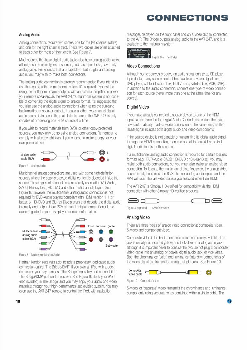
Analog connections require two cables, one for the left channel (white)
and one for the right channel (red). These two cables are often attachedto each other for most of their length. See Figure 7.
Most sources that have digital audio jacks also have analog audio jacks,although some older types of sources, such as tape decks, have only
analog jacks. For sources that are capable of both digital and analogaudio, you may wish to make both connections.
The analog audio connection is strongly recommended if you intend to
use the source with the multiroom system. It’s required if you will beusing the multiroom preamp outputs with an external amplifier to power
your remote speakers, as the AVR 247’s multiroom system is not capa-ble of converting the digital signal to analog format. It’s suggested that
you also use the analog audio connections when using the surroundback/multiroom speaker outputs, in case another two-channel digital
audio source is in use in the main listening area. The AVR 247 is only
capable of processing one PCM source at a time.If you wish to record materials from DVDs or other copy-protected
sources, you may only do so using analog connections. Remember tocomply with all copyright laws, if you choose to make a copy for your
own personal use.
Figure 7 – Analog Audio
Multichannel analog connections are used with some high-definition
sources where the copy-protected digital content is decoded inside the
source. These types of connections are usually used with DVD-Audio,SACD, Blu-ray Disc, HD-DVD and other multichannel players. See
Figure 8. However, the multichannel analog audio connection is not required for DVD-Audio players compliant with HDMI version 1.1 or
better, or HD-DVD and Blu-ray Disc players that decode the digital audiointernally and output linear PCM signals in digital format. Consult the
owner’s guide for your disc player for more information.
Figure 8 – Multichannel Analog Audio
Harman Kardon receivers also include a proprietary, dedicated audio
connection called “The Bridge/DMP”. If you own an iPod with a dock connector, you may purchase The Bridge separately and connect it toThe Bridge/DMP port on the receiver. See Figure 9. Dock your iPod
(not included) in The Bridge, and you may enjoy your audio and videomaterials through your high-performance audio/video system. You may
even use the AVR 247 remote to control the iPod, with navigation
messages displayed on the front panel and on a video display connectedto the AVR. The Bridge outputs analog audio to the AVR 247, and it is
available to the multiroom system.
Figure 9 – The Bridge
Video Connections
Although some sources produce an audio signal only (e.g., CD player,tape deck), many sources output both audio and video signals (e.g.,DVD player, cable television box, HDTV tuner, satellite box, VCR, DVR).
In addition to the audio connection, connect one type of video connec-tion for each source (never more than one at the same time for any
source).
Digital Video
If you have already connected a source device to one of the HDMI
inputs as explained in the Digital Audio Connections section, then youhave automatically made a video connection at the same time, as theHDMI signal includes both digital audio and video components.
If the source device is not capable of transmitting its digital audio signalthrough the HDMI connection, then use one of the coaxial or optical
digital audio inputs for the source.
If a multichannel analog audio connection is required for certain lossless
formats (e.g., DVD-Audio, SACD, HD-DVD or Blu-ray Disc), you maymake both audio connections, but you must also make an analog video
connection. To listen to the multichannel disc, first select the analog videosource input, then select the 6-/8-channel analog audio inputs, and the
AVR will retain the last video source you selected other than HDMI.
The AVR 247 is Simplay HD-verified for compatibility via the HDMIconnection with other Simplay HD-verified products.
Figure 4 (repeated) – HDMI Connection
Analog Video
There are three types of analog video connections: composite video,
S-video and component video.
Composite video is the basic connection most commonly available. The
jack is usually color-coded yellow, and looks like an analog audio jack,although it is important never to confuse the two. Do not plug a compositevideo cable into an analog or coaxial digital audio jack, or vice versa.
Both the chrominance (color) and luminance (intensity) components of the video signal are transmitted using a single cable. See Figure 10.
Figure 10 – Composite Video
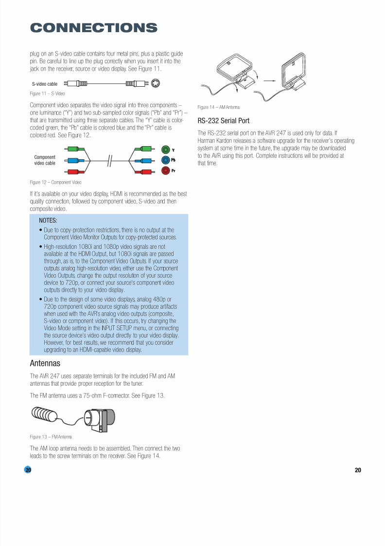
S-video, or “separate” video, transmits the chrominance and luminance
components using separate wires contained within a single cable. The
Composite
video cable
Multichannel
analog audio
cable (RC A)
Front Surround Center
Subwoofer
L
R
Analog audio
cable (RC A)
CONNECTIONS
8/2/2019 AVR247om lores
http://slidepdf.com/reader/full/avr247om-lores 20/76
20 20
CONNECTIONS
plug on an S-video cable contains four metal pins, plus a plastic guidepin. Be careful to line up the plug correctly when you insert it into the
jack on the receiver, source or video display. See Figure 11.
Figure 11 – S-Video
Component video separates the video signal into three components –
one luminance (“Y”) and two sub-sampled color signals (“Pb” and “Pr”) –that are transmitted using three separate cables. The “Y” cable is color-coded green, the “Pb” cable is colored blue and the “Pr” cable is
colored red. See Figure 12.
Figure 12 – Component Video
If it’s available on your video display, HDMI is recommended as the best quality connection, followed by component video, S-video and thencomposite video.
NOTES:
• Due to copy-protection restrictions, there is no output at theComponent Video Monitor Outputs for copy-protected sources.
• High-resolution 1080i and 1080p video signals are not available at the HDMI Output, but 1080i signals are passedthrough, as is, to the Component Video Outputs. If your sourceoutputs analog high-resolution video, either use the Component Video Outputs, change the output resolution of your sourcedevice to 720p, or connect your source’s component videooutputs directly to your video display.
• Due to the design of some video displays, analog 480p or720p component video source signals may produce artifactswhen used with the AVR’s analog v ideo outputs (composite,S-video or component video). If this occurs, try changing theVideo Mode setting in the INPUT SETUP menu, or connectingthe source device’s video output directly to your video display.However, for best results, we recommend that you considerupgrading to an HDMI-capable video display.
Antennas
The AVR 247 uses separate terminals for the included FM and AM
antennas that provide proper reception for the tuner.
The FM antenna uses a 75-ohm F-connector. See Figure 13.
Figure 13 – FM Antenna
The AM loop antenna needs to be assembled. Then connect the twoleads to the screw terminals on the receiver. See Figure 14.
Figure 14 – AM Antenna
RS-232 Serial Port
The RS-232 serial port on the AVR 247 is used only for data. If
Harman Kardon releases a software upgrade for the receiver’s operatingsystem at some time in the future, the upgrade may be downloaded
to the AVR using this port. Complete instructions will be provided at that time.
Componentvideo cable
S-video cable

8/2/2019 AVR247om lores
http://slidepdf.com/reader/full/avr247om-lores 21/76
21
SPEAKER PLACEMENT
Before you begin to connect cables, it is important to place your speakersin their correct locations in the room.
Optimally, the speakers should be placed in a circle with the listeningposition at its center. The distance from the listening position to the
video display forms the radius of the circle.
The speakers should be angled so that they directly face the listening
position.
Front Speaker Placement
The center speaker is placed either on top of, below or mounted on the
wall above or below the video display screen.
The front left and right speakers are placed along the circle, about 30
degrees from the center speaker and angled toward the listener.
It is best to place the front left/right and center speakers as close tothe same height as possible, preferably at about the same height as
the listener’s ears. In any event, the center speaker should be no morethan two feet above or below the left/right speakers.
Placement of the surround speakers depends on the number of speakers in your system. If you’re using only two speakers with the
AVR 247, place them in the front left and right positions, and skip tothe Installation section. However, Harman Kardon recommends usingthe AVR 247 in a 5.1- or 7.1-channel configuration for optimal
surround sound performance.
Figure 15 – Speaker Placement (5.1-Channel System)
Placement of Surround Speakers in a 5.1-ChannelSystem
The side surround speakers should be placed 110 degrees from thecenter speaker, that is, slightly behind and angled toward the listener.
If this isn’t feasible, place them behind the listener, with each surround
speaker facing the opposite-side front speaker. See Figure 15. Thesurround speakers may be placed a little higher than the listener’s ears.
Placement of Surround Speakers in a 7.1-ChannelSystem
In a 7.1-channel system, the side surround speakers are placed 90 degrees
from the center speaker, directly to either side of the listening position,which is different than in a 5.1-channel system. The surround back left
and right speakers are placed 150 degrees from the center speaker, ordirectly facing the opposite-side front speaker. See Figure 16.
Figure 16 – Speaker Placement (7.1-Channel System)
NOTE: Some speaker manufacturers offer 6.1-channel speakersystems, which are compatible with the 6.1-channel digital
surround sound formats available on DVD and elsewhere, suchas Dolby Digital EX and DTS-ES Discrete and Matrix modes.
We do not recommend using the AVR 247 in a 6.1-channelconfiguration. In fact, the 6.1-channel formats will sound better
when played through a 7.1-channel system. The same surroundback channel information is played through both surround back speakers, but with twice the power and clarity.
If you wish to use the AVR 247 with a 6.1-channel speakersystem, place the single surround back speaker directly behind
the listener, but do not connect it until after you have run theEzSet/EQ procedure for a 5.1-channel system. After EzSet/EQ
finishes, connect the surround back speaker to the Surround Back
C
90°
150°
90°150°
30° 30°
SUB
FRFL
SL
SBL SBR
SR
C
Alternate placement
for Side SurroundLeft Speaker
Alternate placementfor Side Surround
Right Speaker
110°
150°
110°
150°
30° 30°
SUB
FRFL
SL SR

8/2/2019 AVR247om lores
http://slidepdf.com/reader/full/avr247om-lores 22/76
22
SPEAKER PLACEMENT
Left Speaker Output. You will then need to follow the directions
in the Advanced Features section for manual setup of the sur-round back speaker.
Subwoofer Placement
The subwoofer’s location is less critical, since low-frequency sounds areomnidirectional. Placing the subwoofer close to a wall or in a corner willreinforce the low frequencies, and may create a “boomy” sound. You
may wish to experiment over time by placing the subwoofer where thelistener normally sits and then walking around the room until the low
frequencies sound best. Place the subwoofer in that spot.
NOTE: Your receiver will sound its best when the same modelloudspeaker is used for all positions (other than the subwoofer).
If that isn’t possible, try to use speakers made by the samemanufacturer.

8/2/2019 AVR247om lores
http://slidepdf.com/reader/full/avr247om-lores 23/76
23
INSTALLATION
You are now ready to connect your various components to your receiver.Before beginning, make sure that all components, including the AVR 247,are turned completely off and their power cords are unplugged. Don’tplug any of the power cords back in until you have finishedmaking all of your connections.
Remember that your receiver generates heat while it is on. Select alocation that leaves several inches of space on all sides of the receiver.It is preferable to avoid completely enclosing the receiver inside acabinet. It is also preferable to place components on separate shelves
rather than stacking them directly on top of the receiver. Some surfacefinishes are delicate. Try to select a location with a sturdy surface finish.
Step One – Connect the Speakers
If you have not yet done so, place your speakers in the listening room,as described in the Speaker Placement section above.
Connect the center, front left, front right, surround left, surroundright, surround back left and surround back right loudspeakers to the
corresponding speaker terminals on the AVR 247. See Figure 17.Remember to maintain the proper polarity by always connecting thepositive and negative terminals on each speaker to the positive and
negative terminals on the receiver. Use the Connection Color Guideon page 17 as a reference.
Figure 17 – Speaker Connections
NOTE: If you only have one surround back speaker, wait until
after you have run EzSet/EQ in the Initial Setup section beforeconnecting it to the Surround Back Left speaker outputs.
Step Two – Connect the Subwoofer
Connect the Subwoofer Output on the AVR 247 to the line-level input on
your subwoofer. See Figure 18. Consult the manufacturer’s guide for the
subwoofer for additional information.
Figure 18 – Subwoofer Connection
Step Three – Connect the Antennas
Connect the FM and AM antennas to their terminals. If you have purchased
an XM antenna module designed for connection to an XM Ready device,
such as the AVR 247, you may connect it now. To enjoy XM Radio,
remember to purchase a subscription and activate your antenna module.
More information is available at www.xmradio.com.See Figure 19.
Figure 19 – Antenna Connections
Step Four – Connect the Source Components
Use the Table A4 worksheet in the Appendix to note which connectionsyou will use for each of your source devices.
For each source, select a source input (Video 1, Video 2, Video 3, etc.).In Table 2 we recommend connecting certain types of sources to certainsource inputs to make it easier to program and use the remote control.
Decide which audio connections you will use. If your source device hasthem, use one of the HDMI, coaxial digital or optical digital audio connec-
tions. Referring to Table 2, we recommend you connect the DVD sourceto the Coaxial 1 input jack, and the source designated Video 2 to the
Optical 1 input jack. If you are using the HDMI inputs, then in most casesno other audio connection is required. If your source outputs video but not audio via its HDMI connection, then select any available coaxial or
optical digital audio input on the AVR to use with the source. If your HDMIsource plays DVD-Audio, SACD, HD-DVD, Blu-ray Discs or another multi-
channel audio format, connect its multichannel analog audio outputs tothe AVR 247’s 6-/8-Channel Inputs, and connect one of its analog video
outputs to a source input on the AVR 247 (e.g., Video 3). When youselect that source input, e.g., Video 3, select the 6-/8-Channel Inputs,and the AVR will automatically use the analog video input.
NOTE: The multichannel analog audio connection is not required for DVD-Audio players compliant with HDMI version
1.1 or better, or HD-DVD and Blu-ray Disc players that decodethe digital audio internally and output linear PCM signals in
digital format. Consult the owner’s guide for your disc playerfor more information.
In addition to the digital audio connections, we recommend that youconnect the analog audio connections for each source, as a backup tothe digital connections, for recording, for use with the multiroom system,
or in the event that you use all six of the digital audio inputs for otherdevices. For sources that don’t have digital audio outputs, you must use
the analog audio connections.
FM
AM
AVR 247
SUB
AVR 247
AVR 247
SR SLFR FL
SBR SBL
C
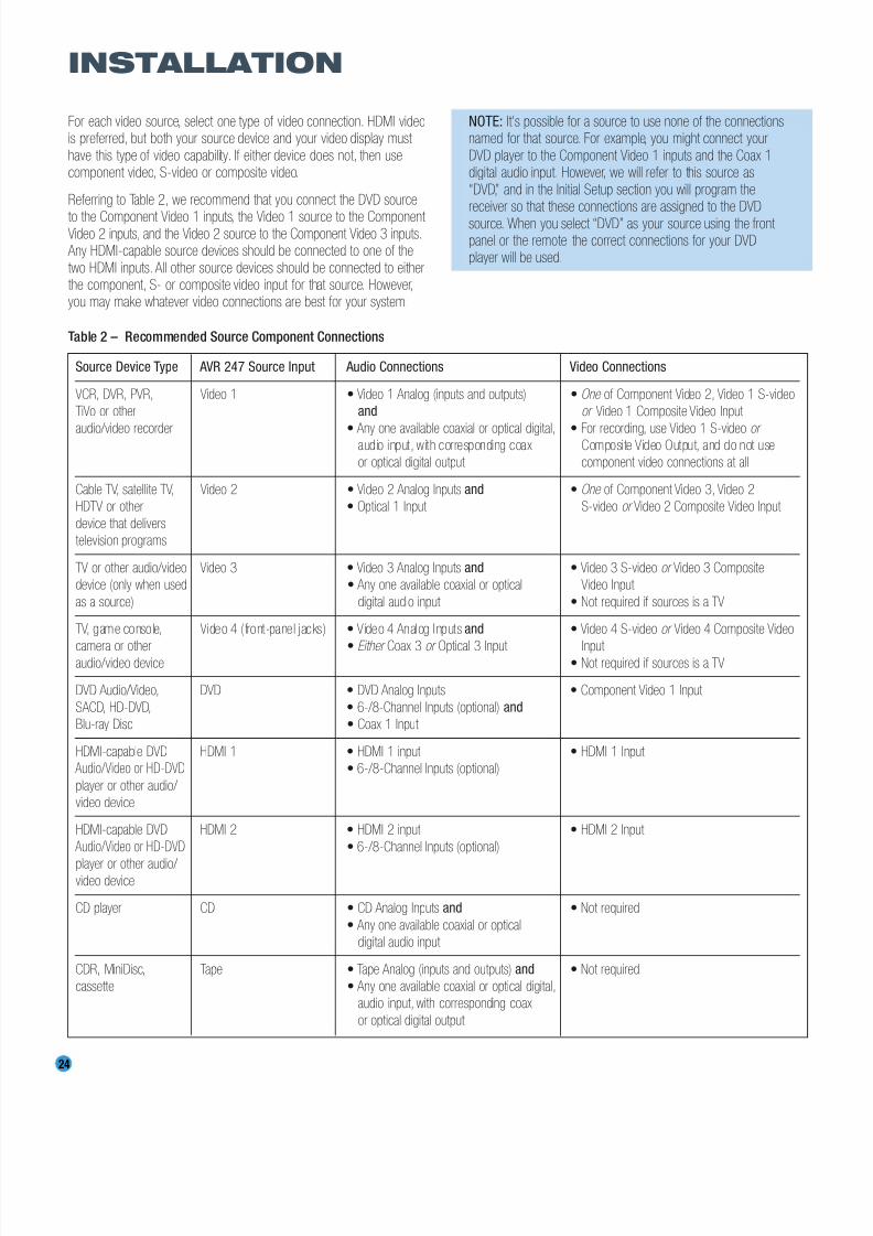
8/2/2019 AVR247om lores
http://slidepdf.com/reader/full/avr247om-lores 24/76
24
INSTALLATION
For each video source, select one type of video connection. HDMI videois preferred, but both your source device and your video display must
have this type of video capability. If either device does not, then usecomponent video, S-video or composite video.
Referring to Table 2, we recommend that you connect the DVD source
to the Component Video 1 inputs, the Video 1 source to the Component Video 2 inputs, and the Video 2 source to the Component Video 3 inputs.
Any HDMI-capable source devices should be connected to one of the
two HDMI inputs. All other source devices should be connected to eitherthe component, S- or composite video input for that source. However,you may make whatever video connections are best for your system.
NOTE: It’s possible for a source to use none of the connectionsnamed for that source. For example, you might connect your
DVD player to the Component Video 1 inputs and the Coax 1digital audio input. However, we will refer to this source as
“DVD,” and in the Initial Setup section you will program thereceiver so that these connections are assigned to the DVD
source. When you select “DVD” as your source using the front panel or the remote, the correct connections for your DVDplayer will be used.
Source Device Type AVR 247 Source Input Audio Connections Video Connections
VCR, DVR, PVR, Video 1 • Video 1 Analog (inputs and outputs) • One of Component Video 2, Video 1 S-video
TiVo or other and or Video 1 Composite Video Input
audio/video recorder • Any one available coaxial or optical digital, • For recording, use Video 1 S-video or audio input, with corresponding coax Composite Video Output, and do not use
or optical digital output component video connections at all
Cable TV, satellite TV, Video 2 • Video 2 Analog Inputs and • One of Component Video 3, Video 2
HDTV or other • Optical 1 Input S-video or Video 2 Composite Video Input
device that delivers
television programs
TV or other audio/video Video 3 • Video 3 Analog Inputs and • Video 3 S-video or Video 3 Composite
device (only when used • Any one available coaxial or optical Video Input
as a source) digital audio input • Not required if sources is a TV
TV, game console, Video 4 ( front-panel jacks) • Video 4 Analog Inputs and • Video 4 S-video or Video 4 Composite Video
camera or other • Either Coax 3 or Optical 3 Input Input audio/video device • Not required if sources is a TV
DVD Audio/Video, DVD • DVD Analog Inputs • Component Video 1 Input
SACD, HD-DVD, • 6-/8-Channel Inputs (optional) and
Blu-ray Disc • Coax 1 Input
HDMI-capable DVD HDMI 1 • HDMI 1 input • HDMI 1 Input
Audio/Video or HD-DVD • 6-/8-Channel Inputs (optional)
player or other audio/
video device
HDMI-capable DVD HDMI 2 • HDMI 2 input • HDMI 2 Input
Audio/Video or HD-DVD • 6-/8-Channel Inputs (optional)
player or other audio/ video device
CD player CD • CD Analog Inputs and • Not required
• Any one available coaxial or optical
digital audio input
CDR, MiniDisc, Tape • Tape Analog (inputs and outputs) and • Not required
cassette • Any one available coaxial or optical digital,
audio input, with corresponding coax
or optical digital output
Table 2 – Recommended Source Component Connections
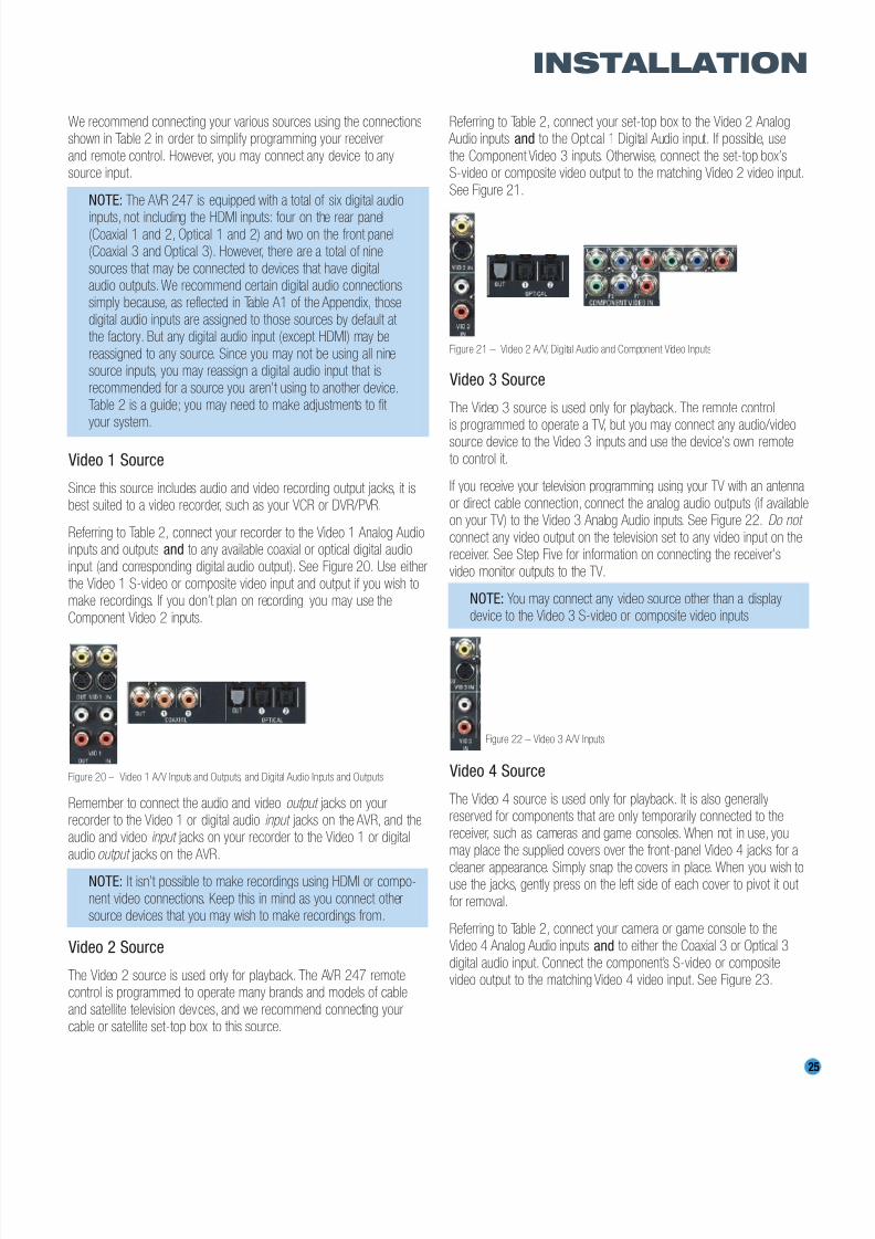
8/2/2019 AVR247om lores
http://slidepdf.com/reader/full/avr247om-lores 25/76
25
INSTALLATION
We recommend connecting your various sources using the connectionsshown in Table 2 in order to simplify programming your receiver
and remote control. However, you may connect any device to anysource input.
NOTE: The AVR 247 is equipped with a total of six digital audio
inputs, not including the HDMI inputs: four on the rear panel(Coaxial 1 and 2, Optical 1 and 2) and two on the front panel(Coaxial 3 and Optical 3). However, there are a total of nine
sources that may be connected to devices that have digitalaudio outputs.We recommend certain digital audio connectionssimply because, as reflected in Table A1 of the Appendix, those
digital audio inputs are assigned to those sources by default at the factory. But any digital audio input (except HDMI) may be
reassigned to any source. Since you may not be using all ninesource inputs, you may reassign a digital audio input that is
recommended for a source you aren’t using to another device.Table 2 is a guide; you may need to make adjustments to fit your system.
Video 1 Source
Since this source includes audio and video recording output jacks, it isbest suited to a video recorder, such as your VCR or DVR/PVR.
Referring to Table 2, connect your recorder to the Video 1 Analog Audioinputs and outputs and to any available coaxial or optical digital audioinput (and corresponding digital audio output). See Figure 20. Use either
the Video 1 S-video or composite video input and output if you wish tomake recordings. If you don’t plan on recording, you may use the
Component Video 2 inputs.
Figure 20 – Video 1 A/V Inputs and Outputs, and Digital Audio Inputs and Outputs
Remember to connect the audio and video output jacks on yourrecorder to the Video 1 or digital audio input jacks on the AVR, and theaudio and video input jacks on your recorder to the Video 1 or digital
audio output jacks on the AVR.
NOTE: It isn’t possible to make recordings using HDMI or compo-
nent video connections. Keep this in mind as you connect othersource devices that you may wish to make recordings from.
Video 2 Source
The Video 2 source is used only for playback. The AVR 247 remotecontrol is programmed to operate many brands and models of cable
and satellite television devices, and we recommend connecting yourcable or satellite set-top box to this source.
Referring to Table 2, connect your set-top box to the Video 2 Analog Audio inputs and to the Optical 1 Digital Audio input. If possible, use
the Component Video 3 inputs. Otherwise, connect the set-top box’sS-video or composite video output to the matching Video 2 video input.
See Figure 21.
Figure 21 – Video 2 A/V, Digital Audio and Component Video Inputs
Video 3 Source
The Video 3 source is used only for playback. The remote controlis programmed to operate a TV, but you may connect any audio/videosource device to the Video 3 inputs and use the device’s own remote
to control it.
If you receive your television programming using your TV with an antenna
or direct cable connection, connect the analog audio outputs (if availableon your TV) to the Video 3 Analog Audio inputs. See Figure 22. Do not
connect any video output on the television set to any video input on thereceiver. See Step Five for information on connecting the receiver’s
video monitor outputs to the TV.
NOTE: You may connect any video source other than a displaydevice to the Video 3 S-video or composite video inputs.
Figure 22 – Video 3 A/V Inputs
Video 4 Source
The Video 4 source is used only for playback. It is also generallyreserved for components that are only temporarily connected to the
receiver, such as cameras and game consoles. When not in use, youmay place the supplied covers over the front-panel Video 4 jacks for a
cleaner appearance. Simply snap the covers in place. When you wish touse the jacks, gently press on the left side of each cover to pivot it out
for removal.
Referring to Table 2, connect your camera or game console to theVideo 4 Analog Audio inputs and to either the Coaxial 3 or Optical 3
digital audio input. Connect the component’s S-video or compositevideo output to the matching Video 4 video input. See Figure 23.
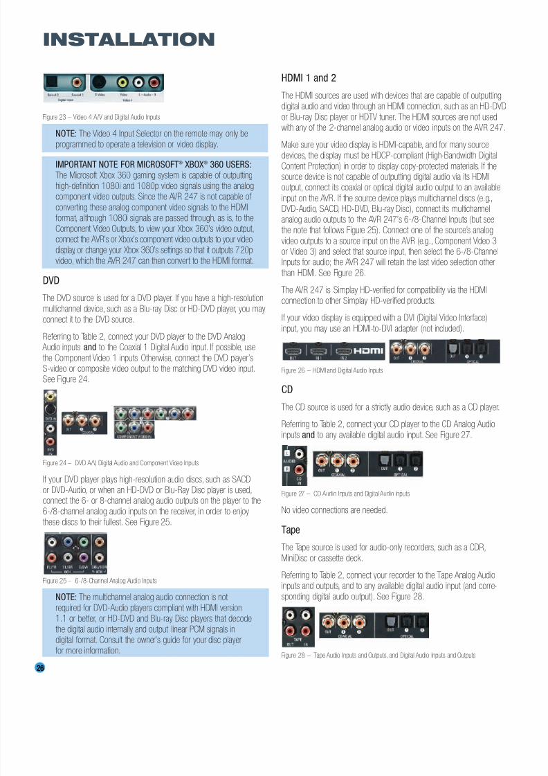
8/2/2019 AVR247om lores
http://slidepdf.com/reader/full/avr247om-lores 26/76
26
INSTALLATION
Figure 23 – Video 4 A/V and Digital Audio Inputs
NOTE: The Video 4 Input Selector on the remote may only beprogrammed to operate a television or video display.
IMPORTANT NOTE FOR MICROSOFT® XBOX® 360 USERS:The Microsoft Xbox 360 gaming system is capable of outputting
high-definition 1080i and 1080p video signals using the analogcomponent video outputs. Since the AVR 247 is not capable of
converting these analog component video signals to the HDMIformat, although 1080i signals are passed through, as is, to the
Component Video Outputs, to view your Xbox 360’s video output,connect the AVR’s or Xbox’s component video outputs to your videodisplay, or change your Xbox 360’s settings so that it outputs 720p
video, which the AVR 247 can then convert to the HDMI format.
DVD
The DVD source is used for a DVD player. If you have a high-resolution
multichannel device, such as a Blu-ray Disc or HD-DVD player, you mayconnect it to the DVD source.
Referring to Table 2, connect your DVD player to the DVD Analog Audio inputs and to the Coaxial 1 Digital Audio input. If possible, use
the Component Video 1 inputs. Otherwise, connect the DVD player’sS-video or composite video output to the matching DVD video input.See Figure 24.
Figure 24 – DVD A/V, Digital Audio and Component Video Inputs
If your DVD player plays high-resolution audio discs, such as SACDor DVD-Audio, or when an HD-DVD or Blu-Ray Disc player is used,connect the 6- or 8-channel analog audio outputs on the player to the
6-/8-channel analog audio inputs on the receiver, in order to enjoythese discs to their fullest. See Figure 25.
Figure 25 – 6-/8-Channel Analog Audio Inputs
NOTE: The multichannel analog audio connection is not
required for DVD-Audio players compliant with HDMI version1.1 or better, or HD-DVD and Blu-ray Disc players that decode
the digital audio internally and output linear PCM signals indigital format. Consult the owner’s guide for your disc playerfor more information.
HDMI 1 and 2
The HDMI sources are used with devices that are capable of outputtingdigital audio and video through an HDMI connection, such as an HD-DVD
or Blu-ray Disc player or HDTV tuner. The HDMI sources are not usedwith any of the 2-channel analog audio or video inputs on the AVR 247.
Make sure your video display is HDMI-capable, and for many sourcedevices, the display must be HDCP-compliant (High-Bandwidth Digital
Content Protection) in order to display copy-protected materials. If thesource device is not capable of outputting digital audio via its HDMIoutput, connect its coaxial or optical digital audio output to an available
input on the AVR. If the source device plays multichannel discs (e.g.,DVD-Audio, SACD, HD-DVD, Blu-ray Disc), connect its multichannel
analog audio outputs to the AVR 247’s 6-/8-Channel Inputs (but seethe note that follows Figure 25). Connect one of the source’s analog
video outputs to a source input on the AVR (e.g., Component Video 3or Video 3) and select that source input, then select the 6-/8-ChannelInputs for audio; the AVR 247 will retain the last video selection other
than HDMI. See Figure 26.
The AVR 247 is Simplay HD-verified for compatibility via the HDMI
connection to other Simplay HD-verified products.
If your video display is equipped with a DVI (Digital Video Interface)
input, you may use an HDMI-to-DVI adapter (not included).
Figure 26 – HDMI and Digital Audio Inputs
CD
The CD source is used for a strictly audio device, such as a CD player.
Referring to Table 2, connect your CD player to the CD Analog Audio
inputs and to any available digital audio input. See Figure 27.
Figure 27 – CD Audio Inputs and Digital Audio Inputs
No video connections are needed.
Tape
The Tape source is used for audio-only recorders, such as a CDR,MiniDisc or cassette deck.
Referring to Table 2, connect your recorder to the Tape Analog Audio
inputs and outputs, and to any available digital audio input (and corre-sponding digital audio output). See Figure 28.
Figure 28 – Tape Audio Inputs and Outputs, and Digital Audio Inputs and Outputs
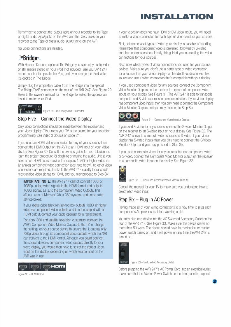
8/2/2019 AVR247om lores
http://slidepdf.com/reader/full/avr247om-lores 27/76
27
INSTALLATION
Remember to connect the output jacks on your recorder to the Tapeor digital audio input jacks on the AVR, and the input jacks on your
recorder to the Tape or digital audio output jacks on the AVR.
No video connections are needed.
With Harman Kardon’s optional The Bridge, you can enjoy audio, video
or still images stored on your iPod (not included), use your AVR 247remote control to operate the iPod, and even charge the iPod whileit’s docked in The Bridge.
Simply plug the proprietary cable from The Bridge into the specialThe Bridge/DMP connector on the rear of the AVR 247. See Figure 29.
Refer to the owner’s manual for The Bridge to select the appropriateinsert to match your iPod.
Figure 29 –The Bridge/DMP Connector
Step Five – Connect the Video Display
Only video connections should be made between the receiver andyour video display (TV), unless your TV is the source for your televisionprogramming (see Video 3 Source on page 24).
If you used an HDMI video connection for any of your sources, thenconnect the HDMI Output on the AVR to an HDMI input on your video
display. See Figure 30. Consult the owner’s guide for your television tolearn the proper procedure for disabling or muting the audio. Unless you
have a non-HDMI source device that outputs 1080i or higher video viaan analog component video connection (see note below), no other videoconnections are required, thanks to the AVR 247’s ability to transcode
most analog video signals to HDMI, and you may proceed to Step Six.
IMPORTANT NOTE: The AVR 247 cannot convert 1080i or
1080p analog video signals to the HDMI format and outputs1080i signals, as is, to the Component Video Outputs. This
affects users of Microsoft Xbox 360 systems and some olderset-top boxes.
If your digital cable television set-top box outputs 1080i or highervideo via component video outputs and is not equipped with an
HDMI output, contact your cable operator for a replacement.
For Xbox 360 and satellite television customers, connect the AVR’s Component Video Monitor Outputs to the TV, or change
the settings on your source device to ensure that it outputs only720p video through its component video outputs, which the AVR
can convert to the HDMI format. Although you could connect the source device’s component video outputs directly to yourvideo display, you would then have to select the correct video
input on the display, depending on which source input on the AVR was in use.
Figure 30 – HDMI Output
If your television does not have HDMI or DVI video inputs, you will needto make a video connection for each type of video used for your sources.
First, determine what types of video your display is capable of handling.Remember that component video is preferred, followed by S-video
and then composite video. Ideally, this guided you in selecting the video
connections for your sources.
Next, note which types of video connections you used for your sourcedevices. Make sure you didn’t use a better type of video connection
for a source than your video display can handle. If so, disconnect thesource and use a video connection that’s compatible with your display.
If you used component video for any sources, connect the Component
Video Monitor Outputs on the receiver to one set of component videoinputs on your display. See Figure 31. The AVR 247 is able to transcode
composite and S-video sources to component video. If your video displayhas component video inputs, then you only need to connect the Component
Video Monitor Outputs and you may proceed to Step Six.
Figure 31 – Component Video Monitor Outputs
If you used S-video for any sources, connect the S-video Monitor Output on the receiver to an S-video input on your display. See Figure 32. The
AVR 247 converts composite video sources to S-video. If your videodisplay has S-video inputs, then you only need to connect the S-Video
Monitor Output and you may proceed to Step Six.
If you used composite video for any sources, but not component video
or S-video, connect the Composite Video Monitor output on the receiverto a composite video input on the display. See Figure 32.
Figure 32 – S-Video and Composite Video Monitor Outputs
Consult the manual for your TV to make sure you understand how toselect each video input.
Step Six – Plug in AC Power
Having made all of your wiring connections, it is now time to plug eachcomponent’s AC power cord into a working outlet.
You may plug one device into the AC Switched Accessory Outlet on therear of the AVR 247. See Figure 33. Make sure this device draws no
more than 50 watts. The device should have its mechanical or masterpower switch turned on, and it will power on any time the AVR 247 isturned on.
Figure 33 – Switched AC Accessory Outlet
Before plugging the AVR 247’s AC Power Cord into an electrical outlet,
make sure that the Master Power Switch on the front panel is popped
TheBridgeTM
8/2/2019 AVR247om lores
http://slidepdf.com/reader/full/avr247om-lores 28/76
out so that the word OFF appears on its top. Gently press the button toturn the switch off. This will prevent the possibility of damaging the AVR
in case of a transient power surge.
Step Seven – Insert Batteries in Remote
The AVR 247 remote control uses three AAA batteries, which are included.
To remove the battery cover located on the back of the remote,firmly press the ridged depression and slide the cover toward the top
of the remote.
Insert the batteries, as shown in Figure 34, making sure to observe
the correct polarity.
Figure 34 – Remote Battery Compartment
When using the remote, remember to point the lens toward the front
panel of the AVR 247. Make sure no objects, such as furniture, areblocking the remote’s path to the receiver. Bright lights, fluorescent lights
and plasma video displays may interfere with the remote’s functioning.The remote has a range of about 20 feet, depending on the lighting
conditions. It may be used at an angle of up to 30 degrees to eitherside of the AVR.
If the remote seems to operate intermittently, or if pressing a button
on the remote does not cause the AVR Selector or one of the Input Selectors to light up, then make sure the batteries have been inserted
correctly, or replace all three batteries with fresh ones.
Step Eight – Program Sources Into the Remote
The AVR 247 remote not only is capable of controlling the receiver,
but it may also be programmed to control many brands and models of VCRs, DVD players, CD players, cable boxes, satellite receivers, cassette
decks and TVs, as well as an iPod docked in The Bridge.
It may help to think of the remote as a book with pages. Each “page”
represents the button functions for a different device. In order to accessthe functions for a particular device, you first need to turn to that page;that is, switch the remote to that device mode. This is done by pressing
the AVR Button to access the codes that control the receiver, or theInput Selector Buttons to access the codes for the devices programmed
into the remote.
You may have noticed that three of the Input Selectors look different
from the others (see Figure 35). For the DVD/CD, TAPE/The Bridge andHDMI 1/HDMI 2 Selectors, there is a primary source, the name of whichis printed on the button, and a secondary source, the name of which is
printed in green above the button.
When the remote is in the device mode for the primary source, e.g., DVD,pressing the device selector will cause it to light up in red.When the
remote is in the secondary source’s device mode, the selector will light up in green when pressed.
To switch between the primary and secondary device modes, press the
selector twice quickly in succession. The selector will retain this selectionuntil the next time you toggle between the primary and secondary devicemodes. That is, if you press the DVD/CD Selector twice quickly so that
the CD source is activated, then press another source selector, such asVideo 1, the next time you press the DVD/CD Selector, the remote willreturn to the CD device mode.
The AVR 247’s remote is factory-programmed to control an iPoddocked in The Bridge and many Harman Kardon DVD and CD players.
If you have other source devices in your system, follow these steps toprogram the correct codes into the remote.
1. Using the codes in Tables A9–A16 of the Appendix, look up theproduct type (e.g., DVD, cable TV box) and the brand name of your
source. The number(s) listed is/are potential candidates for thecorrect code set for your particular device.
2. Turn on your source device.
3. This step places the remote in program mode, and varies slightly,depending on which Input Selector is being programmed. Refer to
Figure 35.
a) DVD, Tape, Video 1, Video 2, Video 3 and Video 4 Sources:Press and hold the Input Selector until the Program Indicator LEDstarts to flash, then release it. Follow the directions in Step 4, below.
b) CD Source: Press the DVD/CD Input Selector twice quickly so
that it turns green, hold it until the Program LED starts to flash,then release. Follow the directions in Step 4, below.
c) HDMI 1 Source: Press and hold the Input Selector until it turnsred and the Program LED starts to flash, then release it. Next,
press the Input Selector that corresponds to the device type youwant to program into the HDMI 1 mode, i.e., DVD, VCR/PVR or
CBL/SAT. Then follow the directions in Step 4, below.
d) HDMI 2 Source: Press and release the Input Selector once, then
quickly press the Input Selector again so that it turns green. Holdit until the Program LED starts to flash, then release it. Next, pressthe Input Selector that corresponds to the device type you want to
program into the HDMI 2 mode, i.e., DVD, VCR/PVR or CBL/SAT.Then follow the directions in Step 4, below.
Figure 35 – Input Selectors
28
INSTALLATION
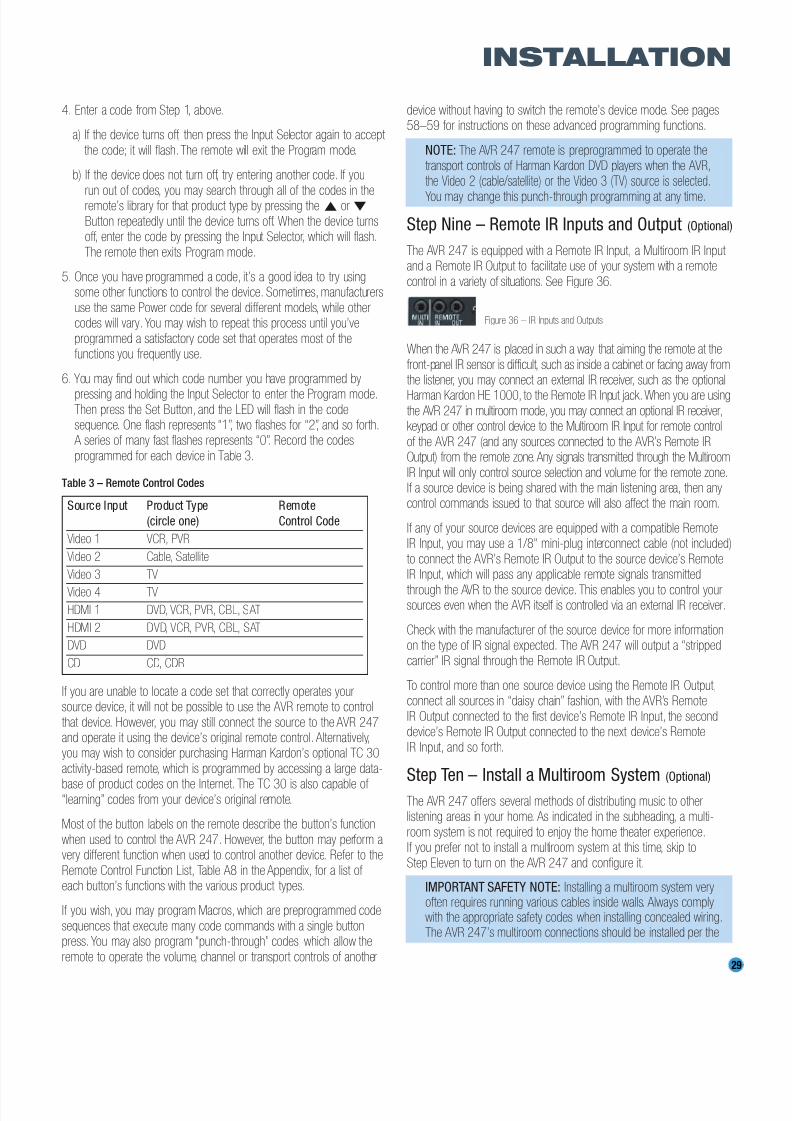
8/2/2019 AVR247om lores
http://slidepdf.com/reader/full/avr247om-lores 29/76
29
INSTALLATION
4. Enter a code from Step 1, above.
a) If the device turns off, then press the Input Selector again to accept
the code; it will flash. The remote will exit the Program mode.
b) If the device does not turn off, try entering another code. If you
run out of codes, you may search through all of the codes in theremote’s library for that product type by pressing the ⁄ or ¤
Button repeatedly until the device turns off. When the device turnsoff, enter the code by pressing the Input Selector, which will flash.
The remote then exits Program mode.
5. Once you have programmed a code, it’s a good idea to try usingsome other functions to control the device. Sometimes, manufacturers
use the same Power code for several different models, while othercodes will vary. You may wish to repeat this process until you’ve
programmed a satisfactory code set that operates most of thefunctions you frequently use.
6. You may find out which code number you have programmed by
pressing and holding the Input Selector to enter the Program mode.Then press the Set Button, and the LED will flash in the codesequence. One flash represents “1”, two flashes for “2”, and so forth.
A series of many fast flashes represents “0”. Record the codes
programmed for each device in Table 3.
Table 3 – Remote Control Codes
If you are unable to locate a code set that correctly operates yoursource device, it will not be possible to use the AVR remote to control
that device. However, you may still connect the source to the AVR 247and operate it using the device’s original remote control. Alternatively,you may wish to consider purchasing Harman Kardon’s optional TC 30
activity-based remote, which is programmed by accessing a large data-
base of product codes on the Internet. The TC 30 is also capable of “learning” codes from your device’s original remote.
Most of the button labels on the remote describe the button’s function
when used to control the AVR 247. However, the button may perform avery different function when used to control another device. Refer to the
Remote Control Function List, Table A8 in the Appendix, for a list of each button’s functions with the various product types.
If you wish, you may program Macros, which are preprogrammed code
sequences that execute many code commands with a single buttonpress. You may also program “punch-through” codes, which allow the
remote to operate the volume, channel or transport controls of another
device without having to switch the remote’s device mode. See pages58–59 for instructions on these advanced programming functions.
NOTE: The AVR 247 remote is preprogrammed to operate thetransport controls of Harman Kardon DVD players when the AVR,
the Video 2 (cable/satellite) or the Video 3 (TV) source is selected.
You may change this punch-through programming at any time.
Step Nine – Remote IR Inputs and Output (Optional)
The AVR 247 is equipped with a Remote IR Input, a Multiroom IR Input and a Remote IR Output to facilitate use of your system with a remote
control in a variety of situations. See Figure 36.
Figure 36 – IR Inputs and Outputs
When the AVR 247 is placed in such a way that aiming the remote at the
front-panel IR sensor is difficult, such as inside a cabinet or facing away fromthe listener, you may connect an external IR receiver, such as the optional
Harman Kardon HE 1000, to the Remote IR Input jack.When you are usingthe AVR 247 in multiroom mode, you may connect an optional IR receiver,keypad or other control device to the Multiroom IR Input for remote control
of the AVR 247 (and any sources connected to the AVR’s Remote IROutput) from the remote zone. Any signals transmitted through the Multiroom
IR Input will only control source selection and volume for the remote zone.If a source device is being shared with the main listening area, then anycontrol commands issued to that source will also affect the main room.
If any of your source devices are equipped with a compatible RemoteIR Input, you may use a 1/8" mini-plug interconnect cable (not included)
to connect the AVR’s Remote IR Output to the source device’s RemoteIR Input, which will pass any applicable remote signals transmitted
through the AVR to the source device. This enables you to control yoursources even when the AVR itself is controlled via an external IR receiver.
Check with the manufacturer of the source device for more informationon the type of IR signal expected. The AVR 247 will output a “strippedcarrier” IR signal through the Remote IR Output.
To control more than one source device using the Remote IR Output,connect all sources in “daisy chain” fashion, with the AVR’s Remote
IR Output connected to the first device’s Remote IR Input, the seconddevice’s Remote IR Output connected to the next device’s Remote
IR Input, and so forth.
Step Ten – Install a Multiroom System (Optional)
The AVR 247 offers several methods of distributing music to otherlistening areas in your home. As indicated in the subheading, a multi-
room system is not required to enjoy the home theater experience.If you prefer not to install a multiroom system at this time, skip to
Step Eleven to turn on the AVR 247 and configure it.
IMPORTANT SAFETY NOTE: Installing a multiroom system veryoften requires running various cables inside walls. Always complywith the appropriate safety codes when installing concealed wiring.The AVR 247’s multiroom connections should be installed per the
Source Input Product Type Remote
(circle one) Control Code
Video 1 VCR, PVR
Video 2 Cable, Satellite
Video 3 TV
Video 4 TV
HDMI 1 DVD, VCR, PVR, CBL, SAT
HDMI 2 DVD, VCR, PVR, CBL, SAT
DVD DVD
CD CD, CDR

8/2/2019 AVR247om lores
http://slidepdf.com/reader/full/avr247om-lores 30/76
30
INSTALLATION
requirements of all applicable state and local building codes, aswell as NEC (National Electrical Code) requirements. Check withyour local authorities as needed to ensure that all wiring insidewalls is installed in compliance with the proper standards. Failureto do so may present a potential safety hazard. If you have anydoubt about your ability to work with electrical and telecommuni-
cations wiring, you are advised to hire a professional licensedelectrician or custom installer to install the multiroom system.
1. Connect the remote room’s speakers directly to the SurroundBack/Multiroom Speaker Outputs. See Figure 37.
Figure 37 – Surround Back/Multiroom Speaker Outputs
If you do not require a full 7.1-channel system in your main listeningarea, and you prefer not to purchase an external amplifier to power
a pair of remote speakers, you may reassign the AVR 247’s SurroundBack amplifier channels to power the speakers. Your main system will
be limited to 5.1 channels, which affects your ability to enjoy themany DVDs and other programs recorded in 6.1 and 7.1 channels.
2. Connect an external amplifier to the Surround Back/MultiroomPreamp Outputs. See Figure 38.
Figure 38 – Surround Back/Multiroom Preamp Outputs
This method may be used when it is more important to distribute audioto additional rooms than to have a full 7.1-channel system in the main
listening area, as it is still necessary to assign the surround back amplifierchannels to the remote zone, limiting the main system to 5.1 channels.This method also requires you to provide an additional component, that
is, the amplifier. However, this method may be used to increase thenumber of remote rooms in the system when you are also using the
Surround Back/Multiroom Speaker Outputs.
It is recommended that you place the amplifier in the same room as
the AVR 247 so that a shorter length of interconnect cable is used witha long run of speaker wire to the remote room, rather than placing the
amplifier in the remote room, which necessitates a long run of intercon-nect cable that would then be subject to signal degradation. Dependingon the number of channels available in your amplifier, you may distribute
the AVR 247’s analog audio signal to a single pair of speakers for two-channel listening, to several pairs of speakers located in several different
rooms, or when listening to mono FM radio, to individual speakersplaced in different rooms. Use the Tuning Mode Button to select the
mono mode for FM radio.
In addition to the audio signal, you will usually wish to connect an IRcontrol device to the AVR 247’s Multiroom IR Input so that listeners in
the remote room may turn the multiroom system on or off, select a
source input, control the source device connected to that input andadjust the volume in the remote zone.
NOTE: Only analog audio sources are available to the multiroom
system.
Step Eleven – Turn On the AVR 247
Two steps are required the first time you turn on the AVR 247.
1. Gently press the Master Power Switch until the word OFF is no longervisible. The Power Indicator above the two power switches should
light up in amber, indicating that the AVR is in Standby mode and isready to be turned on. See Figure 39. Normally, you may leave theMaster Power Switch in the ON position, even when the receiver is
not being used.
Figure 39 – Power Switches
2. There are several ways in which the AVR 247 may be turned on fromStandby mode.
a) Press the Standby/On Switch on the front panel. See Figure 39.
b) Press the Source Select Button on the front panel. See Figure 40.
Figure 40 – Source Select Button
c) Using the remote, press any one of these buttons: AVR, DVD/CD,TAPE/The Bridge, HDMI 1/2, VID1, VID2, VID3, VID4, XM,AM/FMor 6/8CH. See Figure 41.
Figure 41 – AVR and Input Selectors
NOTE: Any time you press one of the Input Selectors on theremote (i.e., DVD/CD, TAPE/The Bridge, HDMI 1/HDMI 2, VID1,
VID2, VID3 or VID4), the remote will switch modes so that it willonly transmit the codes programmed to operate that device. Inorder to control the receiver, press the AVR Button to return the
remote to AVR mode.
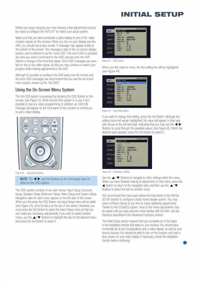
8/2/2019 AVR247om lores
http://slidepdf.com/reader/full/avr247om-lores 31/76
31
INITIAL SETUP
Before you begin enjoying your new receiver, a few adjustments shouldbe made to configure the AVR 247 to match your actual system.
Make sure that you have connected a video display to one of the videomonitor outputs on the receiver. When you turn on your display and the
AVR, you should see a blue screen. A message may appear briefly at
the bottom of the screen. This message is part of the on-screen displaysystem, and is referred to as the “semi-OSD”. The semi-OSD is activatedany time you send a command to the AVR, and any time the AVRdetects a change in the incoming signal. Semi-OSD messages are over-
laid on top of any video signal, so that you may continue to watch yourprogram while making adjustments to the AVR.
Although it’s possible to configure the AVR using only the remote andthe semi-OSD messages, we recommend that you use the full-screen
menu system, known as the “full-OSD”.
Using the On-Screen Menu System
The full-OSD system is accessed by pressing the OSD Button on the
remote. See Figure 42. While the full-OSD system is in use, it isn’t possible to see any video programming. In addition, an OSD ONmessage will appear on the front panel of the receiver to remind you
to use a video display.
Figure 42 – Navigation Buttons
NOTE: The ‹ / › and Set Buttons on the front panel have noeffect on the OSD system.
The OSD system consists of six main menus: Input Setup, Surround
Setup, Speaker Setup, Multiroom Setup, Video Setup and System Setup.
Navigation tabs for each menu appear on the left side of the screen.When you first press the OSD Button, the Input Setup menu will be visible
(see Figure 43), since its tab is at the top of the screen. However, youmust press the Set Button to select the Input Setup menu so that you
can make any necessary adjustments. If you wish to select anothermenu, use the⁄ / ¤ Buttons to highlight the tab for the desired menu,
and press the Set Button to select it.
Figure 43 – OSD System
When you first select a menu, the first setting line will be highlighted(see Figure 44).
Figure 44 – Input Setup Menu
If you wish to change that setting, press the Set Button. Although the
setting name will remain highlighted, the value will appear in blue typewith arrows to the left and right, indicating that you may use the‹ / ›
Buttons to scroll through the available values. See Figure 45. When the
desired value appears, press the Set Button to select it.
Figure 45 – Changing a Setting
Use the ⁄ / ¤ Buttons to navigate to other settings within the menu.When you have finished making all adjustments in that menu, press the
‹ Button to return to the navigation tabs, and then use the⁄ / ¤
Buttons to select the tab for another menu.
We recommend that most users follow the instructions in this INITIALSETUP section to configure a basic home theater system. You may
return to these menus at any time to make additional adjustments.Thanks to the EzSet/EQ system, most of the menu adjustments maybe saved until you have become more familiar with the AVR, and are
therefore described in the Advanced Functions section.
The Initial Setup section requires that you complete all of the steps
in the Installation section that apply to your receiver. You should haveconnected all of your loudspeakers and a video display, as well as your
source devices. You should be able to turn on the receiver and view ablue screen on your video display. If necessary, reread the InstallationSection before continuing.

8/2/2019 AVR247om lores
http://slidepdf.com/reader/full/avr247om-lores 32/76
32
INITIAL SETUP
Configure the AVR 247 Using EzSet/EQ
One of the most important and perhaps often overlooked aspects of
setting up a home theater system is to calibrate the receiver to matchthe loudspeakers, which enables the AVR to perform at its best.
Until recently, most receivers required the user to perform the calibrationand configuration manually, a somewhat tedious process that called for
a good ear or the purchase of an SPL (sound-pressure level) meter. Although you may configure the AVR 247 manually, as described inthe Advanced Features section, we recommend that most users take
advantage of our signature EzSet/EQ system.
Before beginning, eliminate extraneous background noise that might
affect the results, such as noisy air conditioning. Try to avoid makingany loud noises while running EzSet/EQ.
IMPORTANT SAFETY NOTE: During the EzSet/EQ procedure,a series of very loud test tones will be played through all of the
speakers. Avoid sitting or standing close to any one speaker
during the procedure. If you are particularly sensitive to loudnoises, you may wish to leave the room and have someone
else run EzSet/EQ.
Step One – Place the included EzSet/EQ microphone in the listening
position, or in the center of the room, at about the same height as thelisteners’ ears. The microphone features a threaded insert on the bottom
so that it can be mounted on a camera tripod for stability.
Step Two – Plug the EzSet/EQ microphone into the Headphone
Jack/EzSet/EQ Microphone Input Jack on the front of the receiver.See Figure 46.
Figure 46 – Plug EzSet/EQ microphone into receiver.
Step Three – Make sure that the AVR 247 and the video display areturned on. Press the OSD Button to display the menu system. SeeFigure 43. Use the ⁄ / ¤ Buttons to move the cursor to the Speaker
Setup tab, and then press the Set Button to select the Speaker Setupmenu. See Figure 47.
Figure 47 – Speaker Setup Menu Screen
Select the “Auto Configuration” setting, and the screen shown in Figure48 will appear to direct you to plug the EzSet/EQ microphone into the
Headphone Jack.
Figure 48 – EzSet/EQ Screen
Step Four – After you select “Continue”, the screen shown in Figure 49
will appear. Although the AVR 247 may be used with up to eight speakers,you may have elected not to install surround back speakers at this time,
or you may have decided to use the surround back speaker channels topower speakers in the remote room of a multiroom system. This screendirects you to program EzSet/EQ for a 5.1- or 7.1-channel configuration.
Select the setting that reflects the number of speakers installed in yoursystem, and EzSet/EQ will do the rest automatically!
Figure 49 – EzSet/EQ: Number of Speakers
NOTE: If you are using fewer than five main speakers in yoursystem, then it will not be possible to configure your speakers
using EzSet/EQ, and you will need to select Manual Configurationas described in the Advanced Functions section. If you haveselected a 6.1-channel configuration, using only a single surround
back speaker, it is possible to use a combination of EzSet/EQautomatic configuration for 5.1 speakers, connect the single
surround back speaker to the left Surround Back Speaker Output,and then configure the surround back speaker manually, as
described in the Advanced Functions section. However, we donot recommend the 6.1-channel configuration.
If you have forgotten to plug in the EzSet/EQ microphone, the warning
screen shown in Figure 50 will appear as a reminder.
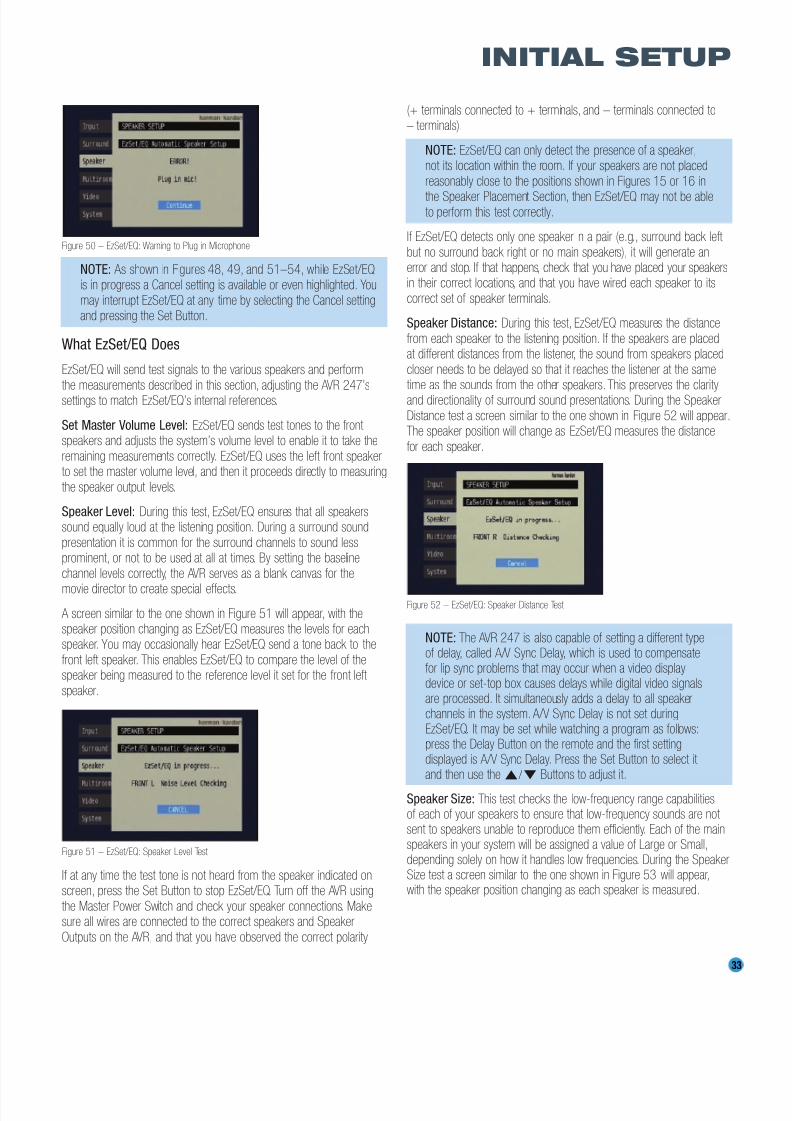
8/2/2019 AVR247om lores
http://slidepdf.com/reader/full/avr247om-lores 33/76
33
INITIAL SETUP
Figure 50 – EzSet/EQ: Warning to Plug in Microphone
NOTE: As shown in Figures 48, 49, and 51–54, while EzSet/EQis in progress a Cancel setting is available or even highlighted. You
may interrupt EzSet/EQ at any time by selecting the Cancel settingand pressing the Set Button.
What EzSet/EQ Does
EzSet/EQ will send test signals to the various speakers and perform
the measurements described in this section, adjusting the AVR 247’ssettings to match EzSet/EQ’s internal references.
Set Master Volume Level: EzSet/EQ sends test tones to the front speakers and adjusts the system’s volume level to enable it to take the
remaining measurements correctly. EzSet/EQ uses the left front speakerto set the master volume level, and then it proceeds directly to measuring
the speaker output levels.
Speaker Level: During this test, EzSet/EQ ensures that all speakerssound equally loud at the listening position. During a surround sound
presentation it is common for the surround channels to sound lessprominent, or not to be used at all at times. By setting the baseline
channel levels correctly, the AVR serves as a blank canvas for the
movie director to create special effects.
A screen similar to the one shown in Figure 51 will appear, with thespeaker position changing as EzSet/EQ measures the levels for eachspeaker. You may occasionally hear EzSet/EQ send a tone back to the
front left speaker. This enables EzSet/EQ to compare the level of thespeaker being measured to the reference level it set for the front left
speaker.
Figure 51 – EzSet/EQ: Speaker Level Test
If at any time the test tone is not heard from the speaker indicated onscreen, press the Set Button to stop EzSet/EQ. Turn off the AVR using
the Master Power Switch and check your speaker connections. Makesure all wires are connected to the correct speakers and Speaker
Outputs on the AVR, and that you have observed the correct polarity
(+ terminals connected to + terminals, and – terminals connected to– terminals).
NOTE: EzSet/EQ can only detect the presence of a speaker,not its location within the room. If your speakers are not placed
reasonably close to the positions shown in Figures 15 or 16 in
the Speaker Placement Section, then EzSet/EQ may not be ableto perform this test correctly.
If EzSet/EQ detects only one speaker in a pair (e.g., surround back left
but no surround back right or no main speakers), it will generate anerror and stop. If that happens, check that you have placed your speakersin their correct locations, and that you have wired each speaker to its
correct set of speaker terminals.
Speaker Distance: During this test, EzSet/EQ measures the distance
from each speaker to the listening position. If the speakers are placedat different distances from the listener, the sound from speakers placed
closer needs to be delayed so that it reaches the listener at the sametime as the sounds from the other speakers. This preserves the clarityand directionality of surround sound presentations. During the Speaker
Distance test a screen similar to the one shown in Figure 52 will appear.The speaker position will change as EzSet/EQ measures the distance
for each speaker.
Figure 52 – EzSet/EQ: Speaker Distance Test
NOTE: The AVR 247 is also capable of setting a different typeof delay, called A/V Sync Delay, which is used to compensatefor lip sync problems that may occur when a video displaydevice or set-top box causes delays while digital video signalsare processed. It simultaneously adds a delay to all speakerchannels in the system. A/V Sync Delay is not set duringEzSet/EQ. It may be set while watching a program as follows:press the Delay Button on the remote and the first settingdisplayed is A/V Sync Delay. Press the Set Button to select it and then use the ⁄ / ¤ Buttons to adjust it.
Speaker Size: This test checks the low-frequency range capabilitiesof each of your speakers to ensure that low-frequency sounds are not sent to speakers unable to reproduce them efficiently. Each of the mainspeakers in your system will be assigned a value of Large or Small,depending solely on how it handles low frequencies. During the SpeakerSize test a screen similar to the one shown in Figure 53 will appear,with the speaker position changing as each speaker is measured.
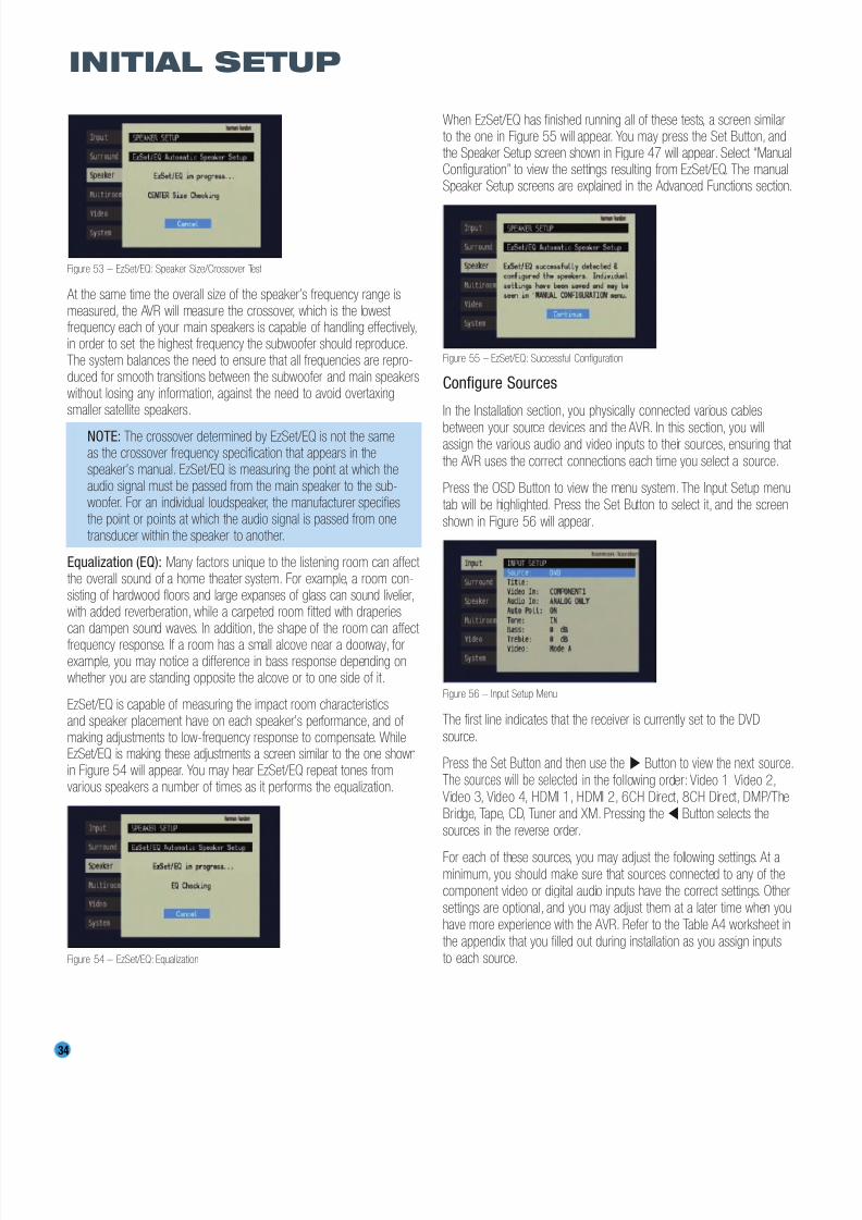
8/2/2019 AVR247om lores
http://slidepdf.com/reader/full/avr247om-lores 34/76
34
INITIAL SETUP
Figure 53 – EzSet/EQ: Speaker Size/Crossover Test
At the same time the overall size of the speaker’s frequency range ismeasured, the AVR will measure the crossover, which is the lowest frequency each of your main speakers is capable of handling effectively,in order to set the highest frequency the subwoofer should reproduce.The system balances the need to ensure that all frequencies are repro-duced for smooth transitions between the subwoofer and main speakerswithout losing any information, against the need to avoid overtaxingsmaller satellite speakers.
NOTE: The crossover determined by EzSet/EQ is not the sameas the crossover frequency specification that appears in thespeaker’s manual. EzSet/EQ is measuring the point at which theaudio signal must be passed from the main speaker to the sub-woofer. For an individual loudspeaker, the manufacturer specifiesthe point or points at which the audio signal is passed from onetransducer within the speaker to another.
Equalization (EQ): Many factors unique to the listening room can affect the overall sound of a home theater system. For example, a room con-sisting of hardwood floors and large expanses of glass can sound livelier,with added reverberation, while a carpeted room fitted with draperiescan dampen sound waves. In addition, the shape of the room can affect
frequency response. If a room has a small alcove near a doorway, forexample, you may notice a difference in bass response depending onwhether you are standing opposite the alcove or to one side of it.
EzSet/EQ is capable of measuring the impact room characteristicsand speaker placement have on each speaker’s performance, and of making adjustments to low-frequency response to compensate. WhileEzSet/EQ is making these adjustments a screen similar to the one shownin Figure 54 will appear. You may hear EzSet/EQ repeat tones fromvarious speakers a number of times as it performs the equalization.
Figure 54 – EzSet/EQ: Equalization
When EzSet/EQ has finished running all of these tests, a screen similarto the one in Figure 55 will appear. You may press the Set Button, andthe Speaker Setup screen shown in Figure 47 will appear. Select “ManualConfiguration” to view the settings resulting from EzSet/EQ. The manualSpeaker Setup screens are explained in the Advanced Functions section.
Figure 55 – EzSet/EQ: Successful Configuration
Configure Sources
In the Installation section, you physically connected various cables
between your source devices and the AVR. In this section, you willassign the various audio and video inputs to their sources, ensuring that
the AVR uses the correct connections each time you select a source.
Press the OSD Button to view the menu system. The Input Setup menutab will be highlighted. Press the Set Button to select it, and the screen
shown in Figure 56 will appear.
Figure 56 – Input Setup Menu
The first line indicates that the receiver is currently set to the DVD
source.
Press the Set Button and then use the › Button to view the next source.The sources will be selected in the following order: Video 1, Video 2,Video 3, Video 4, HDMI 1, HDMI 2, 6CH Direct, 8CH Direct, DMP/TheBridge, Tape, CD, Tuner and XM. Pressing the ‹ Button selects the
sources in the reverse order.
For each of these sources, you may adjust the following settings. At aminimum, you should make sure that sources connected to any of thecomponent video or digital audio inputs have the correct settings. Other
settings are optional, and you may adjust them at a later time when youhave more experience with the AVR. Refer to the Table A4 worksheet in
the appendix that you filled out during installation as you assign inputsto each source.
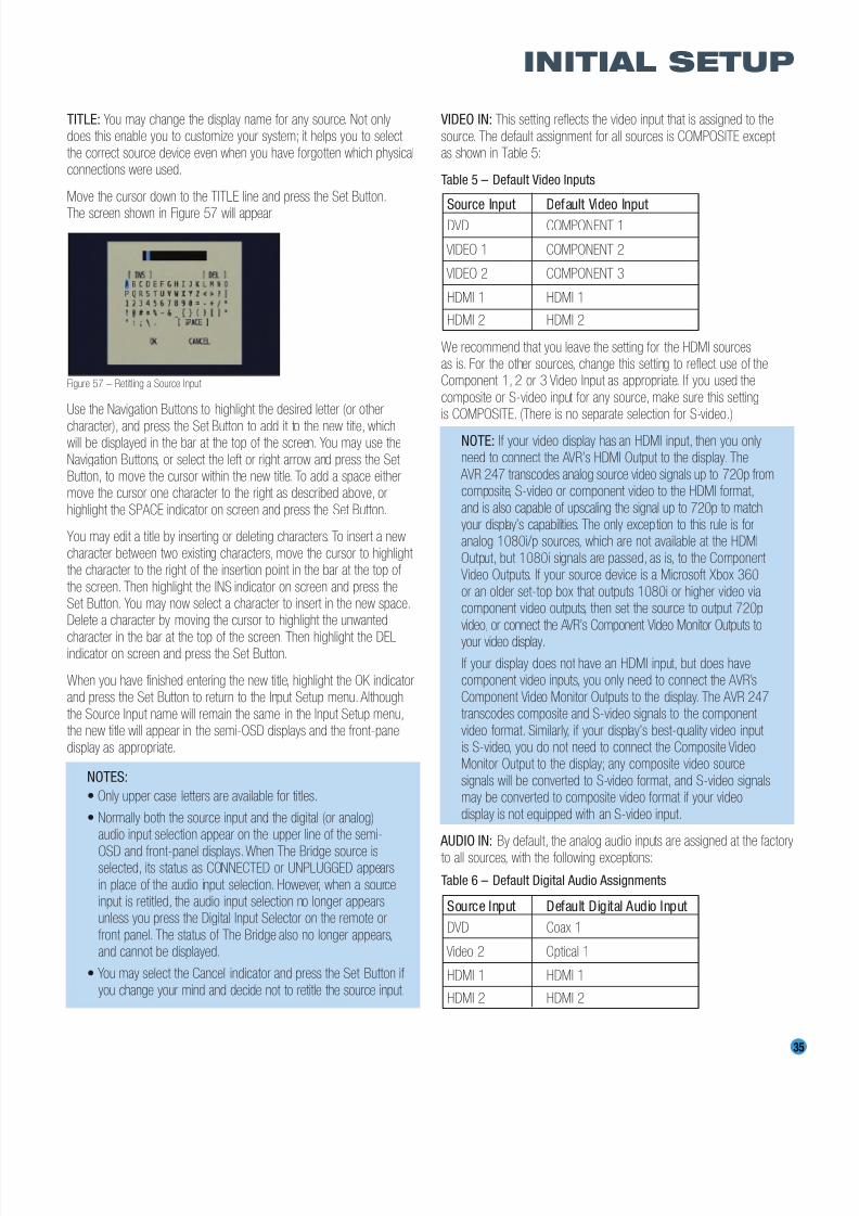
8/2/2019 AVR247om lores
http://slidepdf.com/reader/full/avr247om-lores 35/76
35
INITIAL SETUP
TITLE: You may change the display name for any source. Not onlydoes this enable you to customize your system; it helps you to select
the correct source device even when you have forgotten which physicalconnections were used.
Move the cursor down to the TITLE line and press the Set Button.
The screen shown in Figure 57 will appear.
Figure 57 – Retitling a Source Input
Use the Navigation Buttons to highlight the desired letter (or other
character), and press the Set Button to add it to the new title, whichwill be displayed in the bar at the top of the screen. You may use the
Navigation Buttons, or select the left or right arrow and press the Set Button, to move the cursor within the new title. To add a space eithermove the cursor one character to the right as described above, or
highlight the SPACE indicator on screen and press the Set Button.
You may edit a title by inserting or deleting characters. To insert a new
character between two existing characters, move the cursor to highlight the character to the right of the insertion point in the bar at the top of
the screen. Then highlight the INS indicator on screen and press theSet Button. You may now select a character to insert in the new space.Delete a character by moving the cursor to highlight the unwanted
character in the bar at the top of the screen. Then highlight the DELindicator on screen and press the Set Button.
When you have finished entering the new title, highlight the OK indicatorand press the Set Button to return to the Input Setup menu. Although
the Source Input name will remain the same in the Input Setup menu,the new title will appear in the semi-OSD displays and the front-panel
display as appropriate.
NOTES:
• Only upper case letters are available for titles.
• Normally both the source input and the digital (or analog)audio input selection appear on the upper line of the semi-
OSD and front-panel displays.When The Bridge source isselected, its status as CONNECTED or UNPLUGGED appears
in place of the audio input selection. However, when a sourceinput is retitled, the audio input selection no longer appearsunless you press the Digital Input Selector on the remote or
front panel. The status of The Bridge also no longer appears,and cannot be displayed.
• You may select the Cancel indicator and press the Set Button if
you change your mind and decide not to retitle the source input.
VIDEO IN: This setting reflects the video input that is assigned to the
source. The default assignment for all sources is COMPOSITE except as shown in Table 5:
Table 5 – Default Video Inputs
We recommend that you leave the setting for the HDMI sourcesas is. For the other sources, change this setting to reflect use of theComponent 1, 2 or 3 Video Input as appropriate. If you used the
composite or S-video input for any source, make sure this settingis COMPOSITE. (There is no separate selection for S-video.)
NOTE: If your video display has an HDMI input, then you onlyneed to connect the AVR’s HDMI Output to the display. The
AVR 247 transcodes analog source video signals up to 720p fromcomposite, S-video or component video to the HDMI format,
and is also capable of upscaling the signal up to 720p to matchyour display’s capabilities. The only exception to this rule is foranalog 1080i/p sources, which are not available at the HDMI
Output, but 1080i signals are passed, as is, to the Component Video Outputs. If your source device is a Microsoft Xbox 360
or an older set-top box that outputs 1080i or higher video viacomponent video outputs, then set the source to output 720p
video, or connect the AVR’s Component Video Monitor Outputs to
your video display.
If your display does not have an HDMI input, but does havecomponent video inputs, you only need to connect the AVR’s
Component Video Monitor Outputs to the display. The AVR 247transcodes composite and S-video signals to the component
video format. Similarly, if your display’s best-quality video input is S-video, you do not need to connect the Composite VideoMonitor Output to the display; any composite video source
signals will be converted to S-video format, and S-video signalsmay be converted to composite video format if your video
display is not equipped with an S-video input.
AUDIO IN: By default, the analog audio inputs are assigned at the factory
to all sources, with the following exceptions:
Table 6 – Default Digital Audio Assignments
Source Input Default Digital Audio Input
DVD Coax 1
Video 2 Optical 1
HDMI 1 HDMI 1
HDMI 2 HDMI 2
Source Input Default Video Input
DVD COMPONENT 1
VIDEO 1 COMPONENT 2
VIDEO 2 COMPONENT 3
HDMI 1 HDMI 1
HDMI 2 HDMI 2

8/2/2019 AVR247om lores
http://slidepdf.com/reader/full/avr247om-lores 36/76
36
INITIAL SETUP
If you used a digital audio connection for another source, change thissetting to assign the correct digital audio input to the source, even if you
also connected the analog audio outputs of the source to the receiver.
AUTO POLL: The Auto Poll feature is used when both an analog audio
and digital audio connection have been made for one source device.
If for some reason no digital signal is available, the AVR 247 will switchto the analog inputs for the source. This situation can occur with somecable or satellite television broadcasts, where some channels are broad-
cast with digital audio and others with analog audio.
For some sources, the Auto Poll feature is unnecessary and may beundesirable. For example, if your DVD player is stopped, you may not
want to use the analog audio signal or you may have decided not toconnect analog audio. Move the cursor to this line, press the Set Button
and press the ‹ / › Buttons until OFF appears, disabling the Auto Pollfeature. With Auto Poll turned off, the receiver will only check for a signal
at the audio input assigned to the source.
NOTE: Since The Bridge is connected to the AVR using adedicated audio connection, it isn’t possible to select a different
audio input for this source. The AM/FM/XM tuner and 6-/8-Channel Inputs also use dedicated audio inputs, and it isn’t
possible to select a digital audio input for these sources.
The next three lines in the Input Setup menu activate the tone controls,
and may be skipped at this time. We recommend leaving the tonecontrols at their factory defaults for most listening, in order to enjoy thesound mix created by your favorite movie and music artists. However,
if your room or speakers have unusual characteristics, or simply asa matter of personal preference, see the Tone Controls section on
page 38 for more information.
VIDEO MODE: This setting is used only with a fully analog video path(composite, S-video or component video). It has no effect on HDMIsources and video displays. Due to the design of some analog video
displays and the nature of the video standard, there may be timingissues with the AVR. If you observe some minor video instability whenusing the AVR’s analog video outputs, try changing the Video Mode
setting to Mode B. If you continue to observe problems, connect yoursource device’s video output directly to the video display, or consider
upgrading to an HDMI-capable display.
You are now ready to begin enjoying your new receiver!
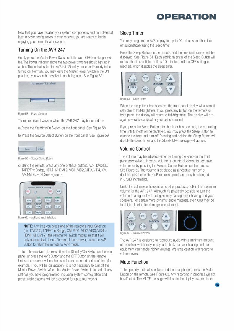
8/2/2019 AVR247om lores
http://slidepdf.com/reader/full/avr247om-lores 37/76
37
OPERATION
Now that you have installed your system components and completed at least a basic configuration of your receiver, you are ready to begin
enjoying your home theater system.
Turning On the AVR 247
Gently press the Master Power Switch until the word OFF is no longer visi-ble. The Power Indicator above the two power switches should light up in
amber. This indicates that the AVR is in Standby mode and is ready to be
turned on. Normally, you may leave the Master Power Switch in the ON
position, even when the receiver is not being used. See Figure 58.
Figure 58 – Power Switches
There are several ways in which the AVR 247 may be turned on:
a) Press the Standby/On Switch on the front panel. See Figure 58.
b) Press the Source Select Button on the front panel. See Figure 59.
Figure 59 – Source Select Button
c) Using the remote, press any one of these buttons: AVR, DVD/CD,
TAPE/The Bridge, HDMI 1/HDMI 2, VID1, VID2, VID3, VID4, XM,
AM/FM, 6/8CH. See Figure 60.
Figure 60 – AVR and Input Selectors
NOTE: Any time you press one of the remote’s Input Selectors
(i.e., DVD/CD, TAPE/The Bridge, XM, VID1, VID2, VID3, VID4 orHDMI 1/HDMI 2), the remote will switch modes so that it willonly operate that device. To control the receiver, press the AVR
Button to return the remote to AVR mode.
To turn the receiver off, press either the Standby/On Switch on the front
panel, or press the AVR Button and the OFF Button on the remote.Unless the receiver will not be used for an extended period of time (forexample, if you will be on vacation), it is not necessary to turn off the
Master Power Switch. When the Master Power Switch is turned off, anysettings you have programmed, including system configuration and
preset radio stations, will be preserved for up to four weeks.
Sleep Timer
You may program the AVR to play for up to 90 minutes and then turnoff automatically using the sleep timer.
Press the Sleep Button on the remote, and the time until turn-off will be
displayed. See Figure 61. Each additional press of the Sleep Button willreduce the time until turn-off by 10 minutes, until the OFF setting isreached, which disables the sleep timer.
Figure 61 – Sleep Button
When the sleep timer has been set, the front-panel display will automati-
cally dim to half-brightness. If you press any button on the remote or
front panel, the display will return to full-brightness. The display will dimagain several seconds after your last command.
If you press the Sleep Button after the timer has been set, the remaining
time until turn-off will be displayed. You may press the Sleep Button tochange the time until turn-off. Pressing and holding the Sleep Button willdisable the sleep timer, and the SLEEP OFF message will appear.
Volume Control
The volume may be adjusted either by turning the knob on the front panel (clockwise to increase volume or counterclockwise to decrease
volume), or by pressing the Volume Control Buttons on the remote.See Figure 62. The volume is displayed as a negative number of
decibels (dB) below the 0dB reference point, and may be changedin 0.5dB increments.
Unlike the volume controls on some other products, 0dB is the maximumvolume for the AVR 247. Although it’s physically possible to turn thevolume to a higher level, doing so may damage your hearing and your
speakers. For certain more dynamic audio materials, even 0dB may betoo high, allowing for damage to equipment.
Figure 62 – Volume Controls
The AVR 247 is designed to reproduce audio with a minimum amount of distortion, which may lead you to think that your hearing and theequipment can handle higher volumes. We urge caution with regard to
volume levels.
Mute Function
To temporarily mute all speakers and the headphones, press the Mute
Button on the remote. See Figure 63. Any recording in progress will not be affected. The MUTE message will flash in the display as a reminder.
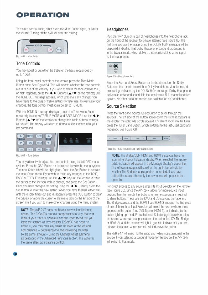
8/2/2019 AVR247om lores
http://slidepdf.com/reader/full/avr247om-lores 38/76
38
OPERATION
To restore normal audio, either press the Mute Button again, or adjust the volume. Turning off the AVR will also end muting.
Figure 63 – Mute Button
Tone Controls
You may boost or cut either the treble or the bass frequencies byup to 10dB.
Using the front-panel controls or the remote, press the Tone ModeButton once. See Figure 64. This will indicate whether the tone controls
are in or out of the circuitry. If you wish to return the tone controls to 0,or “flat” response, press the ‹ / › Buttons (⁄ / ¤ on the remote) until
the TONE OUT message appears, which preserves any changes youhave made to the bass or treble settings for later use. To reactivate yourchanges, the tone control must again be set to TONE IN.
With the TONE IN message displayed, press the Tone Mode Buttonrepeatedly to access TREBLE MODE and BASS MODE. Use the ‹ / ›
Buttons (⁄ / ¤ on the remote) to change the treble or bass settings,as desired. The display will return to normal a few seconds after your
last command.
Figure 64 – Tone Button
You may alternatively adjust the tone controls using the full-OSD menu
system. Press the OSD Button on the remote to view the menu system.The Input Setup tab will be highlighted. Press the Set Button to activate
the Input Setup menu. If you wish to make any changes to the TONE,BASS or TREBLE settings, use the⁄ / ¤ keys on the remote to move
the cursor to the line you wish to change, and press the Set Button.Once you have changed the setting using the ‹ / › Buttons, press theSet Button to enter the new setting. When you have finished, either wait
until the display times out and disappears, press the OSD Button to clearthe display, or move the cursor to the menu tabs on the left side of the
screen line if you wish to make other changes using the menu system.
NOTE: The AVR 247 does not have a conventional balance
control. The EzSet/EQ process compensates for any character-istics of your room or speakers, and we recommend that you
leave the settings as they are after EzSet/EQ has been run.However, you may manually adjust the levels of the left andright channels – decreasing one and increasing the other
by the same amount – using the Channel Adjust submenu,as described in the Advanced Functions section. This achieves
the same effect as a balance control.
Headphones
Plug the 1/4" plug on a pair of headphones into the headphone jack on the front of the receiver for private listening. See Figure 65. The
first time you use the headphones, the DOLBY H:BP message will bedisplayed, indicating that Dolby Headphone surround processing is
in the bypass mode, which delivers a conventional 2-channel signalto the headphones.
Figure 65 – Headphone Jack
Press the Surround Select Button on the front panel, or the Dolby
Button on the remote, to switch to Dolby Headphone virtual surroundprocessing, indicated by the DOLBY H:DH message. Dolby Headphone
delivers an enhanced sound field that emulates a 5.1-channel speakersystem. No other surround modes are available for the headphones.
Source Selection
Press the front-panel Source Select Button to scroll through thesources. The left side of the button scrolls down the list that appears inthe display; the right side scrolls upward. For direct access to the tuner,
press the Tuner Band Button, which switches to the last-used band andfrequency. See Figure 66.
Figure 66 – Source Select and Tuner Band Buttons
NOTE: The Bridge/DMP, HDMI and HDMI 2 sources have noicon in the Source Indicators display. When selected, the appro-
priate indication will appear in the Message Display’s upper line.One of two messages will scroll on the right side to indicatewhether The Bridge is unplugged or connected. If you have
retitled this source, then only the new name will appear in theupper line.
For direct access to any source, press its Input Selector on the remote(see Figure 60). Since the AVR 247 allows for more source input
devices than the remote has buttons for, some sources are requiredto share buttons. These are the DVD and CD sources, the Tape and
The Bridge sources, and the HDMI 1 and HDMI 2 sources. The first press
of any of these three Input Selectors will select the source whose nameappears on the button (i.e., DVD, Tape or HDMI 1), as indicated by the
button lighting up in red. Press that Input Selector again quickly to select the source whose name appears above the button (i.e., CD, The Bridge
or HDMI 2), and the selector will light in green to indicate that you haveselected the source whose name is printed above the button.
The AVR 247 will switch to the audio and video inputs assigned to thesource. If you selected a surround mode for the source, the AVR 247will switch to that mode.

8/2/2019 AVR247om lores
http://slidepdf.com/reader/full/avr247om-lores 39/76
39
OPERATION
The source name will appear in the upper line of the front-panel display.If you retitled the source, only the new title will appear. Otherwise, the
audio input assigned to the source (analog or one of the digital audioinputs) will also appear. The surround mode will be displayed on the
lower line. The same information will also appear on screen in thesemi-OSD, unless you have set the semi-OSD to OFF in the System
Setup menu, as described in the Advanced Functions section.
Audio Input Selection
The AVR 247 is programmed at the factory to use the analog audioinputs for each source (except for the DVD, Video 2, HDMI 1 and
HDMI 2 sources; see Table 6). To assign a digital audio input to asource (if you have not done so using the Input Setup menu during
Initial Setup), press the Digital Button on the remote or front panel. Thecurrent audio input selection will flash in the display, and you may press
the⁄ / ¤ (or ‹ / › on the front panel) Buttons to scroll through theaudio inputs. When the desired input appears, press the Set Button toselect it. See Figure 67.
Figure 67 – Digital Input Selection
If the Auto Poll feature is ON in the Input Setup menu, and if a digital
audio input has been assigned to the source, the AVR 247 will first check the digital audio input for a signal. If a signal is present, the
AVR 247 will select the digital audio input. If no signal is present,
the AVR 247 will switch to the analog audio inputs for the source.
Video Input Selection
When a source is selected, the AVR 247 switches to a video input
as follows:
The VIDEO IN line of the Input Setup menu indicates which of the video
inputs on the AVR 247 is assigned to each source. As shown in Table 5,by default the Component Video 1 input is assigned to the DVD source,the Component Video 2 input is assigned to the Video 1 source, and the
Component Video 3 input is assigned to the Video 2 source. The twoHDMI inputs obtain the video signal from their own inputs, and may not
be reassigned to another video input.
If your iPod is capable of playing still images and videos, it may be used
as a video source. However, you may not select another device for viewingwhile listening to audio files stored on the iPod, nor can you view video or
images stored on the iPod while listening to another audio source.
All other sources default to the COMPOSITE setting, meaning that theyare using their composite or S-video inputs. The AVR 247 will transcode
the incoming composite or S-video signal and make it available usingthe HDMI or Component Video Monitor Outputs, enabling a single-cable
connection to your television.
NOTES:
• Due to copy-protection restrictions, there is no output at theComponent Video Monitor Outputs for copy-protected sources.
• High-resolution 1080i and 1080p video signals are not avail-able at the HDMI Output, but 1080i signals are passed through,
as is, to the Component Video Monitor Outputs. If your sourceoutputs analog high-resolution video, either use the Component Video Outputs, change the output resolution of your sourcedevice to 720p, or connect your source’s component videooutputs directly to your video display.
• Due to the design of some video displays, analog 480p or720p component video source signals may produce artifactswhen used with the AVR’s analog video outputs (composite,S-video or component video). If this occurs, try changing theVideo Mode setting in the INPUT SETUP menu, or connectingthe source device’s video output directly to your video display.However, for best results, we recommend that you considerupgrading to an HDMI-capable video display.
• The AVR 247 cannot convert 1080i or 1080p analog videosignals to the HDMI format, but passes 1080i signals to theComponent Video Outputs. This affects users of Microsoft Xbox 360 systems and some older set-top boxes. If yourdigital cable television set-top box outputs 1080i or highervideo via component video outputs and is not equipped withan HDMI output, contact your cable operator for a replace-ment. For Xbox 360 or satellite receivers with no HDMI output,change the settings on your source device so that it outputsonly 720p video through its component video outputs, whichthe AVR can convert to the HDMI format, or connect the AVR’sComponent Video Outputs to the TV. Although you could con-nect the source device’s component video outputs directly to
your video display, you would then have to select the correct video input on the display to match the AVR’s input.
The component video inputs may be reassigned to other source inputsas needed, depending on the physical connections you made during theInstallation procedure.
If a signal is present at the component video input assigned to that source, it will be selected.
If no signal is present at the component video input, then the S-video orcomposite video input for the source will be selected. It is not possibleto reassign the S-video or composite video inputs to other sources.
For audio-only sources, such as the tuner or CD inputs, when no compo-nent video signal is present, the last-used video source will be selected.
6-/8-Channel Direct Inputs
If you wish to hear audio through the 6-/8-Channel Direct Inputs togetherwith video, then connect your multichannel player to the Component Video 1 Inputs, and connect the player’s 6- or 8-channel analog audiooutputs to the 6-/8-Channel Inputs on the AVR. Assign the component video inputs you selected to the 6-/8-Channel Input source. The AVRwill automatically select the correct component video and audio inputswhen you select this source.

8/2/2019 AVR247om lores
http://slidepdf.com/reader/full/avr247om-lores 40/76
40
OPERATION
If you need to use composite or S-video for your multichannel player,e.g., if your video display does not have component video inputs, then
use the video inputs for another source. Since the AVR automaticallyselects the last-used video inputs for audio sources, first select the
source you connected the video cables to, and then the 6-/8-ChannelInputs for the audio.
Example 1: You would like to connect a DVD-Audio player to the AVR 247. You plan on playing a variety of discs using this player,
including conventional DVDs and even CDs as well as multichanneldiscs. When playing DVDs and CDs, it is preferable to use a digital audioconnection to obtain the best sound quality and the benefit of any digital
surround formats contained on the DVD. However, when playing DVD- Audio discs, you will need to use the 6-/8-channel analog audio
connections. In addition, some of these discs contain video materials.The player does not have an HDMI output.
We recommend that you connect this player as follows:
a) Connect the player’s coaxial digital audio output to the Coaxial 1 input on the AVR. This input is assigned by default to the DVD source.
b) Connect the player’s component video outputs to the Component Video 1 inputs on the AVR, which are assigned by default to the DVD
source. If your video display doesn’t have component video inputs,then connect the player’s composite or S-video output to the DVD’s
corresponding video input.
c) Connect the player’s 6-channel analog audio outputs to the AVR’s
6-/8-Channel Inputs and assign the Component Video 1 inputs tothis source using the Input Setup menu, as described in the InitialSetup section.
d) Program the player’s remote control codes into the DVD Input Selector. Note that not all commands will necessarily be available.
When you wish to view a DVD, simply select the DVD source.
When you wish to listen to a DVD-Audio disc and view the menus
and other still images on the disc, first select DVD, and then the6-/8-Channel Inputs as the source.
Example 2: In this example, your multichannel disc player is equippedwith an HDMI output, but it does not comply with HDMI version 1.1.
Connect it as follows:
a) Connect the player’s HDMI output to the HDMI 1 source input, andmake sure to connect the AVR’s HDMI Output to your video display.
The player will transmit both digital audio (e.g., Dolby Digital or DTSaudio found on a DVD-Video disc) and video via the HDMI connection.
It is not necessary to make a separate digital audio connection.
b) Connect the player’s 6-channel analog audio outputs to the AVR’s
6-/8-Channel Inputs, and connect one of the player’s analog videooutputs to a source input on the AVR (e.g., Component Video 3 or
Video 3).
c) Program the player’s remote control codes into the Input Selectorcorresponding to the source you used for the analog video connection,
e.g., Video 3.
When you wish to view a DVD, simply select the HDMI 1 source.
When you wish to play a multichannel disc, first select the analog videosource, e.g., Video 3, to obtain the correct video signal, then select the6-/8-Channel Inputs to select the audio signal.
To select the 6-/8-Channel Inputs as the source, use either the SourceSelector on the front panel or press the 6/8CH Input Selector on the
remote. See Figure 68.
Figure 68 – 6-/8-Channel Input Selector
NOTE: The 6-/8-Channel Inputs pass the incoming signals
directly to the volume control, without digitizing or processingthem. Therefore, you will need to configure bass management settings (i.e., speaker size, delay and output level) on your source
device so that they match the settings you programmed usingEzSet/EQ, which may be viewed using the Manual Setup menu
(see Advanced Functions section). Consult the owner’s guide foryour multichannel player for more information.
The multichannel analog audio connection is not required for DVD-Audioplayers compliant with HDMI version 1.1 or better, or HD-DVD and
Blu-ray Disc players that decode the digital audio internally and output linear PCM signals in digital format. Consult the owner’s guide for yourdisc player for more information.
Using the Tuner
The AVR 247’s built-in tuner may be selected in one of three ways
(see Figure 69):
1. Press the Source Selector Button on the front panel repeatedly until
the tuner is selected. The last-used band (AM or FM) will be active.
2. Press the Tuner Band Button (marked AM/FM). Press this button
again to switch bands. This will also enable you to select XM Radio,which is described separately in the next section.
3. Press the Tuner Input Selector (marked AM/FM) on the remote. Pressthis button again to switch bands (AM, FM or XM).
Figure 69 – Tuner Input Selection
Radio stations may be selected in one of four ways (see Figure 70):
1. If you know the frequency number, enter it directly by first pressing
the Direct Button on the remote, and then using the Numeric Keys.
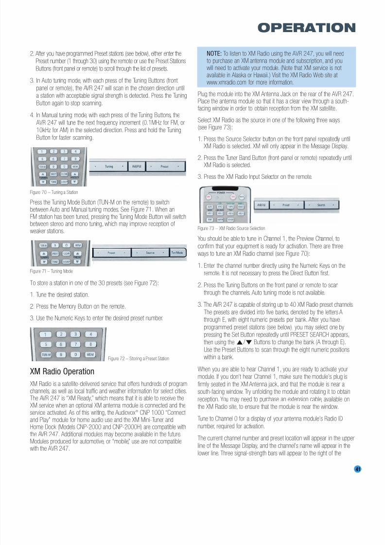
8/2/2019 AVR247om lores
http://slidepdf.com/reader/full/avr247om-lores 41/76
41
OPERATION
2. After you have programmed Preset stations (see below), either enter thePreset number (1 through 30) using the remote or use the Preset Stations
Buttons (front panel or remote) to scroll through the list of presets.
3. In Auto tuning mode, with each press of the Tuning Buttons (front
panel or remote), the AVR 247 will scan in the chosen direction until
a station with acceptable signal strength is detected. Press the TuningButton again to stop scanning.
4. In Manual tuning mode, with each press of the Tuning Buttons, the
AVR 247 will tune the next frequency increment (0.1MHz for FM, or10kHz for AM) in the selected direction. Press and hold the TuningButton for faster scanning.
Figure 70 – Tuning a Station
Press the Tuning Mode Button (TUN-M on the remote) to switchbetween Auto and Manual tuning modes. See Figure 71. When anFM station has been tuned, pressing the Tuning Mode Button will switchbetween stereo and mono tuning, which may improve reception of weaker stations.
Figure 71 – Tuning Mode
To store a station in one of the 30 presets (see Figure 72):
1. Tune the desired station.
2. Press the Memory Button on the remote.
3. Use the Numeric Keys to enter the desired preset number.
Figure 72 – Storing a Preset Station
XM Radio Operation
XM Radio is a satellite-delivered service that offers hundreds of programchannels, as well as local traffic and weather information for select cities.The AVR 247 is “XM Ready,” which means that it is able to receive theXM service when an optional XM antenna module is connected and theservice activated. As of this writing, the Audiovox® CNP 1000 “Connect and Play” module for home audio use and the XM Mini-Tuner andHome Dock (Models CNP-2000 and CNP-2000H) are compatible withthe AVR 247. Additional modules may become available in the future.Modules produced for automotive, or “mobile,” use are not compatiblewith the AVR 247.
NOTE: To listen to XM Radio using the AVR 247, you will needto purchase an XM antenna module and subscription, and youwill need to activate your module. (Note that XM service is not available in Alaska or Hawaii.) Visit the XM Radio Web site at www.xmradio.com for more information.
Plug the module into the XM Antenna Jack on the rear of the AVR 247.Place the antenna module so that it has a clear view through a south-facing window in order to obtain reception from the XM satellite.
Select XM Radio as the source in one of the following three ways(see Figure 73):
1. Press the Source Selector button on the front panel repeatedly untilXM Radio is selected. XM will only appear in the Message Display.
2. Press the Tuner Band Button (front-panel or remote) repeatedly untilXM Radio is selected.
3. Press the XM Radio Input Selector on the remote.
Figure 73 – XM Radio Source Selection
You should be able to tune in Channel 1, the Preview Channel, to
confirm that your equipment is ready for activation. There are threeways to tune an XM Radio channel (see Figure 70):
1. Enter the channel number directly using the Numeric Keys on theremote. It is not necessary to press the Direct Button first.
2. Press the Tuning Buttons on the front panel or remote to scanthrough the channels. Auto tuning mode is not available.
3. The AVR 247 is capable of storing up to 40 XM Radio preset channels.
The presets are divided into five banks, denoted by the letters Athrough E, with eight numeric presets per bank. After you have
programmed preset stations (see below), you may select one bypressing the Set Button repeatedly until PRESET SEARCH appears,
then using the ⁄ / ¤ Buttons to change the bank (A through E).
Use the Preset Buttons to scan through the eight numeric positionswithin a bank.
When you are able to hear Channel 1, you are ready to activate yourmodule. If you don’t hear Channel 1, make sure the module’s plug is
firmly seated in the XM Antenna jack, and that the module is near asouth-facing window. Try unfolding the module and rotating it to obtain
reception. You may need to purchase an extension cable, available onthe XM Radio site, to ensure that the module is near the window.
Tune to Channel 0 for a display of your antenna module’s Radio ID
number, required for activation.
The current channel number and preset location will appear in the upper
line of the Message Display, and the channel’s name will appear in thelower line. Three signal-strength bars will appear to the right of the
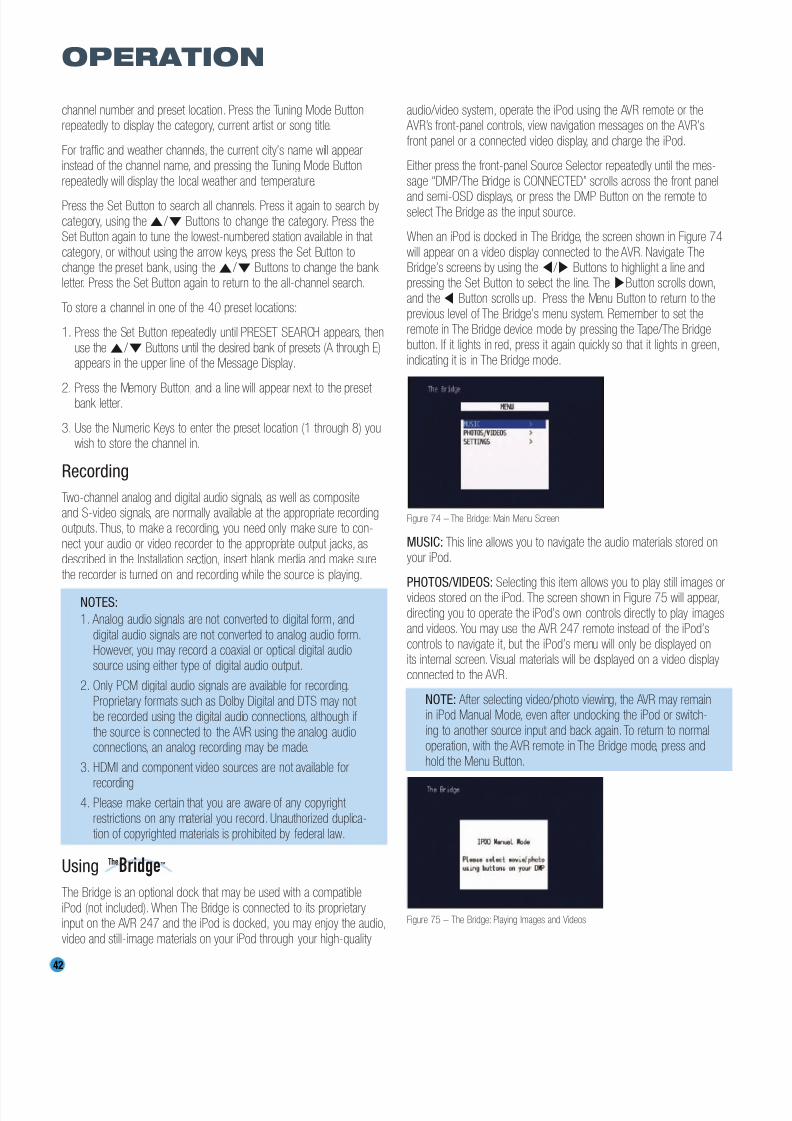
8/2/2019 AVR247om lores
http://slidepdf.com/reader/full/avr247om-lores 42/76
42
OPERATION
channel number and preset location. Press the Tuning Mode Buttonrepeatedly to display the category, current artist or song title.
For traffic and weather channels, the current city’s name will appearinstead of the channel name, and pressing the Tuning Mode Button
repeatedly will display the local weather and temperature.
Press the Set Button to search all channels. Press it again to search by
category, using the⁄ / ¤ Buttons to change the category. Press theSet Button again to tune the lowest-numbered station available in that
category, or without using the arrow keys, press the Set Button tochange the preset bank, using the⁄ / ¤ Buttons to change the bank letter. Press the Set Button again to return to the all-channel search.
To store a channel in one of the 40 preset locations:
1. Press the Set Button repeatedly until PRESET SEARCH appears, then
use the⁄ / ¤ Buttons until the desired bank of presets (A through E)appears in the upper line of the Message Display.
2. Press the Memory Button, and a line will appear next to the preset bank letter.
3. Use the Numeric Keys to enter the preset location (1 through 8) youwish to store the channel in.
Recording
Two-channel analog and digital audio signals, as well as compositeand S-video signals, are normally available at the appropriate recordingoutputs. Thus, to make a recording, you need only make sure to con-
nect your audio or video recorder to the appropriate output jacks, asdescribed in the Installation section, insert blank media and make sure
the recorder is turned on and recording while the source is playing.
NOTES:
1. Analog audio signals are not converted to digital form, and
digital audio signals are not converted to analog audio form.However, you may record a coaxial or optical digital audiosource using either type of digital audio output.
2. Only PCM digital audio signals are available for recording.
Proprietary formats such as Dolby Digital and DTS may not be recorded using the digital audio connections, although if
the source is connected to the AVR using the analog audioconnections, an analog recording may be made.
3. HDMI and component video sources are not available for
recording.4. Please make certain that you are aware of any copyright
restrictions on any material you record. Unauthorized duplica-tion of copyrighted materials is prohibited by federal law.
Using
The Bridge is an optional dock that may be used with a compatible
iPod (not included). When The Bridge is connected to its proprietaryinput on the AVR 247 and the iPod is docked, you may enjoy the audio,
video and still-image materials on your iPod through your high-quality
audio/video system, operate the iPod using the AVR remote or the AVR’s front-panel controls, view navigation messages on the AVR’s
front panel or a connected video display, and charge the iPod.
Either press the front-panel Source Selector repeatedly until the mes-
sage “DMP/The Bridge is CONNECTED” scrolls across the front panel
and semi-OSD displays, or press the DMP Button on the remote toselect The Bridge as the input source.
When an iPod is docked in The Bridge, the screen shown in Figure 74
will appear on a video display connected to the AVR. Navigate TheBridge’s screens by using the ‹ / › Buttons to highlight a line andpressing the Set Button to select the line. The ›Button scrolls down,
and the ‹ Button scrolls up. Press the Menu Button to return to theprevious level of The Bridge’s menu system. Remember to set the
remote in The Bridge device mode by pressing the Tape/The Bridgebutton. If it lights in red, press it again quickly so that it lights in green,
indicating it is in The Bridge mode.
Figure 74 – The Bridge: Main Menu Screen
MUSIC: This line allows you to navigate the audio materials stored onyour iPod.
PHOTOS/VIDEOS: Selecting this item allows you to play still images orvideos stored on the iPod. The screen shown in Figure 75 will appear,
directing you to operate the iPod’s own controls directly to play imagesand videos. You may use the AVR 247 remote instead of the iPod’s
controls to navigate it, but the iPod’s menu will only be displayed onits internal screen. Visual materials will be displayed on a video displayconnected to the AVR.
NOTE: After selecting video/photo viewing, the AVR may remainin iPod Manual Mode, even after undocking the iPod or switch-
ing to another source input and back again. To return to normaloperation, with the AVR remote in The Bridge mode, press and
hold the Menu Button.
Figure 75 – The Bridge: Playing Images and Videos
TheBridgeTM
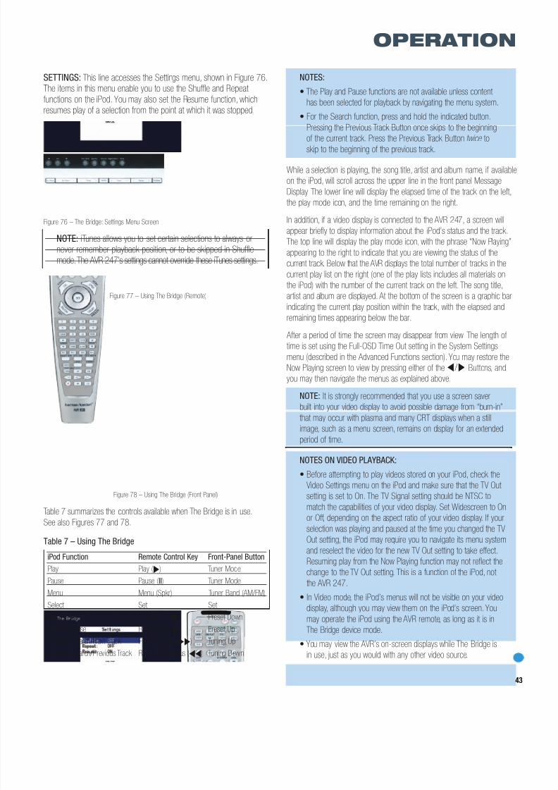
8/2/2019 AVR247om lores
http://slidepdf.com/reader/full/avr247om-lores 43/76
43
OPERATION
SETTINGS: This line accesses the Settings menu, shown in Figure 76.The items in this menu enable you to use the Shuffle and Repeat
functions on the iPod. You may also set the Resume function, whichresumes play of a selection from the point at which it was stopped,
Figure 76 – The Bridge: Settings Menu Screen
NOTE: iTunes allows you to set certain selections to always ornever remember playback position, or to be skipped in Shuffle
mode.The AVR 247’s settings cannot override these iTunes settings.
Figure 77 – Using The Bridge (Remote)
Figure 78 – Using The Bridge (Front Panel)
Table 7 summarizes the controls available when The Bridge is in use.
See also Figures 77 and 78.
Table 7 – Using The Bridge
NOTES:
• The Play and Pause functions are not available unless content
has been selected for playback by navigating the menu system.
• For the Search function, press and hold the indicated button.
Pressing the Previous Track Button once skips to the beginning
of the current track. Press the Previous Track Button twice toskip to the beginning of the previous track.
While a selection is playing, the song title, artist and album name, if available
on the iPod, will scroll across the upper line in the front panel Message
Display. The lower line will display the elapsed time of the track on the left,
the play mode icon, and the time remaining on the right.
In addition, if a video display is connected to the AVR 247, a screen will
appear briefly to display information about the iPod’s status and the track.
The top line will display the play mode icon, with the phrase “Now Playing”
appearing to the right to indicate that you are viewing the status of the
current track. Below that the AVR displays the total number of tracks in the
current play list on the right (one of the play lists includes all materials onthe iPod) with the number of the current track on the left. The song title,
artist and album are displayed. At the bottom of the screen is a graphic bar
indicating the current play position within the track, with the elapsed and
remaining times appearing below the bar.
After a period of time the screen may disappear from view. The length of
time is set using the Full-OSD Time Out setting in the System Settings
menu (described in the Advanced Functions section). You may restore the
Now Playing screen to view by pressing either of the ‹ / › Buttons, and
you may then navigate the menus as explained above.
NOTE: It is strongly recommended that you use a screen saver
built into your video display to avoid possible damage from “burn-in”
that may occur with plasma and many CRT displays when a stillimage, such as a menu screen, remains on display for an extended
period of time.
NOTES ON VIDEO PLAYBACK:
• Before attempting to play videos stored on your iPod, check the
Video Settings menu on the iPod and make sure that the TV Out
setting is set to On. The TV Signal setting should be NTSC to
match the capabilities of your video display. Set Widescreen to On
or Off, depending on the aspect ratio of your video display. If your
selection was playing and paused at the time you changed the TV
Out setting, the iPod may require you to navigate its menu system
and reselect the video for the new TV Out setting to take effect.Resuming play from the Now Playing function may not reflect the
change to the TV Out setting. This is a function of the iPod, not
the AVR 247.
• In Video mode, the iPod’s menus will not be visible on your video
display, although you may view them on the iPod’s screen. You
may operate the iPod using the AVR remote, as long as it is in
The Bridge device mode.
• You may view the AVR’s on-screen displays while The Bridge is
in use, just as you would with any other video source.
iPod Function Remote Control Key Front-Panel Button
Play Play (›) Tuner Mode
Pause Pause (II) Tuner Mode
Menu Menu (Spkr) Tuner Band (AM/FM)
Select Set Set
Scroll Forward Left Arrow (‹) Preset Down
Scroll Reverse Right Arrow (›) Preset Up
Forward Search/Next Track Forward/Next (››) Tuning Up
Reverse Search/Previous Track Reverse/Previous (‹‹) Tuning Down
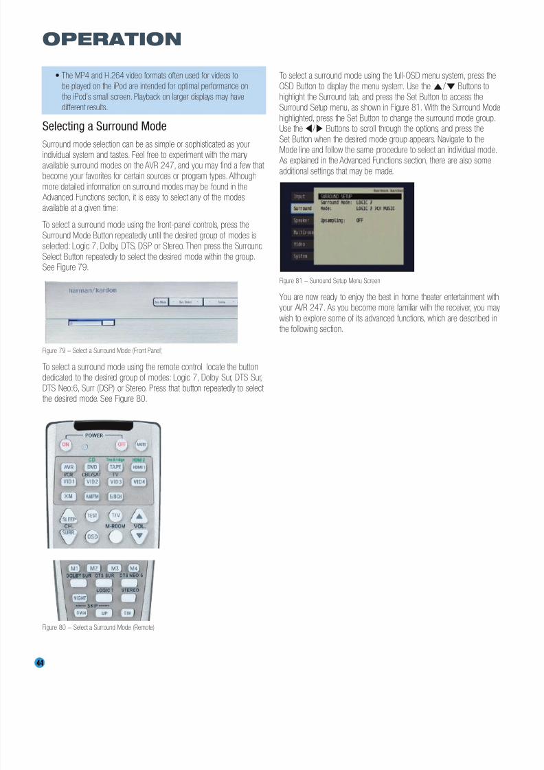
8/2/2019 AVR247om lores
http://slidepdf.com/reader/full/avr247om-lores 44/76
44
OPERATION
• The MP4 and H.264 video formats often used for videos to
be played on the iPod are intended for optimal performance on
the iPod’s small screen. Playback on larger displays may have
different results.
Selecting a Surround Mode
Surround mode selection can be as simple or sophisticated as your
individual system and tastes. Feel free to experiment with the manyavailable surround modes on the AVR 247, and you may find a few that become your favorites for certain sources or program types. Although
more detailed information on surround modes may be found in the Advanced Functions section, it is easy to select any of the modes
available at a given time:
To select a surround mode using the front-panel controls, press the
Surround Mode Button repeatedly until the desired group of modes isselected: Logic 7, Dolby, DTS, DSP or Stereo. Then press the Surround
Select Button repeatedly to select the desired mode within the group.
See Figure 79.
Figure 79 – Select a Surround Mode (Front Panel)
To select a surround mode using the remote control, locate the buttondedicated to the desired group of modes: Logic 7, Dolby Sur, DTS Sur,
DTS Neo:6, Surr (DSP) or Stereo. Press that button repeatedly to select the desired mode. See Figure 80.
Figure 80 – Select a Surround Mode (Remote)
To select a surround mode using the full-OSD menu system, press theOSD Button to display the menu system. Use the⁄ / ¤ Buttons to
highlight the Surround tab, and press the Set Button to access theSurround Setup menu, as shown in Figure 81. With the Surround Mode
highlighted, press the Set Button to change the surround mode group.Use the ‹ / › Buttons to scroll through the options, and press the
Set Button when the desired mode group appears. Navigate to theMode line and follow the same procedure to select an individual mode.
As explained in the Advanced Functions section, there are also some
additional settings that may be made.
Figure 81 – Surround Setup Menu Screen
You are now ready to enjoy the best in home theater entertainment withyour AVR 247. As you become more familiar with the receiver, you may
wish to explore some of its advanced functions, which are described inthe following section.
8/2/2019 AVR247om lores
http://slidepdf.com/reader/full/avr247om-lores 45/76
45
ADVANCED FUNCTIONS
Much of the AVR 247’s performance is handled automatically, with littleintervention required on your part. However, the AVR 247 is a sophisti-
cated component, and is capable of being customized to suit yourparticular system and your tastes. In this section we describe some of
the more advanced adjustments available on the AVR 247. You mayreturn to this section later, when you have become more familiar with
your receiver.
Audio Processing and Surround Sound
Audio signals output by sources are encoded in a variety of formats that can affect not only the quality of the sound but the number of speaker
channels and the surround mode. You may also manually select adifferent surround mode, although for certain types of audio signals,
the modes available will be limited in certain ways, as described below.
Analog Audio Signals
Analog audio signals usually consist of two channels – left and right.
The AVR 247 offers three basic options for playback of analog audio:1. Analog Bypass Mode: In this mode, the 2-channel signal is passed
directly to the volume control, without being digitized or undergoingany processing for bass management or surround sound. Therequirements for selecting analog bypass mode are:
a) The analog audio inputs for the source must be selected. If neces-sary, press the Digital Button on the remote and use the⁄ / ¤
Buttons to make the selection.
b) The tone controls must be disabled by setting TONE MODE to OUT.
Either use the Input Setup menu in the full-OSD system to makethis change, or press the Tone Mode Button on the front panel or
remote and use the ‹ / › Buttons (⁄ / ¤ on the remote) untilthe TONE OUT message appears.
c) The Surround Off mode must be selected. The easiest way to
select the Surround Off mode is to press the Stereo Button on theremote until the Surround Off icon is lit (and the DSP icon is not lit)
in the front-panel display.
2. DSP Surround Off Mode: The DSP Surround Off mode digitizes the
incoming signal and applies the bass management settings, includingspeaker configuration, delay times and output levels. This mode is
desirable when your front speakers are small, limited-range satellitesand you are using a subwoofer. Both the DSP and Surround Off iconswill be lit when this mode is active. Press the Stereo Button on the
remote repeatedly to select this mode.
3. Analog Surround Modes: One of the main benefits of a surround
receiver such as the AVR 247 is its ability to process 2-channelaudio signals to produce multichannel surround sound in a variety
of modes, even when no surround sound has been encoded in therecording. Among the available modes are the Dolby Pro Logic II/IIxmodes, the Dolby Virtual Speaker modes, the DTS Neo:6 modes, the
Logic 7 modes, the Hall and Theater modes and the Stereo modes.
Digital Audio Signals
Digital audio signals offer the benefit of greater capacity, which allows
recording artists to encode center and surround channel informationdirectly into the signal. The result is improved sound quality and startling
directionality, since each of these channels is reproduced discretely.
Alternatively, the artist may encode only two channels, but the digital
signal allows for a higher sampling rate that delivers greater detail.High-resolution recordings usually sound extraordinarily distortion-freeat all frequencies, but especially at high frequencies.
Multichannel digital recordings usually are found in the 5.1-, 6.1- or7.1-channel formats. The channels included in a 5.1-channel recording
are front left, front right, center, surround left, surround right and LFE.The LFE channel is denoted as “.1” to represent the fact that it is not
full-range, being limited to the low frequencies.
6.1-Channel recordings add a single surround back channel, and
7.1-channel recordings add surround back left and surround back
right channels to the 5.1-channel configuration. New formats, such asDolby TrueHD and Dolby Digital Plus, may be available in 7.1-channel
configurations in the future. The AVR 247 will not be able to play native7.1-channel programs unless the source device outputs a 5.1- or
6.1-channel version.
NOTE: In order to use the 6.1- and 7.1-channel surround
modes, e.g., Logic 7 7-channel Cinema, the AVR 247 must beconfigured so that the Surround Back channels are enabled.See the Manual Setup section on page 51 of the Advanced
Functions section for more information.
Digital formats include Dolby Digital 2.0 (two channels only), Dolby
Digital 5.1, Dolby Digital EX, DTS 5.1, DTS-ES (6.1 Matrix andDiscrete), DTS 96/24 and 2-channel PCM modes in 32kHz, 44.1kHz,
48kHz or 96kHz.
When a digital signal is received, the AVR 247 detects the encoding
method and the number of channels. The appropriate icon will light inthe front panel for Dolby Digital and DTS signals. The number of channelsencoded will scroll once across the front-panel display as three numbers,
separated by slashes (e.g., “3/2/.1”).
The first number indicates the number of front channels in the signal:
“1” represents a monophonic recording, usually an older program that has been digitally remastered or, more rarely, a modern program
for which the director has chosen a special effect.“2” indicates the presence of the left and right channels, but no
center channel.
“3” indicates that all three front channels (left, right and center) arepresent.
The second number indicates whether any surround channels are present:
“0” indicates that no surround information is present.
“1” indicates that a matrixed surround signal is present.
“2” indicates discrete left and right surround channels.

8/2/2019 AVR247om lores
http://slidepdf.com/reader/full/avr247om-lores 46/76
46 46
ADVANCED FUNCTIONS
“3” is used with DTS-ES bitstreams to represent the presence of thediscrete surround back channel in addition to the side surround left and
right channels.
The third number is used for the LFE channel:
“0” indicates no LFE channel.“.1” indicates that an LFE channel is present.
The 6.1-channel signals – Dolby Digital EX and DTS-ES Matrix andDiscrete – each include a flag meant to signal the receiver to decode
the surround back channel.
For Dolby Digital EX materials, the incoming bitstream will be displayed
as 3/2/.1 EX-ON. For older discs, the display may show EX-OFF, but you will still be able to select the Dolby Digital EX mode manually bypressing the Dolby button on the remote repeatedly, or using the front-
panel controls.
For DTS-ES materials, the incoming bitstream will be displayed as
3/3/.1 ES-ON.Please refer to Table 8 for more information on which surround modes
are available with different bitstreams.
When a PCM signal is received, the PCM message, followed by the
sampling rate of the signal (32kHz, 44.1kHz, 48kHz or 96kHz), willscroll once across the front-panel display.
In addition, the Speaker/Channel Input Indicators will indicate the
number of channels discretely encoded in the signal by displaying aletter inside that channel’s speaker box. A line will connect the SBL and
SBR boxes when a 6.1-channel signal is detected, indicating that thesame signal is playing through both speakers. The letters flash when
no signal is present, such as when a DVD is paused. See Figure 82.
Figure 82 – Speaker/Channel Input Indicators
Even when only two channels – left and right – are present in the signal,
the analog surround modes may be used to decode the signal into theremaining channels.
NOTE: Dolby Digital 2.0 signals may also include a Dolby
Surround flag indicating DS-ON or DS-OFF, depending onwhether the 2-channel bitstream contains only stereo informa-
tion, or a downmix of a multichannel program that can bedecoded by the Dolby Pro Logic decoder in the AVR. By default,
these signals are played in Dolby Pro Logic IIx Movie mode, but you may select another Dolby surround mode manually.
Surround Modes
As mentioned in the Introduction to Home Theater section, surroundmode selection is dependent upon the format of the incoming audiosignal, as well as personal taste. There is no harm in experimenting with
all of the modes available with any given source material. Table 8 offers
a brief description of each mode the AVR 247 is capable of using, andalso indicates the types of incoming signals or digital bitstreams the
mode may be used with. Additional information about the Dolby andDTS modes is available on the companies’ Web sites: www.dolby.com
and www.dtsonline.com.
When in doubt, check the jacket of your DVD for more information onwhich surround modes are available on the disc. Usually nonessentialsections of the disc, such as trailers, extra materials or the disc menu,
are only available in Dolby Digital 2.0 (2-channel) or PCM 2-channelmode. If the main title is playing and the letters in the Speaker/ChannelInput Indicators are not lit for all speaker locations, look for an audio
setup section in the disc’s menu. Also, make sure your DVD player’saudio output is set to the original bitstream rather than just PCM. Check
the DVD player’s output setting by stopping play of the disc and checkingthe DVD player’s menu system.
As indicated in Table 8, different surround modes may only be availablewith certain input signals or bitstream formats. For any incoming signal,
only a limited number of surround modes are available. Although there isnever a time when all of the AVR 247’s surround modes are available,there is usually a wide variety of modes available for a given input.
There are three methods of manually selecting one of the availablesurround modes:
1. From the front panel, press the Surround Mode Button until thedesired mode group (Dolby, DTS, DSP, Stereo, Logic 7) is selected,
and the last-used mode from that group will be activated. Then pressthe Surround Select Button repeatedly to scroll through the modesavailable within that group.
2. Using the remote, press the button for the desired mode group:
Dolby Sur for Dolby modes
DTS Sur for DTS Digital modes
DTS Neo:6 for the DTS Neo:6 modes
Logic 7 for the Logic 7 modes
Stereo for the Stereo or Surround Off modes
Surr for the DSP Surround modes (Hall 1, Hall 2, Theater)
Press the mode button repeatedly to scroll through the modesavailable within that group.
3. The full-OSD menu system allows access to submenus for each of the mode groups through the Surround Setup menu. See Figure 81.
Figure 81 (repeated) – Surround Setup Menu Screen
LC
LFE
R
SL SR
SBL SBR

8/2/2019 AVR247om lores
http://slidepdf.com/reader/full/avr247om-lores 47/76
47
ADVANCED FUNCTIONS
Press the Set Button to access the Surround Setup menu, as shown inFigure 81. With the Surround Mode highlighted, press the Set Button
to change the surround mode group. Use the ‹ / › Buttons to scrollthrough the options, and press the Set Button when the desired mode
group appears. Navigate to the Mode line and follow the same procedureto select an individual mode. The Upsampling setting is only available for
the Dolby modes. You may wait for the full-OSD screen to time-out anddisappear from view, or press the‹ Button to return to the menu tabsand select another menu.
Dolby Surround Settings
Some additional settings are available for Dolby modes. Three settingsare active only when the Dolby Pro Logic II or IIx Music modes have
been selected. See Figure 83.
Figure 83 – Dolby Pro Logic IIx Music Mode Settings
CENTER WIDTH: This setting affects how vocals sound through the
three front speakers. A higher number (up to 7) focuses the vocal infor-mation tightly on the center channel. Lower numbers broaden the vocalsoundstage across the three speakers.
DIMENSION: This setting affects the depth of the surround presenta-
tion, allowing you to “move” the sound toward the front or rear of theroom.The setting of “0” is a neutral default. Setting “F-3” moves thesound mostly toward the front of the room, while setting “R-3” moves
the sound mostly toward the rear.
PANORAMA: With the Panorama mode turned ON, some of the sound
from the front speakers is moved to the surround speakers, creating anenveloping “wraparound” type of effect.
UPSAMPLING: The last line of the Surround Select menu activatesupsampling, only available with the Dolby Pro Logic II/IIx Movie, Dolby
Pro Logic II/IIx Music and Dolby Pro Logic modes. Normally set to OFF,upsampling, when activated, processes digital sources at a higher reso-
lution for improved sound quality. This feature can be useful to eliminatedistortion in some low-resolution sources.
Night Mode
Night mode is available with some Dolby Digital programs, if it has beenencoded in the material. It compresses the peak sound levels, maintain-
ing the intelligibility of the dialogue and quieter passages, while reducingthe loudness of special effects and louder passages to avoid disturbingothers. Three levels of compression are available:
OFF: At this setting, there is no compression, as the Night mode is
deactivated.
MID: A mild compression is applied.
MAX: More compression is applied.
We suggest that you experiment with the modes to find a setting that meets your needs.
The Night mode is not adjusted using the full-OSD menu system. Witha Dolby Digital program encoded with Night mode playing, press the
Night Button on the remote. Each press of the button will cycle throughthe three settings, with the selected setting being displayed on the front
panel and in the semi-OSD display.
Default Modes
During initial use or after a processor reset, the AVR 247 will default to the Logic 7 7CH Music mode for all analog and PCM audio inputs.
Subsequently, when a source input is selected and an analog or PCMsignal is received, the AVR will switch to the last surround mode used
for that source input/incoming signal combination.
Whenever a multichannel Dolby Digital or DTS signal is detected, the
AVR 247 will automatically switch to that mode, unless the DEFAULT
SURROUND setting in the System Setup menu has been changed to OFF.
You may observe that other surround modes are available for use with the
multichannel digital bitstreams. If you would prefer the AVR 247 to use
one of those alternate modes any time the same digital signal is detected,
then select that mode while the multichannel bitstream is present, and
then change the DEFAULT SURROUND setting in the System Setup
menu to OFF.
Table 8 provides descriptions of all surround modes available on the AVR 247, along with the incoming bitstreams or signals that the particular
mode may be used with. Feel free to experiment and simply cyclethrough all of the available modes at any time; you cannot cause any
problems for the AVR 247 by doing so.
NOTE: In order to access 6.1- and 7.1-channel modes, such
as Dolby Digital EX, DTS-ES, Logic 7 (7.1 modes), DTS Neo:6(6.1 modes), the 6-channel implementations of Hall 1, Hall 2
and Theater and 7-channel Stereo, you must enable thesurround back channels as explained in the Manual Setupsection. You should not enable these channels if you don’t
have surround back speakers in your system.
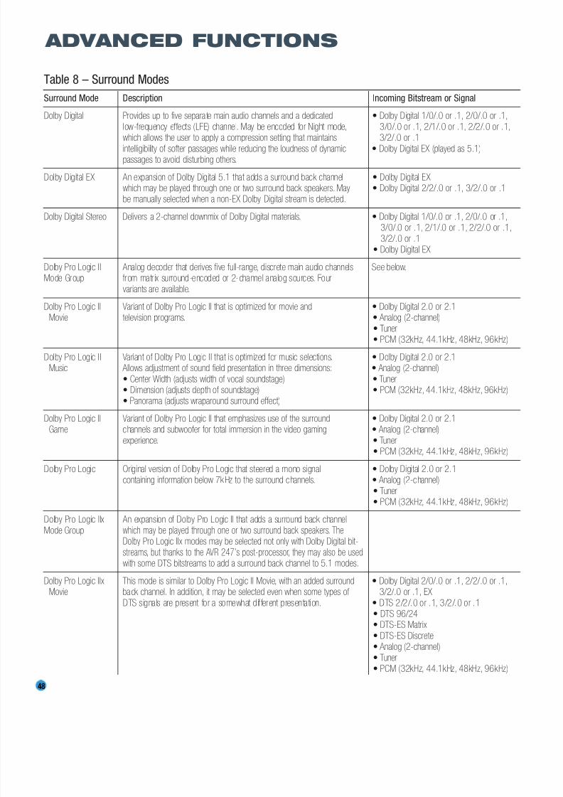
8/2/2019 AVR247om lores
http://slidepdf.com/reader/full/avr247om-lores 48/76
48
Table 8 – Surround Modes
Surround Mode Description Incoming Bitstream or Signal
Dolby Digital Provides up to five separate main audio channels and a dedicated • Dolby Digital 1/0/.0 or .1, 2/0/.0 or .1,
low-frequency effects (LFE) channel. May be encoded for Night mode, 3/0/.0 or .1, 2/1/.0 or .1, 2/2/.0 or .1,
which allows the user to apply a compression setting that maintains 3/2/.0 or .1intelligibility of softer passages while reducing the loudness of dynamic • Dolby Digital EX (played as 5.1)passages to avoid disturbing others.
Dolby Digital EX An expansion of Dolby Digital 5.1 that adds a surround back channel • Dolby Digital EXwhich may be played through one or two surround back speakers. May • Dolby Digital 2/2/.0 or .1, 3/2/.0 or .1be manually selected when a non-EX Dolby Digital stream is detected.
Dolby Digital Stereo Delivers a 2-channel downmix of Dolby Digital materials. • Dolby Digital 1/0/.0 or .1, 2/0/.0 or .1,3/0/.0 or .1, 2/1/.0 or .1, 2/2/.0 or .1,
3/2/.0 or .1• Dolby Digital EX
Dolby Pro Logic II Analog decoder that derives five full-range, discrete main audio channels See below.
Mode Group from matr ix surround-encoded or 2-channel analog sources. Fourvariants are available.
Dolby Pro Logic II Variant of Dolby Pro Logic II that is optimized for movie and • Dolby Digital 2.0 or 2.1Movie television programs. • Analog (2-channel)
• Tuner• PCM (32kHz, 44.1kHz, 48kHz, 96kHz)
Dolby Pro Logic II Variant of Dolby Pro Logic II that is optimized for music selections. • Dolby Digital 2.0 or 2.1Music Allows adjustment of sound field presentation in three dimensions: • Analog (2-channel)
• Center Width (adjusts width of vocal soundstage) • Tuner• Dimension (adjusts depth of soundstage) • PCM (32kHz, 44.1kHz, 48kHz, 96kHz)• Panorama (adjusts wraparound surround effect)
Dolby Pro Logic II Variant of Dolby Pro Logic II that emphasizes use of the surround • Dolby Digital 2.0 or 2.1Game channels and subwoofer for total immersion in the video gaming • Analog (2-channel)
experience. • Tuner• PCM (32kHz, 44.1kHz, 48kHz, 96kHz)
Dolby Pro Logic Original version of Dolby Pro Logic that steered a mono signal • Dolby Digital 2.0 or 2.1containing information below 7kHz to the surround channels. • Analog (2-channel)
• Tuner• PCM (32kHz, 44.1kHz, 48kHz, 96kHz)
Dolby Pro Logic IIx An expansion of Dolby Pro Logic II that adds a surround back channel
Mode Group which may be played through one or two surround back speakers. TheDolby Pro Logic IIx modes may be selected not only with Dolby Digital bit-
streams, but thanks to the AVR 247’s post-processor, they may also be usedwith some DTS bitstreams to add a surround back channel to 5.1 modes.
Dolby Pro Logic IIx This mode is similar to Dolby Pro Logic II Movie, with an added surround • Dolby Digital 2/0/.0 or .1, 2/2/.0 or .1,Movie back channel. In addition, it may be selected even when some types of 3/2/.0 or .1, EX
DTS signals are present for a somewhat dif ferent presentation. • DTS 2/2/.0 or .1, 3/2/.0 or .1• DTS 96/24• DTS-ES Matrix
• DTS-ES Discrete• Analog (2-channel)
• Tuner• PCM (32kHz, 44.1kHz, 48kHz, 96kHz)
ADVANCED FUNCTIONS

8/2/2019 AVR247om lores
http://slidepdf.com/reader/full/avr247om-lores 49/76
49
ADVANCED FUNCTIONS
Surround Mode Description Incoming Bitstream or Signal
Dolby Pro Logic IIx This mode is similar to Dolby Pro Logic II Music, including the availability • Dolby Digital 2/0/.0 or .1, 2/2/.0 or .1,
Music of center width, dimension and panorama adjustments. Dolby Pro Logic IIx 3/2/.0 or .1, EXMusic adds a surround back channel. In addition, it may be selected • DTS 2/2/.0 or .1, 3/2/.0 or .1
even when some types of DTS signals are present. • DTS 96/24
• DTS-ES Matrix• DTS-ES Discrete• Analog (2-channel)
• Tuner• PCM (32kHz, 44.1kHz, 48kHz, 96kHz)
Dolby Pro Logic IIx This mode is similar to Dolby Pro Logic II Game, with the added benefit • Dolby Digital 2/0/.0 or .1
Game of a surround back channel. • Analog (2-channel)• Tuner
• PCM (32kHz, 44.1kHz or 48kHz)
Dolby Virtual Speaker Simulates 5.1 channels when fewer speakers are present, or a more See below.
Mode Group enveloping sound field is desired.
Dolby Virtual Speaker When fewer than five main speakers are present, the Reference • Dolby Digital (uses only two-speaker modeReference mode virtualizes the missing speakers with accurate localization. when signal does not contain center channel
Select from two- or three-speaker mode, depending on how many information)physical speakers are in your system. • Analog (2-channel)
• Tuner• PCM (32kHz, 44.1kHz or 48kHz)
Dolby Virtual Speaker Wide mode may be used with two, three, four or five main speakers to • Dolby Digital (number of channels availableWide widen the front soundstage by vir tualiz ing the locations of the left and varies by number of channels in signal)
right speakers. • Analog (2-channel)• Tuner• PCM (32kHz, 44.1kHz or 48kHz)
DTS Digital Using a different encoding/decoding method than Dolby Digital, it also • DTS 1/0/.0 or .1, 2/0/.0 or .1, 3/0/.0 or .1,provides up to five discrete main channels, plus an LFE channel. 3/1/.0 or .1, 2/2/.0 or .1, 3/2/.0 or .1
• DTS-ES Matrix (played as 5.1)• DTS-ES Discrete (played as 5.1)
DTS-ES Matrix DTS Extended Surround adds a single surround back channel to DTS 5.1 • DTS-ES Matrixdigital surround sound. The Matrix version includes the surround back channel information “matrixed” into the left and right (side) surround
channels, for compatibility with 5.1-channel systems.
DTS-ES Discrete DTS-ES Discrete is another Extended Surround mode that adds a surround • DTS-ES Discrete
back channel, but this information is encoded discretely on the disc, andis not derived from information contained in the surround channels.
DTS Stereo Delivers a 2-channel downmix of DTS Digital materials, or presents • DTS 1/0/.0 or .1, 2/0/.0 or .1, 3/0/.0 or .1,a matrix-encoded surround presentation. 3/1/.0 or .1, 2/2/.0 or .1, 3/2/.0 or .1
• DTS 96/24• DTS-ES Matrix• DTS-ES Discrete
DTS Neo:6 DTS Neo:6 analog processing is available with DTS and DTS 96/24 See below.Mode Group signals and 2-channel analog or PCM signals to create a 3-, 5- or 6-channel
presentation.

8/2/2019 AVR247om lores
http://slidepdf.com/reader/full/avr247om-lores 50/76
50
Surround Mode Description Incoming Bitstream or Signal
DTS Neo:6 Depending on the number of speakers in your system, select 3-, 5- or • DTS 2/2/.0 or .1, 3/2/.0 or .1
Cinema 6-channel modes, enhanced for movie or video presentations. • DTS 96/24
• Analog (2-channel)
• PCM (32kHz, 44.1kHz or 48kHz)
DTS Neo:6 Available only in 5- and 6-channel modes, creates a surround presentation • DTS 2/2/.0 or .1, 3/2/.0 or .1
Music suitable for music recordings. • DTS 96/24
• Analog (2-channel)
• PCM (32kHz, 44.1kHz or 48kHz)
Logic 7 Exclusive to Harman Kardon, Logic 7 enhances 2-channel and matrix-encoded See below.
Mode Group recordings by deriving separate information for the surround back channels.
This provides more accurate placement of sound, improves panning and expands
the sound field, even when used with 5.1-channel systems. Logic 7 uses 96kHz
processing, and is available in 5.1-or 7.1-channel modes. Three variants are available.
Logic 7 Especially suited to 2-channel sources containing Dolby Surround or matrix • Analog (2-channel)
Cinema encoding, Logic 7 Cinema mode increases center channel intelligibility. • Tuner
• PCM (32kHz, 44.1kHz, 48kHz, 96kHz)
Logic 7 The AVR 247 is programmed at the factory to default to this mode for • Analog (2-channel)
Music 2-channel signals. Logic 7 Music mode is well suited to conventional • Tuner
2-channel music recordings. • PCM (32kHz, 44.1kHz, 48kHz, 96kHz)
Logic 7 Logic 7 Enhance circulates low frequencies in the 40Hz – 120Hz range to • Analog (2-channel)
Enhance the main speakers for less local ized bass performance than would be achieved • Tuner
solely with a subwoofer. Enhance mode is best used with music recordings. • PCM (32kHz, 44.1kHz, 48kHz, 96kHz)
Hall 1 Hall 1 is a DSP (digital signal processor) mode that simulates a small • Analog (2-channel)
concert hall. It is available in 5- or 6-channel versions. • Tuner
• PCM (32kHz, 44.1kHz or 48kHz)
Hall 2 Simulates a medium-sized concert hall. It is available in 5- or 6-channel • Analog (2-channel)versions. • Tuner
• PCM (32kHz, 44.1kHz or 48kHz)
Theater Simulates a l ive-performance theater. I t is available in 5- or 6-channel • Analog (2-channel)
versions. • Tuner
• PCM (32kHz, 44.1kHz or 48kHz)
5-Channel Stereo Useful for parties, the left- and right-channel information is played through • Analog (2-channel)
both the front and surround speakers on each side, while the center speaker • Tuner
plays a summed mono mix. • PCM (32kHz, 44.1kHz or 48kHz)
7-Channel Stereo Expands the 5-Channel Stereo presentation to include the surround back • Analog (2-channel)
channels. • Tuner
• PCM (32kHz, 44.1kHz or 48kHz)
DSP Surround Off Turns off all surround processing and plays a pure 2-channel signal. • Analog (2-channel)
The signal is digitized and bass management settings are applied, making it • Tuner
appropriate when a subwoofer is used. • PCM (32kHz, 44.1kHz, 48kHz, 96kHz)
Surround Off Maintains an analog input signal in that form, bypassing all digital processing • Analog (2-channel)
(Analog Bypass) (i.e., surround and bass management). Requires TONE OUT setting. • Tuner
ADVANCED FUNCTIONS
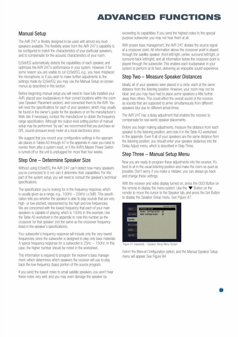
8/2/2019 AVR247om lores
http://slidepdf.com/reader/full/avr247om-lores 51/76
Manual Setup
The AVR 247 is flexibly designed to be used with almost any loud-speakers available. The flexibility arises from the AVR 247’s capability to
be configured to match the characteristics of your particular speakers,and to compensate for the acoustic characteristics of your room.
EzSet/EQ automatically detects the capabilities of each speaker, andoptimizes the AVR 247’s performance in your system. However, if for
some reason you are unable to run EzSet/EQ, e.g., you have misplacedthe microphone, or if you wish to make further adjustments to thesettings made by EzSet/EQ, you may use the Manual Setup on-screen
menus as described in this section.
Before beginning manual setup you will need to have fully installed your
AVR, placed your loudspeakers in their correct locations within the room(see Speaker Placement section), and connected them to the AVR. You
will need the specifications for each of your speakers, which may usuallybe found in the owner’s guide for the speakers or on the manufacturer’s
Web site. If necessary, contact the manufacturer to obtain the frequencyrange specification. Although the output-level setting portion of manualsetup may be performed “by ear,” we recommend that you purchase an
SPL (sound-pressure level) meter at a local electronics store.
We suggest that you record your configuration settings in the appropri-
ate places in Tables A3 through A7 in the appendix in case you need toreenter them after a system reset, or if the AVR’s Master Power Switch
is turned off or the unit is unplugged for more than four weeks.
Step One – Determine Speaker Size
Without using EzSet/EQ, the AVR 247 can’t detect how many speakersyou’ve connected to it; nor can it determine their capabilities. For this
part of the system setup, you will need to consult the speaker’s technicalspecifications.
The specification you’re looking for is the frequency response, whichis usually given as a range, e.g., 100Hz – 20kHz (±3dB). This specifi-cation tells you whether the speaker is able to play sounds that are very
high- or low-pitched, represented by the high and low frequencies.We are concerned with the lowest frequency that each of your main
speakers is capable of playing, which is 100Hz in this example. Usethe Table A5 worksheet in the appendix to note this number as the
crossover for that speaker (not the same as the crossover frequencylisted in the speaker’s specifications).
Your subwoofer’s frequency response will include only the very lowest
frequencies, since the subwoofer is designed to play only bass materials. A typical frequency response for a subwoofer is 25Hz – 150Hz. In this
case, the higher number should be noted in the worksheet.
This information is required to program the receiver’s bass manage-
ment, which determines which speakers the receiver will use to playback the low-frequency (bass) portion of the source program.
If you send the lowest notes to small satellite speakers, you won’t hearthese notes very well, and you may even damage the speaker by
exceeding its capabilities. If you send the highest notes to the special-
purpose subwoofer, you may not hear them at all.
With proper bass management, the AVR 247 divides the source signalat a crossover point. All information above the crossover point is played
through the satellite speaker (front left/right, center, surround left/right, or
surround back left/right), and all information below the crossover point isplayed through the subwoofer. This enables each loudspeaker in yoursystem to perform at its best, delivering an enjoyable sound experience.
Step Two – Measure Speaker Distances
Ideally, all of your speakers were placed in a circle, each at the samedistance from the listening position. However, your room may not beideal, and you may have had to place some speakers a little further
away than others. This could affect the overall sound of the receiver,as sounds that are supposed to arrive simultaneously from different
speakers blur due to different arrival times.
The AVR 247 has a delay adjustment that enables the receiver to
compensate for real-world speaker placements.
Before you begin making adjustments, measure the distance from each
speaker to the listening position, and note it in the Table A3 worksheet in the appendix. Even if all of your speakers are the same distance fromthe listening position, you should enter your speaker distances into the
Delay Adjust menu, which is described in Step Three.
Step Three – Manual Setup Menu
Now you are ready to program these adjustments into the receiver. It’s
best to sit in the usual listening position and make the room as quiet aspossible. Don’t worry if you make a mistake; you can always go back
and change these settings.With the receiver and video display turned on, press the OSD Button onthe remote to display the menu system. Use the¤ Button on the
remote to move the cursor to the Speaker tab, and press the Set Buttonto display the Speaker Setup menu. See Figure 47.
Figure 47 (repeated) – Speaker Setup Menu Screen
Select the Manual Configuration option, and the Manual Speaker Setup
menu will appear. See Figure 84.
51
ADVANCED FUNCTIONS

8/2/2019 AVR247om lores
http://slidepdf.com/reader/full/avr247om-lores 52/76
52
ADVANCED FUNCTIONS
Figure 84 – Manual Speaker Setup Menu
There are four submenus in the Manual Speaker Setup Menu: SpeakerSize, Speaker Crossover, Delay Adjust and Channel Adjust. As each sub-
menu’s name is highlighted, its settings will be displayed. To navigate theManual Speaker Setup menus, press the Set Button when the desired
submenu is highlighted, and the first line of the submenu will be high-lighted. Press the Set Button to change a setting, and use the‹ / ›
Buttons to scroll through the options, pressing the Set Button again toselect an option. Use the⁄ / ¤ Buttons to select another setting in
the submenu. When you are finished making all of your adjustmentsin a particular submenu, press the‹ Button to return to the list of submenus, and use the⁄ / ¤ Buttons to select another submenu.
If you have run EzSet/EQ, the values obtained during that process willappear in these menus. You may use them as a starting point for your
adjustments, which is recommended, or you may reset the values in theDelay Adjust and Channel Adjust submenus.
Each submenu’s settings are dependent upon the previous submenu,and therefore we recommend you visit the menus in the order shown.
Speaker Size Menu
Move the cursor to the Size line and press the Set Button to displaythe Speaker Size submenu. See Figure 84.
The Speaker Size menu lists each of the speaker groups. You will be
programming the correct setting for each group, indicating how manyspeakers are in your system and what their capabilities are, based on
the information you obtained in Step One – Determine Speaker Size.Each of the main speaker groups can be set to one of three settings:
LARGE, SMALL or NONE. These settings don’t refer to the physical sizeof the speaker, but rather to its frequency range. These may or may not turn out to be the same.
If the lower number of the frequency response for your speakers is lessthan 100Hz, choose the LARGE setting. If this number is 100Hz or
greater, choose the SMALL setting. If you don’t have a speaker installedin that position, choose NONE. You may record the speaker size setting
in Table A5 in the appendix.
As you can see, the system requires you to use both speakers in a pair.For example, you can’t connect just a front left speaker without a right
speaker, or just a right surround (rear) speaker without a left one.However, you can connect only the front speakers, or both front and
surround speakers without a center, or the front left/right and centerspeakers without any surrounds.
Usually you would not connect the surround back speakers without also
connecting the front and side surround speakers. However, the AVR 247has the capability to reassign the surround back amplifier channels tothe multiroom system, enabling you to use these channels to power a
pair of speakers in another room independently of the speakers you usein your main listening area. In that case you might connect speakers to
the surround back/multiroom terminals without using the side surroundspeaker terminals at all.
LEFT/RIGHT: This line tells the AVR 247 the capabilities of your front left and right speakers. Press the Set Button and use the‹ / › Buttonsto select either SMALL or LARGE for these speakers.
CENTER: Move the cursor to the line for the center speaker, press theSet Button and use the ‹ / › Buttons to select a setting for this speaker.
NOTE: If the receiver is currently in one of the Logic 7 surroundmodes, which will be the case the first time you turn on the
receiver, you won’t be able to set the center speaker to LARGE,due to the requirements of the Logic 7 processor. You may usethe SMALL setting instead. As you listen to the receiver, if you
find the SMALL setting is not satisfactory, change the surroundmode to one of the Dolby Pro Logic II modes (using the
Surround Select menu, accessible from the Master Menu),and return to this menu to change the center speaker to
the LARGE setting.
SURROUND: Move the cursor to the line for the side surround
speakers, press the Set Button and use the‹ / › Buttons to select the
SMALL, LARGE or NONE setting for these two speakers.
SURR BACK: Press the Set Button and use the ‹ / › Buttons to select
the SMALL, LARGE or NONE setting for the surround back speakers.
The AVR 247 is one of the few receivers in its class to include multiroom
capability. With assignable surround back amplifier channels, setting upa multiroom system is more convenient than ever, no longer requiring
an external amplifier to power the remote speakers. This line indicateswhether the surround back channels are in use with the multiroom systemby indicating MAIN when the multiroom system is not in use and MULTI
when it is. It is not possible to change the status of the surround back channels from this menu; the MAIN/MULTI indication is for information
only. The status may only be changed by activating or deactivating themultiroom system using the MULTI ROOM SETUP menu as described
in the Multiroom Operation section.
SUBWOOFER: Move the cursor to the line for the subwoofer, which isprogrammed a little differently. The subwoofer’s “size” setting depends
upon how you programmed the front left and right speakers.
• If you set the front speakers to SMALL, the subwoofer setting will be
SUB (LFE), and you won’t be able to change it. All low-frequencyinformation will always be sent to the subwoofer. If you don’t have
a subwoofer, you may wish to set your front speakers to LARGEso as not to lose this information, but you may need to lower the
volume to avoid adverse results. We recommend that you eitherupgrade to full-range speakers or add a subwoofer to your systemat the earliest opportunity.
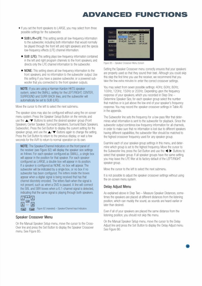
8/2/2019 AVR247om lores
http://slidepdf.com/reader/full/avr247om-lores 53/76
53
ADVANCED FUNCTIONS
• If you set the front speakers to LARGE, you may select from threepossible settings for the subwoofer.
SUB L/R+LFE: This setting sends all low-frequency informationto the subwoofer, including both information that would normally
be played through the front left and right speakers and the special
low-frequency effects (LFE) channel information.
SUB (LFE): This setting plays low-frequency information containedin the left and right program channels to the front speakers, and
directs only the LFE channel information to the subwoofer.
NONE: This setting steers all low-frequency information to thefront speakers, and no information to the subwoofer output. Use
this setting if you have a passive subwoofer, or a powered sub-woofer that you connected to the front speaker outputs.
NOTE: If you are using a Harman Kardon HKTS speakersystem, select the SMALL setting for the LEFT/RIGHT, CENTER,SURROUND and SURR BACK lines, and the subwoofer will
automatically be set to SUB (LFE).
Move the cursor to the left to select the next submenu.
The speaker sizes may also be configured without using the on-screenmenu system. Press the Speaker Setup Button on the remote, anduse the ⁄ / ¤ Buttons to select the desired speaker group (Front Speakers, Center Speaker, Surround Speakers, Surround Back Speakers,Subwoofer). Press the Set Button to display the current setting for thespeaker group, and use the⁄ / ¤ Buttons again to change the setting.Press the Set Button to return to the previous display, or wait a fewseconds for the AVR to return to normal operation on its own.
NOTE: The Speaker/Channel Indicators on the front panel of
the receiver (see Figure 82) will display the speaker size settingsas follows. For each speaker configured as SMALL, a single boxwill appear in the position for that speaker. For each speakerconfigured as LARGE, a double box will appear in its position.If a speaker is configured as NONE, no box will appear. Thesubwoofer will be indicated by a single box, or no box if nosubwoofer has been configured. The letters inside the boxesappear when a digital signal is being received that has that channel discretely encoded. The letters flash when the signal isnot present, such as when a DVD is paused. A line will connect the SBL and SBR boxes when a 6.1-channel signal is detected,indicating that the same signal is playing through both speakers.
Figure 82 (repeated) – Speaker/Channel Input Indicators
Speaker Crossover Menu
On the Manual Speaker Setup menu, move the cursor to the Cross-Over line and press the Set Button to display the Speaker Crossovermenu. See Figure 85.
Figure 85 – Speaker Crossover Menu Screen
Setting the Speaker Crossover menu correctly ensures that your speakersare properly used so that they sound their best. Although you could skip
this step the first time you use the receiver, we recommend that youtake the few extra minutes to enter the correct crossover settings.
You may select from seven possible settings: 40Hz, 60Hz, 80Hz,100Hz, 120Hz, 150Hz or 200Hz. Depending upon the frequency
response of your speakers, which you recorded in Step One –
Determine Speaker Size, for each speaker group select the numberthat matches or is just above the low end of your speaker’s frequencyresponse. You may record the speaker crossover settings in Table A5in the appendix.
The Subwoofer line sets the frequency for a low-pass filter that deter-mines what information is sent to the subwoofer for playback. Since the
subwoofer output combines low-frequency information for all channels,in order to make sure that no information is lost due to different speakers
having different capabilities, the subwoofer filter should be matched tothe highest crossover frequency used for any speaker group.
Examine each of your speaker-group settings in this menu, and deter-mine which group is set to the highest frequency. Move the cursor to
the Subwoofer line, press the Set Button and use the‹ / › Buttons toselect that speaker group. If all speaker groups have the same setting,you may leave the LFE filter at its factory default of the LEFT/RIGHT
speaker group.
Move the cursor to the left to select the next submenu.
It is not possible to adjust the speaker crossover settings without usingthe on-screen menu system.
Delay Adjust Menu
As explained above in Step Two – Measure Speaker Distances, some-
times the speakers are placed at different distances from the listening
position, which can muddy the sound, as sounds are heard earlier orlater than desired.
Even if all of your speakers are placed the same distance from the
listening position, you should not skip this menu.
On the Manual Speaker Setup menu, move the cursor to the Delay
Adjust line and press the Set Button to display the Delay Adjust menu.See Figure 86.
LC
LFE
R
SL SR
SBL SBR
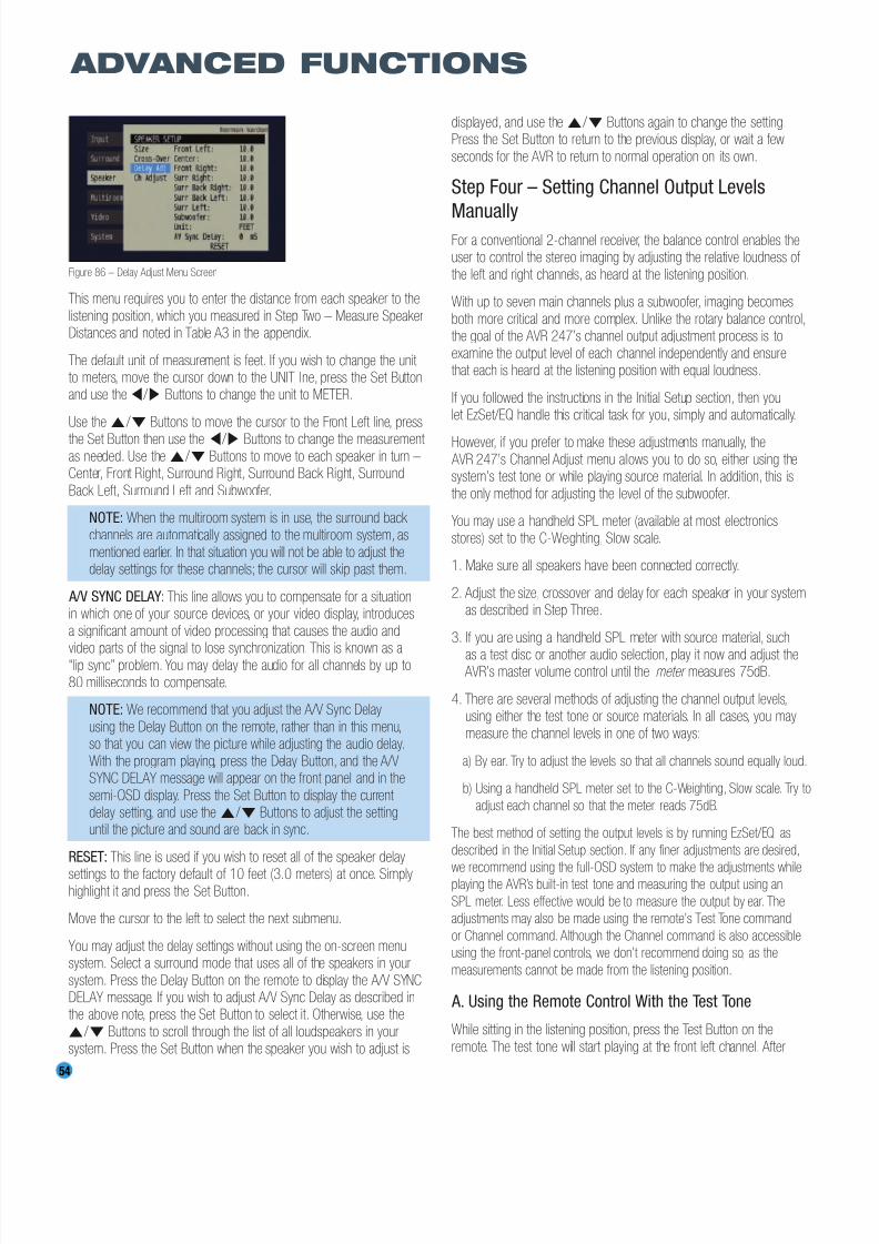
8/2/2019 AVR247om lores
http://slidepdf.com/reader/full/avr247om-lores 54/76
54
ADVANCED FUNCTIONS
Figure 86 – Delay Adjust Menu Screen
This menu requires you to enter the distance from each speaker to the
listening position, which you measured in Step Two – Measure SpeakerDistances and noted in Table A3 in the appendix.
The default unit of measurement is feet. If you wish to change the unit to meters, move the cursor down to the UNIT line, press the Set Buttonand use the ‹ / › Buttons to change the unit to METER.
Use the ⁄ / ¤ Buttons to move the cursor to the Front Left line, press
the Set Button then use the ‹ / › Buttons to change the measurement as needed. Use the ⁄ / ¤ Buttons to move to each speaker in turn –Center, Front Right, Surround Right, Surround Back Right, Surround
Back Left, Surround Left and Subwoofer.
NOTE: When the multiroom system is in use, the surround back channels are automatically assigned to the multiroom system, as
mentioned earlier. In that situation you will not be able to adjust thedelay settings for these channels; the cursor will skip past them.
A/V SYNC DELAY: This line allows you to compensate for a situationin which one of your source devices, or your video display, introduces
a significant amount of video processing that causes the audio and
video parts of the signal to lose synchronization. This is known as a“lip sync” problem. You may delay the audio for all channels by up to80 milliseconds to compensate.
NOTE: We recommend that you adjust the A/V Sync Delay
using the Delay Button on the remote, rather than in this menu,so that you can view the picture while adjusting the audio delay.
With the program playing, press the Delay Button, and the A/VSYNC DELAY message will appear on the front panel and in the
semi-OSD display. Press the Set Button to display the current delay setting, and use the⁄ / ¤ Buttons to adjust the settinguntil the picture and sound are back in sync.
RESET: This line is used if you wish to reset all of the speaker delay
settings to the factory default of 10 feet (3.0 meters) at once. Simplyhighlight it and press the Set Button.
Move the cursor to the left to select the next submenu.
You may adjust the delay settings without using the on-screen menusystem. Select a surround mode that uses all of the speakers in your
system. Press the Delay Button on the remote to display the A/V SYNCDELAY message. If you wish to adjust A/V Sync Delay as described inthe above note, press the Set Button to select it. Otherwise, use the⁄ / ¤ Buttons to scroll through the list of all loudspeakers in yoursystem. Press the Set Button when the speaker you wish to adjust is
displayed, and use the ⁄ / ¤ Buttons again to change the setting.Press the Set Button to return to the previous display, or wait a few
seconds for the AVR to return to normal operation on its own.
Step Four – Setting Channel Output Levels
ManuallyFor a conventional 2-channel receiver, the balance control enables theuser to control the stereo imaging by adjusting the relative loudness of
the left and right channels, as heard at the listening position.
With up to seven main channels plus a subwoofer, imaging becomes
both more critical and more complex. Unlike the rotary balance control,the goal of the AVR 247’s channel output adjustment process is to
examine the output level of each channel independently and ensurethat each is heard at the listening position with equal loudness.
If you followed the instructions in the Initial Setup section, then youlet EzSet/EQ handle this critical task for you, simply and automatically.
However, if you prefer to make these adjustments manually, the
AVR 247’s Channel Adjust menu allows you to do so, either using thesystem’s test tone or while playing source material. In addition, this is
the only method for adjusting the level of the subwoofer.
You may use a handheld SPL meter (available at most electronics
stores) set to the C-Weighting, Slow scale.
1. Make sure all speakers have been connected correctly.
2. Adjust the size, crossover and delay for each speaker in your systemas described in Step Three.
3. If you are using a handheld SPL meter with source material, such
as a test disc or another audio selection, play it now and adjust the AVR’s master volume control until the meter measures 75dB.
4. There are several methods of adjusting the channel output levels,using either the test tone or source materials. In all cases, you may
measure the channel levels in one of two ways:
a) By ear. Try to adjust the levels so that all channels sound equally loud.
b) Using a handheld SPL meter set to the C-Weighting, Slow scale. Try to
adjust each channel so that the meter reads 75dB.
The best method of setting the output levels is by running EzSet/EQ, as
described in the Initial Setup section. If any finer adjustments are desired,
we recommend using the full-OSD system to make the adjustments whileplaying the AVR’s built-in test tone and measuring the output using an
SPL meter. Less effective would be to measure the output by ear. The
adjustments may also be made using the remote’s Test Tone command
or Channel command. Although the Channel command is also accessible
using the front-panel controls, we don’t recommend doing so, as the
measurements cannot be made from the listening position.
A. Using the Remote Control With the Test Tone
While sitting in the listening position, press the Test Button on the
remote. The test tone will start playing at the front left channel. After
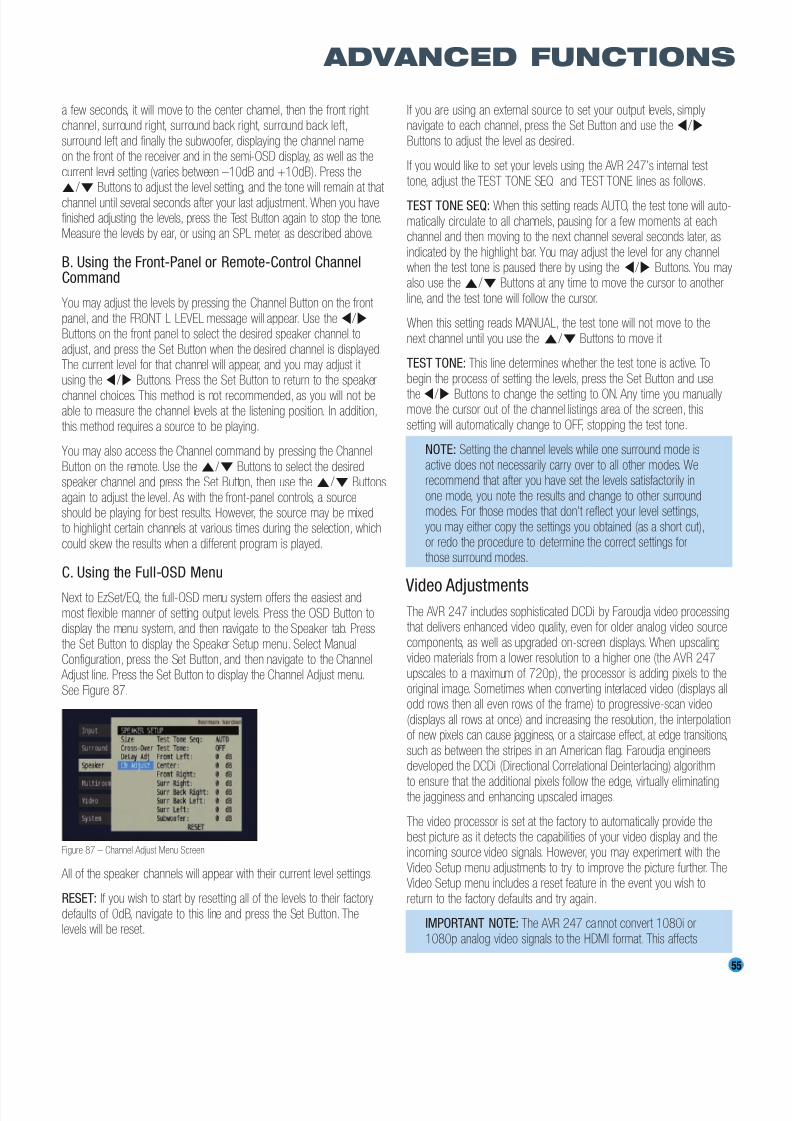
8/2/2019 AVR247om lores
http://slidepdf.com/reader/full/avr247om-lores 55/76
55
ADVANCED FUNCTIONS
a few seconds, it will move to the center channel, then the front right channel, surround right, surround back right, surround back left,
surround left and finally the subwoofer, displaying the channel nameon the front of the receiver and in the semi-OSD display, as well as the
current level setting (varies between –10dB and +10dB). Press the⁄ / ¤ Buttons to adjust the level setting, and the tone will remain at that
channel until several seconds after your last adjustment. When you havefinished adjusting the levels, press the Test Button again to stop the tone.Measure the levels by ear, or using an SPL meter, as described above.
B. Using the Front-Panel or Remote-Control ChannelCommand
You may adjust the levels by pressing the Channel Button on the front
panel, and the FRONT L LEVEL message will appear. Use the ‹ / ›
Buttons on the front panel to select the desired speaker channel to
adjust, and press the Set Button when the desired channel is displayed.The current level for that channel will appear, and you may adjust it using the ‹ / › Buttons. Press the Set Button to return to the speaker
channel choices. This method is not recommended, as you will not beable to measure the channel levels at the listening position. In addition,
this method requires a source to be playing.
You may also access the Channel command by pressing the Channel
Button on the remote. Use the⁄ / ¤ Buttons to select the desiredspeaker channel and press the Set Button, then use the⁄ / ¤ Buttons
again to adjust the level. As with the front-panel controls, a sourceshould be playing for best results. However, the source may be mixedto highlight certain channels at various times during the selection, which
could skew the results when a different program is played.
C. Using the Full-OSD Menu
Next to EzSet/EQ, the full-OSD menu system offers the easiest and
most flexible manner of setting output levels. Press the OSD Button todisplay the menu system, and then navigate to the Speaker tab. Press
the Set Button to display the Speaker Setup menu. Select ManualConfiguration, press the Set Button, and then navigate to the Channel
Adjust line. Press the Set Button to display the Channel Adjust menu.
See Figure 87.
Figure 87 – Channel Adjust Menu Screen
All of the speaker channels will appear with their current level settings.
RESET: If you wish to start by resetting all of the levels to their factory
defaults of 0dB, navigate to this line and press the Set Button. Thelevels will be reset.
If you are using an external source to set your output levels, simplynavigate to each channel, press the Set Button and use the‹ / ›
Buttons to adjust the level as desired.
If you would like to set your levels using the AVR 247’s internal test
tone, adjust the TEST TONE SEQ and TEST TONE lines as follows.
TEST TONE SEQ: When this setting reads AUTO, the test tone will auto-
matically circulate to all channels, pausing for a few moments at eachchannel and then moving to the next channel several seconds later, as
indicated by the highlight bar. You may adjust the level for any channelwhen the test tone is paused there by using the ‹ / › Buttons. You mayalso use the ⁄ / ¤ Buttons at any time to move the cursor to another
line, and the test tone will follow the cursor.
When this setting reads MANUAL, the test tone will not move to the
next channel until you use the ⁄ / ¤ Buttons to move it.
TEST TONE: This line determines whether the test tone is active. To
begin the process of setting the levels, press the Set Button and use
the ‹ / › Buttons to change the setting to ON. Any time you manuallymove the cursor out of the channel listings area of the screen, this
setting will automatically change to OFF, stopping the test tone.
NOTE: Setting the channel levels while one surround mode is
active does not necessarily carry over to all other modes. Werecommend that after you have set the levels satisfactorily in
one mode, you note the results and change to other surroundmodes. For those modes that don’t reflect your level settings,
you may either copy the settings you obtained (as a short cut),or redo the procedure to determine the correct settings forthose surround modes.
Video AdjustmentsThe AVR 247 includes sophisticated DCDi by Faroudja video processingthat delivers enhanced video quality, even for older analog video source
components, as well as upgraded on-screen displays. When upscalingvideo materials from a lower resolution to a higher one (the AVR 247
upscales to a maximum of 720p), the processor is adding pixels to theoriginal image. Sometimes when converting interlaced video (displays allodd rows then all even rows of the frame) to progressive-scan video
(displays all rows at once) and increasing the resolution, the interpolationof new pixels can cause jagginess, or a staircase effect, at edge transitions,
such as between the stripes in an American flag. Faroudja engineersdeveloped the DCDi (Directional Correlational Deinterlacing) algorithm
to ensure that the additional pixels follow the edge, virtually eliminatingthe jagginess and enhancing upscaled images.
The video processor is set at the factory to automatically provide thebest picture as it detects the capabilities of your video display and theincoming source video signals. However, you may experiment with the
Video Setup menu adjustments to try to improve the picture further. TheVideo Setup menu includes a reset feature in the event you wish to
return to the factory defaults and try again.
IMPORTANT NOTE: The AVR 247 cannot convert 1080i or
1080p analog video signals to the HDMI format. This affects

8/2/2019 AVR247om lores
http://slidepdf.com/reader/full/avr247om-lores 56/76
56
ADVANCED FUNCTIONS
users of Microsoft Xbox 360 systems and some older set-topboxes, and the picture cannot be improved by making adjust-
ments in the AVR 247’s Video Setup menu.
If your digital cable television set-top box outputs 1080i or highervideo via component video outputs and is not equipped with an
HDMI output, contact your cable operator for a replacement.For Xbox 360 and satellite television customers, either changethe settings on your source device to ensure that it outputs only720p video through its component video outputs, which the
AVR can convert to the HDMI format, or connect the AVR’sComponent Video Monitor Outputs to the video display.
Although you could connect the source device’s component video outputs directly to your video display, you would then have
to select the correct video input on the display, depending onwhich source input on the AVR was in use.
To access the Video Setup menu, press the OSD Button to display the
menu system, and navigate to the Video tab. Press the Set Button to
access the Video Setup menu, shown in Figure 88.
Figure 88 – Video Setup Menu Screen
Output Format: This setting is used to specify the resolution of the
AVR’s video output as 480i, 480p or 720p.
When the HDMI Output is active, 480i output is not available. If you select the 480i setting and the video display is capable of 720p resolution, the
AVR will automatically select the higher resolution. If the display is not
capable of 720p resolution, the AVR will select the 480p setting.
If your source signal is 1080i or 1080p (must be digital, not analog; see
important note above), it will be passed through to the HDMI Output asis, but you may not select that output format on this line, as upscaling to
these resolutions is not supported. If you are using the Component VideoMonitor Outputs, you will not be able to view 1080p materials, but 1080i
sources will be passed through. In any event, when the source signal is
1080i or 1080p, the semi-OSD messages will not appear, including thevolume bar. Full-OSD displays will appear, but at a lower resolution.
Viewing Preference: This setting allows you to select a factory-predetermined picture setting that is optimized for various types of
program materials. The available options are CINEMA, SPORT, NATUREand VIVID.
Sharpness: You may adjust the Sharpness setting from 0 to 100 in incre-ments of 4 units. We recommend leaving this setting as low as possible, as
contrary to what you might expect, a less sharp image can appear cleareron screen. In addition, increasing the Sharpness requires additional video
processing, which may lead to loss of sync with the audio or visual artifacts.
However, there is no harm in experimenting with this setting.
Brightness: This control adjusts the level at which black is delivered.We recommend leaving it at its factory setting, although there is no
harm in experimenting if you are using a test signal.
Contrast: This control adjusts the difference between black and white
in the picture. We recommend leaving it at its factory setting, althoughthere is no harm in experimenting if you are using a test signal.
Color: This control adjusts the hue of the colors in the picture, andmay be set between 0 and 99. Select a setting in which people and
objects on screen look natural. There is no “recommended” setting,and no harm in experimenting.
Reset: If you wish to return the video settings to their factory defaults,
select this line and press the Set Button.
Multiroom Operation
The AVR 247 offers the benefits of multiroom operation, a rarity in a
receiver this affordable.With the multiroom system in use, you mayenjoy an exciting 5.1-channel home theater presentation in the main
listening area, while others listen to the same materials or an entirelydifferent presentation in another room.
Although installation of a multiroom system is not complicated, it is often
accomplished by running wires inside walls. We urge you to check yourlocal building codes and comply with the requirements for in-wall wiring
systems to prevent the possibility of a dangerous situation. If you haveany questions about installing a multiroom system, we strongly recom-
mend that you contact a professional custom installer in your area.
Installing a Multiroom System
A typical multiroom system consists of only one remote room in theremote zone. That is, you connect only one pair of loudspeakers to the
AVR 247, placing those speakers in the remote room the same wayyou would place the front left and right speakers in the main listeningroom. It is not recommended that you separate the left and right multiroom speakers, unless you will only use the system with the tuneras the source, and you have pressed the Tuning Mode Button to select monaural operation for FM radio stations.
If you wish to use the AVR 247 with more than one remote room, youwill need to purchase a multichannel external amplifier that enables you
to connect several pairs of loudspeakers. However, the AVR 247 onlyoutputs one remote zone, meaning that only one signal is sent throughthe multiroom system. All remote rooms will hear the same source,even when a multichannel amplifier is used.
There are two ways of connecting the remote speakers to the AVR 247:
a) Connect the speakers to the left and right Surround Back/MultiroomSpeaker Outputs on the rear panel of the AVR 247. This is thesimplest type of multiroom system. However, it is not recommendedfor long speaker-wire runs (e.g., more than 25 feet), as the audiosignal tends to degrade over long distances. If your application wouldrequire a long speaker-wire run, consider option b) below.
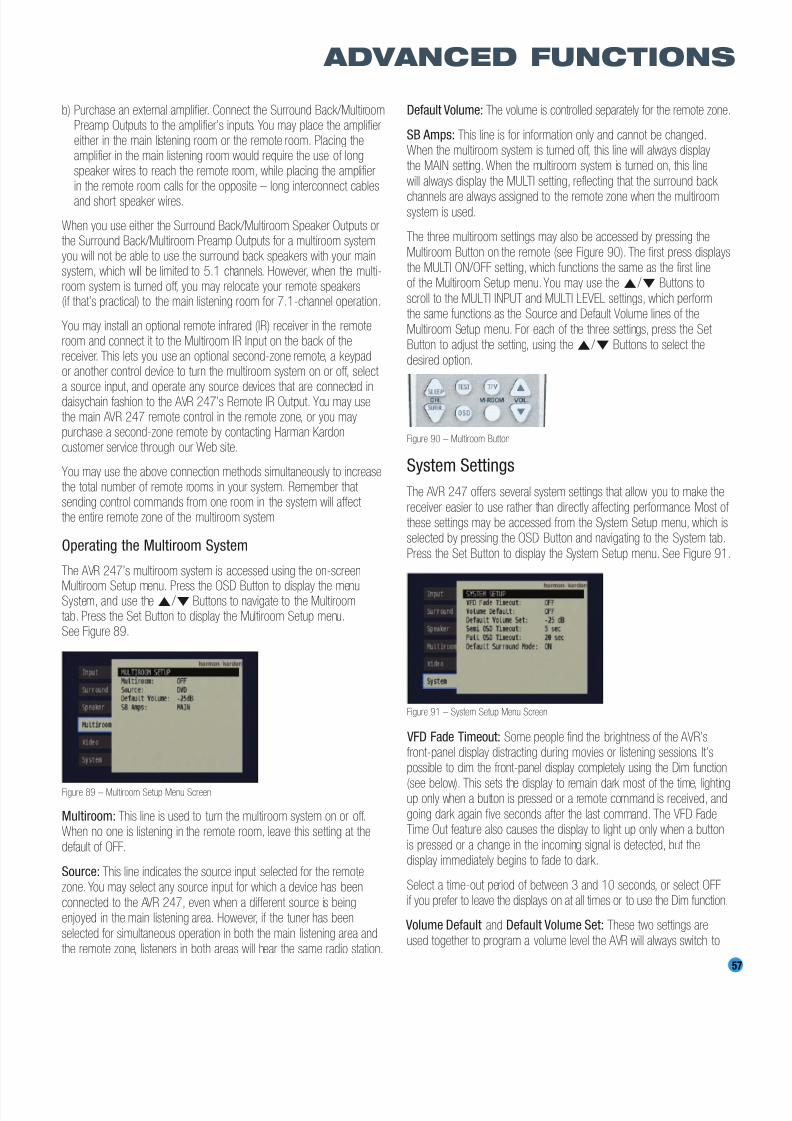
8/2/2019 AVR247om lores
http://slidepdf.com/reader/full/avr247om-lores 57/76
b) Purchase an external amplifier. Connect the Surround Back/MultiroomPreamp Outputs to the amplifier’s inputs. You may place the amplifiereither in the main listening room or the remote room. Placing theamplifier in the main listening room would require the use of longspeaker wires to reach the remote room, while placing the amplifierin the remote room calls for the opposite – long interconnect cables
and short speaker wires.
When you use either the Surround Back/Multiroom Speaker Outputs orthe Surround Back/Multiroom Preamp Outputs for a multiroom system,you will not be able to use the surround back speakers with your mainsystem, which will be limited to 5.1 channels. However, when the multi-room system is turned off, you may relocate your remote speakers(if that’s practical) to the main listening room for 7.1-channel operation.
You may install an optional remote infrared (IR) receiver in the remoteroom and connect it to the Multiroom IR Input on the back of thereceiver. This lets you use an optional second-zone remote, a keypador another control device to turn the multiroom system on or off, select
a source input, and operate any source devices that are connected indaisychain fashion to the AVR 247’s Remote IR Output. You may usethe main AVR 247 remote control in the remote zone, or you maypurchase a second-zone remote by contacting Harman Kardoncustomer service through our Web site.
You may use the above connection methods simultaneously to increasethe total number of remote rooms in your system. Remember that sending control commands from one room in the system will affect the entire remote zone of the multiroom system.
Operating the Multiroom System
The AVR 247’s multiroom system is accessed using the on-screen
Multiroom Setup menu. Press the OSD Button to display the menuSystem, and use the ⁄ / ¤ Buttons to navigate to the Multiroomtab. Press the Set Button to display the Multiroom Setup menu.See Figure 89.
Figure 89 – Multiroom Setup Menu Screen
Multiroom: This line is used to turn the multiroom system on or off.When no one is listening in the remote room, leave this setting at thedefault of OFF.
Source: This line indicates the source input selected for the remotezone. You may select any source input for which a device has been
connected to the AVR 247, even when a different source is beingenjoyed in the main listening area. However, if the tuner has been
selected for simultaneous operation in both the main listening area andthe remote zone, listeners in both areas will hear the same radio station.
Default Volume: The volume is controlled separately for the remote zone.
SB Amps: This line is for information only and cannot be changed.When the multiroom system is turned off, this line will always displaythe MAIN setting. When the multiroom system is turned on, this line
will always display the MULTI setting, reflecting that the surround back
channels are always assigned to the remote zone when the multiroomsystem is used.
The three multiroom settings may also be accessed by pressing the
Multiroom Button on the remote (see Figure 90). The first press displaysthe MULTI ON/OFF setting, which functions the same as the first lineof the Multiroom Setup menu. You may use the⁄ / ¤ Buttons to
scroll to the MULTI INPUT and MULTI LEVEL settings, which performthe same functions as the Source and Default Volume lines of the
Multiroom Setup menu. For each of the three settings, press the Set Button to adjust the setting, using the⁄ / ¤ Buttons to select the
desired option.
Figure 90 – Multiroom Button
System Settings
The AVR 247 offers several system settings that allow you to make the
receiver easier to use rather than directly affecting performance. Most of these settings may be accessed from the System Setup menu, which isselected by pressing the OSD Button and navigating to the System tab.
Press the Set Button to display the System Setup menu. See Figure 91.
Figure 91 – System Setup Menu Screen
VFD Fade Timeout: Some people find the brightness of the AVR’sfront-panel display distracting during movies or listening sessions. It’spossible to dim the front-panel display completely using the Dim function
(see below). This sets the display to remain dark most of the time, lightingup only when a button is pressed or a remote command is received, and
going dark again five seconds after the last command. The VFD FadeTime Out feature also causes the display to light up only when a button
is pressed or a change in the incoming signal is detected, but thedisplay immediately begins to fade to dark.
Select a time-out period of between 3 and 10 seconds, or select OFFif you prefer to leave the displays on at all times or to use the Dim function.
Volume Default and Default Volume Set: These two settings are
used together to program a volume level the AVR will always switch to
57
ADVANCED FUNCTIONS
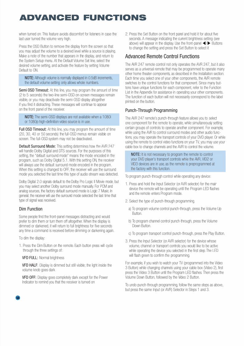
8/2/2019 AVR247om lores
http://slidepdf.com/reader/full/avr247om-lores 58/76
58
ADVANCED FUNCTIONS
when turned on. This feature avoids discomfort for listeners in case thelast user turned the volume very high.
Press the OSD Button to remove the display from the screen so that you may adjust the volume to a desired level while a source is playing.
Make a note of the number that appears in the display, and return to
the System Setup menu. At the Default Volume Set line, select thedesired volume setting, and activate the feature by setting VolumeDefault to ON.
NOTE: Although volume is normally displayed in 0.5dB increments,the default volume setting only allows whole numbers.
Semi OSD Timeout: At this line, you may program the amount of time
(2 to 5 seconds) the two-line semi-OSD on-screen messages remainvisible, or you may deactivate the semi-OSD display altogether
if you find it distracting. These messages will continue to appearon the front panel of the receiver.
NOTE: The semi-OSD displays are not available when a 1080i
or 1080p high-definition video source is in use.
Full OSD Timeout: At this line, you may program the amount of time(20, 30, 40 or 50 seconds) the full-OSD menus remain visible onscreen. The full-OSD system may not be deactivated.
Default Surround Mode: This setting determines how the AVR 247will handle Dolby Digital and DTS sources. For the purposes of thissetting, the “default surround mode” means the mode encoded in theprogram, such as Dolby Digital 5.1. With this setting ON, the receiverwill always use the default surround mode encoded in the program.When this setting is changed to OFF, the receiver will use the surroundmode you selected the last time this type of audio stream was detected.
Dolby Digital 2.0 signals default to the Dolby Pro Logic II Movie mode, but you may select another Dolby surround mode manually. For PCM andanalog sources, the factory default surround mode is Logic 7 Music. Ingeneral, the receiver will use the surround mode selected the last time that type of signal was received.
Dim Function
Some people find the front-panel messages distracting and wouldprefer to dim them or turn them off altogether. When the display isdimmed or darkened, it will return to full brightness for five secondsany time a command is received before dimming or darkening again.
To dim the display:
1. Press the Dim Button on the remote. Each button press will cyclethrough the three settings of:
VFD FULL: Normal brightness
VFD HALF: Display is dimmed but still visible; the light inside thevolume knob goes dark
VFD OFF: Display goes completely dark except for the PowerIndicator to remind you that the receiver is turned on
2. Press the Set Button on the front panel and hold it for about fiveseconds. A message indicating the current brightness setting (seeabove) will appear in the display. Use the front-panel‹ / › Buttonsto change the setting and press the Set Button to select it.
Advanced Remote Control Functions
The AVR 247 remote control not only operates the AVR 247, but it alsoserves as a universal remote that may be programmed to operate manyother home theater components, as described in the Installation section.Each time you select one of your other components, the AVR remoteswitches to the control functions for that component. Since many but-tons have unique functions for each component, refer to the FunctionList in the Appendix for assistance in operating your other components.The function of each button will not necessarily correspond to the labelprinted on the button.
Punch-Through Programming
The AVR 247 remote’s punch-through feature allows you to select one component for the remote to operate, while simultaneously setting
certain groups of controls to operate another component. For example,while using the AVR to control surround modes and other audio func-
tions, you may operate the transport controls of your DVD player. Or whileusing the remote to control video functions on your TV, you may use your
cable box to change channels and the AVR to control the volume.
NOTE: It is not necessary to program the remote to controlyour DVD player’s transport controls while the AVR, VID2 or
VID3 devices are in use, as the remote is preprogrammed at the factory with this function.
To program punch-through control while operating any device:
1. Press and hold the Input Selector (or AVR selector) for the main
device the remote will be operating until the Program LED flashesand the remote enters Program mode.
2. Select the type of punch-through programming.
a) To program volume control punch-through, press the Volume Up
Button.
b) To program channel control punch-through, press the VolumeDown Button.
c) To program transport control punch-through, press the Play Button.
3. Press the Input Selector (or AVR selector) for the device whosevolume, channel or transport controls you would like to be activewhile operating the device you selected in the first step. The LED
will flash green to confirm the programming.
For example, if you wish to watch your TV (programmed into the Video
3 Button) while changing channels using your cable box (Video 2), first press the Video 3 Button until the Program LED flashes. Then press theVolume Down Button, followed by the Video 2 Button.
To undo punch-through programming, follow the same steps as above,but press the same Input (or AVR) Selector in Steps 1 and 3.
8/2/2019 AVR247om lores
http://slidepdf.com/reader/full/avr247om-lores 59/76
59
ADVANCED FUNCTIONS
You may reassign the transport control punch-through programming forthe AVR, VID2 and VID3 devices to other devices, such as CD. If you
wish to remove transport control punch-through altogether for the AVR,VID2 or VID3 device, follow the same procedure as for programming
punch-through, but in Step 3 press either of the other two of these threespecial selector buttons. For example, to remove punch-through trans-
port control from the VID3 device so that pressing any of the transport controls will have no effect in that device mode, press and hold VID3until the Program Indicator Program LED flashes in amber, then press
the Play button, followed by either the AVR or VID2 Button.
Macros
Macros are used to program sequences of up to 19 commands that
are executed with a single button press. Macros are well suited forpower on and off commands, or to send out a favorite multidigit channel
number with one button press, or to have the ability to send out a codesequence to control another device while the remote is operating onedevice, but with more flexibility than the built-in punch-through controls.
Some commands may not be programmed into macros: Mute, Dim,Channel Up/Down, or any of the surround mode commands.
NOTE: Use caution when programming complicated macros. It isn’t possible to program a pause or delay before sending com-
mands after Power On, and the component may not be readyto respond to commands instantaneously after powering on.
To program, or “record” a macro, follow these steps:
1. Simultaneously press and hold one of the four Macro Buttons (or the
Power On Button) and the Mute Button to enter Program mode.
2. Press the Input (or AVR) Selector for each device before you entercommands to be transmitted to that device. This step counts as one
of the 19 commands allowed for each macro.
NOTE: Even if you previously switched one of the dual-source
Input Selectors (DVD/CD, TAPE/THE BRIDGE, HDMI 1/HDMI 2)to the primary or secondary source prior to programming the
macro, the remote always requires you to press any of theseselectors once to program the macro to select the primarysource and twice for the secondary source.
3. For the Power On command, DO NOT press the Power On Button.Press the Mute Button instead.
4. Press the Power Off Button to program the Power Off command.
5. Press the Sleep Button to end the programming process.
It isn’t possible to “edit” a command within a macro. However, you mayerase the macro as follows:
1. Simultaneously press and hold the Mute Button and the MacroButton containing the macro until the Program LED flashes.
2. Press the Surround Button to erase the macro.
Resetting the Remote
To reset the remote to its factory defaults, simultaneously press and hold
any Input Selector and the “0” Numeric key. When the Program LEDflashes in amber, enter the code “333”. When the green LED goes out,
the remote will have been fully reset.
Processor Reset
There may be instances when you wish to fully reset the AVR 247 to its
factory defaults, or the unit may behave erratically after a power surge.
To correct erratic behavior, first try turning the Master Power Switch off and unplugging the AC power cord for at least three minutes. Plug
the cord back in and turn the receiver back on. If this doesn’t help,try a system reset.
NOTES:• A system reset erases all user configurations, including
speaker and level settings and tuner presets. After a reset,
you will need to reenter all of these settings.
• The RS-232 Reset Button on the rear panel of the AVR 247does not perform a system reset. DO NOT press the RS-232Reset Button.
To reset the AVR 247, place the receiver in Standby mode (press thefront-panel Standby/On Switch so that the Power Indicator turns amber).
Then press and hold the front-panel Tone Mode Button for at least fiveseconds until the RESET message appears in the display.
If the receiver still does not function correctly after a processor reset,contact an authorized Harman Kardon service center for assistance.
Authorized service centers may be located by visiting our Web site
at www.harmankardon.com.
Memory
If the AVR 247 is unplugged or experiences a power outage, it will
retain user settings for up to four weeks.

8/2/2019 AVR247om lores
http://slidepdf.com/reader/full/avr247om-lores 60/76
60
SYMPTOM CAUSE SOLUTION
Unit does not function when Main • No AC Power • Make certain AC power cord is plugged intoPower Switch is pushed a live outlet
• Check to see whether outlet is switch-controlled
Display lights, but no sound • Intermittent input connections • Make certain that all input and speaker connectionsor picture are secure• Mute is on • Press Mute Button• Volume control is down • Turn up volume control
No sound from any speaker; • Amplifier is in protection mode • Check speaker wire connections for shorts at receiver andlight around power switch is red due to possible short speaker ends
• Amplifier is in protection mode • Contact your local Harman Kardon service centerdue to internal problems
No sound from surround or • Incorrect surround mode • Select a mode other than Stereocenter speakers • Input is monaural • There is no surround information from mono sources
• Incorrect configuration • Check speaker mode configuration• Stereo or Mono program material • The surround decoder may not create center- or rear-channel
information from nonencoded programs
Unit does not respond to • Weak batteries in remote • Change remote batteriesremote commands • Wrong device selected • Press the AVR selector
• Remote sensor is obscured • Make certain front-panel sensor is in l ine of sight of remoteor connect an optional remote sensor
Intermittent buzzing in tuner • Local interference • Move unit or antenna away from computers, fluorescent lights, motors or other electrical appliances
Letters flash in the channel indicator • Digital audio feed paused • Resume play for DVDdisplay and digital audio stops • Check that the correct digital input is selected
Surround Back Speaker settings • Multiroom system has been turned on, • Use the OSD menu system to access the Multiroom Setup
cannot be accessed, and test tone and the surround back channels menu and turn off the multiroom system.
does not play through Surround were reassigned to multiroom operationBack Speakers
The XM Preview Channel (001) • XM antenna is not plugged in • Make sure you are using a home audio XM antenna module
is silent designed for use with XM Ready home audio equipment,and that the module is plugged into the XM Radio Jack on the rear panel of the receiver.
• XM antenna is not located in such • The XM Antenna module needs to be placed with ana way as to enable reception unobstructed view of the southern sky, or within range of an
XM terrestrial repeater. If necessary, purchase an extensioncable from your XM Radio dealer.
Unable to activate Program mode • Input Selector not held for at least • The selector will light as you initially press it, and go dark as youon remote 3 seconds hold it down. Wait at least 3 seconds for the selector to light
up again, and the Program LED will flash.
Unable to assign a device to • Invalid device assignment attempted • Only the DVD, VCR (includes DVR), cable or satellite (CBL/SATHDMI 1 or 2 selectors selector) devices may be assigned to the HDMI 1 or 2 selectors.
Remote behaves erratically • Buttons are pressed too hard • Always press remote control buttons as gently as possible.
Additional information on troubleshooting possible problems with your AVR 247, or installation-related issues, may be found in the list of “Frequently Asked Questions”, which is located in the Product Support section of our Web site at www.harmankardon.com.
TROUBLESHOOTING GUIDE
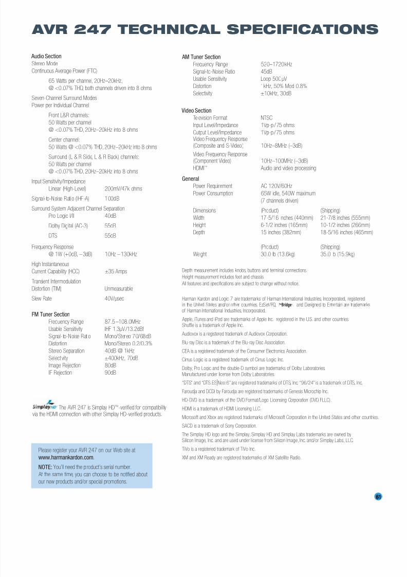
8/2/2019 AVR247om lores
http://slidepdf.com/reader/full/avr247om-lores 61/76
61
Audio Section
Stereo Mode
Continuous Average Power (FTC)
65 Watts per channel, 20Hz–20kHz,
@ <0.07% THD, both channels driven into 8 ohms
Seven-Channel Surround Modes
Power per Individual Channel
Front L&R channels:
50 Watts per channel
@ <0.07% THD, 20Hz–20kHz into 8 ohms
Center channel:
50 Watts @ <0.07% THD, 20Hz–20kHz into 8 ohms
Surround (L & R Side, L & R Back) channels:
50 Watts per channel
@ <0.07% THD, 20Hz–20kHz into 8 ohms
Input Sensitivity/Impedance
Linear (High-Level) 200mV/47k ohms
Signal-to-Noise Ratio (IHF-A) 100dB
Surround System Adjacent Channel Separation
Pro Logic I/II 40dB
Dolby Digital (AC-3) 55dB
DTS 55dB
Frequency Response
@ 1W (+0dB, –3dB) 10Hz –130kHz
High Instantaneous
Current Capability (HCC) ±35 Amps
Transient Intermodulation
Distortion (TIM) Unmeasurable
Slew Rate 40V/µsec
FM Tuner Section
Frequency Range 87.5 –108.0MHz
Usable Sensitivity IHF 1.3µV /13.2dBf
Signal-to-Noise Ratio Mono/Stereo 70/68dB
Distortion Mono/Stereo 0.2/0.3%
Stereo Separation 40dB @ 1kHz
Selectivity ±400kHz, 70dB
Image Rejection 80dB
IF Rejection 90dB
The AVR 247 is Simplay HD™-verified for compatibilityvia the HDMI connection with other Simplay HD-verified products.
AM Tuner Section
Frequency Range 520–1720kHz
Signal-to-Noise Ratio 45dB
Usable Sensitivity Loop 500µV
Distortion 1kHz, 50% Mod 0.8%
Selectivity ±10kHz, 30dB
Video Section
Television Format NTSC
Input Level/Impedance 1Vp-p / 75 ohms
Output Level/Impedance 1Vp-p/75 ohmsVideo Frequency Response(Composite and S-Video) 10Hz–8MHz (–3dB)
Video Frequency Response(Component Video) 10Hz–100MHz (–3dB)
HDMI™ Audio and video processing
General
Power Requirement AC 120V/60Hz
Power Consumption 65W idle, 540W maximum
(7 channels driven)Dimensions (Product) (Shipping)
Width 17-5/16 inches (440mm) 21-7/8 inches (555mm)
Height 6-1/2 inches (165mm) 10-1/2 inches (266mm)
Depth 15 inches (382mm) 18-5/16 inches (465mm)
(Product) (Shipping)
Weight 30.0 lb (13.6kg) 35.0 lb (15.9kg)
Depth measurement includes knobs, buttons and terminal connections.
Height measurement includes feet and chassis.
All features and specifications are subject to change without notice.
Harman Kardon and Logic 7 are trademarks of Harman International Industries, Incorporated, registered
in the United States and/or other countries. EzSet/EQ, and Designed to Entertain are trademarksof Harman International Industries, Incorporated.
Apple, iTunes and iPod are trademarks of Apple Inc., registered in the U.S. and other countries.Shuffle is a trademark of Apple Inc.
Audiovox is a registered trademark of Audiovox Corporation.
Blu-ray Disc is a trademark of the Blu-ray Disc Association.
CEA is a registered trademark of the Consumer Electronics Association.
Cirrus Logic is a registered trademark of Cirrus Logic, Inc.
Dolby, Pro Logic and the double-D symbol are trademarks of Dolby Laboratories.Manufactured under license from Dolby Laboratories.
“DTS” and “DTS ESINeo:6” are registered trademarks of DTS, Inc. “96/24” is a trademark of DTS, Inc.
Faroudja and DCDi by Faroudja are registered trademarks of Genesis Microchip Inc.
HD-DVD is a trademark of the DVD Format/Logo Licensing Corporation (DVD FLLC).
HDMI is a trademark of HDMI Licensing LLC.
Microsoft and Xbox are registered trademarks of Microsoft Corporation in the United States and other countries.
SACD is a trademark of Sony Corporation.
The Simplay HD logo and the Simplay, Simplay HD and Simplay Labs trademarks are owned bySilicon Image, Inc. and are used under license from Silicon Image, Inc. and/or Simplay Labs, LLC.
TiVo is a registered trademark of TiVo Inc.
XM and XM Ready are registered trademarks of XM Satellite Radio.
TheBridgeTM
AVR 247 TECHNICAL SPECIFICATIONS
Please register your AVR 247 on our Web site at
www.harmankardon.com.
NOTE: You’ll need the product’s serial number.
At the same time, you can choose to be notified about
our new products and/or special promotions.
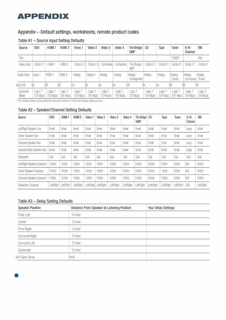
8/2/2019 AVR247om lores
http://slidepdf.com/reader/full/avr247om-lores 62/76
62
Appendix – Default settings, worksheets, remote product codes
Table A1 – Source Input Setting Defaults
Source DVD HDMI 1 HDMI 2 Video 1 Video 2 Video 3 Video 4 The Bridge/ CD Tape Tuner 6-/8- XM
DMP Channel
Title TUNER XM
Video Input Comp V 1 HDMI 1 HDMI 2 Comp V 2 Comp V 3 Composite Composite The Bridge/ Comp V1 Comp V1 Comp V1 Comp V1 Comp V1DMP
Audio Input Coax 1 HDMI 1 HDMI 2 Analog Optical 1 Analog Analog Analog Analog Analog Analog Analog Analog
(The Bridge/DMP) (Tuner) (6-/8-Channel) (Tuner)
Auto Poll On Off Off On On On On Off On On Off Off Off
Surround Logic 7 Logic 7 Logic 7 Logic 7 Logic 7 Logic 7 Logic 7 Logic 7 Logic 7 Logic 7 Logic 7 Logic 7 Logic 7
Mode† 7CH Music 7CH Music 7CH Music 7CH Music 7CH Music 7CH Music 7CH Music 7CH Music 7CH Music 7CH Music 7CH Music 7CH Music 7CH Music
The default shown is the preferred surround mode for PCM and Analog audio sources.
Table A2 – Speaker/Channel Setting DefaultsSource DVD HDMI 1 HDMI 2 Video 1 Video 2 Video 3 Video 4 The Bridge/ CD Tape Tuner 6-/8- XM
DMP Channel
Left/Right Speaker Size Small Small Small Small Small Small Small Small Small Small Small Large Small
Center Speaker Size Small Small Small Small Small Small Small Small Small Small Small Large Small
Surround Speaker Size Small Small Small Small Small Small Small Small Small Small Small Large Small
Surround Back Speaker Size Small Small Small Small Small Small Small Small Small Small Small Large Small
Subwoofer Sub Sub Sub Sub Sub Sub Sub Sub Sub Sub Sub Sub Sub
Left/Right Speaker Crossover 100Hz 100Hz 100Hz 100Hz 100Hz 100Hz 100Hz 100Hz 100Hz 100Hz 100Hz N/A 100Hz
Center Speaker Crossover 100Hz 100Hz 100Hz 100Hz 100Hz 100Hz 100Hz 100Hz 100Hz 100Hz 100Hz N/A 100Hz
Surround Speaker Crossover 100Hz 100Hz 100Hz 100Hz 100Hz 100Hz 100Hz 100Hz 100Hz 100Hz 100Hz N/A 100Hz
Subwoofer Crossover Left/Right Left/Right Left/Right Left/Right Left/Right Left/Right Left/Right Left/Right Left/Right Left/Right Left/Right N/A Left/Right
Table A3 – Delay Setting Defaults
Speaker Position Distance From Speaker to Listening Position Your Delay Settings
Front Left 10 feet
Center 10 feet
Front Right 10 feet
Surround Right 10 feet
Surround Left 10 feet
Subwoofer 10 feet
A/V Sync Delay 0mS
APPENDIX
†
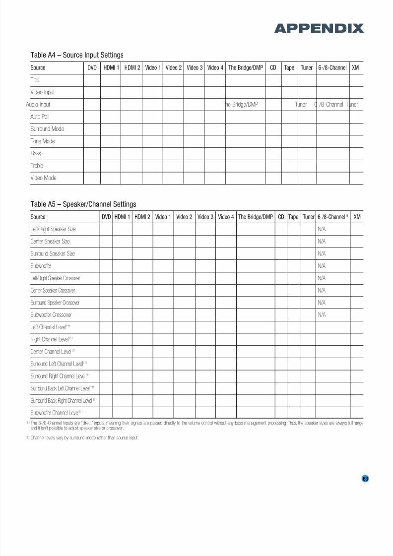
8/2/2019 AVR247om lores
http://slidepdf.com/reader/full/avr247om-lores 63/76
63
Table A4 – Source Input Settings
Source DVD HDMI 1 HDMI 2 Video 1 Video 2 Video 3 Video 4 The Bridge/DMP CD Tape Tuner 6-/8-Channel XM
Title
Video Input
Audio Input The Bridge/DMP Tuner 6-/8-Channel Tuner
Auto Poll
Surround Mode
Tone Mode
Bass
Treble
Video Mode
Table A5 – Speaker/Channel Settings
Source DVD HDMI 1 HDMI 2 Video 1 Video 2 Video 3 Video 4 The Bridge/DMP CD Tape Tuner 6-/8-Channel†† XM
Left/Right Speaker Size N/A
Center Speaker Size N/A
Surround Speaker Size N/A
Subwoofer N/A
Left/Right Speaker Crossover N/A
Center Speaker Crossover N/A
Surround Speaker Crossover N/A
Subwoofer Crossover N/A
Left Channel Level†††
Right Channel Level†††
Center Channel Level†††
Surround Left Channel Level†††
Surround Right Channel Level†††
Surround Back Left Channel Level†††
Surround Back Right Channel Level†††
Subwoofer Channel Level†††
The 6-/8-Channel Inputs are “direct” inputs, meaning their signals are passed directly to the volume control without any bass management processing. Thus, the speaker sizes are always full range,and it isn’t possible to adjust speaker size or crossover.
Channel levels vary by surround mode rather than source input.
APPENDIX
††
†††
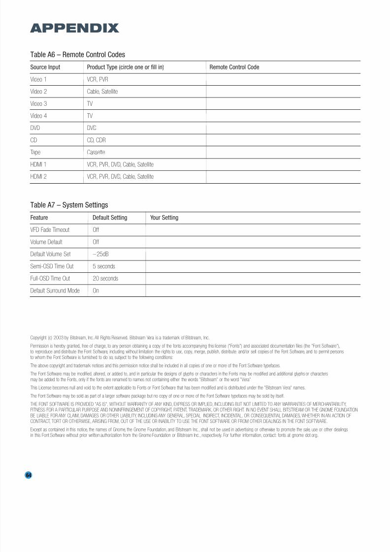
8/2/2019 AVR247om lores
http://slidepdf.com/reader/full/avr247om-lores 64/76
64
Table A6 – Remote Control Codes
Source Input Product Type (circle one or fill in) Remote Control Code
Video 1 VCR, PVR
Video 2 Cable, Satellite
Video 3 TV
Video 4 TV
DVD DVD
CD CD, CDR
Tape Cassette
HDMI 1 VCR, PVR, DVD, Cable, Satellite
HDMI 2 VCR, PVR, DVD, Cable, Satellite
Table A7 – System Settings
Feature Default Setting Your Setting
VFD Fade Timeout Off
Volume Default Off
Default Volume Set –25dB
Semi-OSD Time Out 5 seconds
Full-OSD Time Out 20 seconds
Default Surround Mode On
Copyright (c) 2003 by Bitstream, Inc. All Rights Reserved. Bitstream Vera is a trademark of Bitstream, Inc.
Permission is hereby granted, free of charge, to any person obtaining a copy of the fonts accompanying this license ("Fonts") and associated documentation files (the "Font Software"),to reproduce and distribute the Font Software, including without limitation the rights to use, copy, merge, publish, distribute, and/or sell copies of the Font Software, and to permit personsto whom the Font Software is furnished to do so, subject to the following conditions:
The above copyright and trademark notices and this permission notice shall be included in all copies of one or more of the Font Software typefaces.
The Font Software may be modified, altered, or added to, and in particular the designs of glyphs or characters in the Fonts may be modified and additional glyphs or charactersmay be added to the Fonts, only if the fonts are renamed to names not containing either the words "Bitstream" or the word "Vera".
This License becomes null and void to the extent applicable to Fonts or Font Software that has been modified and is distributed under the "Bitstream Vera" names.
The Font Software may be sold as part of a larger software package but no copy of one or more of the Font Software typefaces may be sold by itself.
THE FONT SOFTWARE IS PROVIDED "AS IS", WITHOUT WARRANTY OF ANY KIND, EXPRESS OR IMPLIED, INCLUDING BUT NOT LIMITED TO ANY WARRANTIES OF MERCHANTABILITY,FITNESS FOR A PARTICULAR PURPOSE AND NONINFRINGEMENT OF COPYRIGHT, PATENT, TRADEMARK, OR OTHER RIGHT. IN NO EVENT SHALL BITSTREAM OR THE GNOME FOUNDATIONBE LIABLE FOR ANY CLAIM, DAMAGES OR OTHER LIABILITY, INCLUDING ANY GENERAL, SPECIAL, INDIRECT, INCIDENTAL, OR CONSEQUENTIAL DAMAGES, WHETHER IN AN ACTION OFCONTRACT, TORT OR OTHERWISE, ARISING FROM, OUT OF THE USE OR INABILITY TO USE THE FONT SOFTWARE OR FROM OTHER DEALINGS IN THE FONT SOFTWARE.
Except as contained in this notice, the names of Gnome, the Gnome Foundation, and Bitstream Inc., shall not be used in advertising or otherwise to promote the sale, use or other dealingsin this Font Software without prior written authorization from the Gnome Foundation or Bitstream Inc., respectively. For further information, contact: fonts at gnome dot org.
APPENDIX

8/2/2019 AVR247om lores
http://slidepdf.com/reader/full/avr247om-lores 65/76
65
1 3
6
9
13
15 18
21
24
30
2
5
8
12
17
20
23
26 28
4 7
10 11
14
16
19 22
25
27
29
31
65 6766
68 69 70
32 33 34 35
36 37 38 39
40 41 42 43
44 45 46 47
48 49 50 51
52 53 54 55
56 57 58
59 60 61
62 63 64
Refer to the numbered buttons in Figure 92 when using the Function List.
Figure 92 – Remote Control Function List Reference
APPENDIX

8/2/2019 AVR247om lores
http://slidepdf.com/reader/full/avr247om-lores 66/76
66
APPENDIX
No. Button Name AVR Function DVD CD/CD-R Tape VCR (VID1) TiVo (VID1) CBL (VID2) SAT (VID2) TV (VID3/VID4) (DMP) XM HDMI 1/2
1 Power On Power On Power On Power On Power On Power On/Off Power On Power On Power On Power On Power On
2 Power Off Power Off Power Off Power Off Power Off TV Power Power Off Power Off Power Off Power Off Power Off
3 Mute Mute Mute Mute Mute Mute Mute Mute Mute Mute Mute Mute
4 AVR AVR Select AVR Select AVR Select AVR Select AVR Select AVR Select AVR Select AVR Select AVR Select AVR Select AVR Select AVR Select5 DVD/CD DVD Input Select DVD Select DVD Select DVD Select DVD Select DVD Select DVD Select DVD Select DVD Select DVD Select DVD Select DVD Input Select
CD Input Select CD Select CD Select CD Select CD Select CD Select CD Select CD Select CD Select CD Select CD Select CD Input Select
6 Tape/ Tape Select Tape Select Tape Select Tape Select Tape Select Tape Select Tape Select Tape Select Tape Select Tape Select Tape Select Tape Select
The Bridge (DMP) Select The Bridge (DMP) Select T he B ri dg e (D M P) S el ec t T he B ri dg e (D M P) S el ec t T he B ri dg e (D M P) S el ec t T he B ri dg e (D M P) S el ec t T he B ri dg e (D M P) S el ec t T he B ri dg e (D M P) S el ec t T he B ri dg e (D M P) S el ec t T he B ri dg e (D M P) S el ec t The Bridge (DMP) Select The Bridge (DMP) Select
7 HDMI1/HDMI 2 HDMI 1 Select HDMI 1 Select HDMI 1 Select HDMI 1 Select HDMI 1 Select HDMI 1 Select HDMI 1 Select HDMI 1 Select HDMI 1 Select HDMI 1 Select HDMI 1 Select HDMI 1 Select
HDMI 2 Select HDMI 2 Select HDMI 2 Select HDMI 2 Select HDMI 2 Select HDMI 2 Select HDMI 2 Select HDMI 2 Select HDMI 2 Select HDMI 2 Select HDMI 2 Select HDMI 2 Select
8 VID 1 (VCR) Video 1 Select VCR Select VCR Select VCR Select VCR Select VCR Select VCR Select VCR Select VCR Select VCR Select VCR Select VCR Select
9 VID 2 (CBL/SAT) Video 2 Select CBL/SAT Select CBL/SAT Select CBL/SAT Select CBL/SAT Select CBL/SAT Select CBL Select SAT Select CBL/SAT Select CBL/SAT Select CBL/SAT Select CBL/SAT Select
10 VID 3 (TV) Video 3 Select TV Select TV Select TV Select TV Select TV Select TV Select TV Select TV Select TV Select TV Select TV Select
11 VID 4 Video 4 Select Video 4 Select Video 4 Select Video 4 Select Video 4 Select Video 4 Select Video 4 Select Video 4 Select Video 4 Select Video 4 Select Video 4 Select Video 4 Select
12 XM XM Select XM Select XM Select XM Select XM Select XM Select XM Select XM Select XM Select XM Select XM Select XM Select13 AM/FM Tuner Select Tuner Select Tuner Select Tuner Select Tuner Select Tuner Select Tuner Select Tuner Select Tuner Select Tuner Select Tuner Select Tuner Select
14 6/8CH 6/8 Ch . In put Select 6/8 Ch . In put Select 6 /8 Ch. Input Select 6 /8 Ch. Input Select 6/8 Ch. Input Select 6 /8 Ch. Input Select 6 /8 Ch. Input Se lect 6/8 Ch. Input Select 6 /8 Ch. Input Select 6/8 Ch. In put Sele ct 6 /8 Ch. Input Se lect 6/8 Ch. Input Select
15 Sleep/CH+ Sleep Channel + Channel + Channel + Channel + Channel + Channel +
16 Test Tone Test Tone
17 T/V TV/DVDor V. OFF Input Select TV/VCR TV Input TV/CBL TV/SAT TV/VCR TV/Video
18 Vol Up Volume Up Volume Up Volume Up Volume Up Volume Up Volume Up Volume Up Volume Up Volume Up
19 Surr/CH– DSP Surround Mode Select Disc Menu or Title CDR Select Channel – Channel – Channel – Channel – Channel – Channel –
20 OSD OSD Program OSD Live TV OSD OSD OSD OSD
21 M-Room Multiroom HD Mode
22 Vol Down Volume Down Volume Down Volume Down Volume Down Volume Down Volume Down Volume Down Volume Down Volume Down
23 CH./Guide Channel Trim Title or Disc Menu Continuous Play Guide Info/Guide Info/Guide Guide24 Speaker/Menu Speaker Setup Menu or Setup Intro Scan Menu Menu Menu Menu Menu Menu Menu
25 ⁄ Move/Adjust Up Up Up Up Up Up Up Up Up
26 fi Move/Adjust Left Left Left Left Left Left Left Scroll – Left Left
27 Set Set Enter Enter Select Enter Enter Enter Select Set Set/Enter
28 fl Move/Adjust Right Right Right Right Right Right Right Scroll + Right Right
29 ¤ Move/Adjust Down Down Down Down Down Down Down Down Down
30 Digital/Exit Digital Input Select Open/Close Return/Exit
31 Delay/Prev. Ch. Delay Adjust Return or Status Open/Close Prev Channel Prev Channel Prev Channel Prev. Channel
32 1 1 1 1 1 1 1 1 1 1 1
33 2 2 2 2 2 2 2 2 2 2 2
34 3 3 3 3 3 3 3 3 3 3 335 4 4 4 4 4 4 4 4 4 4 4
36 5 5 5 5 5 5 5 5 5 5 5
37 6 6 6 6 6 6 6 6 6 6 6
38 7 7 7 7 7 7 7 7 7 7 7
39 8 8 8 8 8 8 8 8 8 8 8
40 Tun-M Tuning Mode Chapter+ or Zoom Repeat Tuning Mode
41 9 9 9 9 9 9 9 9 9 9 9
42 0 0 0 0 0 0 0 0 0 0 0
TheBridgeTM
TheBridgeTM
Table A8 – Remote Control Function List

8/2/2019 AVR247om lores
http://slidepdf.com/reader/full/avr247om-lores 67/76
67
No. Button Name AVR Function DVD CD/CD-R Tape VCR (VID1) TiVo (VID1) CBL (VID2) SAT (VID2) TV (VID3/VID4) (DMP) XM HDMI 1/2
43 Memory Memory Audio or Playlist Time Memory
44 Tuning Up Tuning Up Next Chapter Track Direct Cancel Cancel Sleep Tuning Up
45 Direct Direct Tuner Entry Angle Random Play FAV/Angle FAV Angle/FAV
46 Clear Clear Clear Clear Clear Clear Next Clear47 Preset Up Preset Tune Up Slow Forward +10 Alt Preset Up
48 Tuning Down Tuning Down Prev Chapter Track Increment Tuning Down
49 Tone Tone mode Program
50 D. Skip Disc Skip (DVD) Disc Skip Disc Skip Skip
51 Preset Down Preset Down Slow Rev Preset Down
52 M1 Macro 1 Macro 1 Macro 1 Macro 1 Macro 1 Macro 1 Macro 1 Macro 1 Macro 1 Macro 1 Macro 1
53 M2 Macro 2 Macro 2 Macro 2 Macro 2 Macro 2 Macro 2 Macro 2 Macro 2 Macro 2 Macro 2 Macro 2
54 M3 Macro 3 Macro 3 Macro 3 Macro 3 Macro 3 Macro 3 Macro 3 Macro 3 Macro 3 Macro 3 Macro 3
55 M4 Macro 4 Macro 4 Macro 4 Macro 4 Macro 4 Macro 4 Macro 4 Macro 4 Macro 4 Macro 4 Macro 4
56 DolbySurround DolbyModes
57 DTS Surround DTS Digital Modes58 DTS Neo:6 DTS Neo:6 Select
59 Night Night Mode Select Subtitle On/Off CDP Select
60 Logic 7 Logic 7 Select
61 Stereo Stereo Mode Select
62 Skip Down Skip – (DVD) Step – Skip – Scan – Thumbs Down Skip – (DVD) Skip – (DVD) Skip – (DVD)
63 Skip Up Skip + (DVD) Step + Skip + Scan + Thumbs Up Skip + (DVD) Skip + (DVD) Skip + (DVD)
64 Dim Dimmer
66 Rewind (‹‹) R. Search (DVD) R. Search R. Search Rewind Rewind R. Search R. Search (DVD) R. Search (DVD) R. Search (DVD) Skip–/R. Search R. Search
66 Play (‹›) Play (DVD) Play Play R. Play/F. Play Play Play Play (DVD) Play (DVD) Play (DVD) Play Play
67 F F (››) F. Search (DVD) F. Search F. Search Fast Fwd Fast Fwd F. Search F. Search (DVD) F. Search (DVD) F. Search (DVD) Skip+/F. Search F. Search
68 Record Record Record/Pause Record Record Record69 Stop Stop (DVD) Stop Stop Stop Stop Slow Stop (DVD) Stop (DVD) Stop (DVD) Stop
70 Pause Pause (DVD) Pause Pause Pause Pause Pause (DVD) Pause (DVD) Pause (DVD) Pause Pause
TheBridgeTM
APPENDIX
NOTE: When any of the transport controls are pressed while the remote is in AVR, Video 2 or Video 3 mode, the remote will automatically switch to DVD mode and the command will be applied
to the DVD player. If you then press a button native to the original mode, e.g., Volume Down for the AVR, the remote will revert to the original mode. See Punch-Through Programming, described
in the Advanced Functions section, for more information.
Table A8 – continued
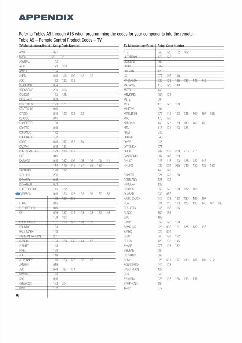
8/2/2019 AVR247om lores
http://slidepdf.com/reader/full/avr247om-lores 68/76
68
TV Manufacturer/Brand Setup Code Number
AIWA 027
A MARK 122 132
ADMIRAL 192
AKAI 123 160
AMPRO 164
ANAM 045 106 109 112 122
AOC 122 123 128
BLAUPUNKT 084
BROKSONIC 205 206
CANDLE 123 128
CAPEHART 059
CENTURION 123 171
CENTRONIC 045
CITIZEN 045 123 128 132
CLASSIC 045
CONCERTO 128
CONTEC 045
CORANDO 172
CORONADO 132
CRAIG 045 157 158 159
CROWN 045 132
CURTIS MATHES 123 128 132
CXC 045
DAEWOO 045 087 102 105 106 108 111
114 116 119 127 128 132
DAYTRON 128 132
DIGI LINK 200
DYNASTY 045DYNATECH 063
ELECTROHOME 115 132
EMERSON 045 123 128 132 139 157 158
159 162 205
FUNAI 045
FUTURETECH 045
GE 029 087 121 123 128 133 145
159 163
GOLDSTAR/LG 101 110 122 128 132
GRUNDIG 193
HALL MARK 128
HARMAN KARDON 201
HITACHI 123 128 132 144 147
INFINITY 148
INKEL 120
JBL 148
JC PENNEY 115 123 128 132 145
JENSEN 019
JVC 079 087 134
KAWASHO 173
KEC 045
KENWOOD 123 204
KMC 132
TV Manufacturer/Brand Setup Code Number
KTV 045 123 132 162
LLOYTRON 172 173
LODGENET 069
LOGIK 069
LUXMAN 128
LXI 077 145 148
MAGNAVOX 030 123 128 132 145 148
MARANTZ 115 123 148
MATSUI 148
MEMOREX 069 128
METZ 084
MGA 115 123 128
MINERVA 084
MITSUBISHI 077 115 123 128 160 167 168
MTC 175 176
NATIONAL 148 177 179 180 181 182
NEC 115 121 123 125
NIKEI 045
ONKING 045
ONWA 045
OPTONICA 077
ORION 207 208 209 210 211
PANASONIC 087 148 169
PHILCO 045 115 123 128 132 148
PHILIPS 033 034 035 036 123 128 132
145 148
PIONEER 024 123 128
PORTLAND 128 132PROSCAN 133
PROTON 059 122 128 132 165
QUASAR 032 087
RADIO SHACK 045 128 132 180 196 197
RCA 021 115 123 128 133 145 161 163
REALISTIC 045 167 196
RUNCO 152 153
SAA 183
SAMPO 059 123 128
SAMSUNG 020 022 124 128 132 145
SANYO 026 054
SCOTT 045 128 132
SEARS 128 132 145
SHARP 077 128 132
SIEMENS 084
SIGNATURE 069
SONY 028 031 117 130 136 194 212
SOUNDESIGN 045 128
SPECTRICON 122
SSS 045
SYLVANIA 025 123 128 145 148
SYMPHONIC 184
TANDY 077
APPENDIX
Refer to Tables A9 through A16 when programming the codes for your components into the remote.
Table A9 – Remote Control Product Codes – TV
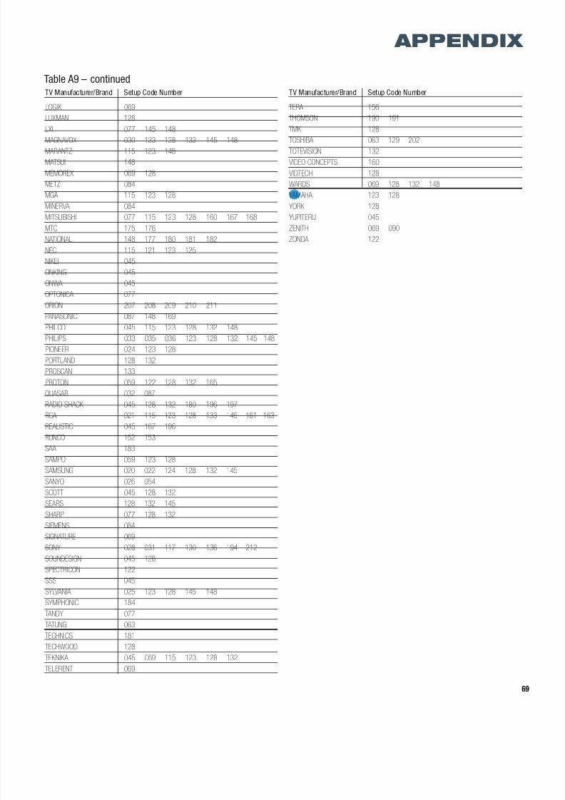
8/2/2019 AVR247om lores
http://slidepdf.com/reader/full/avr247om-lores 69/76
69
TV Manufacturer/Brand Setup Code Number
LOGIK 069
LUXMAN 128
LXI 077 145 148
MAGNAVOX 030 123 128 132 145 148MARANTZ 115 123 148
MATSUI 148
MEMOREX 069 128
METZ 084
MGA 115 123 128
MINERVA 084
MITSUBISHI 077 115 123 128 160 167 168
MTC 175 176
NATIONAL 148 177 180 181 182
NEC 115 121 123 125
NIKEI 045
ONKING 045
ONWA 045
OPTONICA 077
ORION 207 208 209 210 211
PANASONIC 087 148 169
PHILCO 045 115 123 128 132 148
PHILIPS 033 035 036 123 128 132 145 148
PIONEER 024 123 128
PORTLAND 128 132
PROSCAN 133
PROTON 059 122 128 132 165
QUASAR 032 087
RADIO SHACK 045 128 132 180 196 197
RCA 021 115 123 128 133 145 161 163
REALISTIC 045 167 196
RUNCO 152 153
SAA 183
SAMPO 059 123 128
SAMSUNG 020 022 124 128 132 145
SANYO 026 054
SCOTT 045 128 132
SEARS 128 132 145
SHARP 077 128 132
SIEMENS 084
SIGNATURE 069
SONY 028 031 117 130 136 194 212
SOUNDESIGN 045 128SPECTRICON 122
SSS 045
SYLVANIA 025 123 128 145 148
SYMPHONIC 184
TANDY 077
TATUNG 063
TECHNICS 181
TECHWOOD 128
TEKNIKA 045 069 115 123 128 132
TELERENT 069
TV Manufacturer/Brand Setup Code Number
TERA 156
THOMSON 190 191
TMK 128
TOSHIBA 063 129 202TOTEVISION 132
VIDEO CONCEPTS 160
VIDTECH 128
WARDS 069 128 132 148
YAMAHA 123 128
YORK 128
YUPITERU 045
ZENITH 069 090
ZONDA 122
APPENDIX
Table A9 – continued
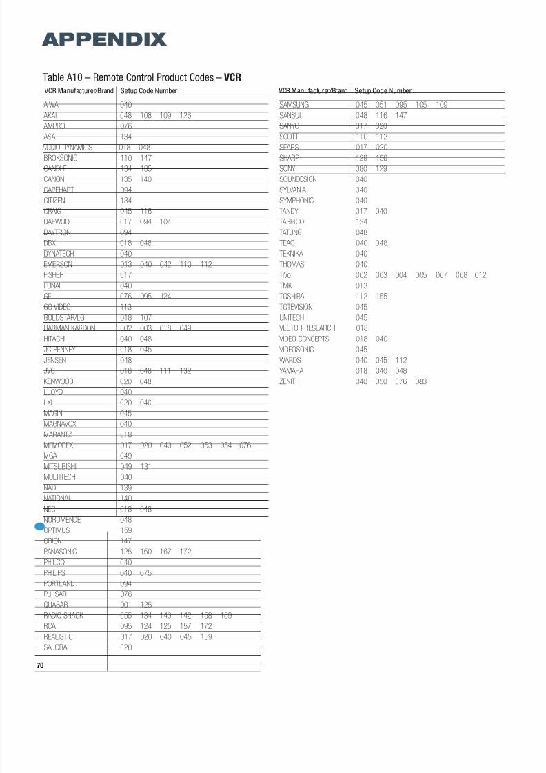
8/2/2019 AVR247om lores
http://slidepdf.com/reader/full/avr247om-lores 70/76
70
APPENDIX
VCR Manufacturer/Brand Setup Code Number
AIWA 040
AKAI 048 108 109 126
AMPRO 076
ASA 134 AUDIO DYNAMICS 018 048
BROKSONIC 110 147
CANDLE 134 135
CANON 135 140
CAPEHART 094
CITIZEN 134
CRAIG 045 116
DAEWOO 017 094 104
DAYTRON 094
DBX 018 048
DYNATECH 040
EMERSON 013 040 042 110 112
FISHER 017
FUNAI 040
GE 076 095 124
GO VIDEO 113
GOLDSTAR/LG 018 107
HARMAN KARDON 002 003 018 049
HITACHI 040 048
JC PENNEY 018 045
JENSEN 048
JVC 018 048 111 132
KENWOOD 020 048
LLOYD 040
LXI 020 040MAGIN 045
MAGNAVOX 040
MARANTZ 018
MEMOREX 017 020 040 052 053 054 076
MGA 049
MITSUBISHI 049 131
MULTITECH 040
NAD 139
NATIONAL 140
NEC 018 048
NORDMENDE 048
OPTIMUS 159
ORION 147PANASONIC 125 150 167 172
PHILCO 040
PHILIPS 040 075
PORTLAND 094
PULSAR 076
QUASAR 001 125
RADIO SHACK 055 134 140 142 158 159
RCA 095 124 125 157 172
REALISTIC 017 020 040 045 159
SALORA 020
VCR Manufacturer/Brand Setup Code Number
SAMSUNG 045 051 095 105 109
SANSUI 048 116 147
SANYO 017 020
SCOTT 110 112SEARS 017 020
SHARP 129 156
SONY 080 129
SOUNDESIGN 040
SYLVANIA 040
SYMPHONIC 040
TANDY 017 040
TASHICO 134
TATUNG 048
TEAC 040 048
TEKNIKA 040
THOMAS 040
TiVo 002 003 004 005 007 008 012
TMK 013
TOSHIBA 112 155
TOTEVISION 045
UNITECH 045
VECTOR RESEARCH 018
VIDEO CONCEPTS 018 040
VIDEOSONIC 045
WARDS 040 045 112
YAMAHA 018 040 048
ZENITH 040 050 076 083
Table A10 – Remote Control Product Codes – VCR

8/2/2019 AVR247om lores
http://slidepdf.com/reader/full/avr247om-lores 71/76
71
CD Manufacturer/Brand Setup Code Number
ADCOM 063 069
AIWA 072 111 118 156 170
AKAI 050 177 184
AUDIO TECHNICA 053 AUDIOACCESS 125
AUDIOFILE 211
BSR 044
CALIFORNIA AUDIO 109
CAPETRONIC 070
CARRERA 087
CARVER 136 140 141 143 144 145 185 186
CASIO 117 166
CLARINETTE 166
DENON 187 188 213
EMERSON 052 093 108
FISHER 055 095
FRABA 117
FUNAI 126
GE 164
GENEXXA 108
GOLDSTAR/LG 016 087
HAITAI 099 214
HARMAN KARDON 001 002 025 054 190
HITACHI 093
INKEL 216
JC PENNEY 098 147
JENSEN 153
JVC 176 195 196
KENWOOD 030 062 078 079 148 151 176178 181
LOTTE 108
LUXMAN 077 102
LXI 164
MAGNAVOX 039 113
MARANTZ 058 084 191 192 193
MCINTOSH 194
MCS 080 098
MITSUMI 152
MODULAIRE 166
NAD 013 074 197 198
NAKAMICHI 199 200 201
NEC 069NIKKO 053 055
ONKYO 037 038 045 046 171 175 202 203
OPTIMUS 065 089 091 092 099 104 212
PANASONIC 075 109 119 158 183 204
PHILIPS 039 138 149 209
PIONEER 071 094 100 112 123 131 161
162 215
PROTON 210
QUASAR 109
RADIO SHACK 126 166 213
CD Manufacturer/Brand Setup Code Number
RCA 024 081 093 150
RCX 169
REALISTIC 058 093 095 104 105 108 164 166
SANSUI 047 081 134 157 172SANYO 033 082 095
SCOTT 108
SHARP 058 105 114 151 159 167 180 181
SHERWOOD 003 041 058 105 133
SONY 103 115 116 118 132 139 163 205
206 207 208 212 217
SOUNDSTREAM 124
SYMPHONIC 059 110
TAEKWANG 177
TEAC 011 058 085 086 106 107 110 121
137 146 154
THETA DIGITAL 039
TOSHIBA 013 074 097 151 155 173
VECTOR RESEARCH 087
VICTOR 120 130
WARDS 095
YAMAHA 019 031 053 061 135 169
YORK 166
APPENDIX
Table A11 – Remote Control Product Codes – CD
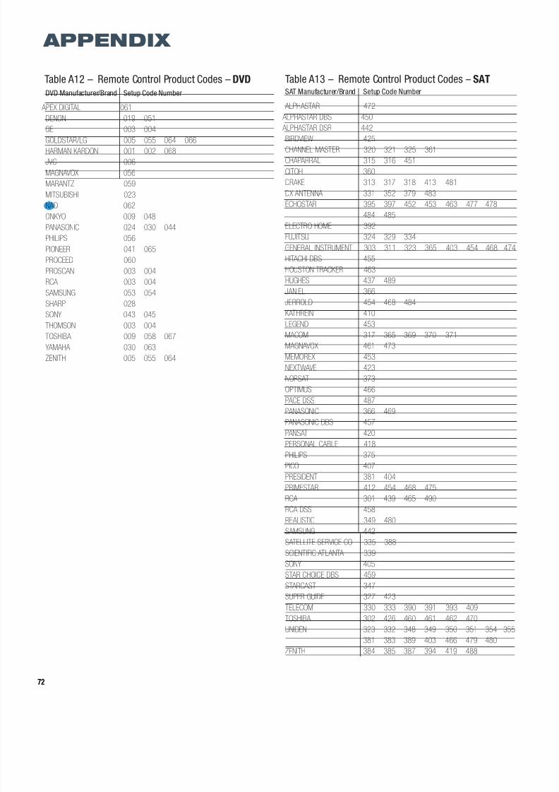
8/2/2019 AVR247om lores
http://slidepdf.com/reader/full/avr247om-lores 72/76
72
APPENDIX
Table A12 – Remote Control Product Codes – DVD
DVD Manufacturer/Brand Setup Code Number
APEX DIGITAL 061
DENON 019 051
GE 003 004
GOLDSTAR/LG 005 055 064 066HARMAN KARDON 001 002 068
JVC 006
MAGNAVOX 056
MARANTZ 059
MITSUBISHI 023
NAD 062
ONKYO 009 048
PANASONIC 024 030 044
PHILIPS 056
PIONEER 041 065
PROCEED 060
PROSCAN 003 004
RCA 003 004
SAMSUNG 053 054
SHARP 028
SONY 043 045
THOMSON 003 004
TOSHIBA 009 058 067
YAMAHA 030 063
ZENITH 005 055 064
SAT Manufacturer/Brand Setup Code Number
ALPHASTAR 472
ALPHASTAR DBS 450
ALPHASTAR DSR 442
BIRDVIEW 425CHANNEL MASTER 320 321 325 361
CHAPARRAL 315 316 451
CITOH 360
DRAKE 313 317 318 413 481
DX ANTENNA 331 352 379 483
ECHOSTAR 395 397 452 453 463 477 478
484 485
ELECTRO HOME 392
FUJITSU 324 329 334
GENERAL INSTRUMENT 303 311 323 365 403 454 468 474
HITACHI DBS 455
HOUSTON TRACKER 463
HUGHES 437 489
JANIEL 366
JERROLD 454 468 484
KATHREIN 410
LEGEND 453
MACOM 317 365 369 370 371
MAGNAVOX 461 473
MEMOREX 453
NEXTWAVE 423
NORSAT 373
OPTIMUS 466
PACE DSS 487
PANASONIC 366 469
PANASONIC DBS 457
PANSAT 420
PERSONAL CABLE 418
PHILIPS 375
PICO 407
PRESIDENT 381 404
PRIMESTAR 412 454 468 475
RCA 301 439 465 490
RCA DSS 458
REALISTIC 349 480
SAMSUNG 442
SATELLITE SERVICE CO 335 388
SCIENTIFIC ATLANTA 339SONY 405
STAR CHOICE DBS 459
STARCAST 347
SUPER GUIDE 327 423
TELECOM 330 333 390 391 393 409
TOSHIBA 302 426 460 461 462 470
UNIDEN 323 332 348 349 350 351 354 355
381 383 389 403 466 479 480
ZENITH 384 385 387 394 419 488
Table A13 – Remote Control Product Codes – SAT
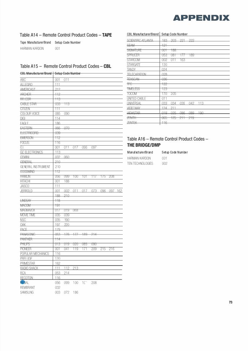
8/2/2019 AVR247om lores
http://slidepdf.com/reader/full/avr247om-lores 73/76
73
APPENDIX
Tape Manufacturer/Brand Setup Code Number
HARMAN KARDON 001
Table A15 – Remote Control Product Codes – CBL
CBL Manufacturer/Brand Setup Code Number
ABC 001 011
ALLEGRO 111
AMERICAST 212
ARCHER 112
BELCOR 113
CABLE STAR 033 113
CITIZEN 111
COLOUR VOICE 085 090
DIGI 114
EAGLE 186EASTERN 066 070
ELECTRICORD 039
EMERSON 112
FOCUS 116
G.I. 001 011 017 096 097
GC ELECTRONICS 113
GEMINI 032 060
GENERAL 210
GENERAL INSTRUMENT 210
GOODMIND 112
HAMLIN 056 099 100 101 117 175 208
HITACHI 001 188
JASCO 111
JERROLD 001 002 011 017 073 096 097 162
188 210
LINDSAY 118
MACOM 191
MAGNAVOX 017 019 068
MOVIE TIME 035 039
NSC 035 190
OAK 197 220
PACE 179
PANASONIC 053 176 177 189 214
PANTHER 114
PHILIPS 013 019 020 085 090
PIONEER 001 041 119 171 209 215 216
POPULAR MECHANICS 116
PRELUDE 120
PRIMESTAR 162
RADIO SHACK 111 112 213
RCA 053 214
RECOTON 116
REGAL 056 099 100 101 208
REMBRANT 032
SAMSUNG 003 072 186
Table A14 – Remote Control Product Codes – TAPE CBL Manufacturer/Brand Setup Code Number
SCIENTIFIC ATLANTA 183 203 221 222
SEAM 121
SIGNATURE 001 188
SPRUCER 053 081 177 189
STARCOM 002 011 163STARGATE 120
TANDY 024
TELECAPATION 028
TEXSCAN 036
TFC 122
TIMELESS 123
TOCOM 170 205
UNITED CABLE 011
UNIVERSAL 033 034 039 042 113
VIDEOWAY 124 211
VIEWSTAR 019 025 086 089 190
ZENITH 065 125 211 219
ZENTEK 116
Manufacturer/Brand Setup Code Number
HARMAN KARDON 001
TEN TECHNOLOGIES 002
Table A16 – Remote Control Product Codes –
THE BRIDGE/DMP

8/2/2019 AVR247om lores
http://slidepdf.com/reader/full/avr247om-lores 74/76
74
NOTES

8/2/2019 AVR247om lores
http://slidepdf.com/reader/full/avr247om-lores 75/76
NOTES

8/2/2019 AVR247om lores
http://slidepdf.com/reader/full/avr247om-lores 76/76