AVR : EE-303C - Emco Electronics · 1 Important Note : For AVR operations and other details, please...
12
(An ISO 9001:2008 Mfg. Co.) AVR : EE-303C with Communication (RS-232 & MODBUS) Instruction Manual EMCO ELECTRONICS Head Office : 302, Vasan Udyog Bhavan, Senapati Bapat Marg, Lower Parel (W), Mumbai – 400 013. Tel.: +91-22-2492 3183 / 2490 2283 Fax : +91-22-2495 1024 E-mail : [email protected] Factory : Unit No. 13, Kedarnath, Tungareshwar Indl. Complex No. 1, Sativali, Vasai (E), Dist - Thane. 401 208. Tel. : +91-250-2481 783 / 6481 782 Fax : +91-250-2481 087 E-mail : [email protected] South Office : 15, Wood Street, 1 st floor, Richmond Road, Bangalore – 560 025. Tel.: +91-80-2557 0215 Tel.Fax : +91-80-2556 6606 E-mail : [email protected] www.emcoelectronics.org
Transcript of AVR : EE-303C - Emco Electronics · 1 Important Note : For AVR operations and other details, please...
(An ISO 9001:2008 Mfg. Co.)
AVR : EE-303C
with Communication (RS-232 & MODBUS) Instruction Manual
EMCO ELECTRONICS
Head Office
: 302, Vasan Udyog Bhavan, Senapati Bapat Marg, Lower Parel (W), Mumbai – 400 013. Tel.: +91-22-2492 3183 / 2490 2283
Fax : +91-22-2495 1024 E-mail : [email protected]
Factory : Unit No. 13, Kedarnath, Tungareshwar Indl. Complex No. 1, Sativali, Vasai (E), Dist - Thane. 401 208. Tel. : +91-250-2481 783 / 6481 782
Fax : +91-250-2481 087 E-mail : [email protected]
South Office
: 15, Wood Street, 1st floor, Richmond Road, Bangalore – 560 025. Tel.: +91-80-2557 0215 Tel.Fax : +91-80-2556 6606 E-mail : [email protected]
www.emcoelectronics.org
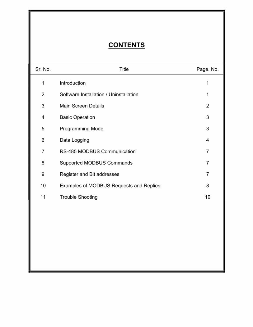
CONTENTS
Sr. No. Title Page. No. 1 Introduction 1 2 Software Installation / Uninstallation 1 3 Main Screen Details 2 4 Basic Operation 3 5 Programming Mode 3 6 Data Logging 4 7 RS-485 MODBUS Communication 7 8 Supported MODBUS Commands 7 9 Register and Bit addresses 7
10 Examples of MODBUS Requests and Replies 8
11 Trouble Shooting 10

1
Important Note :
For AVR operations and other details, please refer AVR EE-303 Instruction Manual. Introduction :
Emco’s AVR EE-303C has additional Communication facility. Supported Ports are RS-232 and RS-485 (for MODBUS protocol). RS-232 Communication is established via PC Software provided with the unit. All the variables such as PT, KV, Min, Max, Tap No. and Tap Count can be monitored simultaneously on the computer. LED’s indicating Under Voltage, Over Voltage and Control Fail conditions are also displayed on software. All the parameters such as Lower Setting, Raise Setting, Nominal Voltage, Kilo Volts, Under Voltage, Over Voltage, Timer 1, Timer 2, Control Fail Delay, Maximum Tap, Operating Mode and Control Mode can be simultaneously monitored. Minimum, Maximum and Tap Count recording can be reset individually or at once. In manual operating mode, Lower pulse and Raise pulse can be issued via software. Data logging can be enabled for Variables like Date, Time, PT Voltage, KV, Minimum, Maximum, Tap No., and Tap Count., Database can be searched with respect to all the variables except time. Also graph plotting of database can be done using ‘Search by Date’ in one click. MODBUS Communication is established using RS-485 port provided at the rear panel. All the variables can be monitored via MODBUS. LED’s indicating Under Voltage, Over Voltage and Control Fail conditions can be monitored. Also resetting of Minimum, Maximum and Tap Count can be done using MODBUS. Minimum System Configuration:
• IBM Compatible Pentium 4 Processor • 512MB RAM • 500MB of Harddisk Space
Software Installation :
Software installation is very easy. Just insert the CD labeled “AVR EE-303C Monitoring and Controlling Software” in the CD-Rom drive. This will automatically start the installation. Initially it checks for the required components. If ok then it starts the installation. If all the required components are not found then it starts installation of this missing components. During installation it first gives the warning about “Unknown Publisher” and asks whether you want to install it anyway. Click on the “Install” button. This will install the software. After the software is installed successfully, it automatically runs the program i.e. it opens the main screen for you as shown in figure 1. Software Uninstallation : Incase you need to uninstall the software, go to “Control Panel > Add Remove Software”, find the entry for “AVR EE-303”. Click on “Change/Remove”. This will start the uninstallation wizard. Select “Remove the application from this Computer.” and you are done. The software will get uninstalled.
2
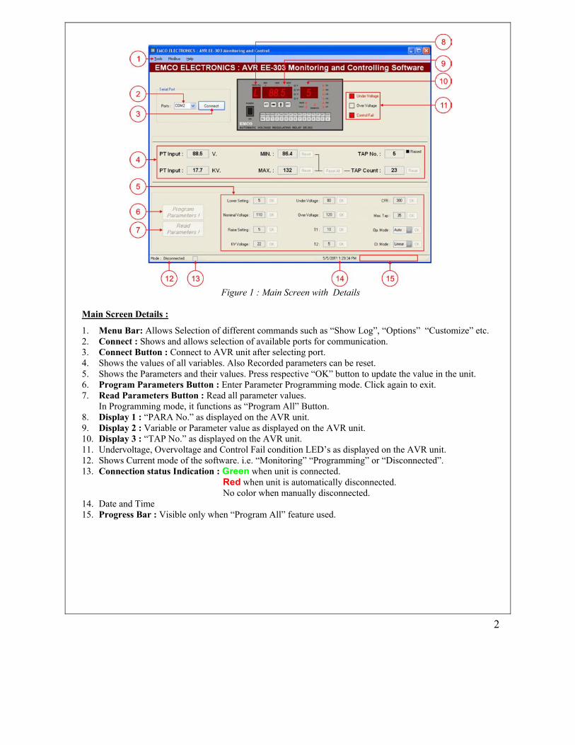
Figure 1 : Main Screen with Details
Main Screen Details : 1. Menu Bar: Allows Selection of different commands such as “Show Log”, “Options” “Customize” etc. 2. Connect : Shows and allows selection of available ports for communication. 3. Connect Button : Connect to AVR unit after selecting port. 4. Shows the values of all variables. Also Recorded parameters can be reset. 5. Shows the Parameters and their values. Press respective “OK” button to update the value in the unit. 6. Program Parameters Button : Enter Parameter Programming mode. Click again to exit. 7. Read Parameters Button : Read all parameter values.
In Programming mode, it functions as “Program All” Button. 8. Display 1 : “PARA No.” as displayed on the AVR unit. 9. Display 2 : Variable or Parameter value as displayed on the AVR unit. 10. Display 3 : “TAP No.” as displayed on the AVR unit. 11. Undervoltage, Overvoltage and Control Fail condition LED’s as displayed on the AVR unit. 12. Shows Current mode of the software. i.e. “Monitoring” “Programming” or “Disconnected”. 13. Connection status Indication : Green when unit is connected.
Red when unit is automatically disconnected. No color when manually disconnected.
14. Date and Time 15. Progress Bar : Visible only when “Program All” feature used.
3
Basic Operation : Starting the Program : Once the Setup is completed, to start the program, go to “Start Menu > All Programs > Emco Electronics > AVR EE-303”. This will bring up the main screen. To connect to the unit click “Connect” button. Once the unit is connected, it will read all the Variables, LED Conditions and Parameter values. Monitoring Mode : In Monitoring mode, Display 2 shows “PT Voltage” on LV side with parameter number “L” on Display 1. Display 3 shows the “Tap No.” as on AVR Monitoring mode monitors the following variables continuously :
1. PT Voltage 2. Primary side KV 3. Minimum Recorded Voltage (Resetable) 4. Maximum Recorded Voltage (Resetable) 5. Tap No. along with the status of last Tap Change. 6. Tap count (Resetable)
Note : Parameters are not updated automatically. Use “Read Parameters !” Button (point 7 in figure 1) to read the values of parameters (point 5 in figure 1).
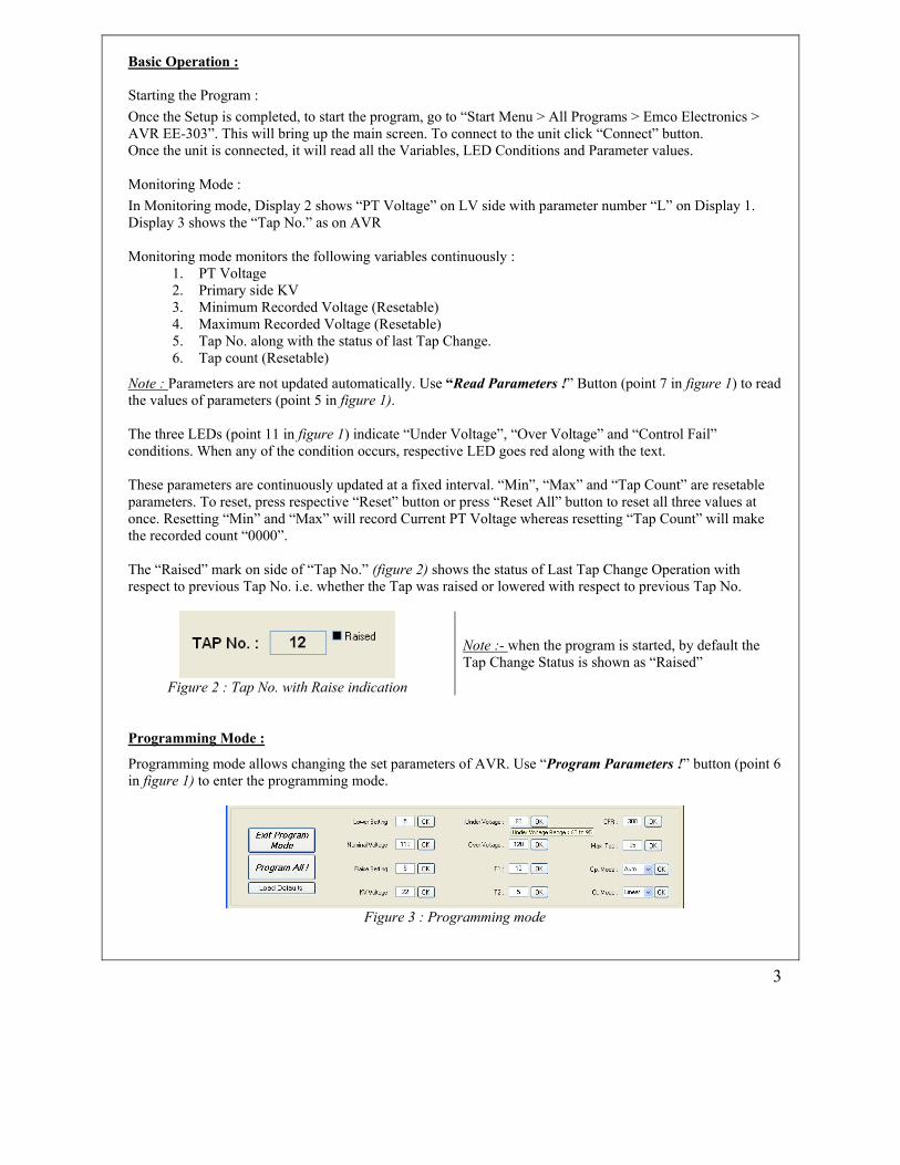
The three LEDs (point 11 in figure 1) indicate “Under Voltage”, “Over Voltage” and “Control Fail” conditions. When any of the condition occurs, respective LED goes red along with the text. These parameters are continuously updated at a fixed interval. “Min”, “Max” and “Tap Count” are resetable parameters. To reset, press respective “Reset” button or press “Reset All” button to reset all three values at once. Resetting “Min” and “Max” will record Current PT Voltage whereas resetting “Tap Count” will make the recorded count “0000”. The “Raised” mark on side of “Tap No.” (figure 2) shows the status of Last Tap Change Operation with respect to previous Tap No. i.e. whether the Tap was raised or lowered with respect to previous Tap No.
Figure 2 : Tap No. with Raise indication
Note :- when the program is started, by default the Tap Change Status is shown as “Raised”
Programming Mode :
Programming mode allows changing the set parameters of AVR. Use “Program Parameters !” button (point 6 in figure 1) to enter the programming mode.
Figure 3 : Programming mode

4
When in programming mode, the “Program Parameters !” button changes to “Exit Program Mode”, the “Read Parameters !” button changes to “Program All !” button and “Load Defaults” button is shown as in figure 3 above. Now the user can change the required parameters within its specified limits. If the entered value is out of the parameters specified limits then the control is locked to that parameter until and unless the correct value i.e. value within its limits is entered. Also a pop-up is displayed showing correct value range for that parameter. To know the limits of the parameters before entering the new value, hold the cursor on the value of that parameter. This will show a text message indicating the permissible range for that parameter as shown for “Under Voltage” parameter in the figure 3 above. “Program All !” button programs all the parameters simultaneously. “Load Defaults” button is used to load the default values of all parameters for programming. Closing the Program: To close the program, click on the “Disconnect” button if the program is connected to the unit. Then click red button on top-right of the window marked “X”. If program is closed without disconnecting from the unit, then it asks whether you really want to quit the program or just minimize it to system tray. If program is minimized to system tray, it disappears from the screen but the data logging (if enabled) works in the background whereas closing the program closes it completely i.e. it stops data logging also. Data Logging : By default, logging of parameters is disabled. To enable logging, check the “Enable Logging” by going to “Tools > Options > Enable Logging” and click it. Clicking on “Enable Logging” toggles between enable and disable logging. Note :- “Enable Logging” function is available on both windows i.e. Main window and Log window. The following Parameters are logged :
1. Date 2. Time 3. PT_Vg : PT Voltage 4. PT_KV : PT Voltage in KV 5. Min : Recorded Minimum Voltage 6. Max : Recorded Maximum Voltage 7. Tap No. : Current Tap Number 8. Tap Count : Recorded Tap Change Count To open the Log Window (figure 4), go to “Tools > Show Log” or press “Ctrl + Alt + L” on the key board. Log period and Log Interval: Log Period : No. of months for which the data will be saved in log file. Log Interval : No. of minutes after which a new entry will be added to log. To change the Log Period and Log Interval, go to “Tools > Customize > Logging Interval”. This will open a window where Log Period and Log Interval can be changed. By default Log Period is set to 1 month and Log Interval is set to 15 minute. The range for Log Period is 1 to 12 months and the range for Log Interval is 1 to 60 minutes.

5
Figure 4 : Log Window
Search : Search facility is available to search records based on different parameters (Figure 5). Default is “Search by Date”. Other search criteria includes search by “PT Voltage”, “KV”, “Min”, “Max”, “Tap No.” and “Tap Count”.
To display the records, click the “Show” button on log window. Now “Show” button changes to “Show All” button and clicking the “Show All” button displays all the records in the log file. Each search option except search by “Date” has two boxes for defining the range i.e. “From” and “To”. If search value is entered only in “From” box and “To” is left blank then all the records greater then “From” value with respect to search parameter are searched and displayed. Similarly, if only “To” value is entered and “From” is left blank, then all records lesser then “To” value are searched. If both the values are entered then that range of records are searched. When both are blank all records are displayed.
Figure 5 : Search menu
6
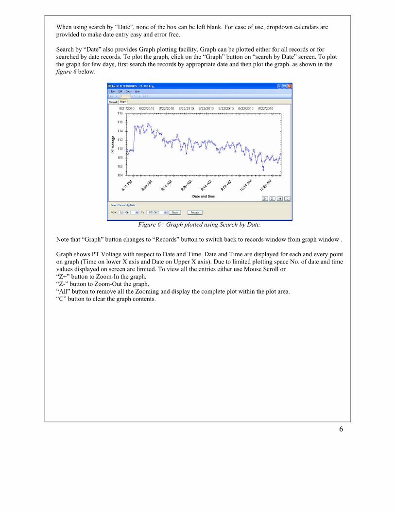
When using search by “Date”, none of the box can be left blank. For ease of use, dropdown calendars are provided to make date entry easy and error free. Search by “Date” also provides Graph plotting facility. Graph can be plotted either for all records or for searched by date records. To plot the graph, click on the “Graph” button on “search by Date” screen. To plot the graph for few days, first search the records by appropriate date and then plot the graph. as shown in the figure 6 below.
Figure 6 : Graph plotted using Search by Date.
Note that “Graph” button changes to “Records” button to switch back to records window from graph window . Graph shows PT Voltage with respect to Date and Time. Date and Time are displayed for each and every point on graph (Time on lower X axis and Date on Upper X axis). Due to limited plotting space No. of date and time values displayed on screen are limited. To view all the entries either use Mouse Scroll or “Z+” button to Zoom-In the graph. “Z-” button to Zoom-Out the graph. “All” button to remove all the Zooming and display the complete plot within the plot area. “C” button to clear the graph contents.
7
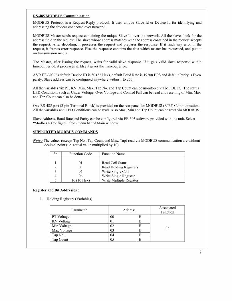
RS-485 MODBUS Communication
MODBUS Protocol is a Request-Reply protocol. It uses unique Slave Id or Device Id for identifying and addressing the devices connected over network. MODBUS Master sends request containing the unique Slave Id over the network. All the slaves look for the address field in the request. The slave whose address matches with the address contained in the request accepts the request. After decoding, it processes the request and prepares the response. If it finds any error in the request, it frames error response. Else the response contains the data which master has requested, and puts it on transmission media. The Master, after issuing the request, waits for valid slave response. If it gets valid slave response within timeout period, it processes it. Else it gives the Timeout error. AVR EE-303C’s default Device ID is 50 (32 Hex), default Baud Rate is 19200 BPS and default Parity is Even parity. Slave address can be configured anywhere within 1 to 255. All the variables viz PT, KV, Min, Max, Tap No. and Tap Count can be monitored via MODBUS. The status LED Conditions such as Under Voltage, Over Voltage and Control Fail can be read and resetting of Min, Max and Tap Count can also be done. One RS-485 port (3-pin Terminal Block) is provided on the rear panel for MODBUS (RTU) Communication. All the variables and LED Conditions can be read. Also Max, Min and Tap Count can be reset via MODBUS Slave Address, Baud Rate and Parity can be configured via EE-303 software provided with the unit. Select “Modbus > Configure” from menu bar of Main window. SUPPORTED MODBUS COMMANDS Note : The values (except Tap No., Tap Count and Max. Tap) read via MODBUS communication are without
decimal point (i.e. actual value multiplied by 10).
Sr. Function Code Function Name
1 01 Read Coil Status 2 03 Read Holding Registers 3 05 Write Single Coil 4 06 Write Single Register 5 16 (10 Hex) Write Multiple Register
Register and Bit Addresses :
1. Holding Registers (Variables)
Parameter Address Associated Function
PT Voltage 00 H KV Voltage 01 H Min Voltage 02 H Max Voltage 03 H Tap No. 04 H Tap Count 05 H
03

8
2. Bit Addresses (Variables)
Bit Address Associated Function
Under Voltage (Read only) 00 H Over Voltage (Read only) 01 H Control Fail Indication (Read only) 02 H
01
Reset Minimum (Write only) 03 H 05 Reset Maximum (Write only) 04 H 05 Reset Tap Count (Write only) 05 H 05
3. Holding Registers (Parameters)
Parameter Address Associated Functions
Lower Setting 06 H 06 Nominal Voltage 07 H 06 Raise Setting 08 H 06 Primary Voltage (KV) 09 H 06 Under Voltage 0A H 06 Over Voltage 0B H 06 Timer 1 0C H 06 Timer 2 0D H 06 Control Fail delay 0E H 06 Maximum Tap 0F H
03
06
16
4. Bit Addresses (Parameters)
Bit Address Associated Function
Auto / Manual Mode 00 H Linear / Integral 01 H 01 05 -
Examples of MODBUS Requests and Replies : Example 1a - Read Holding Register Request (for reading all the variables) Field Name Example (Hex) Slave Address 32 Function 03 Starting Address High 00 Starting Address Low 00 Number of Registers High 00 Number of Registers Low 06
9
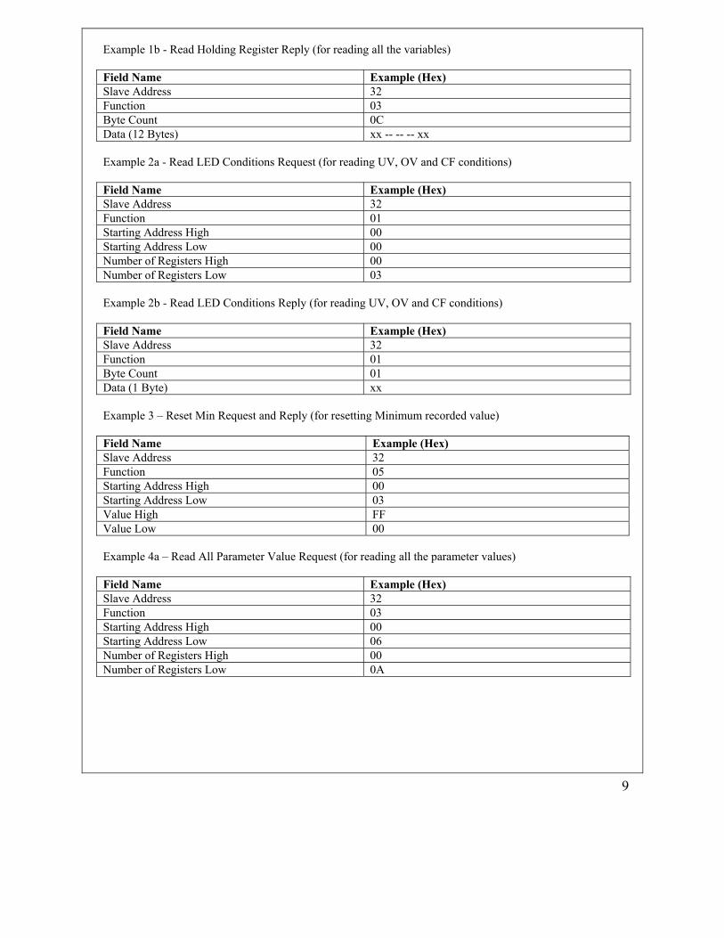
Example 1b - Read Holding Register Reply (for reading all the variables) Field Name Example (Hex) Slave Address 32 Function 03 Byte Count 0C Data (12 Bytes) xx -- -- -- xx Example 2a - Read LED Conditions Request (for reading UV, OV and CF conditions) Field Name Example (Hex) Slave Address 32 Function 01 Starting Address High 00 Starting Address Low 00 Number of Registers High 00 Number of Registers Low 03 Example 2b - Read LED Conditions Reply (for reading UV, OV and CF conditions) Field Name Example (Hex) Slave Address 32 Function 01 Byte Count 01 Data (1 Byte) xx Example 3 – Reset Min Request and Reply (for resetting Minimum recorded value) Field Name Example (Hex) Slave Address 32 Function 05 Starting Address High 00 Starting Address Low 03 Value High FF Value Low 00 Example 4a – Read All Parameter Value Request (for reading all the parameter values) Field Name Example (Hex) Slave Address 32 Function 03 Starting Address High 00 Starting Address Low 06 Number of Registers High 00 Number of Registers Low 0A

10
Example 4b – Read All Parameter Value Reply (for reading all the parameter values) Field Name Example (Hex) Slave Address 32 Function 03 Byte Count 14 Data (20 Bytes) xx -- -- -- xx Error Check Low xx Error Check High xx Example 5 – Write Lower setting Value Request and Reply (for Writing single parameter) Field Name Example (Hex) Slave Address 32 Function 06 Starting Address High 00 Starting Address Low 06 Data Value High 00 Data Value Low 32 Example 6a – Write All Parameter Value Request (for Writing all the parameter values) Field Name Example (Hex) Slave Address 32 Function 10 Starting Address High 00 Starting Address Low 06 Number of Registers High 00 Number of Registers Low 0A No. of bytes 14 Data (20 Bytes) xx -- -- -- xx Example 6b – Write All Parameter Value Reply (for Writing all the parameter values) Field Name Example (Hex) Slave Address 32 Function 10 Starting Address High 00 Starting Address Low 06 Number of Registers High 00 Number of Registers Low 0A Trouble Shooting
1. Check for connections. Check that all “A’s” are connected together; Check all “B’s” are connected together, and all “Gnd’s” are connected together.
2. Start with a simple network, one Master one Slave and check whether communication succeeds. 3. Make sure that each instrument has a unique address. 4. Check that MODBUS mode is set to RTU. 5. Check that Serial parameters (Baud Rate and Parity) are correctly configured.