AvnTEmE BEddEd SpEcificATion. · AvnTEmE BEddEd SpEcificATion. ... (National Marine Electronics...
12
Avnet Embedded. Support Around The Board ™ www.avnet-embedded.eu AvnET EmBEddEd SpEcificATion. datasheet Navman Wireless GPS3260/GPS3261
Transcript of AvnTEmE BEddEd SpEcificATion. · AvnTEmE BEddEd SpEcificATion. ... (National Marine Electronics...

Avnet Embedded. Support Around The Board™
www.avnet-embedded.eu
AvnET EmBEddEd SpEcificATion.
datasheet Navman WirelessGPS3260/GPS3261
LA000665B © 2008 Navman Wireless OEM Solutions. All rights reserved. Proprietary information and specifications subject to change without notice.
Related documents• GPS3260/GPS3261 xLP Product brief
LA000664
• Navman NMEA reference manual MN000315
• SiRF Binary Protocol reference manual
GPS3260/GPS3261Extra Low Power
Smart Sensor xLP Series
Data Sheet

LA000665B © 2008 Navman Wireless OEM Solutions. All rights reserved. Proprietary information and specifications subject to change without notice.
Contents1.0 Introduction ....................................................................................................... 42.0 Technical description ....................................................................................... 4
2.1 Product applications ..................................................................................................... 4
2.2 Physical characteristics ................................................................................................ 4
2.3 Mechanical specification .............................................................................................. 42.3.1 Physical dimensions and pin out assignments ..................................................... 42.3.2 Weight .................................................................................................................. 4
2.4 External mounting ........................................................................................................ 5
2.5 Connectors ................................................................................................................... 5
2.6 Environmental .............................................................................................................. 5
2.7 Compliances ................................................................................................................. 5
3.0 Performance characteristics ...........................................................................53.1 TTFF (Time To First Fix) ............................................................................................... 5
3.1.1 Hot start ................................................................................................................ 53.1.2 Warm start ............................................................................................................ 53.1.3 Cold start .............................................................................................................. 5
3.2 Acquisition times .......................................................................................................... 6
3.3 LED indicator ................................................................................................................ 6
3.4 Power management ..................................................................................................... 63.4.1 Adaptive TricklePower .......................................................................................... 6
3.5 Differential aiding ......................................................................................................... 63.5.1 Satellite Based Augmentation Systems (SBAS) ................................................... 6
3.7 Sensitivity ..................................................................................................................... 7
3.8 Dynamic constraints ..................................................................................................... 7
3.9 Position and velocity accuracy ..................................................................................... 7
4.0 Electrical requirements ....................................................................................74.1 Power consumption ...................................................................................................... 7
5.0 Software interface ............................................................................................ 85.1 NMEA output messages ............................................................................................... 8
5.1.1 Proprietary NMEA messages ............................................................................... 85.1.2 Proprietary NMEA input messages ...................................................................... 8
6.0 Product handling............................................................................................... 96.1 Packaging and delivery ................................................................................................ 9
6.4 Safety ........................................................................................................................... 9
6.5 Disposal ....................................................................................................................... 9
7.0 Ordering information ........................................................................................ 98.0 Glossary and acronyms ...................................................................................9
FiguresFigure 2-1 Physical dimensions .......................................................................................... 4
Figure 3-1 LED indicator duty cycle ................................................................................... 6

LA000665B © 2008 Navman Wireless OEM Solutions. All rights reserved. Proprietary information and specifications subject to change without notice.
TablesTable 3-1: Acquisition times at –125 dBm and –140 dBm ................................................... 6
Table 3-2: Sensitivity .......................................................................................................... 7
Table 3-3: Position and velocity accuracy .......................................................................... 7
Table 4-1: Power consumption (continuous mode) ............................................................. 7
Table 5-1: Default NMEA messages .................................................................................. 8
Table 7-1: Ordering information .......................................................................................... 9
�LA000665B © 2008 Navman Wireless OEM Solutions. All rights reserved. Proprietary information and specifications subject to change without notice.
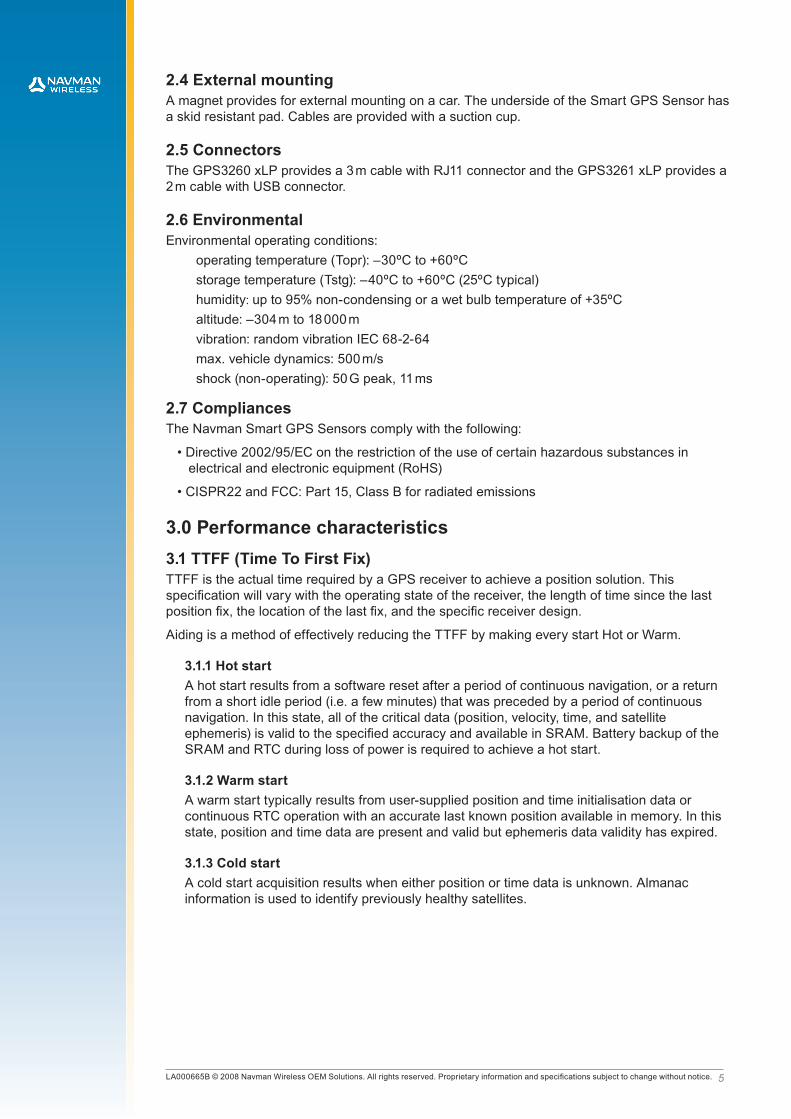
49 max 3000 ± 50 (RJ11) , 2000 ± 50 (USB)
Ø 25
Ø 25
41 max
14.1 max
USB
RJ11
6
1
1234
1: VBUS2: D-3: D+4: GND
1: NC 4: TX2: GND 5: VDD3: RX 6: NC
1.0 IntroductionNavman’s Extra Low Power Smart GPS Sensor is a tethered, fully integrated GPS antenna and high performance receiver that easily brings location capabilities to almost any platform. The GPS3260 xLP series includes a 20-channel ultra-high sensitivity receiver based on SiRFstar III technology, providing the fastest TTFF (Time to First Fix) possible in challenging environments such as urban canyons or dense foliage, and in all weather conditions.
2.0 Technical descriptionThe 20-channel architecture with more than 200 000 effective correlators provides rapid TTFF under all start-up conditions. Acquisition is guaranteed under all conditions due to higher sensitivity.
2.1 Product applicationsThe Extra Low Power Smart GPS Sensor is especially suitable for applications where rapid TTFF and operation under low signal levels are primary requirements. The module offers high performance and maximum flexibility in a wide range of OEM configurations.
Supporting advanced power management modes, SBAS and a variety of user selectable Datums the GPS3260 xLP Series provides the perfect plug and play GPS solution for automotive, marine, scientific, industrial, commercial, leisure and battery powered applications requiring ultimate navigation.
2.2 Physical characteristicsThe Smart GPS xLP Sensor is a complete GPS receiver within an enclosed housing that is waterproof to IPx7.
2.3 Mechanical specification2.3.1 Physical dimensions and pin out assignments
Dimensions in mm:
Figure 2-1: Physical dimensions
2.3.2 WeightTotal weight: 96 g max
�LA000665B © 2008 Navman Wireless OEM Solutions. All rights reserved. Proprietary information and specifications subject to change without notice.
2.4 External mountingA magnet provides for external mounting on a car. The underside of the Smart GPS Sensor has a skid resistant pad. Cables are provided with a suction cup.
2.5 ConnectorsThe GPS3260 xLP provides a 3 m cable with RJ11 connector and the GPS3261 xLP provides a 2 m cable with USB connector.
2.6 EnvironmentalEnvironmental operating conditions:
operating temperature (Topr): –30ºC to +60ºCstorage temperature (Tstg): –40ºC to +60ºC (25ºC typical)humidity: up to 95% non-condensing or a wet bulb temperature of +35ºCaltitude: –304 m to 18 000 mvibration: random vibration IEC 68-2-64max. vehicle dynamics: 500 m/sshock (non-operating): 50 G peak, 11 ms
2.7 CompliancesThe Navman Smart GPS Sensors comply with the following:
• Directive 2002/95/EC on the restriction of the use of certain hazardous substances in electrical and electronic equipment (RoHS)
• CISPR22 and FCC: Part 15, Class B for radiated emissions
3.0 Performance characteristics3.1 TTFF (Time To First Fix)TTFF is the actual time required by a GPS receiver to achieve a position solution. This specification will vary with the operating state of the receiver, the length of time since the last position fix, the location of the last fix, and the specific receiver design.
Aiding is a method of effectively reducing the TTFF by making every start Hot or Warm.
3.1.1 Hot startA hot start results from a software reset after a period of continuous navigation, or a return from a short idle period (i.e. a few minutes) that was preceded by a period of continuous navigation. In this state, all of the critical data (position, velocity, time, and satellite ephemeris) is valid to the specified accuracy and available in SRAM. Battery backup of the SRAM and RTC during loss of power is required to achieve a hot start.
3.1.2 Warm startA warm start typically results from user-supplied position and time initialisation data or continuous RTC operation with an accurate last known position available in memory. In this state, position and time data are present and valid but ephemeris data validity has expired.
3.1.3 Cold startA cold start acquisition results when either position or time data is unknown. Almanac information is used to identify previously healthy satellites.
�LA000665B © 2008 Navman Wireless OEM Solutions. All rights reserved. Proprietary information and specifications subject to change without notice.
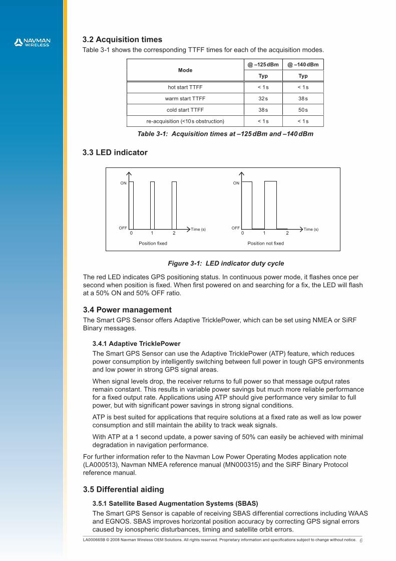
3.2 Acquisition timesTable 3-1 shows the corresponding TTFF times for each of the acquisition modes.
Mode@ –125 dBm @ –140 dBm
Typ Typ
hot start TTFF < 1 s < 1 s
warm start TTFF 32 s 38 s
cold start TTFF 38 s 50 s
re-acquisition (<10 s obstruction) < 1 s < 1 s
Table 3-1: Acquisition times at –125 dBm and –140 dBm
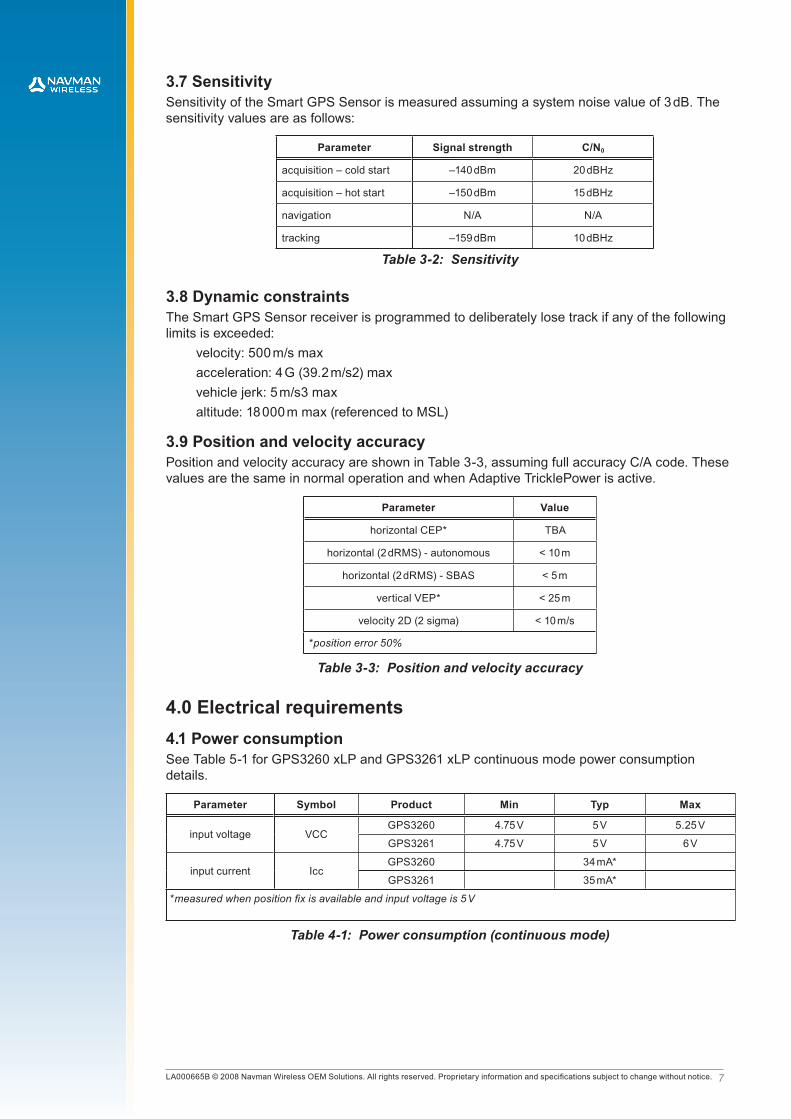
3.3 LED indicator
0 1Time (s)
2OFF
ON
Position fixed
0 1Time (s)
2OFF
ON
Position not fixed
Figure 3-1: LED indicator duty cycle
The red LED indicates GPS positioning status. In continuous power mode, it flashes once per second when position is fixed. When first powered on and searching for a fix, the LED will flash at a 50% ON and 50% OFF ratio.
3.4 Power managementThe Smart GPS Sensor offers Adaptive TricklePower, which can be set using NMEA or SiRF Binary messages.
3.4.1 Adaptive TricklePowerThe Smart GPS Sensor can use the Adaptive TricklePower (ATP) feature, which reduces power consumption by intelligently switching between full power in tough GPS environments and low power in strong GPS signal areas.
When signal levels drop, the receiver returns to full power so that message output rates remain constant. This results in variable power savings but much more reliable performance for a fixed output rate. Applications using ATP should give performance very similar to full power, but with significant power savings in strong signal conditions.
ATP is best suited for applications that require solutions at a fixed rate as well as low power consumption and still maintain the ability to track weak signals.
With ATP at a 1 second update, a power saving of 50% can easily be achieved with minimal degradation in navigation performance.
For further information refer to the Navman Low Power Operating Modes application note (LA000513), Navman NMEA reference manual (MN000315) and the SiRF Binary Protocol reference manual.
3.5 Differential aiding3.5.1 Satellite Based Augmentation Systems (SBAS)The Smart GPS Sensor is capable of receiving SBAS differential corrections including WAAS and EGNOS. SBAS improves horizontal position accuracy by correcting GPS signal errors caused by ionospheric disturbances, timing and satellite orbit errors.
�LA000665B © 2008 Navman Wireless OEM Solutions. All rights reserved. Proprietary information and specifications subject to change without notice.
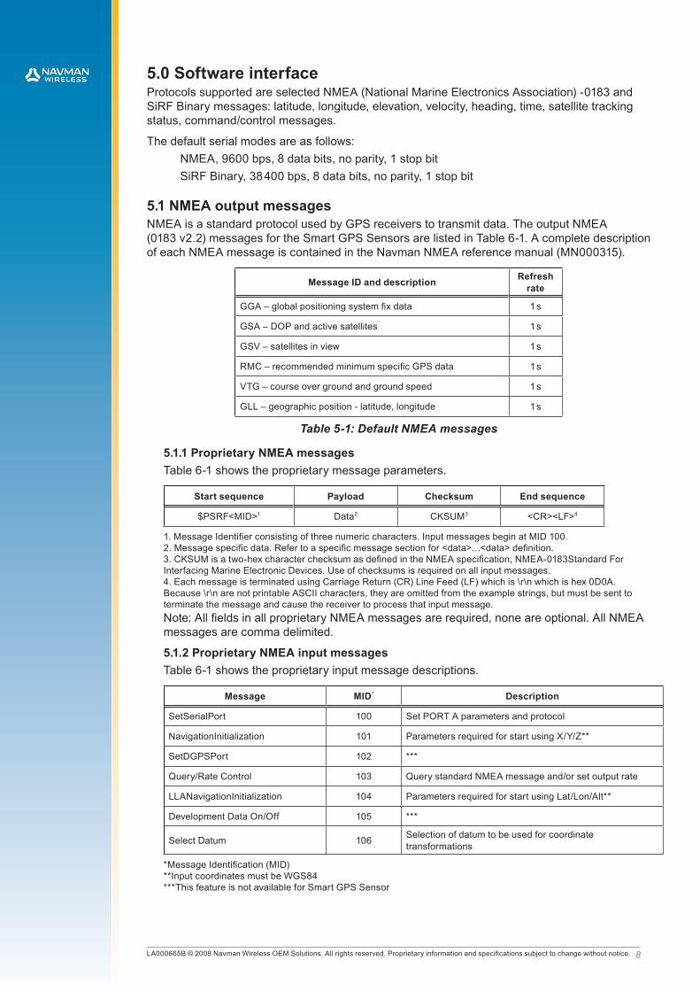
3.7 SensitivitySensitivity of the Smart GPS Sensor is measured assuming a system noise value of 3 dB. The sensitivity values are as follows:
Parameter Signal strength C/N0
acquisition – cold start –140 dBm 20 dBHz
acquisition – hot start –150 dBm 15 dBHz
navigation N/A N/A
tracking –159 dBm 10 dBHz
Table 3-2: Sensitivity
3.8 Dynamic constraintsThe Smart GPS Sensor receiver is programmed to deliberately lose track if any of the following limits is exceeded:
velocity: 500 m/s maxacceleration: 4 G (39.2 m/s2) maxvehicle jerk: 5 m/s3 maxaltitude: 18 000 m max (referenced to MSL)
3.9 Position and velocity accuracyPosition and velocity accuracy are shown in Table 3-3, assuming full accuracy C/A code. These values are the same in normal operation and when Adaptive TricklePower is active.
Parameter Value
horizontal CEP* TBA
horizontal (2 dRMS) - autonomous < 10 m
horizontal (2 dRMS) - SBAS < 5 m
vertical VEP* < 25 m
velocity 2D (2 sigma) < 10 m/s
*position error �0%
Table 3-3: Position and velocity accuracy
4.0 Electrical requirements4.1 Power consumptionSee Table 5-1 for GPS3260 xLP and GPS3261 xLP continuous mode power consumption details.
Parameter Symbol Product Min Typ Max
input voltage VCCGPS3260 4.75 V 5 V 5.25 V
GPS3261 4.75 V 5 V 6 V
input current IccGPS3260 34 mA*
GPS3261 35 mA*
*measured when position fix is available and input voltage is 5 V
Table 4-1: Power consumption (continuous mode)
�LA000665B © 2008 Navman Wireless OEM Solutions. All rights reserved. Proprietary information and specifications subject to change without notice.
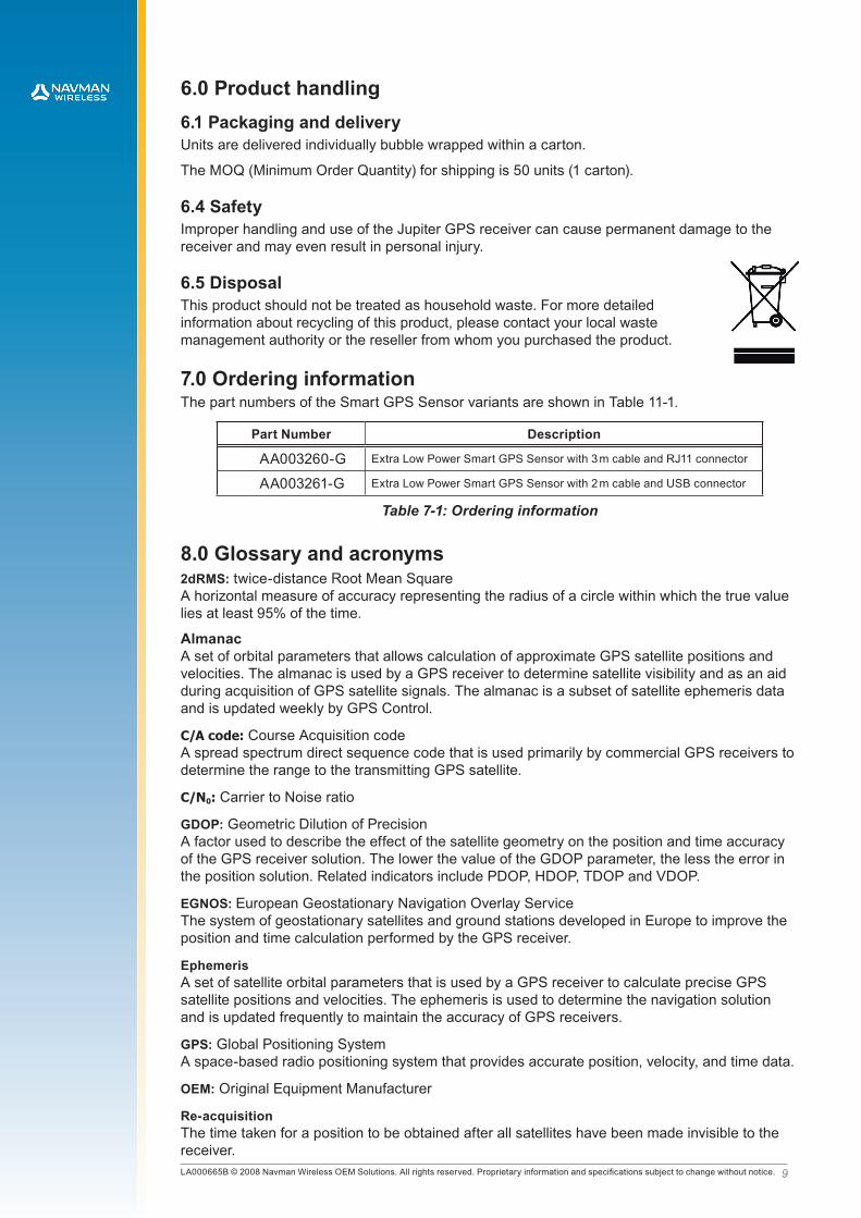
5.0 Software interfaceProtocols supported are selected NMEA (National Marine Electronics Association) -0183 and SiRF Binary messages: latitude, longitude, elevation, velocity, heading, time, satellite tracking status, command/control messages.
The default serial modes are as follows:NMEA, 9600 bps, 8 data bits, no parity, 1 stop bitSiRF Binary, 38 400 bps, 8 data bits, no parity, 1 stop bit
5.1 NMEA output messagesNMEA is a standard protocol used by GPS receivers to transmit data. The output NMEA (0183 v2.2) messages for the Smart GPS Sensors are listed in Table 6-1. A complete description of each NMEA message is contained in the Navman NMEA reference manual (MN000315).
Message ID and description Refresh rate
GGA – global positioning system fix data 1 s
GSA – DOP and active satellites 1 s
GSV – satellites in view 1 s
RMC – recommended minimum specific GPS data 1 s
VTG – course over ground and ground speed 1 s
GLL – geographic position - latitude, longitude 1 s
Table 5-1: Default NMEA messages
5.1.1 Proprietary NMEA messagesTable 6-1 shows the proprietary message parameters.
Start sequence Payload Checksum End sequence
$PSRF<MID>1 Data2 CKSUM3 <CR><LF>4
1. Message Identifier consisting of three numeric characters. Input messages begin at MID 100.2. Message specific data. Refer to a specific message section for <data>…<data> definition.3. CKSUM is a two-hex character checksum as defined in the NMEA specification, NMEA-0183Standard For Interfacing Marine Electronic Devices. Use of checksums is required on all input messages.4. Each message is terminated using Carriage Return (CR) Line Feed (LF) which is \r\n which is hex 0D0A. Because \r\n are not printable ASCII characters, they are omitted from the example strings, but must be sent to terminate the message and cause the receiver to process that input message.Note: All fields in all proprietary NMEA messages are required, none are optional. All NMEA messages are comma delimited.
5.1.2 Proprietary NMEA input messagesTable 6-1 shows the proprietary input message descriptions.
Message MID* Description
SetSerialPort 100 Set PORT A parameters and protocol
NavigationInitialization 101 Parameters required for start using X/Y/Z**
SetDGPSPort 102 ***
Query/Rate Control 103 Query standard NMEA message and/or set output rate
LLANavigationInitialization 104 Parameters required for start using Lat/Lon/Alt**
Development Data On/Off 105 ***
Select Datum 106 Selection of datum to be used for coordinate transformations
*Message Identification (MID)**Input coordinates must be WGS84***This feature is not available for Smart GPS Sensor
�LA000665B © 2008 Navman Wireless OEM Solutions. All rights reserved. Proprietary information and specifications subject to change without notice.
6.0 Product handling6.1 Packaging and deliveryUnits are delivered individually bubble wrapped within a carton.
The MOQ (Minimum Order Quantity) for shipping is 50 units (1 carton).
6.4 SafetyImproper handling and use of the Jupiter GPS receiver can cause permanent damage to the receiver and may even result in personal injury.
6.5 DisposalThis product should not be treated as household waste. For more detailed information about recycling of this product, please contact your local waste management authority or the reseller from whom you purchased the product.
7.0 Ordering informationThe part numbers of the Smart GPS Sensor variants are shown in Table 11-1.
Part Number Description
AA003260-G Extra Low Power Smart GPS Sensor with 3 m cable and RJ11 connector
AA003261-G Extra Low Power Smart GPS Sensor with 2 m cable and USB connector
Table 7-1: Ordering information
8.0 Glossary and acronyms2dRMS: twice-distance Root Mean Square A horizontal measure of accuracy representing the radius of a circle within which the true value lies at least 95% of the time.
Almanac A set of orbital parameters that allows calculation of approximate GPS satellite positions and velocities. The almanac is used by a GPS receiver to determine satellite visibility and as an aid during acquisition of GPS satellite signals. The almanac is a subset of satellite ephemeris data and is updated weekly by GPS Control.
C/A code: Course Acquisition code A spread spectrum direct sequence code that is used primarily by commercial GPS receivers to determine the range to the transmitting GPS satellite.
C/N0: Carrier to Noise ratio
GDOP: Geometric Dilution of Precision A factor used to describe the effect of the satellite geometry on the position and time accuracy of the GPS receiver solution. The lower the value of the GDOP parameter, the less the error in the position solution. Related indicators include PDOP, HDOP, TDOP and VDOP.
EGNOS: European Geostationary Navigation Overlay Service The system of geostationary satellites and ground stations developed in Europe to improve the position and time calculation performed by the GPS receiver.
EphemerisA set of satellite orbital parameters that is used by a GPS receiver to calculate precise GPS satellite positions and velocities. The ephemeris is used to determine the navigation solution and is updated frequently to maintain the accuracy of GPS receivers.
GPS: Global Positioning System A space-based radio positioning system that provides accurate position, velocity, and time data.
OEM: Original Equipment Manufacturer
Re-acquisition The time taken for a position to be obtained after all satellites have been made invisible to the receiver.
10LA000665B © 2008 Navman Wireless OEM Solutions. All rights reserved. Proprietary information and specifications subject to change without notice.
SBAS: Satellite Based Augmentation System Any system that uses a network of geostationary satellites and ground stations to improve the performance of a Global Navigation Satellite System (GNSS). Current examples are EGNOS and WAAS.
SRAM: Static Random Access Memory
SAW filter: Surface Acoustic Wave filter
WAAS: Wide Area Augmentation System The system of satellites and ground stations developed by the FAA (Federal Aviation Administration) that provides GPS signal corrections. WAAS satellite coverage is currently only available in North America.
© 2008 Navman Wireless OEM Solutions. All Rights Reserved.
SiRF and SiRF logo are registered trademarks of SiRF Technology, Inc. SiRFstar, SiRFLoc, Push-to-Fix, and Trickle-Power are trademarks of SiRF Technology, Inc. All other trademarks mentioned in this document are property of their respective owners.
Information in this document is provided in connection with Navman Wireless OEM Solutions(‘Navman’) products. These materials are provided by Navman as a service to its customers and may be used for informational purposes only. Navman assumes no responsibility for errors or omissions in these materials. Navman may make changes to specifica-tions and product descriptions at any time, without notice. Navman makes no commitment to update the information and shall have no responsibility whatsoever for conflicts or incompatibilities arising from future changes to its specifications and product descriptions. No license, express or implied, by estoppel or otherwise, to any intellectual property rights is granted by this document. Except as provided in Navman’s Terms and Conditions of Sale for such products, Navman assumes no liability whatsoever.
THESE MATERIALS ARE PROVIDED ‘AS IS’ WITHOUT WARRANTY OF ANY KIND, EITHER EXPRESSED OR IMPLIED, RELATING TO SALE AND/OR USE OF NAVMAN PRODUCTS INCLUDING LIABILITY OR WARRANTIES RELATING TO FITNESS FOR A PARTICULAR PURPOSE, CONSEQUENTIAL OR INCIDENTAL DAMAGES, MER-CHANTABILITY, OR INFRINGEMENT OF ANY PATENT, COPYRIGHT OR OTHER INTELLECTUAL PROPERTY RIGHT. NAVMAN FURTHER DOES NOT WARRANT THE ACCURACY OR COMPLETENESS OF THE INFORMATION, TEXT, GRAPHICS OR OTHER ITEMS CONTAINED WITHIN THESE MATERIALS. NAVMAN SHALL NOT BE LIABLE FOR ANY SPECIAL, INDIRECT, INCIDENTAL, OR CONSEQUENTIAL DAMAGES, INCLUDING WITHOUT LIMITA-TION, LOST REVENUES OR LOST PROFITS, WHICH MAY RESULT FROM THE USE OF THESE MATERIALS.
Navman products are not intended for use in medical, lifesaving or life sustaining applications. Navman customers using or selling Navman products for use in such applications do so at their own risk and agree to fully indemnify Navman for any damages resulting from such improper use or sale. Product names or services listed in this publication are for identification purposes only, and may be trademarks of third parties. Third-party brands and names are the property of their respective owners. Additional information, posted at www.navmanwireless.com/oem, is incorporated by reference. For technical questions, contact your local Navman sales office or field applications engineer.

AvnET EmBEddEd officES.
LocAL AvnET EmBEddEd BuSinESSES:
05/2010
www.avnet-embedded.eu
All trademarks and logos are the property of their respective owners. This document provides a brief overview only and is not intended to be complete or binding offer. Product information, including information related to a product‘s specifications, uses or conformance with legal or other requirements, is obtained by Avnet from its suppliers or other sources deemed reliable and is provided by Avnet on an „As Is“ basis. Avnet makes no representation as to the accuracy or completeness of the product information and Avnet disclaims all representations, warranties and liabilities under any theory with respect to the product information, including any implied warranties of merchantability, fitness for a particular purpose, title and/or non-refringement. All product information is subject to change without notice.
dEnmArkAvnet EmbeddedAvnet Nortec A/SEllekær 92730 HerlevPhone: +45 3678 6250Fax: +45 3678 [email protected]
finLAndAvnet EmbeddedAvnet Nortec OyTiilenpolttajankuja 3 A B1720 VantaaPhone: +358 207 499260Fax: +358 942 [email protected]
frAncEAvnet EmbeddedAvnet EMG France SAImmeuble 154, Parc Chene 25, allée du General Benoist69000 BronPhone: +33 4 72 81 02 30Fax: +33 4 72 81 02 [email protected]
Avnet EmbeddedAvnet EMG France SA4, rue de la CoutureBâtiment Milan, BP 20209 94518 Rungis Cedex Phone: +33 1 49 78 88 88 Fax: +33 1 49 78 88 89 [email protected]
Avnet EmbeddedAvnet EMG France SAZA la Hallerais le Semiramis2, allée du Communel35770 Vern sur SeichePhone: +33 2 99 77 37 02Fax: +33 2 99 77 33 [email protected]
GErmAnY (AuSTriA, cZEcH rEpuBLic, HunGArY, poLAnd, SWiTZErLAnd)Avnet EmbeddedAvnet EMG GmbHGruber Straße 60c85586 PoingPhone: +49 8121 775 500 Fax: +49 8121 775 [email protected]
Avnet EmbeddedAvnet EMG GmbHLötscher Weg 6641334 NettetalPhone: +49 8121 775 500Fax: +49 8121 775 [email protected]
iTALY (porTuGAL, SpAin)Avnet EmbeddedAvnet EMG Italy SRLVia Manzoni, 4420095 Cusano MilaninoPhone: +39 02 66092 1Fax: +39 02 66092 [email protected]
nETHErLAndS (BELGium, LuXEmBourG)Avnet EmbeddedAvnet B.V.Takkebijsters 24802 BL BredaPhone: +31 76 5722400Fax: +31 76 [email protected]
SWEdEn (norWAY)Avnet EmbeddedAvnet Nortec ABEsplanaden 3 D172 67 SundbybergPhone: +46 8 564 725 50Fax: +46 8 760 01 [email protected]
uniTEd kinGdom (irELAnd)Avnet EmbeddedAvnet EMG Ltd.Pilgrims Court, 15/17 West StreetReigate, Surrey, RH2 9BLPhone: +44 1737 227800Fax: +44 1737 [email protected]