Avionics Basics - Airborne · PDF fileAim To gggain an understanding of the basic avionics...
47
Avionics Basics
Transcript of Avionics Basics - Airborne · PDF fileAim To gggain an understanding of the basic avionics...

Avionics Basics

Aim
To gain an understanding of the basic avionics g gfunctions featured in the C172 and other aircraft with similar avionic fit outs
2 August 2010Avionics Basics

VHF Radios
Many modern aircraft feature Dual VHF radio’s, this allows the pilot to plan ahead minimising work load as well as increasing situational awareness. Th l ft id f th R di t k i th C i ti id th Ri ht Sid iThe left side of the Radio stack is the Communications side, the Right Side is the navigation side. During this presentation we will only be concentrating on the left side of the radio stack.
Comm 1
Comm 2
3 August 20103 Avionics Basics

Function of the VHF Radio
Each radio has an active Radio frequency indicated by the word COMMEach radio has an active Radio frequency indicated by the word COMM
And a standby Frequency indicated by the word STBYAnd a standby Frequency indicated by the word STBY
4 August 20104 Avionics Basics

Function of the VHF Radio
Having a standby and active Frequency allows the pilot to tune a new frequency and have it ready without effecting the active frequency
In order to swap the standby frequency over to the active frequency you push the toggle button above
5 August 20105 Avionics Basics
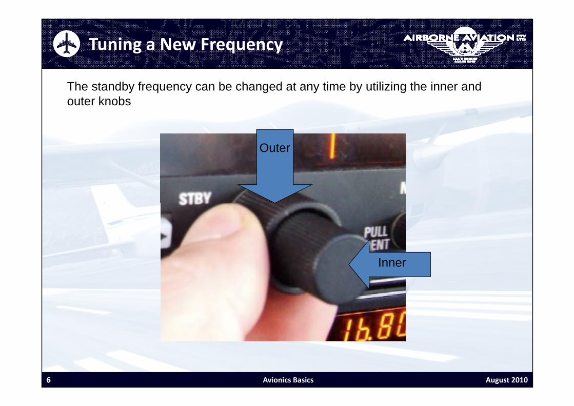
Tuning a New Frequency
The standby frequency can be changed at any time by utilizing the inner and outer knobs
Outer
Inner
6 August 20106 Avionics Basics

Tuning a New Frequency
The outer knob changes the number before theThe outer knob changes the number before the decimal place
7 August 20107 Avionics Basics

Tuning a New Frequency
The inner knob changes the numbers after theThe inner knob changes the numbers after the decimal place
8 August 20108 Avionics Basics

Tuning a New Frequency
When transmitting the radio will indicate TX
TXTX
9 August 20109 Avionics Basics

Tuning a New Frequency
When you are receiving a transmission RX will illuminateWhen you are receiving a transmission RX will illuminate
RX
10 August 201010 Avionics Basics

Changing Volume
T i th l th il t t th l k b l k i t dTo increase the volume the pilot turns the volume knob clockwise, to decrease volume turn the knob anti clockwise. To test the selected volume gently pull the knob outwards and you will get a static noise at the selected volume.
11 August 201011 Avionics Basics

Audio Selector
The audio panel controls what the pilot transmits and listens to
12 August 201012 Avionics Basics

Audio Selector
The transmit function is controlled by the dial below, currently Comm 1 is selected
13 August 201013 Avionics Basics
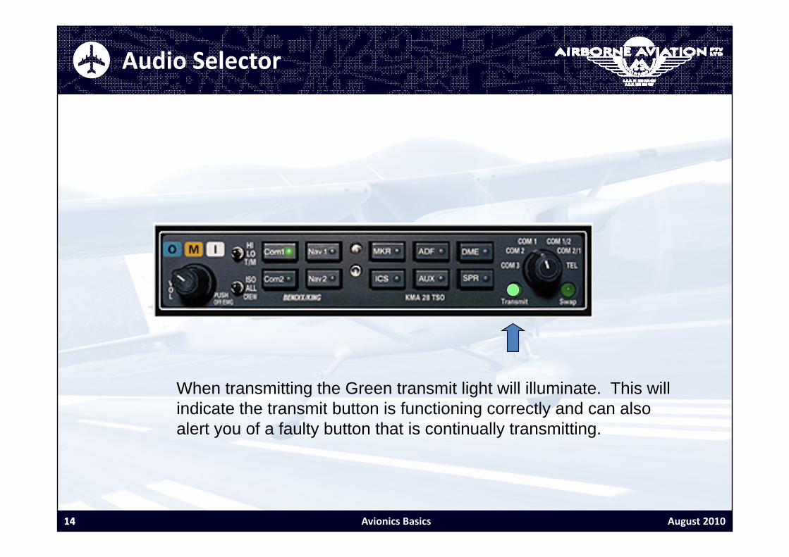
Audio Selector
When transmitting the Green transmit light will illuminate. This will i di t th t it b tt i f ti i tl d lindicate the transmit button is functioning correctly and can also alert you of a faulty button that is continually transmitting.
14 August 201014 Avionics Basics
Audio Selector
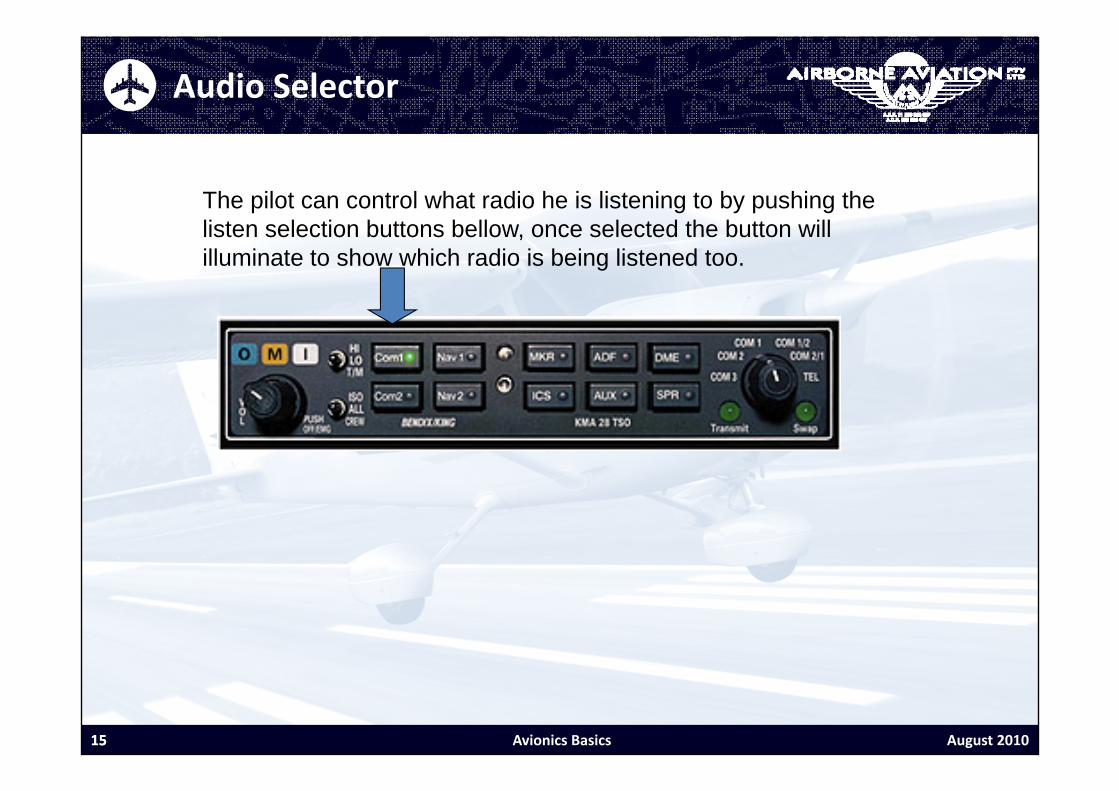
The pilot can control what radio he is listening to by pushing the listen selection buttons bellow, once selected the button will illuminate to show which radio is being listened too.
15 August 201015 Avionics Basics

Audio Selector
The Listen function will default to the radio that is selected on the transmit dial and cannot be turned off
16 August 201016 Avionics Basics

Audio Selector
When comm 1 is selected the pilot has the ability to also listen to comm 2 by pushing the button above. This can be very useful allowing the pilot to check the ATIS for example and still be able to monitor tower or ground
17 August 201017 Avionics Basics

Audio Selector
The pilot can also use the audio selector to identify navigation aids by pushing the relevant listen function. The graphic below shows us listening to comm 1 as well as also listening to the ADF.
18 August 201018 Avionics Basics
ADF
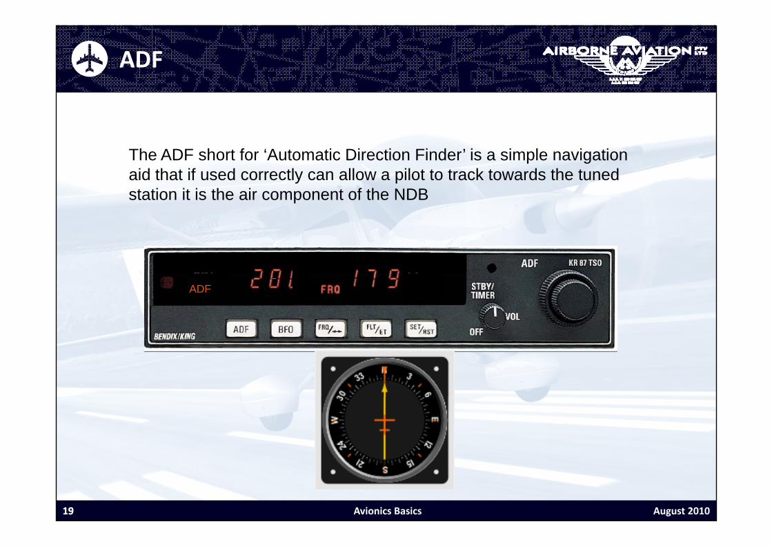
Th ADF h t f ‘A t ti Di ti Fi d ’ i i l i tiThe ADF short for ‘Automatic Direction Finder’ is a simple navigation aid that if used correctly can allow a pilot to track towards the tuned station it is the air component of the NDB
ADF
19 August 201019 Avionics Basics

Tuning The ADF
The ADF will default to a FLT mode which times the flight time.
ADFFLT:
20 August 201020 Avionics Basics

Tuning The ADF
ADF
To change to dual frequency mode push the FRQ button
21 August 201021 Avionics Basics

Tuning The ADF
ADF
To view your flight time at any point push the FLT button
22 August 201022 Avionics Basics

Tuning The ADF
In FRQ mode the ADF has a active frequency
ADF
23 August 201023 Avionics Basics

Tuning The ADF
Like the Radio the ADF has a active frequency
ADF
24 August 201024 Avionics Basics

Tuning The ADF
And a standby frequency
ADF
25 August 201025 Avionics Basics

Tuning The ADF
ADF
Y h b t th ti dYou can change between the active and standby buttons by using the toggle button
26 August 201026 Avionics Basics

Tuning The ADF
To change the Frequency much like the radio the operator uses the inner and out knobs. The outer knob changes the first number, the inner knob changes the 2nd, to change the third the inner knob must be gently pulled out before being rotated.
ADF
27 August 201027 Avionics Basics

Tune, Identify and Test
Once the desired frequency has been tuned and toggled over to theOnce the desired frequency has been tuned and toggled over to the active frequency it must be then identified and tested.
ADF
28 August 201028 Avionics Basics

Tune, Identify and Test
Identifying means confirming that we have tuned the correct aid. OnIdentifying means confirming that we have tuned the correct aid. On the chart where you found the Radio frequency it will also have Morse code which is a series of short or long beeps represented on the chart as small or long lines.g
ADF
29 August 201029 Avionics Basics
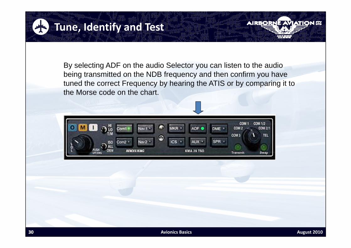
Tune, Identify and Test
By selecting ADF on the audio Selector you can listen to the audioBy selecting ADF on the audio Selector you can listen to the audio being transmitted on the NDB frequency and then confirm you have tuned the correct Frequency by hearing the ATIS or by comparing it to the Morse code on the chart.
ADF
30 August 201030 Avionics Basics

Tune, Identify and Test
In order to test the ADF, the indicated button must be depressed to getIn order to test the ADF, the indicated button must be depressed to get an ANT indication on the display. The needle in the 172’s will then point towards the right wing. Once you have confirmed the needle moved the unit can be switched back to ADF mode.
31 August 201031 Avionics Basics

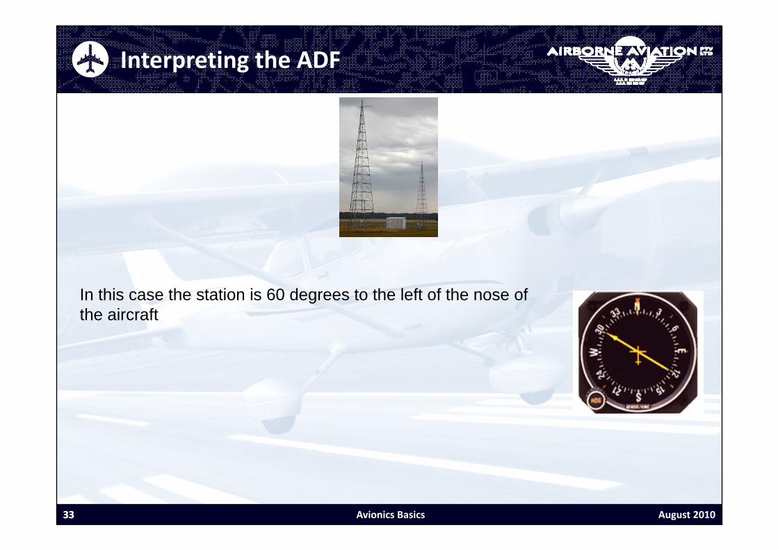
Interpreting the ADF
The ground based component of the ADF is the NDB or non-directional beaconThe ground based component of the ADF is the NDB or non directional beacon. If the ADF is tuned correctly the Needle will point towards the aerial, when taxiing the pilot should check the needle is operating in the normal sense. In the case below the aircrafts nose is pointing towards the station.below the aircrafts nose is pointing towards the station.
32 August 201032 Avionics Basics
Interpreting the ADF
In this case the station is 60 degrees to the left of the nose of the aircraft
33 August 201033 Avionics Basics

Interpreting the ADF
In this case the station is 15 degrees to the right of the tail of the aircraft
34 August 201034 Avionics Basics

Simple ADF Homing
The simplest way to use an ADF is simple homing. If you maintain a heading that keeps the needle pointing towards the nose the aircraft may not fly a perfectlykeeps the needle pointing towards the nose the aircraft may not fly a perfectly straight path however due to wind but it will eventually pass over the station
35 August 201035 Avionics Basics

Transponder
A transponder is a device that returns a signal to a ground based radar system making the aircraft visible to the controller. As well as a basic return the transponder is capable of broadcasting altitude and a code.
36 August 201036 Avionics Basics

Transponder Modes
The transponder can operate in several modes selected by the knob b lbelow.
37 August 201037 Avionics Basics

Transponder Modes
The transponder is not functional when the knob is selected to off
38 August 201038 Avionics Basics

Transponder Modes
Standby (SBY) powers the unit up and allows the operator to change th d ith t t itti t Th it h ld l b t ithe code without transmitting a return. The unit should always be put in this mode whenever the code is being changed to avoid accidentally transmitting an unintentional code.
39 August 201039 Avionics Basics

Transponder Modes
TST or test mode lights up all possible parts of the display to allow the t if t f th di l i i bluser to see if part of the display is unserviceable
40 August 201040 Avionics Basics

Transponder Modes
The On mode transmits the aircrafts position and selected code but not th ltit dthe altitude
41 August 201041 Avionics Basics

Transponder Modes
The Altitude (ALT) mode transmits the aircrafts position, code and ltit d Th t d h ld b t t ltit d d b f thaltitude. The transponder should be set to altitude mode before the
aircraft enters the runway unless instructed otherwise by ATC.
42 August 201042 Avionics Basics

Transponder Code Operation
To make individual aircraft easier to identify when entering controlled airspace the controller will instruct you to ‘Squawk’ a code. When changing code the transponder must be put in ‘SBY’ mode. The operator then pushes the numbered keys on the lower portion of the unit to change the ‘Squawk’ code. Once the code is selected the t d h ld b t b k i t ALT dtransponder should be put back into ALT mode
43 August 201043 Avionics Basics

Transponder Code Operation
When VFR aircraft are operating outside controlled airspace they are expected to Squawk 1200. If changing from another code to 1200, pushing the VFR button will automatically select code 1200. Because there is no possibility of selecting another code while the numbers are being changed the transponder can be left on ALT mode.
44 August 201044 Avionics Basics
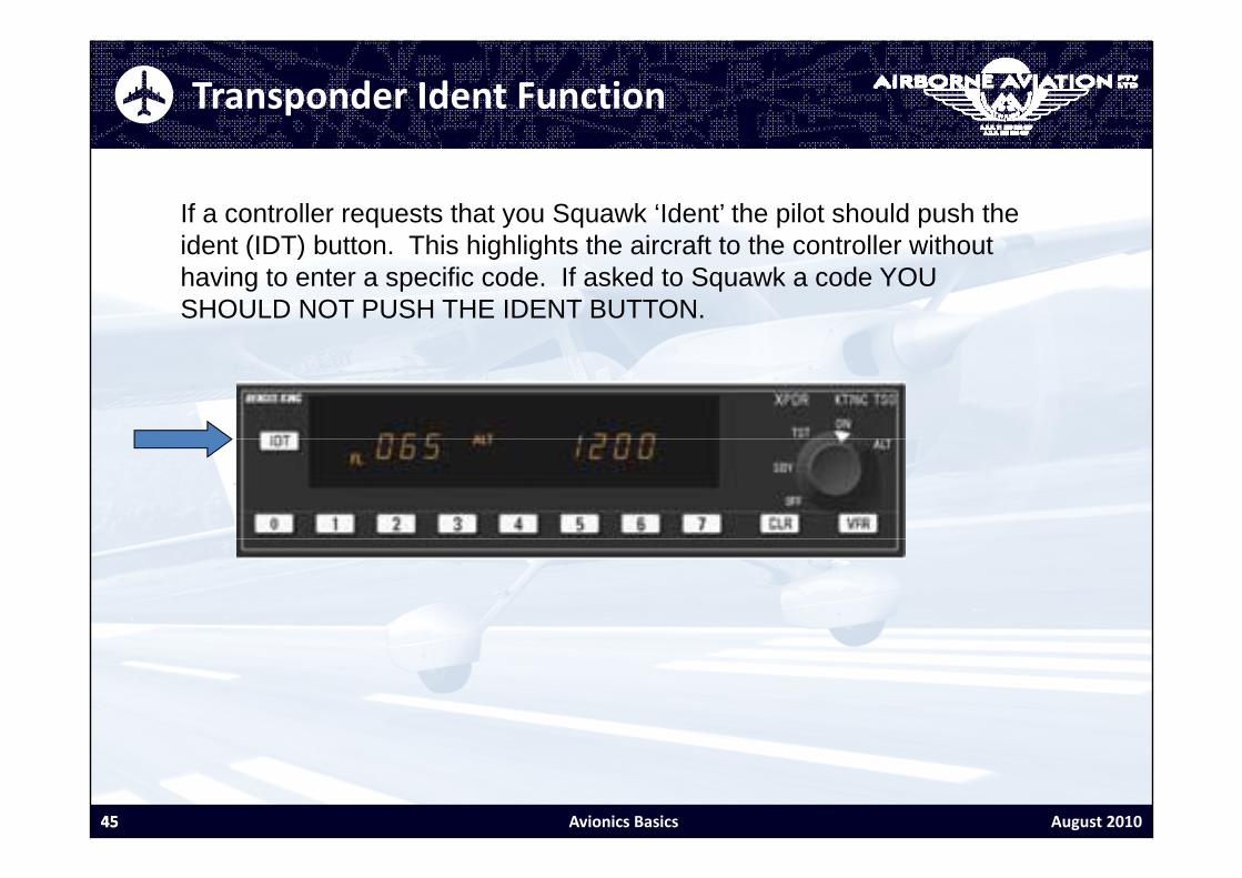
Transponder Ident Function
If a controller requests that you Squawk ‘Ident’ the pilot should push the id t (IDT) b tt Thi hi hli ht th i ft t th t ll ith tident (IDT) button. This highlights the aircraft to the controller without having to enter a specific code. If asked to Squawk a code YOU SHOULD NOT PUSH THE IDENT BUTTON.
45 August 201045 Avionics Basics

Transponder Functions
If an error is made while entering a code the Clear button can be used t t th dto reset the code.
46 August 201046 Avionics Basics

Avionics Basics
This on-line guide is for personal reference only and is not in any way d i d i t d d t b b tit t f i di id l f tdesigned or intended to be a substitute for individual manufacturers operating handbooks.
All efforts have been made to present information in an up to date and concise manner.
Any questions regarding the operation of your aircrafts radio’s and navigational aids should be referred to your instructornavigational aids should be referred to your instructor.
47 August 201047 Avionics Basics