av
118
AV-1 AUDIO, VISUAL & TELEPHONE SYSTEM K ELECTRICAL CONTENTS C D E F G H I J L M SECTION A B AV AUDIO, VISUAL & TELEPHONE SYSTEM PRECAUTIONS ......................................................... 3 Precautions for Supplemental Restraint System (SRS) “AIR BAG” and “SEAT BELT PRE-TEN- SIONER” ................................................................. 3 Wiring Diagrams and Trouble Diagnosis ................. 3 AUDIO ........................................................................ 4 System Description ................................................. 4 AUDIO SYSTEM .................................................. 4 AV COMMUNICATION LINE ................................ 4 NATS AUDIO LINK .............................................. 4 SPEED DEPENDENT VOLUME CONTROL ....... 5 PERSONAL AUDIO SETTINGS .......................... 5 Component Parts Location ...................................... 5 Schematic ............................................................... 6 VFD MONITOR .................................................... 6 LCD MONITOR .................................................... 7 WITH NAVIGATION SYSTEM .............................. 8 Wiring Diagram—AUDIO— ..................................... 9 VFD MONITOR FOR LHD MODELS ................... 9 VFD MONITOR FOR RHD MODELS ................ 13 LCD MONITOR FOR LHD MODELS ................. 17 LCD MONITOR FOR RHD MODELS ................ 21 WITH NAVIGATION SYSTEM FOR LHD MOD- ELS .................................................................... 25 WITH NAVIGATION SYSTEM FOR RHD MOD- ELS .................................................................... 30 Terminals and Reference Value for Audio Unit ...... 35 Terminals and Reference Value for Sub-woofer .... 37 Terminals and Reference Value for CD Auto Changer ................................................................ 38 Self-Diagnosis Function ........................................ 38 DESCRIPTION ................................................... 38 DIAGNOSIS ITEM .............................................. 39 Self-Diagnosis Mode ............................................. 39 OPERATION PROCEDURE .............................. 39 Trouble Diagnosis ................................................. 39 PROBLEM WITH RADIO, TAPE, AND CD ........ 39 FOR RADIO ONLY ............................................. 39 FOR CASSETTE PLAYER ONLY ...................... 40 FOR CD ONLY ................................................... 40 Noise Inspection .................................................... 40 TYPE OF NOISE AND POSSIBLE CAUSE ....... 40 Power Supply Circuit Inspection ............................ 41 Audio System Does Not Turn On. ......................... 42 Removal and Installation of Audio Unit .................. 42 Removal and Installation of Door Speaker ............ 43 Removal and Installation of Front Pillar Tweeter ... 43 AUDIO ANTENNA ................................................... 44 Location of Antenna ............................................... 44 Removal and Installation of Roof Antenna ............ 45 TELEPHONE (PRE WIRE) ...................................... 46 Wiring Diagram — PHONE — ............................... 46 NAVIGATION SYSTEM ............................................ 47 System Description ................................................ 47 TRAVEL DISTANCE ........................................... 47 TRAVEL DIRECTION ......................................... 47 MAP-MATCHING ................................................ 47 GPS (GLOBAL POSITIONING SYSTEM) .......... 48 COMPONENT DESCRIPTION ........................... 49 BIRDVIEW® ....................................................... 49 MAP DISPLAY .................................................... 50 FUNCTION OF MULTIFUNCTION SWITCH ...... 51 “VIEW” MODE .................................................... 54 “HEADING” MODE ............................................. 54 “NEARBY DISPLAY ICONS” MODE .................. 55 “SAVE CURRENT LOCATION” MODE .............. 55 “EDIT ADDRESS BOOK” MODE ....................... 55 “CLEAR MEMORY” MODE ................................ 55 “AUTO RE-ROUTE” MODE ................................ 56 “QUICK STOP CUSTOMER SETTINGS” MODE ... 56 “SET AVERAGE SPEED FOR ESTIMATED JOURNEY TIME” MODE .................................... 56 “GPS INFORMATION” MODE ............................ 56 “TRACKING” MODE ........................................... 57 “ADJUST CURRENT LOCATION” MODE .......... 57 GUIDE VOLUME SETTING ............................... 57 NATS NAVI LINK ................................................ 58 Precautions for AV and NAVI Control Unit Replace- ment ....................................................................... 58 Component Parts Location .................................... 59
-
Upload
mihai-iavorschi -
Category
Documents
-
view
2 -
download
0
Transcript of av

AV-1
AUDIO, VISUAL & TELEPHONE SYSTEM
K ELECTRICAL
CONTENTS
C
D
E
F
G
H
I
J
L
M
SECTION
A
B
AV
AUDIO, VISUAL & TELEPHONE SYSTEM
PRECAUTIONS .......................................................... 3Precautions for Supplemental Restraint System(SRS) “AIR BAG” and “SEAT BELT PRE-TEN-SIONER” .................................................................. 3Wiring Diagrams and Trouble Diagnosis .................. 3
AUDIO ......................................................................... 4System Description .................................................. 4
AUDIO SYSTEM ................................................... 4AV COMMUNICATION LINE ................................. 4NATS AUDIO LINK ............................................... 4SPEED DEPENDENT VOLUME CONTROL ........ 5PERSONAL AUDIO SETTINGS ........................... 5
Component Parts Location ....................................... 5Schematic ................................................................ 6
VFD MONITOR ..................................................... 6LCD MONITOR ..................................................... 7WITH NAVIGATION SYSTEM ............................... 8
Wiring Diagram—AUDIO— ...................................... 9VFD MONITOR FOR LHD MODELS .................... 9VFD MONITOR FOR RHD MODELS ................. 13LCD MONITOR FOR LHD MODELS .................. 17LCD MONITOR FOR RHD MODELS ................. 21WITH NAVIGATION SYSTEM FOR LHD MOD-ELS ..................................................................... 25WITH NAVIGATION SYSTEM FOR RHD MOD-ELS ..................................................................... 30
Terminals and Reference Value for Audio Unit ....... 35Terminals and Reference Value for Sub-woofer ..... 37Terminals and Reference Value for CD AutoChanger ................................................................. 38Self-Diagnosis Function ......................................... 38
DESCRIPTION .................................................... 38DIAGNOSIS ITEM ............................................... 39
Self-Diagnosis Mode .............................................. 39OPERATION PROCEDURE ............................... 39
Trouble Diagnosis .................................................. 39PROBLEM WITH RADIO, TAPE, AND CD ......... 39FOR RADIO ONLY .............................................. 39FOR CASSETTE PLAYER ONLY ....................... 40FOR CD ONLY .................................................... 40
Noise Inspection ..................................................... 40TYPE OF NOISE AND POSSIBLE CAUSE ........ 40
Power Supply Circuit Inspection ............................. 41Audio System Does Not Turn On. .......................... 42Removal and Installation of Audio Unit ................... 42Removal and Installation of Door Speaker ............. 43Removal and Installation of Front Pillar Tweeter .... 43
AUDIO ANTENNA .................................................... 44Location of Antenna ................................................ 44Removal and Installation of Roof Antenna ............. 45
TELEPHONE (PRE WIRE) ....................................... 46Wiring Diagram — PHONE — ................................ 46
NAVIGATION SYSTEM ............................................. 47System Description ................................................. 47
TRAVEL DISTANCE ............................................ 47TRAVEL DIRECTION .......................................... 47MAP-MATCHING ................................................. 47GPS (GLOBAL POSITIONING SYSTEM) ........... 48COMPONENT DESCRIPTION ............................ 49BIRDVIEW® ........................................................ 49MAP DISPLAY ..................................................... 50FUNCTION OF MULTIFUNCTION SWITCH ....... 51“VIEW” MODE ..................................................... 54“HEADING” MODE .............................................. 54“NEARBY DISPLAY ICONS” MODE ................... 55“SAVE CURRENT LOCATION” MODE ............... 55“EDIT ADDRESS BOOK” MODE ........................ 55“CLEAR MEMORY” MODE ................................. 55“AUTO RE-ROUTE” MODE ................................. 56“QUICK STOP CUSTOMER SETTINGS” MODE... 56“SET AVERAGE SPEED FOR ESTIMATEDJOURNEY TIME” MODE ..................................... 56“GPS INFORMATION” MODE ............................. 56“TRACKING” MODE ............................................ 57“ADJUST CURRENT LOCATION” MODE ........... 57GUIDE VOLUME SETTING ................................ 57NATS NAVI LINK ................................................. 58
Precautions for AV and NAVI Control Unit Replace-ment ........................................................................ 58Component Parts Location ..................................... 59

AV-2
Location of Antenna ................................................ 60Schematic ............................................................... 61Wiring Diagram —NAVI— ....................................... 62Schematic For AV Communication Line ................. 68Wiring Diagram — COMM — ................................. 69Terminals and Reference Value for AV and NAVIControl Unit ............................................................. 72Terminals and Reference Value for Display Unit .... 75Terminals and Reference Value for MultifunctionSwitch ..................................................................... 77Self-Diagnosis Function .......................................... 78
DESCRIPTION .................................................... 78SELF-DIAGNOSIS ITEM ..................................... 78
Self-Diagnosis Mode .............................................. 78OPERATION PROCEDURE ............................... 78DIAGNOSIS CHART ........................................... 80DIAGNOSIS NUMBER CHART ........................... 80
CONFIRMATION/ADJUSTMENT Mode ................. 81OPERATION PROCEDURE ................................ 81DISPLAY .............................................................. 82VEHICLE SIGNALS ............................................. 82NAVIGATION ....................................................... 83HISTORY OF ERRORS ...................................... 84DIAGNOSIS BY HISTORY OF ERRORS ............ 84AUTO CLIMATE CONTROL ................................ 86SERVICE ............................................................. 86
Power Supply and Ground Circuit Check ............... 87Check Display Unit, Multifunction Switch Power,and Ground Circuit ................................................. 88Vehicle Speed Signal Check .................................. 89Illumination Control Signal Check ........................... 90Ignition Signal Check .............................................. 90Reverse Signal Check ............................................ 91RGB Screen Is Not Shown. .................................... 91No Screens Appear ................................................ 92Color of RGB Image Is Not Proper. ........................ 93RGB Screen Is Rolling ............................................ 96Guide Sound Is Not Heard. .................................... 96Multifunction Switch Controls Are Ineffective (RearDefogger Control Excluded). .................................. 97Air Conditioning Controls (Only) Are Ineffective(Rear Defogger Control Excluded). ...................... 100Rear Defogger Does Not Operate ........................ 101Rear Defogger IndicatorLamp DoesNot Illuminate.. 102No Fuel Information Is Displayed/No Warning Mes-sage Is Displayed ................................................. 102Previous Conditions Are Not Stored. .................... 104The Position of The Current-Location Mark Is NotCorrect. ................................................................. 104Radio Wave From The GPS Satellite Is Not
Received. ..............................................................104Display Does Not Change When Screen Adjust-ment Is Performed. ...............................................105Day/Night Display Switching Is Not Done. Night Illu-mination for AV and NAVI Control Unit Does Not Illu-minate. ..................................................................105On Multifunction switch, a Specific Switch Does NotOperate in All Conditions. .....................................105Driving Information Is Inaccurate. MaintenanceInformation Is Inaccurate. .....................................105System Does Not Start. .........................................105The Current Position Mark Is in the Wrong Place..106The Current-Location Mark Will Not Move Forward/Backward. .............................................................107The Position of the Current-Location Mark Is NotCorrect. .................................................................107Driving Test ...........................................................107Example of Symptoms Judged Not Abnormal ......108
BASIC OPERATION ..........................................108VEHICLE MARK ................................................109DESTINATION, PASSING POINTS, AND MENUITEMS CANNOT BE SELECTED/SET. .............109VOICE GUIDE ................................................... 110ROUTE SEARCHING ........................................ 110EXAMPLES OF CURRENT-LOCATION MARKDISPLACEMENT ............................................... 111THE CURRENT POSITION MARK SHOWS APOSITION WHICH IS COMPLETELY WRONG.. 114THE CURRENT POSITION MARK JUMPS. ..... 114THE CURRENT LOCATION MARK IS IN ARIVER OR THE SEA. ........................................ 115WHEN DRIVING ON THE SAME ROAD, SOME-TIMES THE CURRENT-LOCATION MARK IS INTHERIGHTPLACEANDSOMETIMESITISTHEWRONG PLACE. ............................................... 115LOCATION CORRECTION BYMAPMATCHINGIS SLOW. ........................................................... 115ALTHOUGH THE GPS RECEIVING DISPLAY ISGREEN, THE VEHICLE MARK DOES NOTRETURN TO THE CORRECT LOCATION. ....... 115THE NAME OF THE CURRENT PLACE IS NOTDISPLAYED. ...................................................... 115CONTENTS OF THE DISPLAY DIFFER FORTHE BIRDVIEW® AND THE (FLAT) MAPSCREEN. ........................................................... 115
Program Loading .................................................. 116Removal and Installation of AV&NAVI Control Unit. 116Removal and Installation of GPS Antenna ............ 117Removal and Installation of Multifunction Switch .. 117Removal and Installation of Display Unit Assembly. 117

PRECAUTIONS
AV-3
C
D
E
F
G
H
I
J
L
M
A
B
AV
PRECAUTIONS PFP:00011
Precautions for Supplemental Restraint System (SRS) “AIR BAG” and “SEATBELT PRE-TENSIONER” EKS0048T
The Supplemental Restraint System such as "AIR BAG" and "SEAT BELT PRE-TENSIONER", used alongwith a front seat belt, helps to reduce the risk or severity of injury to the driver and front passenger for certaintypes of collision. Information necessary to service the system safely is included in the SRS and SB section ofthis Service Manual.WARNING:● To avoid rendering the SRS inoperative, which could increase the risk of personal injury or death
in the event of a collision which would result in air bag inflation, all maintenance must be per-formed by an authorized NISSAN/INFINITI dealer.
● Improper maintenance, including incorrect removal and installation of the SRS, can lead to per-sonal injury caused by unintentional activation of the system. For removal of Spiral Cable and AirBag Module, see the SRS section.
● Do not use electrical test equipment on any circuit related to the SRS unless instructed to in thisService Manual. SRS wiring harnesses can be identified by yellow and/or orange harness connec-tors.
Wiring Diagrams and Trouble Diagnosis EKS0040U
When you read wiring diagrams, refer to the following:● GI-14, "How to Read Wiring Diagrams" in GI section● PG-3, "POWER SUPPLY ROUTING" for power distribution circuit in GI sectionWhen you perform trouble diagnosis, refer to the following:● GI-11, "HOW TO FOLLOW TEST GROUPS IN TROUBLE DIAGNOSES" in GI section● GI-24, "How to Perform Efficient Diagnosis for an Electrical Incident" in GI section

AV-4
AUDIO
AUDIO PFP:28111
System Description EKS0040V
AUDIO SYSTEMRefer to Owner’s Manual for audio system operating instructions.Power is supplied at all times● through 15A fuse [No. 33, located in the fuse, fusible link and relay block (J/B)]● to audio unit terminals 3,4.● to CD auto changer terminal 32With the ignition switch in the ACC or ON position, power is supplied● through 10A fuse [No. 1, located in the fuse block (J/B)]● to audio unit terminal 2.● to CD auto changer terminal 36.● to Sub-woofer terminal 4.Ground is supplied through the case of the audio unit.Ground is also supplied to CD auto changer terminal 35 through body grounds B17, B24 and D94.Ground is also supplied to Sub-woofer terminal 3 through body ground B17, B24 and D94.
Audio signals are supplied● through audio unit terminals 5, 6, 7, 8, 9, 10, 11, 12● to terminals 1 and 2 of front door speaker LH and RH● to terminals 1 and 2 of rear door speaker LH and RH● to terminals 1 and 2 of tweeter LH and RH● to terminals 1, 2, 5 and 6 of Sub-woofer (with 7 speakers)
AV COMMUNICATION LINEAudio system components (Audio unit, Display, etc.) are connected by AV communication line and controlledby signals from the multifunction switch.
NATS AUDIO LINKDescriptionThe link with the NATS IMMU implies that the audio unit can basically only be operated if connected to thematching NATS IMMU to which the audio unit was initially fitted on the production line.Since radio operation is impossible after the link with the NATS is disrupted theft of the audio unit is basicallyuseless since special equipment is required to reset the audio unit.Initialization process for audio units that are linked to the NATS IMMU● Perform initialization with CONSULT-II● For initialization, refer to “CONSULT-II operation manual NATS”.Normal operationEach time the audio unit is switched on afterwards, the audio unit code will be verified between the audio unitand the NATS before the audio unit becomes operational. During the code verification process, “WAIT” isshown on the Display unit. Again, the communication takes such a short time that the audio unit seems toswitch on directly without showing “WAIT” on the Display unit.When the radio is lockedWhen NATS link problems occur “SECURE” message will be displayed in three ways indicating three differentNATS link problems.“Secure” on a red background indicates that there is a problem in the link between Navi control unit and Audio,suggesting that there is either a Navigation system fault or the Navi control unit has previously been fitted inanother vehicle.“Secure” on a green background indicates that there is a problem in the link between NATS IMMU and Audio,suggesting that there is an audio fault or the audio unit has previously been fitted in another vehicle.“Secure” on a yellow background indicates that the transponder (NATS key) is not working correctly or it haspreviously been fitted in another vehicle.When a “Secure” message (of any type) is displayed, it can be cleared by re-initializing the NATS systemusing CONSULT-II and the associated Immobilizer PIN code (there is no need to return the audio to a Clarion

AUDIO
AV-5
C
D
E
F
G
H
I
J
L
M
A
B
AV
service centre). If re-initializing fails to clear a “Secure” message then the component (identified by back-ground color) is faulty and should be replaced.NOTE:When the “Secure” is displayed on VFD display, the communication of IMMU and radio, radio unit or transpon-der has problem.
Service Procedure
SPEED DEPENDENT VOLUME CONTROLDescriptionIf activated, the radio output volume will be automatically adjusted to compensate for increased driving noisesat higher driving speeds.The radio receives a speed signal from the combination meter and selects the output volume.
PERSONAL AUDIO SETTINGSDescriptionThe radio is designed to store several settings (volume, bass, treble, preset stations and level of speed depen-dent volume control) with every NATS ignition key used. Up to a maximum of 4 NATS keys can be registered.During the communication mentioned under “Anti-Theft System”, the radio will recognize the used ignition keyand select the accompanying settings.
Component Parts Location EKS0041L
AV-59, "Component Parts Location" in “NAVIGATION SYSTEM”.
Item Service procedure Description
Battery disconnection No additional action required. —
Radio needs repair Repair needs to be done by authorizedrepresentative of radio manufacturer sinceradio cannot be operated unless it is resetto NEW state, using special decodingequipment.
—
Replacement of radio by new part No additional action required. Radio is delivered in NEW state.
Transferring radio to another vehicle/replacement of radio by an “old” part
Radio needs to be reset by using CON-SULT-II and the associated Immobi PINcode (there is no need to return the audioor Navi units to a Clarion service centre).
—
Replacement of IMMU The communication between IMMU andradio need to be reset by using CONSULT-II and the associated Immobi PIN code.
After switching on the radio, it will display“SECURE” on a green background.
No communication from IMMU to radio 1. If NATS is malfunctioning, check NATSsystem.
2. After NATS is repaired, reset radio to“Secure” on a green background stateby using CONSULT-II and the associ-ated Immobilizer PIN code (there is noneed to return the audio to a Clarion ser-vice centre).
After switching on the radio, the displayunit will display “SECURE” on a greenbackground. Further use of radio is impos-sible until communication is establishedagain, or after radio is reset by using CON-SULT-II and the associated ImmobilizerPIN code (there is no need to return theaudio to a Clarion service centre).

AV-6
AUDIO
Schematic EKS0040W
VFD MONITOR
MKWA0058E

AUDIO
AV-7
C
D
E
F
G
H
I
J
L
M
A
B
AV
LCD MONITOR
MKWA0067E

AV-8
AUDIO
WITH NAVIGATION SYSTEM
MKWA0076E
AUDIO
AV-9
C
D
E
F
G
H
I
J
L
M
A
B
AV
Wiring Diagram—AUDIO— EKS0040X
VFD MONITOR FOR LHD MODELS
MKWA0059E

AV-10
AUDIO
MKWA0060E

AUDIO
AV-11
C
D
E
F
G
H
I
J
L
M
A
B
AV
MKWA0061E

AV-12
AUDIO
MKWA0062E

AUDIO
AV-13
C
D
E
F
G
H
I
J
L
M
A
B
AV
VFD MONITOR FOR RHD MODELS
MKWA0063E
AV-14
AUDIO
MKWA0064E

AUDIO
AV-15
C
D
E
F
G
H
I
J
L
M
A
B
AV
MKWA0065E

AV-16
AUDIO
MKWA0066E

AUDIO
AV-17
C
D
E
F
G
H
I
J
L
M
A
B
AV
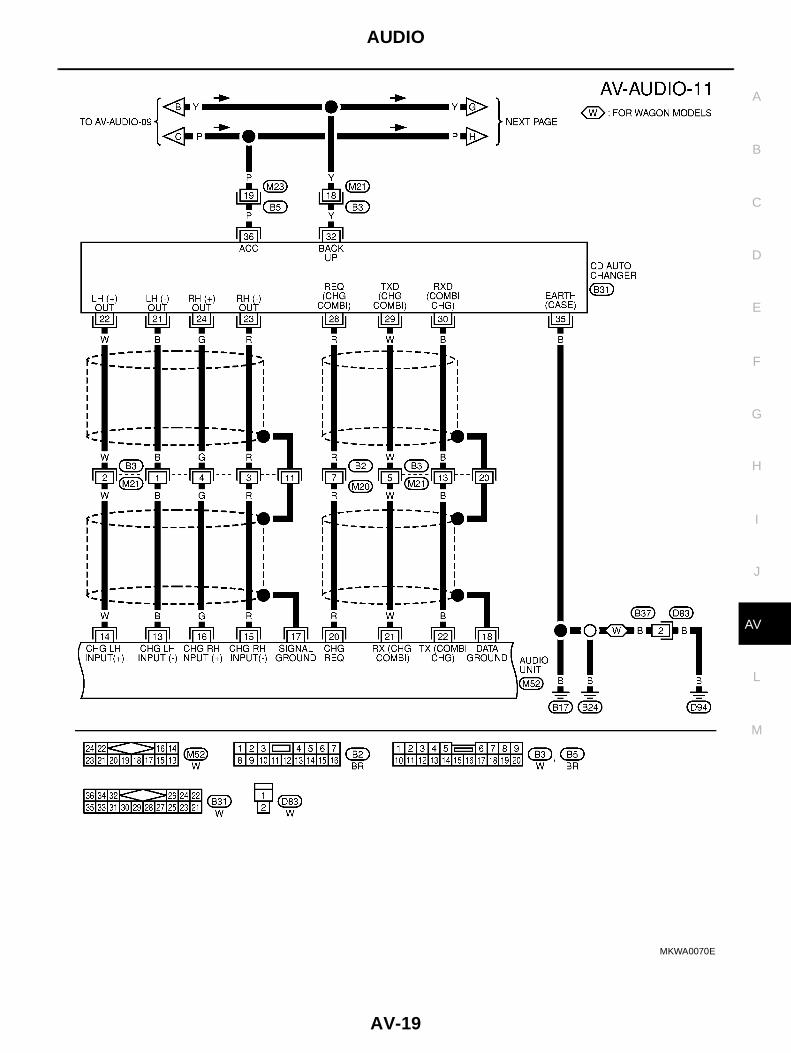
LCD MONITOR FOR LHD MODELS
MKWA0068E

AV-18
AUDIO
MKWA0069E
AUDIO
AV-19
C
D
E
F
G
H
I
J
L
M
A
B
AV
MKWA0070E

AV-20
AUDIO
MKWA0071E
AUDIO
AV-21
C
D
E
F
G
H
I
J
L
M
A
B
AV
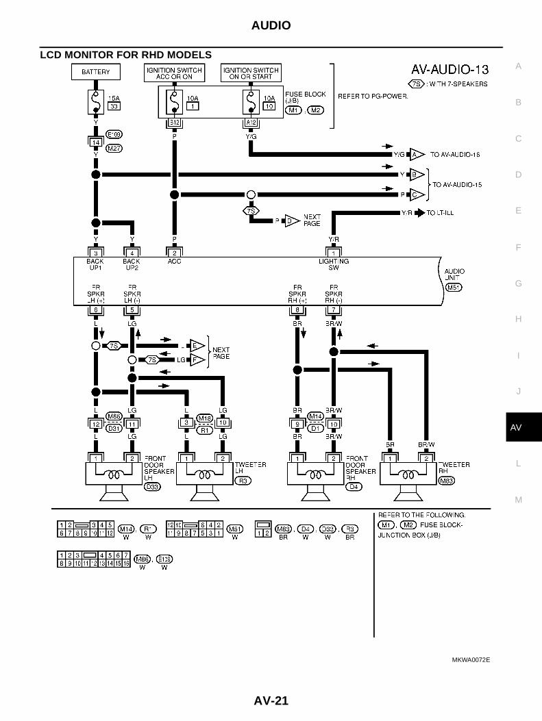
LCD MONITOR FOR RHD MODELS
MKWA0072E

AV-22
AUDIO
MKWA0073E

AUDIO
AV-23
C
D
E
F
G
H
I
J
L
M
A
B
AV
MKWA0074E
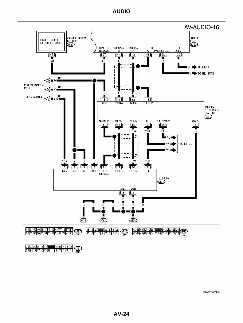
AV-24
AUDIO
MKWA0075E

AUDIO
AV-25
C
D
E
F
G
H
I
J
L
M
A
B
AV
WITH NAVIGATION SYSTEM FOR LHD MODELS
MKWA0077E

AV-26
AUDIO
MKWA0078E

AUDIO
AV-27
C
D
E
F
G
H
I
J
L
M
A
B
AV
MKWA0079E

AV-28
AUDIO
MKWA0080E

AUDIO
AV-29
C
D
E
F
G
H
I
J
L
M
A
B
AV
MKWA0081E
AV-30
AUDIO
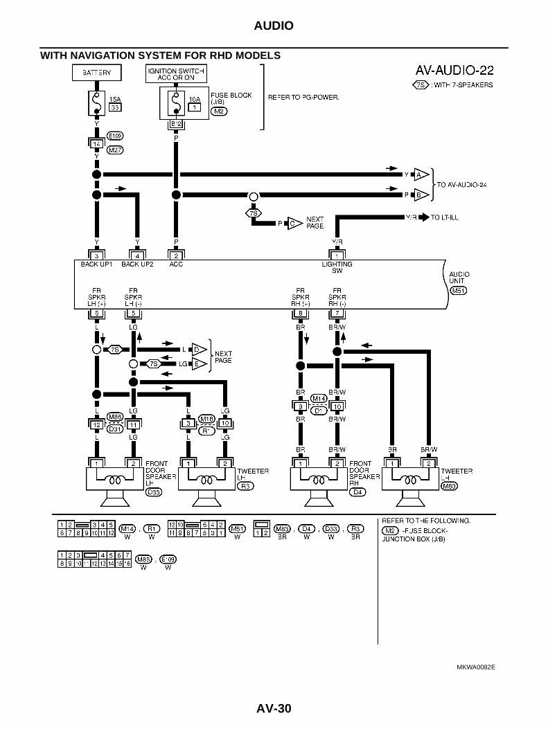
WITH NAVIGATION SYSTEM FOR RHD MODELS
MKWA0082E

AUDIO
AV-31
C
D
E
F
G
H
I
J
L
M
A
B
AV
MKWA0083E
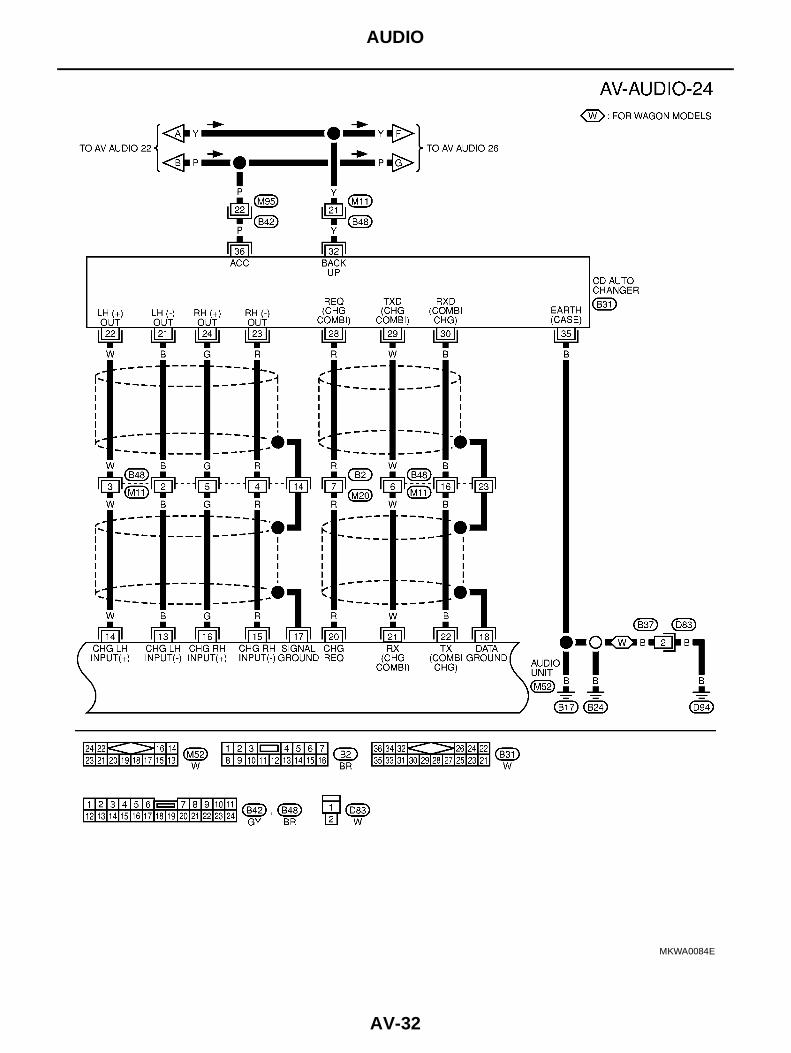
AV-32
AUDIO
MKWA0084E

AUDIO
AV-33
C
D
E
F
G
H
I
J
L
M
A
B
AV
MKWA0085E
AV-34
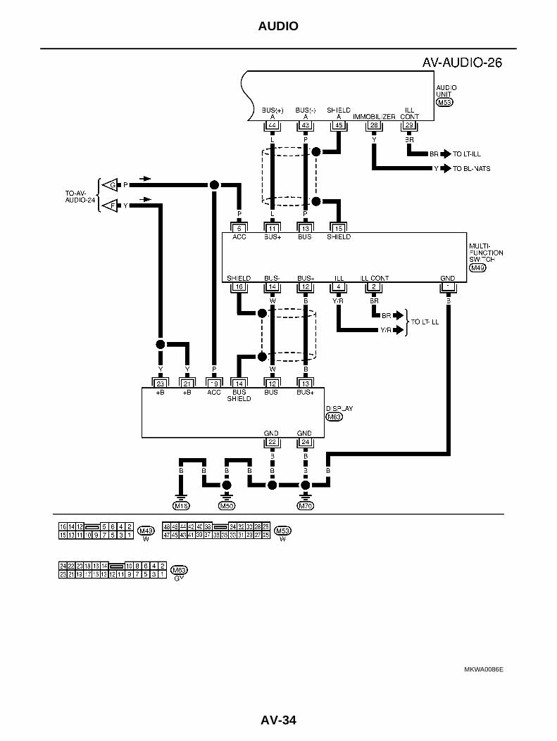
AUDIO
MKWA0086E

AUDIO
AV-35
C
D
E
F
G
H
I
J
L
M
A
B
AV
Terminals and Reference Value for Audio Unit EKS0041O
Terminal No.(wire color)
ItemSignalinput/output
Condition
Voltage Example of symptom
+ –Ignitionswitch
Operation
1(Y/R) groundIlluminationsignal
Input OFF
Lightingswitch is ON(position 1).
Battery voltage Audio unit illuminationdoes not come onwhen lighting switch isON (position 1).Turn lighting
switch OFF.Approx. 3.0V or less
2(P) ground ACC power Input ACC - Battery voltageAudio unit operation isnot possible.
3(Y) ground Battery power Input OFF - Battery voltageAudio unit operation isnot possible.
4(Y) ground Battery power Input OFF - Battery voltageAudio unit operation isnot possible.
6(L) 5(LG)Speaker out-put (front LH)
Output ONReceive radiobroadcast
No sound from front LHspeaker.
8(BR)7(BR/
W)Speaker out-put (front RH)
Output ONReceive radiobroadcast
No sound from frontRH speaker.
10(LG) 9(B/Y)Speaker out-put (rear LH)
Output ONReceive radiobroadcast
No sound from rear LHspeaker.
12(L) 11(P)Speaker out-put (rear RH)
Output ONReceive radiobroadcast
No sound from rear RHspeaker.
14 (W) 13 (B)CD sound sig-nal (LH)
Input ON Play CD.CD sound is not heardfrom LH speaker.
SKIA0177E
SKIA0177E
SKIA0177E
SKIA0177E
SKIA0195E

AV-36
AUDIO
16 (G) 15 (R)CD sound sig-nal (RH)
Input ON Play CD.CD sound is not heardfrom RH speaker.
20 (R) groundCommunica-tion signal(CHG REQ)
Input ONInsert/ejectmagazine.
CD Auto changer oper-ation is not possible.
21 (W) ground
Communica-tion signal(CHG toCOMB)
Input ONInsert/ejectmagazine.
CD Auto changer oper-ation is not possible.
22 (G) ground
Communica-tion signal(COMB toCHG)
Output ONPress the discswitch.
CD Auto changer oper-ation is not possible.
29(BR) groundIlluminationcontrol signal
Input ON
Illuminationcontrol switchis operated bylighting switchin 1st position.
Changes between approx. 0 andapprox. 12V.
Audio unit illuminationcannot be controlled.
38(BR) 37(Y)Voice guidesignal
Input ONPress the"voice" switch.
Only route guide andoperation guide are notheard.
39(B) - Shield ground - - - - -
43(P) groundCommunica-tion signal (-)
Input/output
ON -System does not workproperly.
Terminal No.(wire color)
ItemSignalinput/output
Condition
Voltage Example of symptom
+ –Ignitionswitch
Operation
SKIA0195E
SKIA0196E
SKIA0197E
SKIA0198E
SKIA0171E
SKIA0176E

AUDIO
AV-37
C
D
E
F
G
H
I
J
L
M
A
B
AV
Terminals and Reference Value for Sub-woofer EKS004M3
44(L) groundCommunica-tion signal (+)
Input/output
ON -System does not workproperly.
45 - Shield ground - - - - -
46(B) - Shield ground - - - - -
47(G) groundCommunica-tion signal (-)
Input/output
ON -System does not workproperly.
48(R) groundCommunica-tion signal (+)
Input/output
ON -System does not workproperly.
Terminal No.(wire color)
ItemSignalinput/output
Condition
Voltage Example of symptom
+ –Ignitionswitch
Operation
SKIA0175E
SKIA0176E
SKIA0175E
Terminal No.(wire color)
ItemSignalinput/output
Condition
Voltage Example of symptom
+ –Ignitionswitch
Operation
2(L) 1(LG)Audio soundsignal (LH)
Input ONReceive radiobroadcast
Audio sound notheard sub-woofer.
3(B) ground Ground - ON - - -
4(P) ground ACC power Input ACC - Battery voltageSub-woofer does notwork.
6(L) 5(P)Audio soundsignal (RH)
Input ONReceive radiobroadcast
Audio sound notheard sub-woofer.
SKIA0177E
SKIA0177E
AV-38
AUDIO
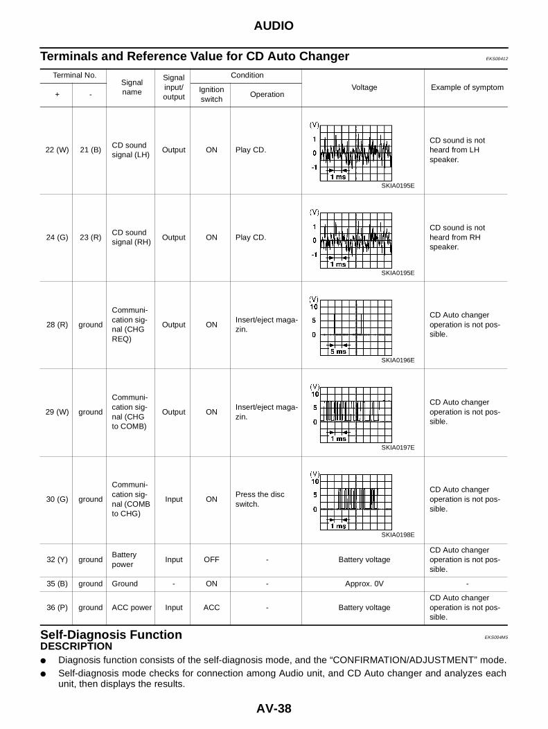
Terminals and Reference Value for CD Auto Changer EKS00412
Self-Diagnosis Function EKS004M5
DESCRIPTION● Diagnosis function consists of the self-diagnosis mode, and the “CONFIRMATION/ADJUSTMENT” mode.● Self-diagnosis mode checks for connection among Audio unit, and CD Auto changer and analyzes each
unit, then displays the results.
Terminal No.Signalname
Signalinput/output
Condition
Voltage Example of symptom+ -
Ignitionswitch
Operation
22 (W) 21 (B)CD soundsignal (LH)
Output ON Play CD.CD sound is notheard from LHspeaker.
24 (G) 23 (R)CD soundsignal (RH)
Output ON Play CD.CD sound is notheard from RHspeaker.
28 (R) ground
Communi-cation sig-nal (CHGREQ)
Output ONInsert/eject maga-zin.
CD Auto changeroperation is not pos-sible.
29 (W) ground
Communi-cation sig-nal (CHGto COMB)
Output ONInsert/eject maga-zin.
CD Auto changeroperation is not pos-sible.
30 (G) ground
Communi-cation sig-nal (COMBto CHG)
Input ONPress the discswitch.
CD Auto changeroperation is not pos-sible.
32 (Y) groundBatterypower
Input OFF - Battery voltageCD Auto changeroperation is not pos-sible.
35 (B) ground Ground - ON - Approx. 0V -
36 (P) ground ACC power Input ACC - Battery voltageCD Auto changeroperation is not pos-sible.
SKIA0195E
SKIA0195E
SKIA0196E
SKIA0197E
SKIA0198E
AUDIO
AV-39
C
D
E
F
G
H
I
J
L
M
A
B
AV
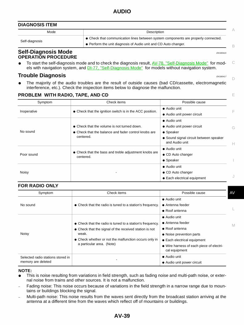
DIAGNOSIS ITEM
Self-Diagnosis Mode EKS00415
OPERATION PROCEDURE● To start the self-diagnosis mode and to check the diagnosis result, AV-78, "Self-Diagnosis Mode" for mod-
els with navigation system, and DI-77, "Self-Diagnosis Mode" for models without navigation system.
Trouble Diagnosis EKS00417
● The majority of the audio troubles are the result of outside causes (bad CD/cassette, electromagneticinterference, etc.). Check the inspection items below to diagnose the malfunction.
PROBLEM WITH RADIO, TAPE, AND CD
FOR RADIO ONLY
NOTE:● This is noise resulting from variations in field strength, such as fading noise and multi-path noise, or exter-
nal noise from trains and other sources. It is not a malfunction.– Fading noise: This noise occurs because of variations in the field strength in a narrow range due to moun-
tains or buildings blocking the signal.– Multi-path noise: This noise results from the waves sent directly from the broadcast station arriving at the
antenna at a different time from the waves which reflect off of mountains or buildings.
Mode Description
Self-diagnosis● Check that communication lines between system components are properly connected.
● Perform the unit diagnosis of Audio unit and CD Auto changer.
Symptom Check items Possible cause
Inoperative ● Check that the ignition switch is in the ACC position.● Audio unit
● Audio unit power circuit
No sound
● Check that the volume is not turned down.
● Check that the balance and fader control knobs arecentered.
● Audio unit
● Audio unit power circuit
● Speaker
● Sound signal circuit between speakerand Audio unit
Poor sound● Check that the bass and treble adjustment knobs are
centered.
● Audio unit
● CD Auto changer
● Speaker
Noisy -
● Audio unit
● CD Auto changer
● Each electrical equipment
Symptom Check items Possible cause
No sound ● Check that the radio is tuned to a station's frequency.
● Audio unit
● Antenna feeder
● Roof antenna
Noisy
● Check that the radio is tuned to a station's frequency.
● Check that the signal of the received station is notweak.
● Check whether or not the malfunction occurs only ina particular area. (Note)
● Audio unit
● Antenna feeder
● Roof antenna
● Noise prevention parts
● Each electrical equipment
● Wire harness of each piece of electri-cal equipment
Selected radio stations stored inmemory are deleted
-● Audio unit
● Audio unit power circuit

AV-40
AUDIO
FOR CASSETTE PLAYER ONLY
FOR CD ONLY
Noise Inspection EKS00418
The vehicle itself can be a source of noise if noise prevention parts or electrical equipment is malfunction.Check if noise is caused and/or changed by engine rotation, ignition switch turned to each position, and oper-ation of each piece of electrical equipment, and determine the cause.NOTE:The source of the noise can be found easily by listening to the noise while removing the fuses of electricalcomponents, one by one.
TYPE OF NOISE AND POSSIBLE CAUSE
Symptom Check items Possible cause
Cassette tape cannot be inserted.
● Check that a cassette tape is not already inserted.
● Check that the cassette has no deformation or other unusualconditions. Audio unit, Audio
unit power circuit
Cassette tape cannot be ejected.
● Check that the cassette has no deformation or other unusualconditions.
● Check that the cassette tape does not sag.
Auto reverse does not work, or the tapedirection changes in the middle of play.
● There is a problem with tape winding. Check that there is noslack or other unusual conditions.
● Check that an old cassette tape is not being used.
Audio unit
There is much noise.● Check that the cassette tape itself does not have a lot of noise, or
that the tape does not have a low recording level.
The sound is not clear.
● Check that the tune is recorded on tape with Dolby B NR OFFand played with Dolby B NR ON.
● Check that the sound quality of the cassette tape itself is notpoor.
Sound fluctuates/tape speed not correct.
● Check that there is no tape winding problem, sagging, stretching,or other unusual conditions.
● Check that there is no problem with the recording speed of thecassette tape.
No sound. ● Check that the cassette tape has been recorded on.
Symptom Check items Possible cause
The CD cannot be played.● Check that the CD is not upside down.
● Check that there is no dirt, damage, or water on the disc. ● CD Auto changer
● Audio unitThe sound skips, stops suddenly,or is distorted.
● Check that there is no dirt, damage, or water on the disc.
● Check that the trouble is not due to strong vibration.
Occurrence condition Possible cause
Occurs only when engine is ON.
A continuous growling noise occurs. The speed of thenoise varies with changes in the engine speed.
● Problem with the ignition condenser.
A whistling noise occurs while the engine speed ishigh. A booming noise occurs while the engine is run-ning and the light switch is ON.
● Problem with the alternator
The occurrence of the noise is linked with the operation of the fuel pump. ● Problem with the fuel pump condenser
Noise only occurs when variouselectrical components are oper-ating.
A cracking or snapping sound occurs with the opera-tion of various switches.
● Relay malfunction, radio malfunction
The noise occurs when various motors are operating.● Problem with the motor case ground
● Problem with the motor

AUDIO
AV-41
C
D
E
F
G
H
I
J
L
M
A
B
AV
Power Supply Circuit Inspection EKS00419
1. CHECK FUSE.
● Check that the following fuses of the Audio unit, Sub-woofer and CD Auto changer are not blown, Refer toPG-92, "FUSE BLOCK-JUNCTION BOX(J/B)" and PG-93, "FUSE AND FUSIBLE LINK BOX" .
OK or NGOK >> GO TO 2.NG >> If fuse is blown, be sure to eliminate cause of problem before installing new fuse. Refer to PG-3,
"POWER SUPPLY ROUTING" .
The noise occurs constantly, not just under certain conditions.
● Rear defogger coil malfunction
● Open circuit in printed heater
● Poor ground of antenna amplifier orantenna feeder line
A cracking or snapping sound occurs while the vehicle is being driven, especially when itis vibrating excessively.
● Problem with the ground wire of bodyparts
● Problem with ground due to part installa-tion problem
● Problem with wiring connections or ashort circuit
Occurrence condition Possible cause
Unit
Terminals
Signal name Fuse No.(+)(-)
Connector Terminal (wire color)
Audio unitM51 3(Y),4(Y) Ground Battery power 33
M51 2(P) Ground ACC power 1
CD Auto changerB31 32(Y) Ground Battery power 33
B31 36(P) Ground ACC power 1
Sub-woofer B49 4(P) Ground ACC power 1

AV-42
AUDIO
2. POWER SUPPLY CIRCUIT CHECK
Disconnect the connector. Check voltage between the following har-ness connector terminal (+) and body ground (-).
OK or NGOK >> Inspection end.NG >> Repair or replace harness.
Audio System Does Not Turn On. EKS0041A
1. SELF-DIAGNOSIS
1. Perform self-diagnosis. Refer to AV-78, "Self-Diagnosis Mode" for models with navigation system and DI-77, "Self-Diagnosis Mode" for models LCD DISPLAY without navigation system.
OK or NGOK >> Replace Audio unit.NG >> Check the malfunctioned area according to the self-diagnosis result.
Removal and Installation of Audio Unit EKS0041V
1. Remove screws (4) and remove ashtray.
Unit
Terminal No.
PowerSource
Ignitionswitch
Referencevoltage (V)
(+)
(-)Connector
Terminal(wire color)
Audio unit
M51 3(Y),4(Y) GroundBatterypower
OFFBatteryvoltage
M51 2 (P) GroundACC
powerACC
Batteryvoltage
CD Autochanger
B31 32 (Y) GroundBatterypower
OFFBatteryvoltage
B31 36 (P) GroundACC
powerACC
Batteryvoltage
Sub-woofer
B49 4(P) GroundACC
powerACC
Batteryvoltage
SKIA1579E

AUDIO
AV-43
C
D
E
F
G
H
I
J
L
M
A
B
AV
2. Remove screws (4) and remove bracket.
Removal and Installation of Door Speaker EKS004JJ
1. Remove door finisher.● EI-22, "DOOR FINISHER" in “Exterior/Interior (EI)” section.
2. Remove screws (3) and remove speaker.
Removal and Installation of Front Pillar Tweeter EKS004JK
1. Remove front pillar garnish.● EI-25, "BODY SIDE TRIM" in “Exterior/Interior (EI)” section.
2. Insert a clip remover or similar tool between the clip and front pil-lar, then remove the front-pillar tweeter.NOTE:● Remove the clip together with the front-pillar tweeter.● If it will not come off, break the clip and remove the front-pillar
tweeter.CAUTION:If clips were broken when removing front pillar tweeters,attach new clips before reinstalling to vehicle.
SKIA0310E
SKIA0001E
SKIA1613E
AV-44
AUDIO ANTENNA
AUDIO ANTENNA PFP:28200
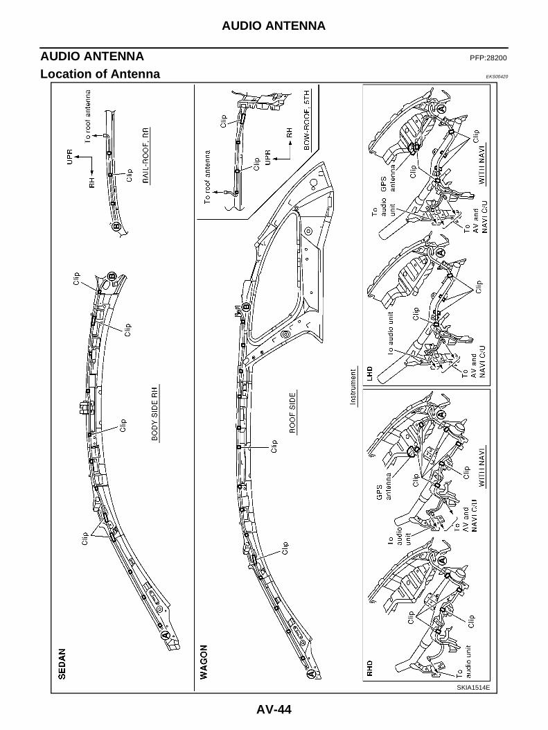
Location of Antenna EKS00420
SKIA1514E

AUDIO ANTENNA
AV-45
C
D
E
F
G
H
I
J
L
M
A
B
AV
Removal and Installation of Roof Antenna EKS00495
1. Remove headlining.● EI-32, "HEADLINING" in “Exterior/Interior (EI)” section.
2. Remove roof antenna mounting nuts, antenna plug. Thenremove roof antenna.
SKIA1614E
AV-46
TELEPHONE (PRE WIRE)
TELEPHONE (PRE WIRE) PFP:28342
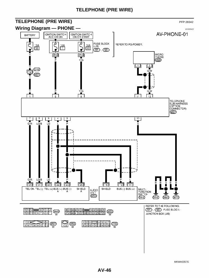
Wiring Diagram — PHONE — EKS00422
MKWA0357E

NAVIGATION SYSTEM
AV-47
C
D
E
F
G
H
I
J
L
M
A
B
AV
NAVIGATION SYSTEM PFP:25915
System Description EKS00423
The navigation system periodically calculates the vehicle's currentposition according to the following three signals: Travel distance ofthe vehicle as determined by the vehicle speed sensor, turning angleof the vehicle as determined by the gyroscope (angular velocity sen-sor), and the direction of vehicle travel as determined by the GPSantenna (GPS information).The current position of the vehicle is then identified by comparing thecalculated vehicle position with map data read from the map DVD-ROM, which is stored in the DVD-ROM drive (map-matching), andindicated on the screen with a current-location mark.
By comparing the vehicle position detection results found by theGPS and by map-matching, more accurate vehicle position data canbe used.The current vehicle position will be calculated by detecting the dis-tance the vehicle moved from the previous calculation point and itsdirection.
TRAVEL DISTANCETravel distance calculations are based on the vehicle speed sensor input signal. Therefore, the calculationmay become incorrect as the tires wear down. To prevent this, an automatic distance fine adjustment functionhas been adopted.
TRAVEL DIRECTIONChange in the travel direction of the vehicle is calculated by a gyroscope (angular velocity sensor) and a GPSantenna (GPS information). As the gyroscope and GPS antenna have both merit and demerit, input signalsfrom them are prioritized in each situation. However, this order of priority may change in accordance with moredetailed travel conditions so that the travel direction is detected more accurately.
MAP-MATCHINGMap-matching is a function that repositions the vehicle on the roadmap when a new location is judged to be the most accurate. This isdone by comparing the current vehicle position, calculated by themethod described in the position detection principle, with the roadmap data around the vehicle, read from the map DVD-ROM stored inthe DVD-ROM drive.Therefore, the vehicle position may not be corrected after the vehicleis driven over a certain distance or time in which GPS information ishard to receive. In this case, the current-location mark on the displaymust be corrected manually.NOTE:The road map data is based on data stored in the map DVD-ROM.
SKIA0370E
SEL684V
Type Advantage Disadvantage
Gyroscope (angular velocity sensor)● Can detect the vehicle's turning angle
quite accurately.
● Direction errors may accumulate when thevehicle is driven for long distances withoutstopping.
GPS antenna (GPS information)● Can detect the vehicle's travel direction
(North/South/East/West).● Correct direction cannot be detected when
the vehicle speed is low.
SEL685V
AV-48
NAVIGATION SYSTEM
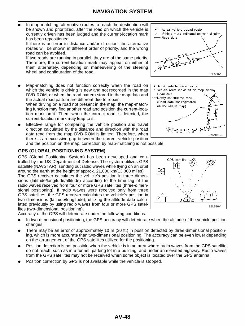
● In map-matching, alternative routes to reach the destination willbe shown and prioritized, after the road on which the vehicle iscurrently driven has been judged and the current-location markhas been repositioned.If there is an error in distance and/or direction, the alternativeroutes will be shown in different order of priority, and the wrongroad can be avoided.If two roads are running in parallel, they are of the same priority.Therefore, the current-location mark may appear on either ofthem alternately, depending on maneuvering of the steeringwheel and configuration of the road.
● Map-matching does not function correctly when the road onwhich the vehicle is driving is new and not recorded in the mapDVD-ROM, or when the road pattern stored in the map data andthe actual road pattern are different due to repair.When driving on a road not present in the map, the map-match-ing function may find another road and position the current-loca-tion mark on it. Then, when the correct road is detected, thecurrent-location mark may leap to it.
● Effective range for comparing the vehicle position and traveldirection calculated by the distance and direction with the roaddata read from the map DVD-ROM is limited. Therefore, whenthere is an excessive gap between the current vehicle positionand the position on the map, correction by map-matching is not possible.
GPS (GLOBAL POSITIONING SYSTEM)GPS (Global Positioning System) has been developed and con-trolled by the US Department of Defense. The system utilizes GPSsatellite (NAVSTAR), sending out radio waves while flying on an orbitaround the earth at the height of approx. 21,000 km(13,000 miles).The GPS receiver calculates the vehicle's position in three dimen-sions (latitude/longitude/altitude) according to the time lag of theradio waves received from four or more GPS satellites (three-dimen-sional positioning). If radio waves were received only from threeGPS satellites, the GPS receiver calculates the vehicle's position intwo dimensions (latitude/longitude), utilizing the altitude data calcu-lated previously by using radio waves from four or more GPS satel-lites (two-dimensional positioning).Accuracy of the GPS will deteriorate under the following conditions.● In two-dimensional positioning, the GPS accuracy will deteriorate when the altitude of the vehicle position
changes.● There may be an error of approximately 10 m (30 ft.) in position detected by three-dimensional position-
ing, which is more accurate than two-dimensional positioning. The accuracy can be even lower dependingon the arrangement of the GPS satellites utilized for the positioning.
● Position detection is not possible when the vehicle is in an area where radio waves from the GPS satellitedo not reach, such as in a tunnel, parking lot in a building, and under an elevated highway. Radio wavesfrom the GPS satellites may not be received when some object is located over the GPS antenna.
● Position correction by GPS is not available while the vehicle is stopped.
SEL686V
SKIA0613E
SEL526V
NAVIGATION SYSTEM
AV-49
C
D
E
F
G
H
I
J
L
M
A
B
AV
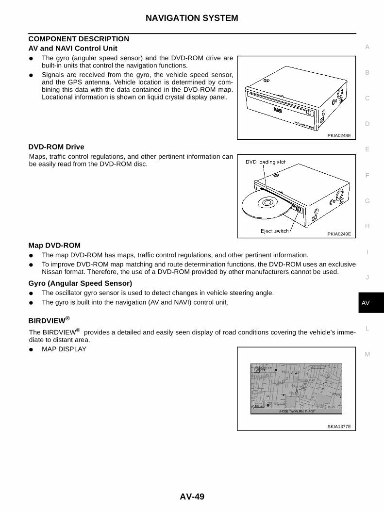
COMPONENT DESCRIPTIONAV and NAVI Control Unit● The gyro (angular speed sensor) and the DVD-ROM drive are
built-in units that control the navigation functions.● Signals are received from the gyro, the vehicle speed sensor,
and the GPS antenna. Vehicle location is determined by com-bining this data with the data contained in the DVD-ROM map.Locational information is shown on liquid crystal display panel.
DVD-ROM DriveMaps, traffic control regulations, and other pertinent information canbe easily read from the DVD-ROM disc.
Map DVD-ROM● The map DVD-ROM has maps, traffic control regulations, and other pertinent information.● To improve DVD-ROM map matching and route determination functions, the DVD-ROM uses an exclusive
Nissan format. Therefore, the use of a DVD-ROM provided by other manufacturers cannot be used.
Gyro (Angular Speed Sensor)● The oscillator gyro sensor is used to detect changes in vehicle steering angle.● The gyro is built into the navigation (AV and NAVI) control unit.
BIRDVIEW®
The BIRDVIEW® provides a detailed and easily seen display of road conditions covering the vehicle's imme-diate to distant area.● MAP DISPLAY
PKIA0248E
PKIA0249E
SKIA1377E

AV-50
NAVIGATION SYSTEM
● BIRDVIEW®
Description● Display area: Trapezoidal representation showing approximate
distances (Wn, D, and Wd).● Ten horizontal grid lines indicate display width while six vertical
grid lines indicate display depth and direction.● Drawing line area shows open space, depth, and immediate
front area. Each area is to a scale of approximately 5:6:25.● Pushing the “ZOOM IN” button during operation displays the
scale change and the view point height on the left side of thescreen.The height of the view point increases or decreases when“ZOOM” or “WIDE” is selected with the joystick.
MAP DISPLAYFunction of each icon is as follows:1. Azimuth indication.2. Position marker.– The tip of the arrow shows the current position. The shaft of the
arrow indicates the direction in which the vehicle is traveling.3. GPS reception signal (indicates current reception conditions).4. Distance display (shows the distance in a reduced scale).
SKIA1378E
SEL691V
SKIA1379E

NAVIGATION SYSTEM
AV-51
C
D
E
F
G
H
I
J
L
M
A
B
AV
FUNCTION OF MULTIFUNCTION SWITCHDisplay With Pushed “DEST” Switch● Easy Mode
● Expert Mode
The Function of Each Icon Is as Follows:
Display With Pushed “ROUTE” Switch● Easy Mode
SKIA1623E
SKIA1381E
IconMODE
DescriptionEasy Expert
Address Book × Favorite place can be saved to memory.
Address/Street × × The destination can be searched from the address.
Point of Interest (POI) × × The destination of favorite facility can be searched.
Previous Dest. × The previous ten destinations stored in memory are displayed.
Intersection × The destination can be searched from the intersection.
City Center × The destination can be searched from city name.
Map × The destination can be searched from the map.
Home × Sets the home as a destination.
Help × Explanation of Navigational functions appear on the Display.
SKIA1382E

AV-52
NAVIGATION SYSTEM
● Expert Mode
The Function of Each Icon Is as Follows:
*: When destinations have been entered, route guidance has been turned OFF or destination has been reached, “Route Info.” and “EditRoute” are not displayed.
Display With Pushed “SETTING” Switch
The Function of Each Icon Is as Follows:
SKIA1383E
IconMODE
DescriptionEasy Expert
Quick Stop × × The selected facility is set as the destination or waypoint.(Route guidance has been turned OFF or the destination has been reached)
Where am I? × × Next, current and previous street names can be displayed.
Route Info.* ×
The following items can be set.
● Complete Route
● Turn List
● Route Simulation
(Displayed only when the destination area has been set.)
Edit Route* ×Change the destination or add the transit points of the route set in the route guide. (Dis-played only when the automatic reroute function has been turned OFF and the recom-mended route is not followed.)
Route Calculation × This key is used to start the route calculation after all the settings are completed.
Help × Explanation of Navigational functions appear on the Display.
SKIA1384E
Icon Description
AudioSound quality can be adjusted, and also ON/OFF setting of switch beep sound can be performed.Noise Compensation ON/OFF setting can be performed.
Display Settings of display can be performed.
LanguageLanguage can be selected for the display and voice guidance.Use the program CD-ROM disc to change the language.
Navigation Settings and adjusting of navigation can be performed.
Navigation Expert Mode Easy Mode and Expert Mode can be switched.
Guidance Volume The volume and/or on/off of voice prompt can be controlled by the joystick.
Help Explanation of Navigational Functions Appear on the Display.

NAVIGATION SYSTEM
AV-53
C
D
E
F
G
H
I
J
L
M
A
B
AV
“LANGUAGE” mode● Select one of the languages which appear on the screen.NOTE:Languages that do not appear on the screen must be loaded fromprogram disk.
Navigation SettingsHow To Perform Navigation Settings1. Start the engine.2. Push “SETTING” switch.3. Select “NAVIGATION”.
SKIA1399E
SKIA1385E

AV-54
NAVIGATION SYSTEM
Application Items
“VIEW” MODE1. Select “Bird View®” or “Plan view” icon.
● To open the map screen display with Bird View®, select “BirdView®”.
● To open the map screen display with Plan View, select “PlanView”.
“HEADING” MODE● To display North up, select “North up”.● To display the car heading up, select “Heading up”.
Icon DescriptionReference
page
View Map display mode can be switched. AV-54
HeadingHeading of the map display can be customized for either north heading or theactual driving direction of the vehicle.
AV-54
Nearby Display IconsIcons of facilities can be displayed.Facilities to be displayed can be selected from the variety selections.
AV-55
Save Current Location Current vehicle location can be registered in Address Book. AV-55
Edit Address Book Address Book can be edited. AV-55
Clear Memory Address Book, Previous destination or Avoid area can be deleted. AV-55
Auto Re-route ON/OFF ON/OFF of Auto Re-route can be switched. AV-56
Quick Stop Customer Setting One facility of your selection can be added to your Quick Stop. AV-56
Set Average speed for EstimatedJourney Time
Average vehicle speed can be set to calibrate estimated journey time for thedestination.
AV-56
GPS Information
The GPS data includes longitude, latitude and altitude (distance above sealevel) of the present vehicle position, and current date and time for the area inwhich the vehicle is being driven.Also indicated are the GPS reception conditions and the GPS satellite position.
AV-56
Avoid Area Setting A particular area can be avoided when routing. -
Tracking on/off Tracking to the present vehicle position can be displayed. AV-57
Adjust Current LocationCurrent location of position marker can be adjusted. Direction of position markeralso can be calibrated when heading direction of the vehicle on the display isnot matched with the actual direction.
AV-57
SKIA0554E
SKIA0561E

NAVIGATION SYSTEM
AV-55
C
D
E
F
G
H
I
J
L
M
A
B
AV
“NEARBY DISPLAY ICONS” MODE● Select an icon to display on the map screen.
“SAVE CURRENT LOCATION” MODE● The current vehicle location can be registered in “Address
Book”.NOTE:“Address Book” can store 50 items max.
“EDIT ADDRESS BOOK” MODE● Edit the items registered in Address Book.
“CLEAR MEMORY” MODE● To delete all the stored places in “Address Book”, “Avoid Area”
and “Previous Dest”, select “Yes”.
SKIA1394E
SKIA1388E
SKIA0560E
SKIA0566E

AV-56
NAVIGATION SYSTEM
“AUTO RE-ROUTE” MODE● To Perform the auto re-route of route, select “ON”.● Not to Perform the auto re-route of route, select “OFF”.
“QUICK STOP CUSTOMER SETTINGS” MODE● Select a category for the “Quick Stop” menu.
“SET AVERAGE SPEED FOR ESTIMATED JOURNEY TIME” MODE● Set the average vehicle speed to calibrate the estimated journey
time for the destination.● Set three items; “Freeway”, “Main Roads”, and “Ordinary
Roads”.
“GPS INFORMATION” MODE● Latitude, longitude, altitude, astrometric state, and satellite loca-
tion are displayed as GPS information.NOTE:Altitude is displayed only in three-dimensional status.
SKIA0558E
SKIA1389E
SKIA1397E
SKIA0555E

NAVIGATION SYSTEM
AV-57
C
D
E
F
G
H
I
J
L
M
A
B
AV
“TRACKING” MODE● To leave no trail on the map, select “Off”.● To leave a trail in the map, select “On”.NOTE:When a trail display is turned OFF, trail data is erased from the mem-ory.
“ADJUST CURRENT LOCATION” MODE1. Select an icon “right” or “left” to calibrate the heading direction.
(Arrow marks will rotate corresponding to the calibration key.)
2. Select “Set”. Then the vehicle mark will be matched to the arrowmark.
GUIDE VOLUME SETTINGDescriptionFollowing voice guidance setting can be changed.
Activation/Deactivation Setting● The voice prompt can be turned on/off by pressing the “Guidance Volume” button.
Voice Volume Setting● Volume of the voice can be controlled by bending the joystick to left/right.
SKIA0559E
SKIA1395E
SKIA1396E
SKIA1400E

AV-58
NAVIGATION SYSTEM
NATS NAVI LINKDescriptionThe link with the NATS IMMU implies that the AV and NAVI control unit can basically only be operated if con-nected to the matching NATS IMMU to which the AV and NAVI control unit was initially fitted on the productionline.The Navigation system does not operate because it is judged that the code collation with NATS IMMU is illegalwhen the control unit of other cars is installed.
Precautions for AV and NAVI Control Unit Replacement EKS00424
● When replacing the AV and NAVI control unit, eject the map DVD-ROM before disconnecting the battery.● The AV and NAVI control unit has the following information stored in its memory. Record the memory con-
tents before replacing the control unit, and input them in the new unit as necessary.
NOTE:Only removing the battery does not erase the memory.
<RADIO> ● Preset frequency
● Area for indicating station, selection of overlapped stations
<CD> ● Program status
<Sound quality> ● Volume balance memory set values
● Equalizer memory set values
<Image quality> ● Brightness of light when ON/OFF
● Dimming switching
● Display color switching
<Navigation mode> ● Latest status (map screen/bird view®, reduced scale, rotation angle ofmap screen, route guide ON/OFF, track ON/OFF, etc.)
● Current position
● Destination, passing point 1 - 5
● Registered places, their names, etc.

NAVIGATION SYSTEM
AV-59
C
D
E
F
G
H
I
J
L
M
A
B
AV
Component Parts Location EKS00425
SKIA1401E

AV-60
NAVIGATION SYSTEM
Location of Antenna EKS00426
Refer to AV-44, "Location of Antenna" .

NAVIGATION SYSTEM
AV-61
C
D
E
F
G
H
I
J
L
M
A
B
AV
Schematic EKS00427
MKWA0087E
AV-62
NAVIGATION SYSTEM
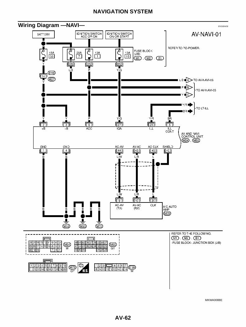
Wiring Diagram —NAVI— EKS00428
MKWA0088E

NAVIGATION SYSTEM
AV-63
C
D
E
F
G
H
I
J
L
M
A
B
AV
MKWA0089E

AV-64
NAVIGATION SYSTEM
MKWA0090E

NAVIGATION SYSTEM
AV-65
C
D
E
F
G
H
I
J
L
M
A
B
AV
MKWA0091E
AV-66
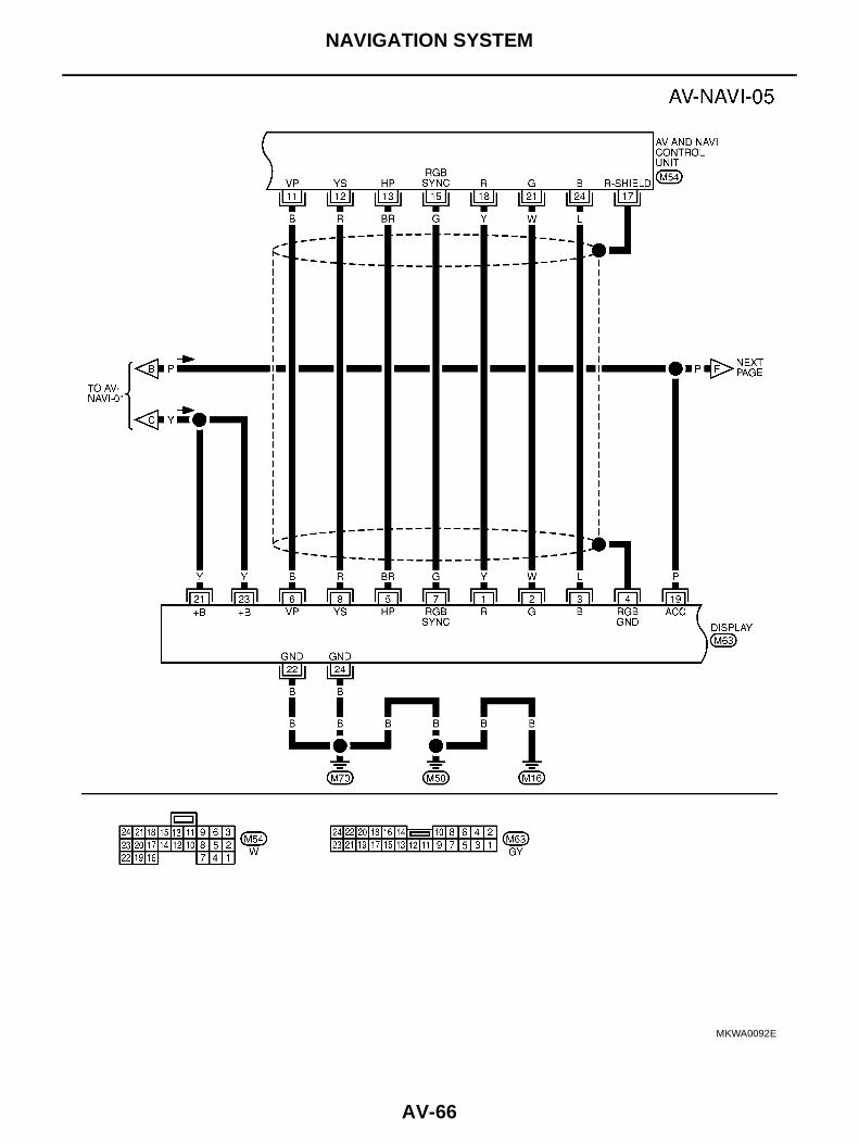
NAVIGATION SYSTEM
MKWA0092E

NAVIGATION SYSTEM
AV-67
C
D
E
F
G
H
I
J
L
M
A
B
AV
MKWA0093E

AV-68
NAVIGATION SYSTEM
Schematic For AV Communication Line EKS004N4
MKWA0200E

NAVIGATION SYSTEM
AV-69
C
D
E
F
G
H
I
J
L
M
A
B
AV
Wiring Diagram — COMM — EKS0044Z
MKWA0205E

AV-70
NAVIGATION SYSTEM
MKWA0206E

NAVIGATION SYSTEM
AV-71
C
D
E
F
G
H
I
J
L
M
A
B
AV
MKWA0207E

AV-72
NAVIGATION SYSTEM
Terminals and Reference Value for AV and NAVI Control Unit EKS00429
● For measurements made with IGN switch ON, if possible, measure with engine running to prevent batterydischarge.
● Use a circuit tester and oscilloscope for measurement.
Terminal No.(wire color)
ItemSignalinput/output
Condition
Voltage Example of symptom
+ -Ignitionswitch
Operation
1 (B) ground Ground - ON - Approx. 0V -
2 (Y)ground
Batterypower
Input OFF - Battery voltageSystem does not
work properly.3 (Y)
4 (B) ground Ground - ON - Approx. 0V -
5 (BR) groundIllumination
ground- ON - Approx. 0V -
6 (P) ground ACC signal Input ACC - Battery voltageSystem does not
work properly.
7 (BR) 8 (Y)voice guide
signalOutput ON
Press the“voice”switch.
Only route guide andoperation guide are
not heard.
9(B) -Shieldground
- - - - -
11 (B) 17Vertical syn-chronizing
signalInput ON -
Superimposedscreen is rolling.
12 (R) 17RGB area
signalOutput ON
Press the“info”switch.
RGB screen is notshown.
13(BR)
17Horizontal
synchroniz-ing signal
Input ON
Select“ Display” in“Setting” mode and
display the rear-view picture on the
screen.
Superimposedscreen is not shown.
SKIA0171E
SKIA0161E
SKIA0162E
SKIA0163E
NAVIGATION SYSTEM
AV-73
C
D
E
F
G
H
I
J
L
M
A
B
AV
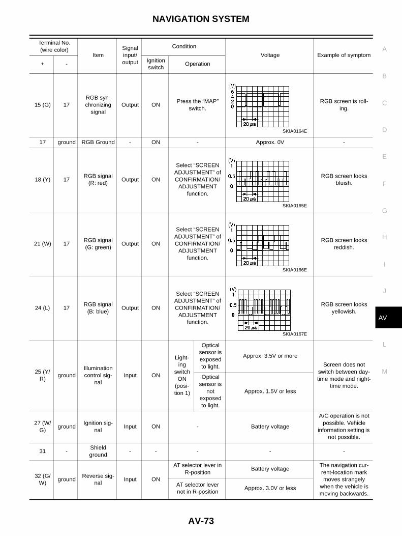
15 (G) 17RGB syn-chronizing
signalOutput ON
Press the “MAP”switch.
RGB screen is roll-ing.
17 ground RGB Ground - ON - Approx. 0V -
18 (Y) 17RGB signal
(R: red)Output ON
Select “SCREENADJUSTMENT” ofCONFIRMATION/
ADJUSTMENTfunction.
RGB screen looksbluish.
21 (W) 17RGB signal(G: green)
Output ON
Select “SCREENADJUSTMENT” ofCONFIRMATION/
ADJUSTMENTfunction.
RGB screen looksreddish.
24 (L) 17RGB signal
(B: blue)Output ON
Select “SCREENADJUSTMENT” ofCONFIRMATION/
ADJUSTMENTfunction.
RGB screen looksyellowish.
25 (Y/R)
groundIlluminationcontrol sig-
nalInput ON
Light-ing
switchON
(posi-tion 1)
Opticalsensor isexposedto light.
Approx. 3.5V or more
Screen does notswitch between day-time mode and night-
time mode.
Opticalsensor is
notexposedto light.
Approx. 1.5V or less
27 (W/G)
groundIgnition sig-
nalInput ON - Battery voltage
A/C operation is notpossible. Vehicle
information setting isnot possible.
31 -Shieldground
- - - - -
32 (G/W)
groundReverse sig-
nalInput ON
AT selector lever inR-position
Battery voltageThe navigation cur-rent-location markmoves strangely
when the vehicle ismoving backwards.
AT selector levernot in R-position
Approx. 3.0V or less
Terminal No.(wire color)
ItemSignalinput/output
Condition
Voltage Example of symptom
+ -Ignitionswitch
Operation
SKIA0164E
SKIA0165E
SKIA0166E
SKIA0167E

AV-74
NAVIGATION SYSTEM
33 (L/B)
groundVehicle
speed signal(2-pulse)
Input ONWhen vehicle
speed is approx. 40km/h (25MPH)
Navigation current-location mark doesnot indicate the cor-
rect position.
34 (R) groundCommunica-
tion signal(AV - ME)
Output ONDisplay the vehicleinformation screen.
Clock cannot beadjusted.
Vehicle informationscreen is not shown.
35 (G) groundCommunica-
tion signal(ME - AV)
Input ON
Perform varioussettings on the vehi-
cle informationscreen.
Clock cannot beadjusted.
Vehicle informationscreen is not shown.
40 -Shieldground
- - - - -
43 (L/R)
groundA/C commu-nication sig-
nal (AV - AC)Output ON -
A/C operation is notpossible.
44 (L/W)
groundA/C commu-nication sig-
nal (AV - AC)Input ON
-A/C status is not indi-
cated correctly.
45 (L) groundA/C clock
signalInput ON -
A/C status is not indi-cated correctly.
46(B) -Shieldground
- - - - -
Terminal No.(wire color)
ItemSignalinput/output
Condition
Voltage Example of symptom
+ -Ignitionswitch
Operation
ELF1080D
SKIA0169E
SKIA0170E
SKIA0172E
SKIA0173E
SKIA0174E
NAVIGATION SYSTEM
AV-75
C
D
E
F
G
H
I
J
L
M
A
B
AV
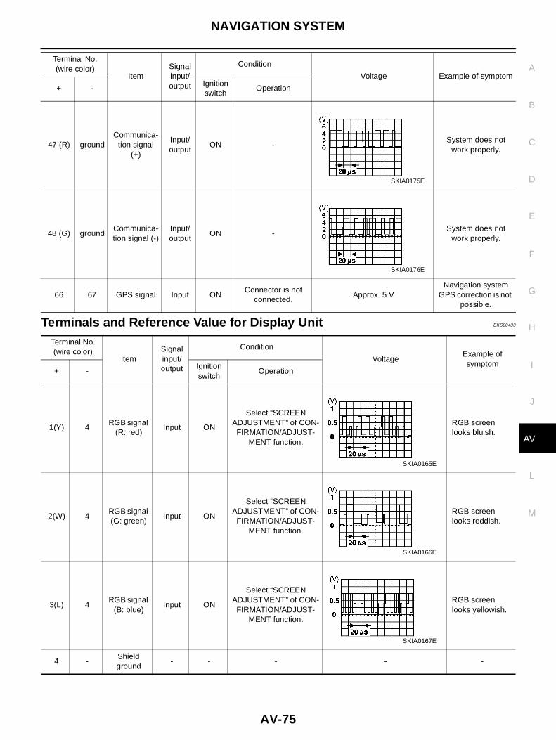
Terminals and Reference Value for Display Unit EKS00433
47 (R) groundCommunica-
tion signal(+)
Input/output
ON -System does not
work properly.
48 (G) groundCommunica-tion signal (-)
Input/output
ON -System does not
work properly.
66 67 GPS signal Input ONConnector is not
connected.Approx. 5 V
Navigation systemGPS correction is not
possible.
Terminal No.(wire color)
ItemSignalinput/output
Condition
Voltage Example of symptom
+ -Ignitionswitch
Operation
SKIA0175E
SKIA0176E
Terminal No.(wire color)
ItemSignalinput/output
Condition
VoltageExample ofsymptom
+ -Ignitionswitch
Operation
1(Y) 4RGB signal
(R: red)Input ON
Select “SCREENADJUSTMENT” of CON-
FIRMATION/ADJUST-MENT function.
RGB screenlooks bluish.
2(W) 4RGB signal(G: green)
Input ON
Select “SCREENADJUSTMENT” of CON-
FIRMATION/ADJUST-MENT function.
RGB screenlooks reddish.
3(L) 4RGB signal
(B: blue)Input ON
Select “SCREENADJUSTMENT” of CON-
FIRMATION/ADJUST-MENT function.
RGB screenlooks yellowish.
4 -Shieldground
- - - - -
SKIA0165E
SKIA0166E
SKIA0167E

AV-76
NAVIGATION SYSTEM
5(BR) 4Horizontal
synchroniz-ing signal
Output ON
Select“ Display” in “Set-ting” mode and displaythe rear view picture on
the screen.
Superimposedscreen is notshown.
6(B) 4Vertical
synchroniz-ing signal
Output ON -Superimposedscreen is rolling.
7(G) 4RGB syn-chronizing
signalInput ON Press the “MAP” switch.
RGB screen isrolling.
8(R) 4RGB area
signalInput ON Press the “info” switch.
RGB screen isnot shown.
12(W)
groundCommuni-cation sig-
nal (-)
Input/output
ON -System does notwork properly.
13(B) groundCommuni-cation sig-
nal (+)
Input/output
ON -System does notwork properly.
14 -Shieldground
- - - - -
19(P) ground ACC signal Input ACC - Battery voltageScreen is notshown.
Terminal No.(wire color)
ItemSignalinput/output
Condition
VoltageExample ofsymptom
+ -Ignitionswitch
Operation
SKIA0163E
SKIA0161E
SKIA0164E
SKIA0162E
SKIA0176E
SKIA0175E

NAVIGATION SYSTEM
AV-77
C
D
E
F
G
H
I
J
L
M
A
B
AV
Terminals and Reference Value for Multifunction Switch EKS00434
21(Y)ground
Batterypower
Input OFF - Battery voltageScreen is notshown.23(Y)
22(B) ground Ground - ON - Approx. 0V –
24(B) ground Ground - ON - Approx. 0V –
Terminal No.(wire color)
ItemSignalinput/output
Condition
VoltageExample ofsymptom
+ -Ignitionswitch
Operation
Terminal No.(wire color)
ItemSignalinput/output
Condition
VoltageExample ofsymptom
+ -Ignitionswitch
Operation
1(B) ground Ground - ON - -All operationsdo not work.
2(BR) groundIlluminationcontrol sig-nal
Input ONIllumination control switch isoperated by lighting switchin 1st position.
Changes between approx. 0and approx. 12V.
MultifunctionSwitch illumi-nation cannotbe controlled.
4(Y/R) groundIlluminationcontrol sig-
nalInput ON
Lightingswitch ON(position 1)
Optical sensoris exposed to
light.Approx. 3.5V or more
Screen doesnot switchbetween day-time modeand nighttimemode.
Optical sensoris not exposed
to light.Approx. 1.5V or less
6(P) ground ACC Input ACC - Battery voltageAll operationsdo not work.
9(G/B)
groundRear defog-ger ON sig-
nalOutput ON
Press rear defogger switch. Approx. 5V Rear defog-ger does notwork.- Approx. 0V
10(L/R)
groundRear defog-ger indicator
signalInput ON
Turn rear defogger switchON.
Battery voltageRear defog-ger indicatordoes not illu-minate.OFF Approx. 0V
11(L)12(B)
groundCommuni-cation sig-
nal (+)
Input/output
ON -System doesnot work prop-erly.
13(P)14(W)
groundCommuni-cation sig-
nal (-)
Input/output
ON -System doesnot work prop-erly.
1516
groundShieldground
- ON - - -
SKIA0175E
SKIA0176E

AV-78
NAVIGATION SYSTEM
Self-Diagnosis Function EKS00435
DESCRIPTION● Diagnosis function consists of the self-diagnosis mode performed automatically and the confirmation/
adjustment mode operated manually.● Self-diagnosis mode checks connections between all units and performs individual unit diagnosis for all
units in system. Results are displayed on LCD display.● Check/adjustment mode is used to perform trouble diagnosis that require operation and judgment by an
operator (trouble that cannot be automatically judged by the system), to check/change the set value, andto display the error record of the navigation system.
SELF-DIAGNOSIS ITEM
Self-Diagnosis Mode EKS00436
OPERATION PROCEDURE1. Start the engine.2. Turn the audio system off.3. While pressing the “INFO” switch, turn the volume control dial
clockwise or counterclockwise for 30 clicks or more. (When theself-diagnosis mode is started, a short beep will be heard.)● Shifting from current screen to previous screen is performed
by pressing “BACK” switch.
Mode Diagnosis content
Self-diagnosis
● Control unit diagnosis (DVD-ROM drive will not be diagnosed when nomap DVD-ROM is in it.)
● Performs diagnosis of connections between C/U and GPS antenna andbetween C/U and all units.
Confirmation/adjustment
DisplayColor tone and shading of the screen can be checked by the display of acolor bar and a gray scale.
Vehicle signalsThe following signals can be diagnosed: vehicle speed, parking brake, light,IGN (IGN SW), and reverse.
History of ErrorsDisplays the navigation system-related problems that occurred in the pastand the number of their occurrence. When a trouble symptom is selected,the time and place of the latest occurrence will be shown.
Auto Climate ControlAll A/C screen displays on LCD monitor and the A/C SW indicator lamp areilluminated.
Navigation
Display Longitude &Latitude
Display the map. Use the joystick to adjust position. Longitude and latitudewill be displayed.
Angle adjustmentCorrects difference between actual turning angle of a vehicle and turningangle of the car mark on the display.
Distance adjustmentCorrects difference between the current-location mark on the display andactual position of the vehicle.
Initialize LocationLocation memorized by AV and NAVI control unit can be initialized in thismode.
Service Service schedule can be changed in this mode.
SKIA1402E

NAVIGATION SYSTEM
AV-79
C
D
E
F
G
H
I
J
L
M
A
B
AV
4. The initial trouble diagnosis screen will be shown, and items“SELF-DIAGNOSIS” and “CONFIRMATION/ADJUSTMENT” willbecome selective.
5. Perform self-diagnosis by selecting the “SELF-DIAGNOSIS”.● Self-diagnosis subdivision screen will be shown and the oper-
ation enters the self-diagnosis mode.● A bar graph shown below the self-diagnosis subdivision
screen indicates progress of the diagnosis.
6. When the self-diagnosis completes, optional part confirmation screen will be shown.● When connection of an optional part is judged faulty, a screen to check if the optional part is actually fit-
ted on the vehicle or not will be shown. When fitted, select the switch of the part on the screen andpress “END”. Then the “Self-diagnosis” screen will be shown.
● When the optional part is connected normally, the switch forthe part will not appear on the screen.
7. On the “Self-diagnosis” screen, each unit name will be coloredaccording to the diagnosis result, as follows.
● If several malfunctions are present in a unit, color of its switchon the screen will be either red, yellow, or gray, determined bythe malfunction of the highest priority.
SKIA0381E
SKIA0382E
SKIA1403E
Green : No malfunctioning.
Yellow : Cannot be judged by self-diagnosis results.
Red : Unit is malfunctioning.
Gray : Diagnosis has not been done.
SKIA1404E

AV-80
NAVIGATION SYSTEM
8. Select a switch on the “Self-diagnosis” screen and comments forthe diagnosis results will be shown.● When the switch is green, the following comment will be
shown. “Self-diagnosis was successful. Further diagnosis andadjustments are recommended. Follow the “confirmation andadjustments” menu or refer to the service manual”.
● When the switch is yellow, the following comment will beshown. “Connection to the following unit is abnormal. See theservice manual for further details”.
● When the switch is red, the following comment will be shown.“Center Control Unit is abnormal”.
● When the switch is gray, the following comment will be shown. “Self-diagnosis for DVD-ROM DRIVERof NAVI was not conducted because no DVD-ROM was available”.
DIAGNOSIS CHART1. Find applicable diagnosis number from chart.2. Find possible causes from diagnosis number chart. Perform check with AV-69, "Wiring Diagram — COMM
—" .3. Turn ignition switch ON, then perform self-diagnosis again.
CAUTION:If multifunction switch is malfunctioning, self-diagnosis mode cannot be started.
DIAGNOSIS NUMBER CHART
SKIA1516E
Screen switchDiagnosis No.
Switch color Control unit Display Audio unit CD auto changer GPS antenna
Red × Diagnosis 1
Gray × Diagnosis 2
Yellow
× Diagnosis 3
× Diagnosis 4
× × Diagnosis 5
× × × Diagnosis 6
× Diagnosis 7
× × Diagnosis 8
Diagnosis No. Possible causes
Diagnosis 1 Control unit (AV and NAVI C/U) is malfunctioning.
Diagnosis 2 AV and NAVI C/U determines that no map DVD-ROM is inserted.
Diagnosis 3
If "DVD-ROM is malfunctioning. Check disc." is displayed:
1. Remove inserted map DVD-ROM and check that it is correct special DVD-ROM.
2. Check that there is no dirt, damage, or warping on removed DVD-ROM.
3. If above checks reveal nothing unusual, insert another map DVD-ROM with same contents. Then check whethersame diagnosis result is obtained when "Self-diagnosis" is performed. If result is same, AV and NAVI C/U is mal-functioning. If not same, map DVD-ROM should be replaced.
Diagnosis 4"DVD-ROM or DVD-ROM driver in C/U is malfunctioning. Follow maintenance procedures to diagnose." is displayed:Perform check as described in Diagnosis 3.
Diagnosis 5● Display power supply or ground line
● AV communication line between Display and multifunction switch
Diagnosis 6 Audio unit power supply or ground line

NAVIGATION SYSTEM
AV-81
C
D
E
F
G
H
I
J
L
M
A
B
AV
CONFIRMATION/ADJUSTMENT Mode EKS00437
OPERATION PROCEDURE1. Start the engine.2. Turn the audio system off.3. While pressing the “INFO” switch, turn the volume control dial
clockwise or counterclockwise for 30 clicks or more. (When theself-diagnosis mode is started, a short beep will be heard.)● Shifting from current screen to previous screen is performed
by pressing “BACK” switch.
4. The initial trouble diagnosis screen will be shown, and items“SELF-DIAGNOSIS” and “CONFIRMATION/ADJUSTMENT” willbecome selective.
5. When “CONFIRMATION/ADJUSTMENT” is selected on the ini-tial trouble diagnosis screen, the operation will enter the CON-FIRMATION/ADJUSTMENT mode. In this mode, check andadjustment of each item will become possible.
6. Select each switch on “CONFIRMATION/ADJUSTMENT”screen to display the relevant diagnosis screen.
Diagnosis 7 CD auto changer power supply and ground circuit, Communication line between CD auto changer and audio unit
Diagnosis 8
GPS antenna system
1. Visually check for open circuit in GPS antenna coaxial cable.
2. Disconnect GPS antenna connector and check AV and NAVI C/U outputs approx. 5V. If there is no voltage, AV andNAVI C/U is malfunctioning. If there is, replace GPS antenna. If connection is inoperative after performing self-diag-nosis again, AV and NAVI C/U is malfunctioning.
Diagnosis No. Possible causes
SKIA1402E
SKIA0381E
SKIA1405E

AV-82
NAVIGATION SYSTEM
DISPLAY
● When RGB signal error occurred in the RGB system, tone of the color bar will change as follows.
● When the color of the screen looks unusual, AV-93, "Color of RGB Image Is Not Proper." .
VEHICLE SIGNALS● A comparison check can be made of each actual vehicle signal
and the signals recognized by the system.
● If vehicle speed is NG, AV-89, "Vehicle Speed Signal Check" .
SKIA0362E
R (red) signal error : Screen looks bluish
G (green) signal error : Screen looks yellowish
B (blue) signal error : Screen looks reddish
SKIA1406E
Diagnosis item Display Condition Remarks
Vehicle speed
ON Vehicle speed > 0 km/h (0 MPH)Changes in indication may be delayed byapprox. 1.5 seconds. This is normal.
OFF Vehicle speed = 0 km/h (0 MPH)
- Ignition switch in ACC position
LightsON Lighting switch ON
-OFF Lighting switch OFF
IGNON Ignition switch ON
-OFF Ignition switch ACC or OFF
Reverse
ON Selector lever in R-positionChanges in indication may be delayed byapprox. 1.5 seconds. This is normal.
OFF Selector lever in other than R-position
- Ignition switch in ACC position

NAVIGATION SYSTEM
AV-83
C
D
E
F
G
H
I
J
L
M
A
B
AV
● If light is NG, AV-90, "Illumination Control Signal Check" .● If IGN is NG, AV-90, "Ignition Signal Check" .● If reverse is NG, AV-91, "Reverse Signal Check" .
NAVIGATIONDisplay Longitude & Latitude● Adjust the pointer with using the joystick and touch “Set”.
● The longitude and latitude are displayed.
Angle Adjustment● Adjusts turning angle output detected by the gyroscope.
Speed Calibration● During normal driving, distance error caused by tire wear and
tire pressure change is automatically adjusted for by the auto-matic distance correction function. This function, on the otherhand, is for immediate adjustment, in cases such as driving withtire chain fitted on tires.
SKIA1616E
SKIA1617E
SKIA1517E
SKIA0365E

AV-84
NAVIGATION SYSTEM
Initialize LocationDescription● Location data for GPS in the Center control unit is initialized in Europe by this mode. Then it is possible for
Center control unit to receive GPS signals for short time.
How to perform “Initialize location” mode1. Select “Initialize Location”, and push “ENTER”.
2. A message “Please wait.” is displayed and then backs toanother display of “Confirmation/Adjustment” mode.
NOTE:● To continue GPS initialized operation, operate as follows back to
“Map” screen.– Push "BACK" button twice.– Push "MAP" button.● After above operation, GPS indicator changes to green color
within half a minute, unless improper GPS located condition.● This operation should be performed in outside field.
HISTORY OF ERRORS
DIAGNOSIS BY HISTORY OF ERRORSThe “Self-diagnosis” results indicate whether an error occurred during the period from when the ignition switchis turned to ON until “Self-diagnosis” is completed.If an error occurred before the ignition switch was turned to ON and does not occur again until the “Self-diag-nosis” is completed, the diagnosis result will be judged normal. Therefore, those errors in the past, which can-not be found by the “Self-diagnosis,” must be found by diagnosing the “History of Errors”.
SKIA1618E
SKIA1619E
SKIA1518E

NAVIGATION SYSTEM
AV-85
C
D
E
F
G
H
I
J
L
M
A
B
AV
The History of Errors displays the time and place of the most recent occurrence of that error. However, takenote of the following points.● Correct time of the error occurrence may not be displayed when the GPS antenna substrate within the AV
and NAVI control unit has malfunctioned.● Place of the error occurrence is represented by the position of the current-location mark at the time when
the error occurred. If the current-location mark has deviated from the correct position, then the place ofthe error occurrence max be located correctly.
● The maximum number of occurrences which can be stored is 50. For the 51st and later occurrences, thedisplayed number remains 50.
When a reproducible malfunction occurred but its cause cannot be identified because several errors arepresent, record the item, number and place (longitude/latitude) of error occurrence (or delete the History ofErrors), then turn the ignition switch from OFF to ON to reproduce the malfunction. Check the History of Errorsto find the items which show an increased number of occurrences, and diagnose the item.
Error itemPossible causes
Example of symptomAction/symptom
Gyro sensordisconnected
Communications malfunction between NAVI control unit and inter-nal gyro
● Navigation location detection performancehas deteriorated.(Angular velocity cannot be detected.)
● Perform the self-diagnosis.
● When the AV and NAVI control unit is judged normal by self-diagnosis, the symptom may be intermittent, caused by strongradio interference.
GPS discon-nected
Communication error between AV and NAVI control unit and inter-nal GPS substrate ● Navigation location detection performance
has deteriorated.(Location correction using GPS is not per-formed.)
● GPS receiving status remains gray.
● Perform the self-diagnosis.
● When the AV and NAVI control unit is judged normal by self-diagnosis, the symptom may be intermittent, caused by strongradio interference.
GPS trans-mission cablemalfunction
Malfunctioning transmission wires to AV and NAVI control unit andinternal GPS substrate
● During self-diagnosis, GPS diagnosis is notperformed.
● Perform the self-diagnosis.
● When the AV and NAVI control unit is judged normal by self-diagnosis, the symptom may be intermittent, caused by strongradio interference.
GPS inputline connec-tion error
Malfunctioning receiving wires to AV and NAVI control unit andinternal GPS substrate ● Navigation location detection performance
has deteriorated.(Location correction using GPS is not per-formed.)
● GPS receiving status remains gray.
● Perform the self-diagnosis.
● When the AV and NAVI control unit is judged normal by self-diagnosis, the symptom may be intermittent, caused by strongradio interference.
GPS TCX0overGPS TCX0under
Oscillating frequency of the GPS substrate frequency synchroniz-ing oscillation circuit exceeded (or below) the specification ● Navigation location detection performance
has deteriorated.(Location correction using GPS is not per-formed.)
● GPS receiving status remains gray.
● Perform the self-diagnosis.
● When the AV and NAVI control unit is judged normal by self-diagnosis, the symptom may be intermittent, caused by strongradio interference, or the control unit may have been subjectedto excessively high or low temperatures.
GPS ROMmalfunctionGPS RAMmalfunction
Contents of ROM (or RAM) in GPS substrate are malfunctioning. ● Location detection accuracy of the navigationsystem will deteriorate, depending on thefailed area in the memory, because GPS can-not make correct positioning.(Location correction using GPS is not per-formed.)
● Perform the self-diagnosis.
● When the AV and NAVI control unit is judged normal by self-diagnosis, the symptom may be intermittent, caused by strongradio interference.

AV-86
NAVIGATION SYSTEM
AUTO CLIMATE CONTROL● “ATC Automatic Air Conditioner” ATC-41, "Self-diagnosis Function" for the details.
SERVICE● To set Service schedule, change Journey distance with joystick.
At the same time, the marker of journey distance will be moved.
GPS RTCmalfunction
Clock IC in GPS substrate is malfunctioning. ● Correct time may not be displayed.
● After the power is turned on, the systemalways takes some time until GPS positioningbecomes possible. (The GPS receiver startspositioning without re-collecting the whole sat-ellite information when it judged the datastored in the receiver is correct.)
● Correct time of error occurrence may not bestored in the “History of Errors”.
● Perform the self-diagnosis.
● When the AV and NAVI control unit is judged normal by self-diagnosis, the symptom may be intermittent, caused by strongradio interference.
GPS antennadisconnected
Malfunctioning connection between GPS substrate in AV andNAVI control unit and GPS antenna. ● Navigation location detection performance
has deteriorated.(Location correction using GPS is not per-formed.)
● GPS receiving status remains gray.
● Perform the self-diagnosis.
● When connection between AV and NAVI control unit and GPSantenna is judged normal by self-diagnosis, the symptom maybe intermittent, caused by impact or vibration.
Low voltageof GPS
The power voltage supplied to the GPS circuit board hasdecreased. ● Navigation location detection performance
has deteriorated.(Location correction using GPS is not per-formed.)
● GPS receiving status remains gray.
● Perform the self-diagnosis.
● When connection between AV and NAVI control unit and GPSantenna is judged normal by self-diagnosis, the symptom maybe intermittent, caused by impact or vibration.
DVD-ROMMalfunctionDVD-ROMRead errorDVD-ROMResponseError
Malfunctioning AV and NAVI control unit -
Dedicated map DVD-ROM is in the system, but the data cannot beread.
● The map of a particular location cannot be dis-played.
● Specific guidance information cannot be dis-played.
● Map display is slow.
● Guidance information display is slow.
● System has been affected by vibration.
● Is map DVD-ROM damaged, warped, or dirty?
– If damaged or warped, the map DVD-ROM is malfunctioning.
– If dirty, wipe the DVD-ROM clean with a soft cloth.
● Perform the self-diagnosis.
● When AV and NAVI control unit is judged normal by self-diagno-sis, the symptom is judged intermittent, caused by vibration.
Error itemPossible causes
Example of symptomAction/symptom
SKIA1621E

NAVIGATION SYSTEM
AV-87
C
D
E
F
G
H
I
J
L
M
A
B
AV
● To reset to initial distance, select “Reset” and push “ENTER”.● When the indicator of “Service Information Display” is set green,
the color of the journey distance marker will be red. And auto-matically Service information screen will be displayed when jour-ney distance is reached on service schedule.
Power Supply and Ground Circuit Check EKS0042E
1. CHECK FUSE.
● Check that the following fuses of the AV and NAVI control unit are not blown.
OK or NGOK >> GO TO 2.NG >> If fuse is blown, be sure to eliminate case of problem before installing new fuse. PG-3, "POWER
SUPPLY ROUTING" .
2. POWER SUPPLY CIRCUIT CHECK
1. Disconnect the AV and NAVI control unit connector.2. Check voltage between the following harness connector termi-
nals and ground.
OK or NGOK >> GO TO 3.NG >> Check harness for open or short between AV and NAVI control unit and fuse.
3. GROUND CIRCUIT CHECK
Check continuity between the following AV and NAVI control unit andground.
OK or NGOK >> Inspection end.NG >> Repair or replace harness.
SKIA1622E
TerminalsPower source Fuse No.
Connector Terminal (wire color)
M54 2(Y), 3(Y) Battery power 3
M54 6(P) ACC power 2
Terminals
Powersource
Ignitionswitch
Referencevoltage (V)
(+)
(-)Connector
Terminal(wire color)
M54 2(Y), 3(Y) GroundBatterypower
OFF Approx. 12
M54 6(P) GroundACC
powerACC Approx. 12 SKIA1407E
Terminals
Ignition switch Continuity(+)(-)
Connector Terminal (wire color)
M54 1(B), 4(B), 5(BR) Ground OFF Yes
SKIA1408E

AV-88
NAVIGATION SYSTEM
Check Display Unit, Multifunction Switch Power, and Ground Circuit EKS00439
1. CHECK FUSE.
● Check for blown fuses at display unit along with Multifunction switch fuses listed below.
OK or NGOK >> GO TO 2.NG >> Replace the fuse.
2. POWER SUPPLY CIRCUIT INSPECTION
Disconnect display unit or Multifunction switch connector. Measure with body ground as (-) and each of vehicleterminal numbers in the table below as (+).
OK or NGOK >> GO TO 3.NG >> Replace display unit or Multifunction switch power circuit harness.
3. GROUND CIRCUIT INSPECTION
Check continuity between display unit or multifunction switch at thefollowing vehicle connectors and body ground.
OK or NGOK >> NormalNG >> Replace ground circuit harness of display unit or Multi-
function switch.
Unit Terminal No. Signal designation Fuse No.
Display21(Y), 23(Y) Battery 33
19(P) ACC 1
Multifunction switch 6(P) ACC 1
UnitTerminals
Power source Fuse No.Connector Terminal (wire color)
Display M6321(Y), 23(Y) Battery power 33
19(P) ACC power 2
Multifunction switch M49 6(P) ACC power 2
Unit
Terminals
Ignitionswitch
Continuity(+)
(-)Connector
Terminal(wire color)
Display M63 22(B), 24(B) Ground OFF Yes
Multifunctionswitch
M49 1(B) Ground OFF Yes
SKIA1409E

NAVIGATION SYSTEM
AV-89
C
D
E
F
G
H
I
J
L
M
A
B
AV
Vehicle Speed Signal Check EKS0042F
1. HARNESS CHECK
1. Turn the ignition switch OFF.2. Disconnect AV and NAVI control unit connector and combination meter connector.3. Check continuity AV and NAVI control unit and combination meter.
4. Check continuity AV and NAVI control unit harness connectorterminal 33 and ground.
OK or NGOK >> GO TO 2.NG >> ● Check harness for open or short between AV and NAVI control unit and combination meter.
● Check connector housings for disconnected or loose terminals.
2. VEHICLE SPEED SIGNAL CHECK 1
1. Connect AV and NAVI control unit connector and combination meter connector.2. Turn the ignition switch ON.3. Check voltage between AV and NAVI control unit and ground.
OK or NGOK >> GO TO 3.NG >> Replace AV and NAVI control unit.
Terminals
ContinuityAV and NAVI control unit(+) Combination meter(-)
ConnectorTerminal
(wire color)Connector Terminal (wire color)
M55 33(L/B) M37LHD 34(L/B)
YESRHD 47(L/B)
Terminals
ContinuityAV and NAVI control unit(+)(-)
Connector Terminal (wire color)
M55 33(L/B) Ground NO
SKIA1410E
Terminals
Voltage (V)(+)(-)
Connector Terminal (wire color)
M55 33(L/B) Ground Approx. 3.5 or more
SKIA1411E

AV-90
NAVIGATION SYSTEM
3. VEHICLE SPEED SIGNAL CHECK 2
1. Connect combination meter connector.2. While driving vehicle at a constant speed, check voltage signal between AV and NAVI control unit and
ground.
OK or NGOK >> Replace AV and NAVI control unit.NG >> Check combination meter system. DI-29, "Inspection/
Vehicle Speed Signal" (LHD MODELS), DI-58, "Inspec-tion/Vehicle Speed Signal" (RHD MODELS).
Illumination Control Signal Check EKS0042H
1. ILLUMINATION CONTROL SIGNAL CHECK
1. Turn the ignition switch ON.2. Check voltage between AV and NAVI control unit and ground.
OK or NGOK >> Replace AV and NAVI control unit.NG >> Check harness for open or short between AV and NAVI
control unit and Combination switch.
Ignition Signal Check EKS0042I
1. IGNITION SIGNAL CHECK
1. Disconnect the AV and NAVI control unit connector.2. Turn the ignition switch ON.3. Check voltage between AV and NAVI control unit and ground.
OK or NGOK >> Replace AV and NAVI control unit.NG >> Check harness for open or short between AV and NAVI
control unit and fuse.
Terminals
Voltage (V)(+)(-)
Connector Terminal (wire color)
M55 33(L/B) GroundAV-72, "Terminals and Refer-ence Value for AV and NAVI
Control Unit"
SKIA1411E
TerminalsLight Switch
(+)
(-)Connector
Terminal (wirecolor)
ON OFF
M55 25(Y/R) GroundApprox. 3.5V or
moreApprox. 1.5V or
less
SKIA1412E
TerminalsIgnition switch position
(+)
(-)Connector
Terminal(wire color)
ON OFF
M55 27(Y/G) Ground Battery voltage 0V
SKIA1413E

NAVIGATION SYSTEM
AV-91
C
D
E
F
G
H
I
J
L
M
A
B
AV
Reverse Signal Check EKS0042J
1. REVERSE LAMP CHECK
1. Turn the ignition switch ON.2. A/T Shift selector lever into R-position. Does “R” in the shift position indicator come on?YES or NO
YES >> GO TO 2.NO >> Check park/neutral position relay system. AT-406, "Park/Neutral Position (PNP) Switch Adjust-
ment"
2. REVERSE SIGNAL CHECK
With the selector lever in R-position, Check voltage between AV andNAVI control unit and ground.
OK or NGOK >> Replace AV and NAVI control unit.NG >> Check harness for open or short between AV and NAVI control unit and park/neutral position
relay.
RGB Screen Is Not Shown. EKS0042K
1. HARNESS CHECK
1. Turn the ignition switch OFF.2. Disconnect AV and NAVI control unit connector and Display connector.3. Check continuity between AV and NAVI control unit and Display.
4. Check continuity between AV and NAVI control unit and ground.
OK or NGOK >> GO TO 2.NG >> ● Check harness for open or short between AV and NAVI control unit and Display.
● Check connector housings for disconnected or loose terminals.
TerminalsA/T selector lever position
(+)
(-)Connector
Terminal(wire color)
R-positionOther than R-
position
M55 32(G/W) Ground Battery voltageApprox. 3.0V or
less
SKIA1414E
Terminals
ContinuityAV and NAVI control unit (+) Display (-)
ConnectorTerminal
(wire color)Connector
Terminal(wire color)
M54 12 (R) M63 8 (R) YES
M54 13 (BR) M63 5 (BR) YES
Terminals
ContinuityAV and NAVI control unit(+)(-)
Connector Terminal (wire color)
M54 12(R),13(BR) Ground NO
SKIA1415E

AV-92
NAVIGATION SYSTEM
2. HORIZONTAL SYNCHRONIZATION SIGNAL CHECK
1. Connect AV and NAVI control unit connector and Display connector.2. Turn the ignition switch ON.3. Check voltage between AV and NAVI control unit connector ter-
minals 13 and 17.
OK or NGOK >> GO TO 3.NG >> Replace the display unit.
3. RGB AREA SIGNAL CHECK
1. Press “INFO” switch.2. Check voltage between AV and NAVI control unit connector ter-
minals 12 and 17.
OK or NGOK >> Replace the display unit.NG >> Replace AV and NAVI control unit.
No Screens Appear EKS0043G
1. CHECK SYMPTOM
Check possibility to operate air conditioning and audio unit by Multifunction switch.OK or NG
OK >> GO TO 2.NG >> AV-105, "System Does Not Start."
2. DISPLAY UNIT POWER SYSTEM HARNESS CHECK
Check voltage between Display unit and ground. AV-88, "Check Display Unit, Multifunction Switch Power, andGround Circuit"OK or NG
OK >> Replace the display unit.NG >> Open or short in display unit power system harness.
Terminals
Voltage (v)AV and NAVI control unit
(+)AV and NAVI control
unit (-)
ConnectorTerminal
(wire color)Connector Terminal
M54 13 (BR) M54 17AV-72, "Terminals and Ref-
erence Value for AV andNAVI Control Unit" SKIA1416E
Terminals
Voltage (v)AV and NAVI control unit
(+)AV and NAVI control unit
(-)
ConnectorTerminal
(wire color)Connector Terminal
M54 12 (R) M54 17AV-72, "Terminals and Ref-
erence Value for AV andNAVI Control Unit" SKIA1417E

NAVIGATION SYSTEM
AV-93
C
D
E
F
G
H
I
J
L
M
A
B
AV
Color of RGB Image Is Not Proper. EKS0042L
1. COLOR BAR DIAGNOSIS CHECK
Check color tone by “SCREEN ADJUSTMENT” of CONFIRMATION/ADJUSTMENT function.OK or NG
OK >> Inspection end.NG >> GO TO 2.

AV-94
NAVIGATION SYSTEM
2. HARNESS CHECK
1. Turn the ignition switch OFF.2. Disconnect AV and NAVI control unit connector and Display connector.3. Check continuity between AV and NAVI control unit and Display.4. Check continuity between AV and NAVI control unit and ground.● When the screen looks bluish
● When the screen looks reddish
● When the screen looks yellowish
OK or NGOK >> GO TO 3.NG >> ● Check harness for open or short between AV and NAVI control unit and Display.
● Check connector housings for disconnected or loose terminals.
Terminals
ContinuityAV and NAVI control unit (+) Display (-)
ConnectorTerminal
(wire color)Connector
Terminal(wire color)
M54 18 (Y) M63 1 (Y) YES
M54 17 M63 4 YES
Terminals
ContinuityAV and NAVI control unit(+)(-)
Connector Terminal (wire color)
M54 17, 18 (Y) Ground NO
SKIA1418E
Terminals
ContinuityAV and NAVI control unit (+) Display (-)
ConnectorTerminal
(wire color)Connector
Terminal(wire color)
M54 21 (W) M63 2 (W) YES
M54 17 M63 4 YES
Terminals
ContinuityAV and NAVI control unit(+)(-)
Connector Terminal (wire color)
M54 17, 21 (W) Ground NO
SKIA1419E
Terminals
ContinuityAV and NAVI control unit (+) Display (-)
ConnectorTerminal
(wire color)Connector
Terminal(wire color)
M54 24 (L) M63 3 (L) YES
M54 17 M63 4 YES
Terminals
ContinuityAV and NAVI control unit(+)(-)
Connector Terminal (wire color)
M54 17, 24 (L) Ground NO
SKIA1420E

NAVIGATION SYSTEM
AV-95
C
D
E
F
G
H
I
J
L
M
A
B
AV
3. RGB SIGNAL CHECK
1. Connect AV and NAVI control unit connector and Display con-nector.
2. Turn the ignition switch ON.3. Display “Color bar” by “CONFIRMATION/ADJUSTMENT” mode.4. Check voltage between AV and NAVI control unit terminals 18,
21, 24 and 17.
● When the screen looks bluish
● When the screen looks reddish
● When the screen looks yellowish
OK or NGOK >> Replace the display unit.NG >> Replace AV and NAVI control unit.
SKIA1421E
Terminals
Voltage (v)AV and NAVI control unit (+) AV and NAVI control unit (-)
Connector Terminal (wire color) Connector Terminal
M54 18 (Y) M54 17AV-72, "Terminals and Reference Value for AV and
NAVI Control Unit"
Terminals
Voltage (v)AV and NAVI control unit (+) AV and NAVI control unit (-)
Connector Terminal (wire color) Connector Terminal
M54 21 (W) M54 17AV-72, "Terminals and Reference Value for AV and
NAVI Control Unit"
Terminals
Voltage (v)AV and NAVI control unit (+) AV and NAVI control unit (-)
Connector Terminal (wire color) Connector Terminal
M54 24 (L) M54 17AV-72, "Terminals and Reference Value for AV and
NAVI Control Unit"

AV-96
NAVIGATION SYSTEM
RGB Screen Is Rolling EKS0042M
1. HARNESS CHECK
1. Turn the ignition switch OFF.2. Disconnect AV and NAVI control unit connector and Display connector.3. Check continuity between AV and NAVI control unit and Display.
4. Check continuity between AV and NAVI control unit and ground.
OK or NGOK >> GO TO 2.NG >> ● Check harness for open or short between AV and NAVI control unit and Display for open or
short circuit.● Check connector housings for disconnected or loose terminals.
2. RGB SYNCHRONIZING SIGNAL CHECK
1. Connect AV and NAVI control unit connector and Display connector.2. Turn the ignition switch ON.3. Check voltage between AV and NAVI control unit terminals 15 and 17.
OK or NGOK >> Replace the display unit.NG >> Replace AV and NAVI control unit.
Guide Sound Is Not Heard. EKS0042N
1. CHECK VOICE GUIDE SETTING.
● While driving in the dark pink route, voice guide does not operate.(note)● Is volume setting not switched ON?NOTE:Voice guide is only available at intersections that satisfy certain conditions (indicated by ● on the map). There-fore, guidance may not be given even when the route on the map changes direction.YES or NO
YES >> GO TO 2.NO >> Switch the setting ON and turn the volume up.
Terminals
ContinuityAV and NAVI control unit (+) Display (-)
ConnectorTerminal
(wire color)Connector
Terminal(wire color)
M54 15 (G) M63 7 (G) YES
M54 17 M63 4 YES
Terminals
ContinuityAV and NAVI control unit (+)(-)
Connector Terminal (wire color)
M54 17, 15 (G) Ground NO
SKIA1422E
Terminals
Reference signalAV and NAVI control unit
(+)AV and NAVI control unit
(-)
ConnectorTerminal
(wire color)Connector Terminal
M54 15 (G) M54 17AV-72, "Terminals and Ref-
erence Value for AV andNAVI Control Unit"
SKIA1423E

NAVIGATION SYSTEM
AV-97
C
D
E
F
G
H
I
J
L
M
A
B
AV
2. HARNESS CHECK
1. Turn the ignition switch OFF.2. Disconnect AV and NAVI control unit connector and Audio unit connector.3. Check continuity between AV and NAVI control unit and Audio unit.
4. Check continuity between AV and NAVI control unit and ground.
OK or NGOK >> GO TO 3.NG >> ● Check harness for open or short between AV and NAVI control unit and Audio unit.
● Check connector housings for disconnected or loose terminals.
3. VOICE GUIDE CHECK
1. Connect AV and NAVI control unit connector and Audio unit connector.2. Turn the ignition switch ON.3. Check voltage signal between AV and NAVI control unit termi-
nals 8 and 7.
OK or NGOK >> Replace Audio unit.NG >> Replace AV and NAVI control unit.
Multifunction Switch Controls Are Ineffective (Rear Defogger ControlExcluded). EKS0043M
1. CHECK POWER AND GROUND SYSTEMS.
1. Check voltage between Multifunction switch and ground. AV-88, "Check Display Unit, Multifunction SwitchPower, and Ground Circuit" .
OK or NGOK >> GO TO 2.NG >> Malfunction of Multifunction switch ACC power or ground harness
Terminals
ContinuityAV and NAVI control unit (+) Audio unit (-)
ConnectorTerminal
(wire color)Connector
Terminal(wire color)
M54 7 (BR) M53 38 (BR) YES
M54 8 (Y) M53 37 (Y) YES
Terminals
ContinuityAV and NAVI control unit (+)(-)
Connector Terminal (wire color)
M54 7 (BR), 8 (Y) Ground NO
SKIA1424E
Terminals
Voltage (v)AV and NAVI control unit
(+)AV and NAVI control unit
(-)
ConnectorTerminal
(wire color)Connector Terminal
M54 7 (BR) M54 8(Y)AV-72, "Terminals and Ref-
erence Value for AV andNAVI Control Unit" SKIA1425E

AV-98
NAVIGATION SYSTEM
2. CHECK SYMPTOM
Turn ignition switch to ACC position. Is screen changed to audio control screen when CD is inserted?
Switches.>>GO TO 3.Does not switch.>>GO TO 5.
3. HARNESS CHECK
1. Turn the ignition switch OFF.2. Disconnect Multifunction switch connector and Audio unit connector.3. Check continuity between Multifunction switch and Audio unit.
4. Check continuity between Multifunction switch terminals 11, 12and terminal 15.
OK or NGOK >> GO TO 4.NG >> ● Check harness for open or short between Multifunction switch and Audio unit.
● Check connector housings for disconnected or loose terminals.
4. COMMUNICATION SIGNAL INSPECTION
Connect Multifunction switch and Audio unit connectors. Check volt-age waveform between Multifunction switch terminals 11, 12 andbody ground.
OK or NGOK >> Replace audio unit.NG >> Replace Multifunction switch.
Terminals
ContinuityMultifunction SW (+) Audio unit (-)
ConnectorTerminal
(wire color)Connector
Terminal(wire color)
M49 11 (L) M53 44 (L) YES
M49 13 (P) M53 43 (P) YES
Terminals
ContinuityMultifunction switch (+) Multifunction switch(-)
Connector Terminal (wire color) Connector Terminal (wire color)
M49 11 (L),13 (P) M49 15 NO
SKIA1426E
Terminals
Reference signalMultifunction switch(+)(-)
Connector Terminal (wire color)
M49 11 (L),13 (P) GroundAV-77, "Terminals and Refer-ence Value for Multifunction
Switch"
SKIA1427E
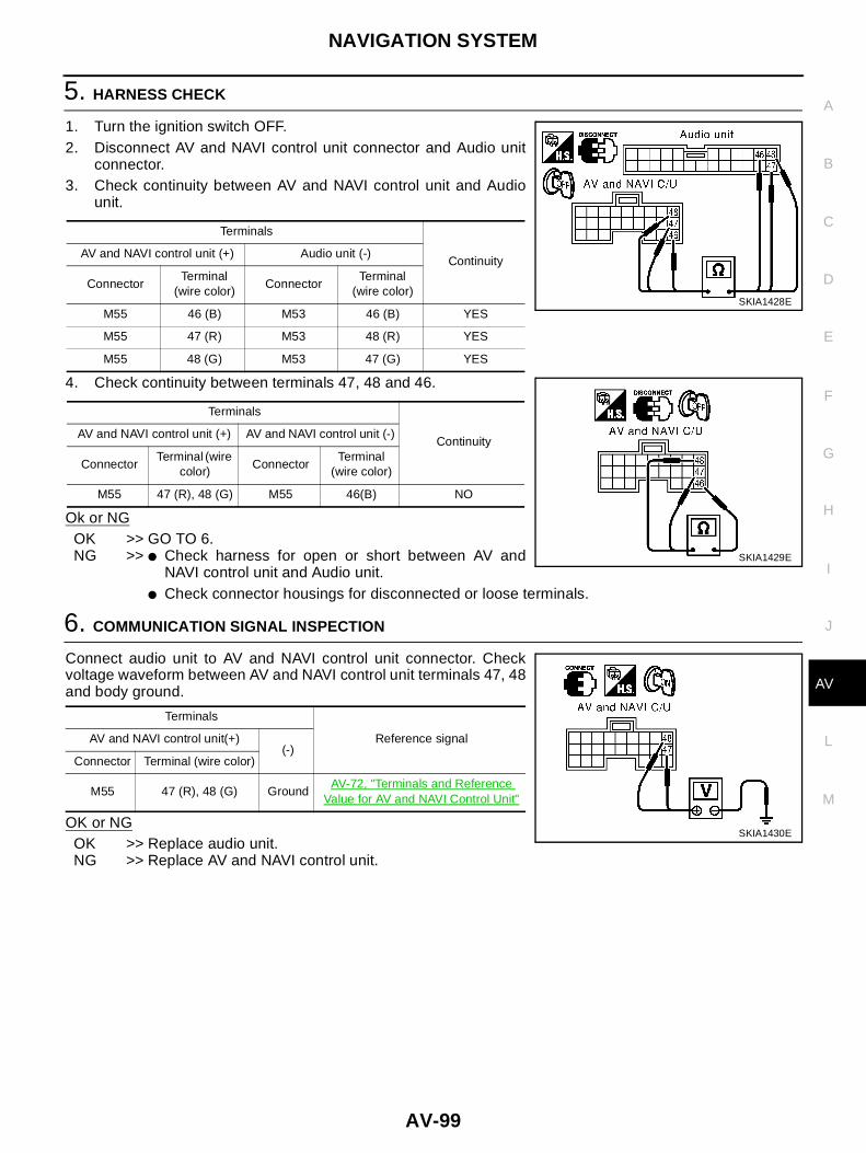
NAVIGATION SYSTEM
AV-99
C
D
E
F
G
H
I
J
L
M
A
B
AV
5. HARNESS CHECK
1. Turn the ignition switch OFF.2. Disconnect AV and NAVI control unit connector and Audio unit
connector.3. Check continuity between AV and NAVI control unit and Audio
unit.
4. Check continuity between terminals 47, 48 and 46.
Ok or NGOK >> GO TO 6.NG >> ● Check harness for open or short between AV and
NAVI control unit and Audio unit.● Check connector housings for disconnected or loose terminals.
6. COMMUNICATION SIGNAL INSPECTION
Connect audio unit to AV and NAVI control unit connector. Checkvoltage waveform between AV and NAVI control unit terminals 47, 48and body ground.
OK or NGOK >> Replace audio unit.NG >> Replace AV and NAVI control unit.
Terminals
ContinuityAV and NAVI control unit (+) Audio unit (-)
ConnectorTerminal
(wire color)Connector
Terminal(wire color)
M55 46 (B) M53 46 (B) YES
M55 47 (R) M53 48 (R) YES
M55 48 (G) M53 47 (G) YES
Terminals
ContinuityAV and NAVI control unit (+) AV and NAVI control unit (-)
ConnectorTerminal (wire
color)Connector
Terminal(wire color)
M55 47 (R), 48 (G) M55 46(B) NO
SKIA1428E
SKIA1429E
Terminals
Reference signalAV and NAVI control unit(+)(-)
Connector Terminal (wire color)
M55 47 (R), 48 (G) GroundAV-72, "Terminals and Reference
Value for AV and NAVI Control Unit"
SKIA1430E

AV-100
NAVIGATION SYSTEM
Air Conditioning Controls (Only) Are Ineffective (Rear Defogger ControlExcluded). EKS0042O
1. HARNESS CHECK
1. Turn the ignition switch OFF.2. Disconnect A/C AUTO AMP. connector and AV and NAVI control unit connector.3. Check continuity between A/C AUTO AMP. and AV and NAVI control unit.
4. Check continuity between AV and NAVI control unit and ground.
Ok or NGOK >> GO TO 2.NG >> ● Check harness between A/C AUTO AMP. and AV and NAVI control unit.
● Check connector housings for disconnected or loose terminals.
2. A/C–AV, AV–AC, AC–CLK COMMUNICATION SIGNAL CHECK
1. Connect A/C AUTO AMP. connector.2. Turn the ignition switch ON.3. Check voltage between AV and NAVI control unit and ground.
OK or NGOK >> GO TO 3.NG >> Replace A/C AUTO AMP.
Terminals
ContinuityAV and NAVI control unit (+) A/C AUTO AMP. (-)
ConnectorTerminal
(wire color)Connector
Terminal(wire color)
M55 43 (L/R) M75 10 (L/R) YES
M55 44 (L/W) M75 9 (L/W) YES
M55 45 (L) M75 20 (L) YES
Terminals
ContinuityAV and NAVI control unit(+)(-)
Connector Terminal (wire color)
M55 43(L/R), 44 (L/W), 45 (L) Ground NO
SKIA1431E
Terminals
Voltage (V)(+)(-)
Connector Terminal (wire color)
M55 43(L/R), 44(L/W), 45 (L) ground Approx. 3.5 or more
SKIA1432E

NAVIGATION SYSTEM
AV-101
C
D
E
F
G
H
I
J
L
M
A
B
AV
3. A/C - AV, AV– AC, AC - CLK COMMUNICATION SIGNAL CHECK
1. Connect AV and NAVI control unit connector.2. Turn the ignition switch ON.3. Check voltage between AV and NAVI control unit terminals 43,
44, 45 and ground.
OK or NGOK >> Replace A/C auto amplifier.NG >> Replace AV and NAVI control unit.
Rear Defogger Does Not Operate EKS0043P
1. HARNESS INSPECTION
1. Turn the ignition switch OFF.2. Disconnect Multifunction switch connector and smart entrance control unit connector.3. Check continuity between Multifunction switch and smart entrance control unit.
4. Check continuity between Multifunction switch and body ground.
OK or NGOK >> GO TO 2.NG >> Open or short in harness between Multifunction switch and smart entrance control unit.
2. CHECK REAR DEFOGGER ON SIGNAL.
1. Connect Multifunction switch connector and smart entrance control unit connector.2. Turn the ignition switch ON.3. Check continuity between Multifunction switch and body ground
when rear defogger switch is operated.
OK or NGOK >> Replace smart entrance control unit.NG >> Replace Multifunction switch.
Terminals
Reference signal(+)(-)
Connector Terminal (wire color)
M55 43(L/R), 44(L/W), 45 (L) groundAV-72, "Terminals and Ref-
erence Value for AV andNAVI Control Unit"
SKIA1432E
Terminals
ContinuityMultifunction switch Smart entrance control unit
ConnectorTerminal
(wire color)Connector
Terminal(wire color)
M49 9 (G/B) M41 22 (G/B) YES
Terminals
ContinuityMultifunction switch(-)
Connector Terminal (wire color)
M49 9 (G/B) Ground NO
SKIA1434E
TerminalsContinuity
Multifunction switch(-)
Connector Terminal (wire color) Press switch. Release switch.
M49 9 (G/B) Ground YES NO
SKIA1435E
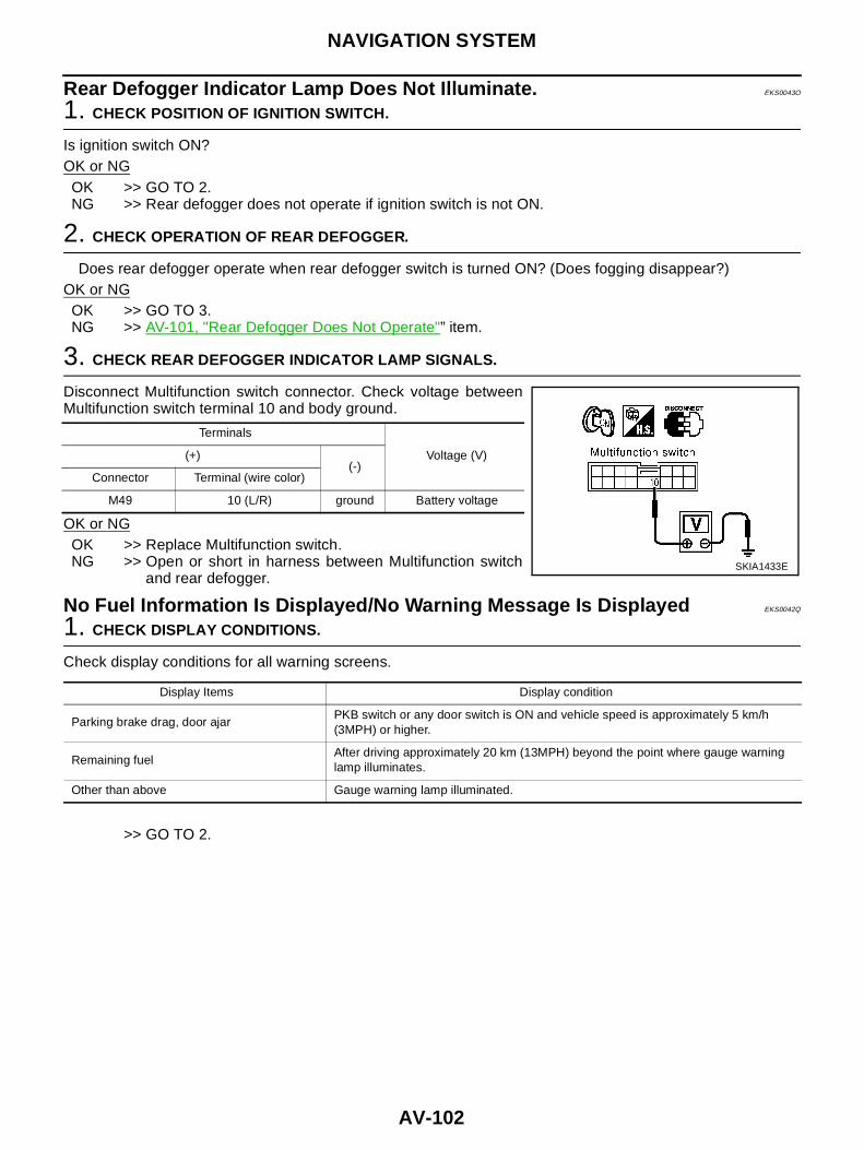
AV-102
NAVIGATION SYSTEM
Rear Defogger Indicator Lamp Does Not Illuminate. EKS0043O
1. CHECK POSITION OF IGNITION SWITCH.
Is ignition switch ON?OK or NG
OK >> GO TO 2.NG >> Rear defogger does not operate if ignition switch is not ON.
2. CHECK OPERATION OF REAR DEFOGGER.
Does rear defogger operate when rear defogger switch is turned ON? (Does fogging disappear?)OK or NG
OK >> GO TO 3.NG >> AV-101, "Rear Defogger Does Not Operate"” item.
3. CHECK REAR DEFOGGER INDICATOR LAMP SIGNALS.
Disconnect Multifunction switch connector. Check voltage betweenMultifunction switch terminal 10 and body ground.
OK or NGOK >> Replace Multifunction switch.NG >> Open or short in harness between Multifunction switch
and rear defogger.
No Fuel Information Is Displayed/No Warning Message Is Displayed EKS0042Q
1. CHECK DISPLAY CONDITIONS.
Check display conditions for all warning screens.
>> GO TO 2.
Terminals
Voltage (V)(+)(-)
Connector Terminal (wire color)
M49 10 (L/R) ground Battery voltage
SKIA1433E
Display Items Display condition
Parking brake drag, door ajarPKB switch or any door switch is ON and vehicle speed is approximately 5 km/h(3MPH) or higher.
Remaining fuelAfter driving approximately 20 km (13MPH) beyond the point where gauge warninglamp illuminates.
Other than above Gauge warning lamp illuminated.

NAVIGATION SYSTEM
AV-103
C
D
E
F
G
H
I
J
L
M
A
B
AV
2. HARNESS CHECK
1. Turn the ignition switch OFF.2. Disconnect connectors of combination meter and AV and NAVI control unit.3. Check continuity between AV and NAVI control unit and combination meter.
4. Check continuity between AV and NAVI control unit and ground.
OK or NGOK >> GO TO 3.NG >> ● Check harness for open or short between AV and NAVI control unit and combination meter for
open or short circuit.● Check connector housings for disconnected or loose terminals.
3. COMMUNICATION SIGNAL (AV–ME) CHECK
1. Connect connectors of combination meter and AV and NAVI control unit.2. Turn the ignition switch ON.3. Check voltage between AV and NAVI control unit terminal 34 and ground.
OK or NGOK >> GO TO 4.NG >> Replace AV and NAVI control unit.
Terminals
ContinuityAV and NAVI control unit (+) Combination meter (-)
Connector Terminal (wire color) Connector Terminal (wire color)
M55 34 (R) M37LHD 41 (R)
YESRHD 27(R)
M55 35 (G) M37LHD 40 (G)
YESRHD 28(G)
Terminals
ContinuityAV and NAVI control unit(+)(-)
Connector Terminal (wire color)
M55 34 (R), 35 (G) Ground NO
SKIA1436E
Terminals
Voltage (V)(+)(-)
Connector Terminal (wire color)
M55 34 (R) groundAV-72, "Terminals and Refer-ence Value for AV and NAVI
Control Unit"
SKIA1437E

AV-104
NAVIGATION SYSTEM
4. COMMUNICATION SIGNAL (ME–AV) CHECK
1. Turn ignition switch to ON and display “VEHICLE ELECTRONIC SYSTEMS” screen.2. Check voltage between AV and NAVI control unit terminal 35
and ground.
OK or NGOK >> Replace AV and NAVI control unit.NG >> Check combination meter system. DI-29, "Inspection/Vehicle Speed Signal" for LHD models or
DI-58, "Inspection/Vehicle Speed Signal" for RHD models.
Previous Conditions Are Not Stored. EKS0042S
1. BATTERY POWER CHECK
● Check AV and NAVI control unit battery power.Refer to AV-87, "Power Supply and Ground Circuit Check" .
OK or NGOK >> Replace AV and NAVI control unit.NG >> Check AV and NAVI control unit battery power system harness.
The Position of The Current-Location Mark Is Not Correct. EKS0042T
1. SELF-DIAGNOSIS
● “Self-diagnosis mode” of the self-diagnosis function AV-78, "Self-Diagnosis Mode" .OK or NG
OK >> GO TO 2.NG >> Check the applicable parts.
2. HISTORY OF ERRORS DIAGNOSIS
● Was any error stored in AV-84, "HISTORY OF ERRORS" of the CONFIRMATION/ADJUSTMENT mode?YES or NO
YES >> AV-84, "DIAGNOSIS BY HISTORY OF ERRORS".NO >> AV-107, "Driving Test".
Radio Wave From The GPS Satellite Is Not Received. EKS0042U
1. ENVIRONMENT CHECK
● Check if any metal object that intercepts radio waves or an object that emits radio waves (such as a porta-ble phone) is located near the GPS antenna. Check if the vehicle is shielded by a building.
OK or NGOK >> ● System is normal.
The GPS antenna may not be able to receive radio waves from the GPS satellite if it is shieldedby metal object or an object emitting radio waves is placed near it.
NG >> GO TO 2.
Terminals
Voltage (V)(+)(-)
Connector Terminal (wire color)
M55 35 (G) groundAV-72, "Terminals and Refer-ence Value for AV and NAVI
Control Unit"
SKIA1438E

NAVIGATION SYSTEM
AV-105
C
D
E
F
G
H
I
J
L
M
A
B
AV
2. SELF-DIAGNOSIS
● Refer to AV-78, "Self-Diagnosis Mode" .OK or NG
OK >> Replace GPS antenna.NG >> Check the applicable parts.
Display Does Not Change When Screen Adjustment Is Performed. EKS0044O
1. CHECK SYMPTOM
Do other systems operate properly?
Do operate.>>Replace the display unit.Do not operate.>>Check the problem again.
Day/Night Display Switching Is Not Done. Night Illumination for AV and NAVIControl Unit Does Not Illuminate. EKS0044P
1. VEHICLE SIGNAL CHECK
1. Start the engine.2. Diagnose the following items with AV-82, "VEHICLE SIGNALS" in CONFIRMATION/ADJUSTMENT
mode.
OK or NGOK >> Replace AV and NAVI control unit.NG >> AV-90, "Illumination Control Signal Check".
On Multifunction switch, a Specific Switch Does Not Operate in All Conditions.EKS0044Q
● Replace Multifunction switch.
Driving Information Is Inaccurate. Maintenance Information Is Inaccurate. EKS0044R
1. VEHICLE SPEED SIGNAL INSPECTION
Check vehicle speed signal. AV-89, "Vehicle Speed Signal Check" .OK or NG
OK >> Replace AV and NAVI control unit.NG >> Check combination meter system. DI-29, "Inspection/Vehicle Speed Signal" for LHD models or
DI-58, "Inspection/Vehicle Speed Signal" for RHD models.
System Does Not Start. EKS0044V
1. INSPECT POWER SYSTEM.
Inspect power system of AV and NAVI control unit. AV-87, "Power Supply and Ground Circuit Check" .OK or NG
OK >> Replace AV and NAVI control unit.NG >> Malfunction in power system of AV and NAVI control unit
<Lamp signals>
Lighting switch position 1 : ON
Lighting switch OFF : OFF

AV-106
NAVIGATION SYSTEM
The Current Position Mark Is in the Wrong Place. EKS0044W
1. CHECK SYMPTOM
● AV-108, "Example of Symptoms Judged Not Abnormal"?”YES or NO
YES >> The limit of the navigation location detection capability has been reached.NO >> GO TO 2.
2. SELF-DIAGNOSIS
● Perform AV-78, "Self-Diagnosis Mode" .OK or NG
OK >> GO TO 3.NG >> Check the applicable parts.
3. ERROR RECORD DIAGNOSIS
● Is there an error listed in AV-84, "HISTORY OF ERRORS" in “CONFIRMATION/ADJUSTMENT” mode?YES or NO
YES >> AV-84, "DIAGNOSIS BY HISTORY OF ERRORS".NO >> GO TO 4.
4. VEHICLE SIGNAL DIAGNOSIS
● Start the engine.● Diagnose the following items with AV-82, "VEHICLE SIGNALS" in “CONFIRMATION/ADJUSTMENT”
mode.
OK or NGOK >> Replace AV and NAVI control unit.NG >> ● If vehicle speed is NG, proceed to AV-89, "Vehicle Speed Signal Check" .
● If reverse is NG, proceed to AV-91, "Reverse Signal Check" .
<Vehicle speed signal>
Vehicle running : ON
While the vehicle is stopped : OFF
<Reverse signal>
Selector lever in R-position : ON
Selector lever in other than R-position : OFF

NAVIGATION SYSTEM
AV-107
C
D
E
F
G
H
I
J
L
M
A
B
AV
The Current-Location Mark Will Not Move Forward/Backward. EKS0044X
1. VEHICLE SIGNAL DIAGNOSIS
● Start the engine.● Diagnose the following items with AV-82, "VEHICLE SIGNALS" in “CONFIRMATION/ADJUSTMENT”
mode.
OK or NGOK >> Replace AV and NAVI control unit.NG >> ● If vehicle speed is NG, proceed to AV-89, "Vehicle Speed Signal Check" .
● If reverse is NG, proceed to AV-91, "Reverse Signal Check" .
The Position of the Current-Location Mark Is Not Correct. EKS004JM
Inspection procedure
1. SELF-DIAGNOSIS
● AV-78, "Operation Procedure" in “Self-Diagnosis Mode.”OK or NG
OK >> GO TO 2.NG >> Check the applicable parts.
2. ERROR RECORD DIAGNOSIS
● Is there an error listed in AV-84, "HISTORY OF ERRORS" in “CONFIRMATION/ADJUSTMENT” mode?Is there an error history?
Yes >> AV-84, "DIAGNOSIS BY HISTORY OF ERRORS".No >> AV-107, "Driving Test"
Driving Test EKS0042V
1. DRIVING TEST 1
1. Scroll the map screen to display the area to make correction. Press “ENTER” and select “CURRENTLOCATION CORRECTION”.
2. Correct direction of the vehicle mark.3. Perform the distance correction of the CONFIRMATION/ADJUSTMENT mode.
NOTE:Normally, adjustment is not necessary because this system has automatic distance correction function.However, when a tire chain is fitted, adjustment in accordance with the tire diameter ratio must be made.
4. Are symptoms applicable to the AV-108, "Example of Symptoms Judged Not Abnormal" present afterdriving the vehicle?
YES or NOYES >> Limit of the location detection capacity of the navigation systemNO >> GO TO 2.
<Vehicle speed signal>
Vehicle running : ON
While the vehicle is stopped : OFF
<Reverse signal>
Selector lever in R-position : ON
Selector lever in other than R-position : OFF

AV-108
NAVIGATION SYSTEM
2. DRIVING TEST 2
● Did any problem occur when the proper test in the following test patterns is performed?● Test pattern
Driving test finds the difference between the symptoms monitored with and without each sensor.– Test pattern 1: Test method with no GPS location correction
Disconnect the GPS antenna connector connected to the AV and NAVI control unit. Accurately adjust thecurrent position and the direction, then drive the vehicle.
– Test pattern 2: Test method with no map-matchingAccurately adjust the current position and the direction. Eject the map DVD-ROM from the AV and NAVIcontrol unit with the ignition switch turned to OFF, then drive the vehicle. After driving, insert the mapDVD-ROM back in the unit, display the track of the vehicle on the map screen and compare it with theactual road configuration.
● Sample tests– <To determine if the current-location mark skips at the same position, if so, whether it is caused by map-
matching or by GPS>Perform test pattern 1.
– <To determine if the pattern of streets displayed is correct or not>Perform test pattern 1 & 2.Compare the track of the vehicle on the map screen and the actual road configuration. For fairly accuratetracking, plotting shall be made every several hundred meters.
– <When the distance is adjusted accurately>Perform test pattern 1 & 2.Drive on a road of which distance is accurately known (by utilizing distance posts on a highway). Calculatethe rate of change (increased/decreased) of the distance by comparing with the actual distance.Correction = A/BA: Distance shown on the screenB: Actual distance
YES or NOYES >> ● If adjustment is insufficient, perform adjustment again.
● If any error is found in the map, please let us know.● Replace AV and NAVI control unit
NO >> Limit of the location detection capacity of the navigation system
Example of Symptoms Judged Not Abnormal EKS0042W
BASIC OPERATIONSymptom Cause Remedy
No image is shown. Display brightness adjustment is set fully toDARK side.
Adjust the display brightness.
No guide sound is heard.Audio guide volume is too low ortoo high.
Volume control is set to OFF, MIN or MAX. Adjust the audio guide volume.
Audio guidance is not available while the vehicleis driving on a dark pink route.
System is not malfunction.
Screen is too dark.Motion of the image is too slow.
Temperature inside the vehicle is low. Wait until the temperature inside the vehiclereaches the proper temperature.
Small black or bright spots appearon the screen.
Symptom peculiar to a liquid crystal display. System is not malfunction.
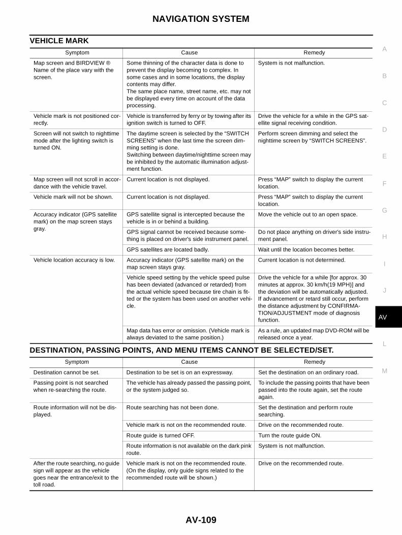
NAVIGATION SYSTEM
AV-109
C
D
E
F
G
H
I
J
L
M
A
B
AV
VEHICLE MARK
DESTINATION, PASSING POINTS, AND MENU ITEMS CANNOT BE SELECTED/SET.
Symptom Cause Remedy
Map screen and BIRDVIEW ®Name of the place vary with thescreen.
Some thinning of the character data is done toprevent the display becoming to complex. Insome cases and in some locations, the displaycontents may differ.The same place name, street name, etc. may notbe displayed every time on account of the dataprocessing.
System is not malfunction.
Vehicle mark is not positioned cor-rectly.
Vehicle is transferred by ferry or by towing after itsignition switch is turned to OFF.
Drive the vehicle for a while in the GPS sat-ellite signal receiving condition.
Screen will not switch to nighttimemode after the lighting switch isturned ON.
The daytime screen is selected by the “SWITCHSCREENS” when the last time the screen dim-ming setting is done.Switching between daytime/nighttime screen maybe inhibited by the automatic illumination adjust-ment function.
Perform screen dimming and select thenighttime screen by “SWITCH SCREENS”.
Map screen will not scroll in accor-dance with the vehicle travel.
Current location is not displayed. Press “MAP” switch to display the currentlocation.
Vehicle mark will not be shown. Current location is not displayed. Press “MAP” switch to display the currentlocation.
Accuracy indicator (GPS satellitemark) on the map screen staysgray.
GPS satellite signal is intercepted because thevehicle is in or behind a building.
Move the vehicle out to an open space.
GPS signal cannot be received because some-thing is placed on driver's side instrument panel.
Do not place anything on driver's side instru-ment panel.
GPS satellites are located badly. Wait until the location becomes better.
Vehicle location accuracy is low. Accuracy indicator (GPS satellite mark) on themap screen stays gray.
Current location is not determined.
Vehicle speed setting by the vehicle speed pulsehas been deviated (advanced or retarded) fromthe actual vehicle speed because tire chain is fit-ted or the system has been used on another vehi-cle.
Drive the vehicle for a while [for approx. 30minutes at approx. 30 km/h(19 MPH)] andthe deviation will be automatically adjusted.If advancement or retard still occur, performthe distance adjustment by CONFIRMA-TION/ADJUSTMENT mode of diagnosisfunction.
Map data has error or omission. (Vehicle mark isalways deviated to the same position.)
As a rule, an updated map DVD-ROM will bereleased once a year.
Symptom Cause Remedy
Destination cannot be set. Destination to be set is on an expressway. Set the destination on an ordinary road.
Passing point is not searchedwhen re-searching the route.
The vehicle has already passed the passing point,or the system judged so.
To include the passing points that have beenpassed into the route again, set the routeagain.
Route information will not be dis-played.
Route searching has not been done. Set the destination and perform routesearching.
Vehicle mark is not on the recommended route. Drive on the recommended route.
Route guide is turned OFF. Turn the route guide ON.
Route information is not available on the dark pinkroute.
System is not malfunction.
After the route searching, no guidesign will appear as the vehiclegoes near the entrance/exit to thetoll road.
Vehicle mark is not on the recommended route.(On the display, only guide signs related to therecommended route will be shown.)
Drive on the recommended route.

AV-110
NAVIGATION SYSTEM
VOICE GUIDE
ROUTE SEARCHING
Automatic route searching is notpossible.
Vehicle is driving on a highway (gray route), or norecommended route is available.
Drive on a road to be searched. Or re-search the route manually. In this case, how-ever, the whole route will be searched.
Performed automatic detoursearch (or detour search). How-ever, the result is the same as thatof the previous search.
Performed search with every conditions consid-ered. However, the result is the same as that ofthe previous search.
System is not malfunction.
Passing points cannot be set. More than five passing points were set. Passing points can be set up to five. To stopat more than five points, perform sharing inseveral steps.
When setting the route, the start-ing point cannot be selected.
The current vehicle location is always set as thestarting point of a route.
System is not malfunction.
Some menu items cannot beselected.
The vehicle is being driven. Stop the vehicle at a safe place and thenoperate the system.
Symptom Cause Remedy
Symptom Cause Remedy
Voice guide will not operate. Note: Voice guide is only available at intersectionsthat satisfy certain conditions (indicated by ● onthe map). Therefore, guidance may not be giveneven when the route on the map changes direc-tion.
System is not malfunction.
The vehicle is not on the recommended route. Return to the recommended route or re-search the route.
Voice guide is turned OFF. Turn the voice guide ON.
Route guide is turned OFF. Turn the route guide ON.
Voice guide does not match theactual road pattern.
Voice guide may vary with the direction to whichthe vehicle is turn and the connection of the roadto other roads.
Drive in conformity to the actual traffic rules.
Symptom Cause Remedy
No route is shown. No road to be searched is found around the des-tination.
Find wider road (orange road or wider)nearby and reset the destination and passingpoints onto it. Take care of the travelingdirection when there are separate up anddown roads.
Starting point and the destination are too close. Set the destination at more distant point.
Conditional traffic regulation (day of the week/time of the day) is set at the area around the cur-rent position or the destination.
Turn the time-regulating search conditionsOFF. Turn “Avoid regulation time” in thesearch conditions OFF.
Indicated route is intermittent. In some areas, highways (gray routes) are not
used for the search Therefore, the route to thecurrent position or the passing points may beintermittent.
System is not malfunction.
When the vehicle has passed therecommended route, it is deletedfrom the screen.
A recommended route is controlled by each sec-tion. When the vehicle has passed the passingpoint 1, then the map data from the starting pointup to the passing point 1 will be deleted. (Thedata may remain undeleted in some area.)
System is not malfunction.

NAVIGATION SYSTEM
AV-111
C
D
E
F
G
H
I
J
L
M
A
B
AV
EXAMPLES OF CURRENT-LOCATION MARK DISPLACEMENTVehicle's travel amount is calculated by reading its travel distance and turning angle. Therefore, if the vehicle
is driven in the following manner, an error will occur in the vehicle's current location display. If correct locationhas not been restored after driving the vehicle for a while, perform location correction.
Detouring route is recommended. In some areas, highways (gray routes) are notused for the search. Therefore, detour route maybe recommended.
Set the route closer to the basic route (grayroute).
A detour route may be shown when some trafficregulation (one-way traffic, etc.) is set at the areaaround the starting point or the destination.
Slightly move the starting point or the desti-nation, or set the passing point on the routeof your choice.
In the area where highways (gray routes) areused for the search, left turn has priority aroundthe current position and the destination (passingpoints). For this reason, the recommended routemay be detouring.
System is not malfunction.
Landmarks on the map do notmatch the actual ones.
This can happen due to omission or error in themap data.
As a rule, an updated map DVD-ROM will bereleased once a year. Wait until the latestmap has become available.
Recommended route is far fromthe starting point, passing points,and destination.
Starting point, passing points, and destination ofthe route guide were set far from the desiredpoints because route searching data aroundthese area were not stored.
Reset the destination onto the road nearby. Ifthis road is one of the highways (grayroutes), an ordinary road nearby may be dis-played as the recommended route.
Symptom Cause Remedy
SEL698V

AV-112
NAVIGATION SYSTEM
Cause (condition) -:While driving ooo:Display Driving condition Remarks (correction, etc.)
Road config-uration
Y-intersections
At a Y intersection or similar gradualdivision of roads, error the direction oftravel deduced by the sensor may resultin the current-location mark appearingon the wrong road.
If after travelling about 10 km (6miles) the correct location has notbeen restored, perform locationcorrection and, if necessary,direction correction.
Spiral roads
When driving on a large, continuous spi-ral road (such as loop bridge), turningangle error is accumulated and the vehi-cle mark may deviate from the correctlocation.
Straight roadsWhen driving on a long, straight roadand slow curve without stopping, map-matching does not work effectivelyenough and distance errors may accu-mulate. As a result, the vehicle markmay deviate from the correct locationwhen the vehicle turned at a corner.
Zigzag roads
When driving on a zigzag road, the mapmay be matched to other roads in thesimilar direction nearby at every turn,and the vehicle mark may deviate fromthe correct location.
Roads laid out in a grid pattern
When driving at where roads are laid outin a grid pattern, where many roads arerunning in the similar direction nearby,the map may be matched to them bymistake and the vehicle mark may devi-ate from the correct location.
Parallel roads
When two roads are running in parallel(such as highway and sideway), themap may be matched to the other roadby mistake and the vehicle mark maydeviate from the correct location.
ELK0192D
ELK0193D
ELK0194D
ELK0195D
ELK0196D
ELK0197D
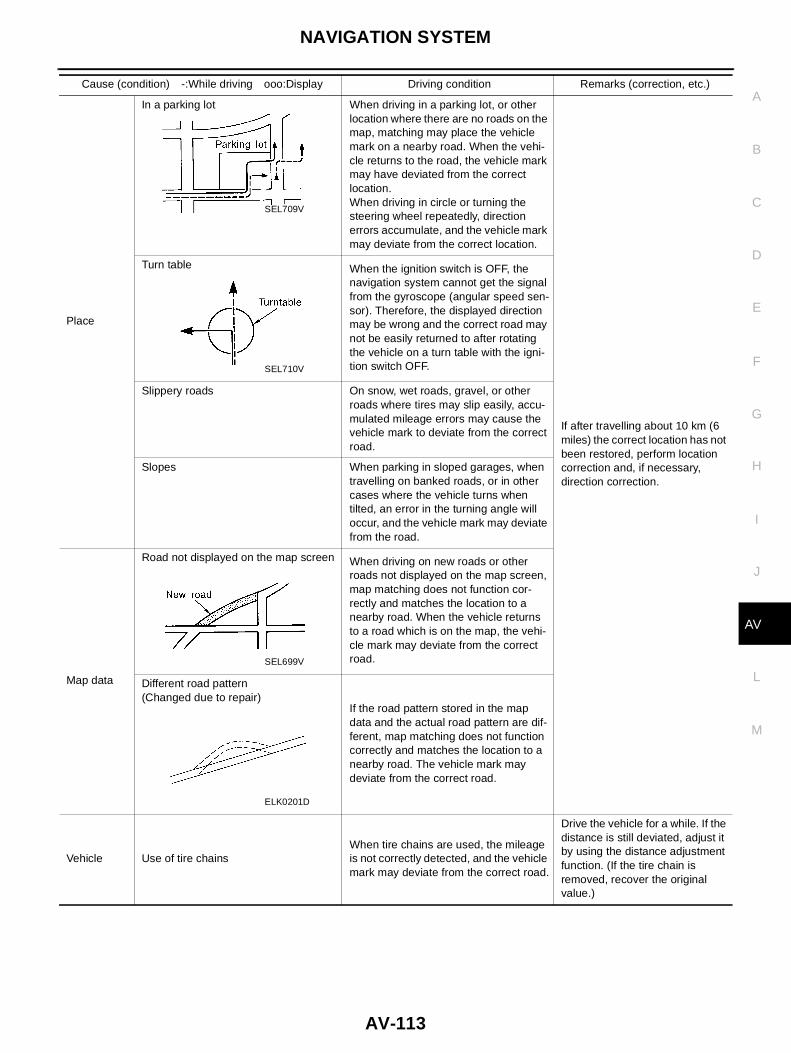
NAVIGATION SYSTEM
AV-113
C
D
E
F
G
H
I
J
L
M
A
B
AV
Place
In a parking lot When driving in a parking lot, or otherlocation where there are no roads on themap, matching may place the vehiclemark on a nearby road. When the vehi-cle returns to the road, the vehicle markmay have deviated from the correctlocation.When driving in circle or turning thesteering wheel repeatedly, directionerrors accumulate, and the vehicle markmay deviate from the correct location.
If after travelling about 10 km (6miles) the correct location has notbeen restored, perform locationcorrection and, if necessary,direction correction.
Turn table When the ignition switch is OFF, thenavigation system cannot get the signalfrom the gyroscope (angular speed sen-sor). Therefore, the displayed directionmay be wrong and the correct road maynot be easily returned to after rotatingthe vehicle on a turn table with the igni-tion switch OFF.
Slippery roads On snow, wet roads, gravel, or otherroads where tires may slip easily, accu-mulated mileage errors may cause thevehicle mark to deviate from the correctroad.
Slopes When parking in sloped garages, whentravelling on banked roads, or in othercases where the vehicle turns whentilted, an error in the turning angle willoccur, and the vehicle mark may deviatefrom the road.
Map data
Road not displayed on the map screen When driving on new roads or otherroads not displayed on the map screen,map matching does not function cor-rectly and matches the location to anearby road. When the vehicle returnsto a road which is on the map, the vehi-cle mark may deviate from the correctroad.
Different road pattern(Changed due to repair)
If the road pattern stored in the mapdata and the actual road pattern are dif-ferent, map matching does not functioncorrectly and matches the location to anearby road. The vehicle mark maydeviate from the correct road.
Vehicle Use of tire chainsWhen tire chains are used, the mileageis not correctly detected, and the vehiclemark may deviate from the correct road.
Drive the vehicle for a while. If thedistance is still deviated, adjust itby using the distance adjustmentfunction. (If the tire chain isremoved, recover the originalvalue.)
Cause (condition) -:While driving ooo:Display Driving condition Remarks (correction, etc.)
SEL709V
SEL710V
SEL699V
ELK0201D
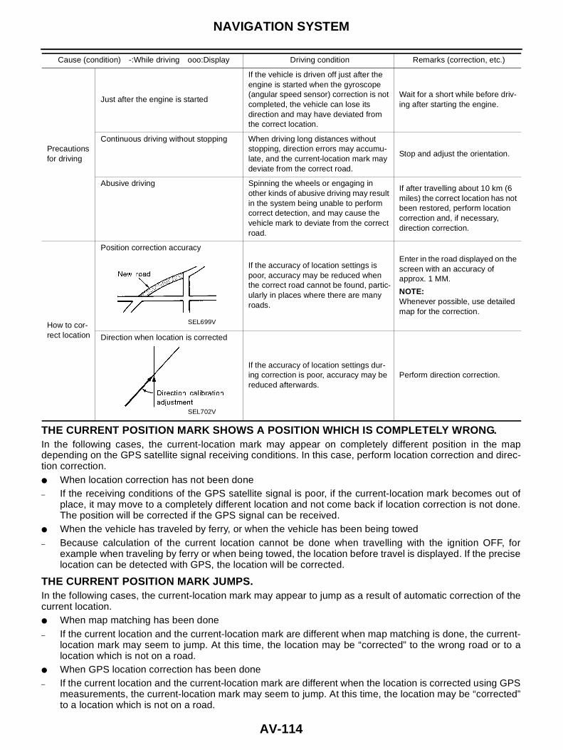
AV-114
NAVIGATION SYSTEM
THE CURRENT POSITION MARK SHOWS A POSITION WHICH IS COMPLETELY WRONG.In the following cases, the current-location mark may appear on completely different position in the mapdepending on the GPS satellite signal receiving conditions. In this case, perform location correction and direc-tion correction.● When location correction has not been done– If the receiving conditions of the GPS satellite signal is poor, if the current-location mark becomes out of
place, it may move to a completely different location and not come back if location correction is not done.The position will be corrected if the GPS signal can be received.
● When the vehicle has traveled by ferry, or when the vehicle has been being towed– Because calculation of the current location cannot be done when travelling with the ignition OFF, for
example when traveling by ferry or when being towed, the location before travel is displayed. If the preciselocation can be detected with GPS, the location will be corrected.
THE CURRENT POSITION MARK JUMPS.In the following cases, the current-location mark may appear to jump as a result of automatic correction of thecurrent location.● When map matching has been done– If the current location and the current-location mark are different when map matching is done, the current-
location mark may seem to jump. At this time, the location may be “corrected” to the wrong road or to alocation which is not on a road.
● When GPS location correction has been done– If the current location and the current-location mark are different when the location is corrected using GPS
measurements, the current-location mark may seem to jump. At this time, the location may be “corrected”to a location which is not on a road.
Precautionsfor driving
Just after the engine is started
If the vehicle is driven off just after theengine is started when the gyroscope(angular speed sensor) correction is notcompleted, the vehicle can lose itsdirection and may have deviated fromthe correct location.
Wait for a short while before driv-ing after starting the engine.
Continuous driving without stopping When driving long distances withoutstopping, direction errors may accumu-late, and the current-location mark maydeviate from the correct road.
Stop and adjust the orientation.
Abusive driving Spinning the wheels or engaging inother kinds of abusive driving may resultin the system being unable to performcorrect detection, and may cause thevehicle mark to deviate from the correctroad.
If after travelling about 10 km (6miles) the correct location has notbeen restored, perform locationcorrection and, if necessary,direction correction.
How to cor-rect location
Position correction accuracy
If the accuracy of location settings ispoor, accuracy may be reduced whenthe correct road cannot be found, partic-ularly in places where there are manyroads.
Enter in the road displayed on thescreen with an accuracy ofapprox. 1 MM.
NOTE:Whenever possible, use detailedmap for the correction.
Direction when location is corrected
If the accuracy of location settings dur-ing correction is poor, accuracy may bereduced afterwards.
Perform direction correction.
Cause (condition) -:While driving ooo:Display Driving condition Remarks (correction, etc.)
SEL699V
SEL702V

NAVIGATION SYSTEM
AV-115
C
D
E
F
G
H
I
J
L
M
A
B
AV
THE CURRENT LOCATION MARK IS IN A RIVER OR THE SEA.The navigation system moves the current location mark with no distinction between land and rivers or sea. Ifthe location mark is somehow out of place, it may appear that the vehicle is driving in a river or the sea.
WHEN DRIVING ON THE SAME ROAD, SOMETIMES THE CURRENT-LOCATION MARK IS INTHE RIGHT PLACE AND SOMETIMES IT IS THE WRONG PLACE.The conditions of the GPS antenna (GPS data) and gyroscope (angular speed sensor) change gradually.Depending on the road traveled and the operation of the steering wheel, the location detection results will bedifferent. Therefore, even on a road on which the location has never been wrong, conditions may cause thevehicle mark to deviate.
LOCATION CORRECTION BY MAP MATCHING IS SLOW.● The map matching function needs to refer to the data of the surrounding area. It is necessary to drive
some distance for the function to work.● Because map matching operates on this principle, when there are many roads running in similar direc-
tions in the surrounding area, no matching determination may be made. The location may not be cor-rected until some special feature is found.
ALTHOUGH THE GPS RECEIVING DISPLAY IS GREEN, THE VEHICLE MARK DOES NOTRETURN TO THE CORRECT LOCATION.● The GPS accuracy has an error of about 10 m (30 ft.). In some cases the current-location mark may not
be on the correct street, even when GPS location-correction is done.● The navigation system compares the results of GPS location detection with the results from map-match-
ing location detection. The one which is determined to have higher accuracy is used.● GPS location correction may not be performed when the vehicle is stopped.
THE NAME OF THE CURRENT PLACE IS NOT DISPLAYED.The current place name may not be displayed if there are no place names displayed on the map screen.
CONTENTS OF THE DISPLAY DIFFER FOR THE BIRDVIEW® AND THE (FLAT) MAP SCREEN.Difference of the BIRDVIEW® Screen From the Flat Map Screen Are as Follows.● The current place name displays names which are primarily in the direction of vehicle travel.● The amount of time before the vehicle travel or turn angle is updated on the screen is longer than for the
(flat) map display.● The conditions for display of place names, roads, and other data are different for nearby areas and for
more distant areas.● Some thinning of the character data is done to prevent the display becoming to complex. In some cases
and in some locations, the display contents may differ.● The same place name, street name, etc. may be displayed multiple times.

AV-116
NAVIGATION SYSTEM
Program Loading EKS0042X
NOTE:Program loading is operated when the version of soft is upgraded to the latest one, or when language isswitched.
Removal and Installation of AV&NAVI Control Unit EKS00445
● AV-42, "Removal and Installation of Audio Unit".
SKIA1439E
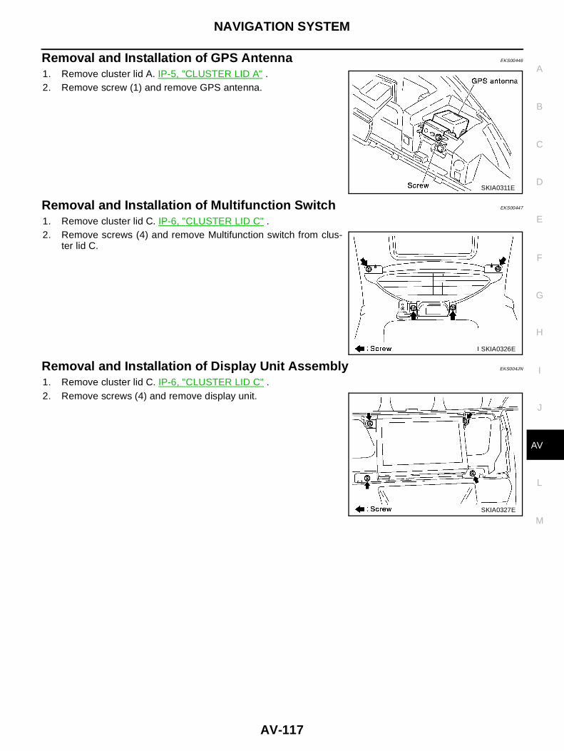
NAVIGATION SYSTEM
AV-117
C
D
E
F
G
H
I
J
L
M
A
B
AV
Removal and Installation of GPS Antenna EKS00446
1. Remove cluster lid A. IP-5, "CLUSTER LID A" .2. Remove screw (1) and remove GPS antenna.
Removal and Installation of Multifunction Switch EKS00447
1. Remove cluster lid C. IP-6, "CLUSTER LID C" .2. Remove screws (4) and remove Multifunction switch from clus-
ter lid C.
Removal and Installation of Display Unit Assembly EKS004JN
1. Remove cluster lid C. IP-6, "CLUSTER LID C" .2. Remove screws (4) and remove display unit.
SKIA0311E
SKIA0326E
SKIA0327E

AV-118
NAVIGATION SYSTEM