
AV300Series(High Performance Butterfly Valve) - AlohanHigh Performance Butterfly Valve... · ASTM...
16
Transcript of AV300Series(High Performance Butterfly Valve) - AlohanHigh Performance Butterfly Valve... · ASTM...
AV300 Series2
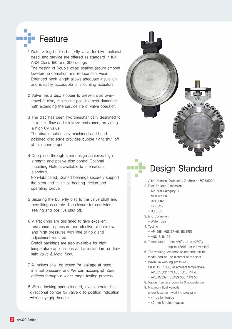
1. Valve Nominal Diameter : 2" (50A) ~ 60" (1500A)
2. Face To face Dimension
- API 609 Category B
- MSS SP-68
- DIN 3202
- ISO 5752
- BS 5155
3. End Connetion
- Wafer, Lug
4. Testing
- API 598, MSS SP-61, BS 6755
- ANSI B 16.104
5. Temperature : from -50℃ up to +260℃
(up to +380℃ for HT version)
6. The working temperature depends on the
media and on the material of the seat
7. Maximum working pressure :
Class 150 / 300, at ambient temperature
- AV.301/302 : CLASS 150 / PN 20
- AV.331/332 : CLASS 300 / PN 50
8. Vacuum service down to 0 absolute bar
9. Maximum fluid velocity,
under Maximum working pressure. :
- 4 m/s for liquids
- 40 m/s for clean gases
Feature
Design Standard
1 Wafer & lug bodies butterfly valve for bi-directionaldead-end service are offered as standard in fullANSI Class 150 and 300 ratings.The design of Double offset sealing assure smoothlow-torque operation and reduce seat wear.Extended neck length allows adequate insulationand is easily accessible for mounting actuators.
2 Valve has a disc stopper to prevent disc over-travel of disc, minimizing possible seat damangewith extending the service life of valve operator.
3 The disc has been hydromechanically designed tomaximize flow and minimize resistance, providinga high Cv value.The disc is spherically machined and handpolished disc edge provides bubble-tight shut-offat minimum torque.
4 One piece through stem design achieves highstrength and posive disc control Optionalmounting Plate is available to internationalstandard.Non-lubricated, Coated bearings securely supportthe stem and minimize bearing friction andoperating torque.
5 Securing the butterfly disc to the valve shaft andpermitting accurate disc closure for consistentsealing and positive shut off.
6 V-Packings are designed to give excellentresistance to pressure and efective at both lowand high pressures with little of no glandadjustment required.Grafoil packings are also available for hightemperature applications and are standard on fire-safe valve & Metal Seat.
7 All valves shall be tested for leakage at ratedinternal pressure, and We can accomplish Zerodefects through a wider range testing process
8 With a locking spring loaded, lever operator hasdirectional pointer for valve disc position indicationwith easy-grip handle
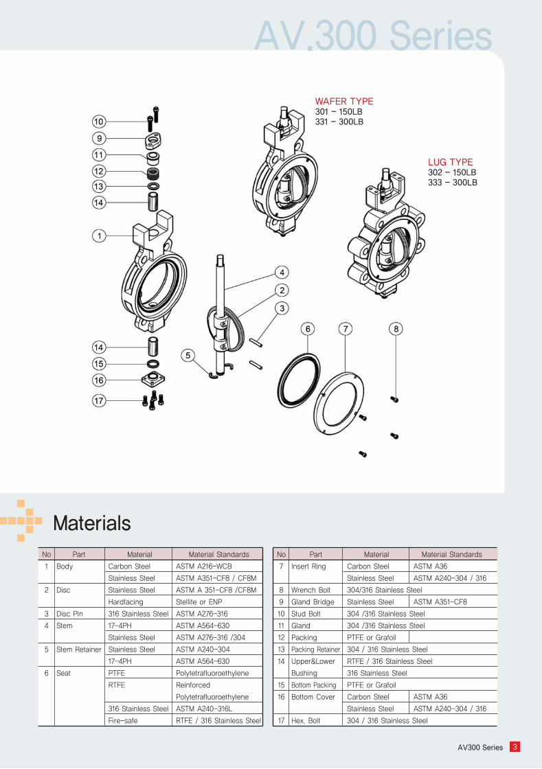
AV.300 Series
AV300 Series 3
No
1
2
3
4
5
6
Part
Body
Disc
Disc Pin
Stem
Stem Retainer
Seat
Material
Carbon Steel
Stainless Steel
Stainless Steel
Hardfacing
316 Stainless Steel
17-4PH
Stainless Steel
Stainless Steel
17-4PH
PTFE
RTFE
316 Stainless Steel
Fire-safe
Material Standards
ASTM A216-WCB
ASTM A351-CF8 / CF8M
ASTM A 351-CF8 /CF8M
Stellite or ENP
ASTM A276-316
ASTM A564-630
ASTM A276-316 /304
ASTM A240-304
ASTM A564-630
Polytetrafluoroethylene
Reinforced
Polytetrafluoroethylene
ASTM A240-316L
RTFE / 316 Stainless Steel
No
7
8
9
10
11
12
13
14
15
16
17
Material
Carbon Steel
Stainless Steel
304/316 Stainless Steel
Stainless Steel
304 /316 Stainless Steel
304 /316 Stainless Steel
PTFE or Grafoil
304 / 316 Stainless Steel
RTFE / 316 Stainless Steel
316 Stainless Steel
PTFE or Grafoil
Carbon Steel
Stainless Steel
304 / 316 Stainless Steel
Material Standards
ASTM A36
ASTM A240-304 / 316
ASTM A351-CF8
ASTM A36
ASTM A240-304 / 316
MaterialsPart
Insert Ring
Wrench Bolt
Gland Bridge
Stud Bolt
Gland
Packing
Packing Retainer
Upper&Lower
Bushing
Bottom Packing
Bottom Cover
Hex. Bolt
WAFER TYPE301 - 150LB331 - 300LB
LUG TYPE302 - 150LB333 - 300LB
AV300 Series4
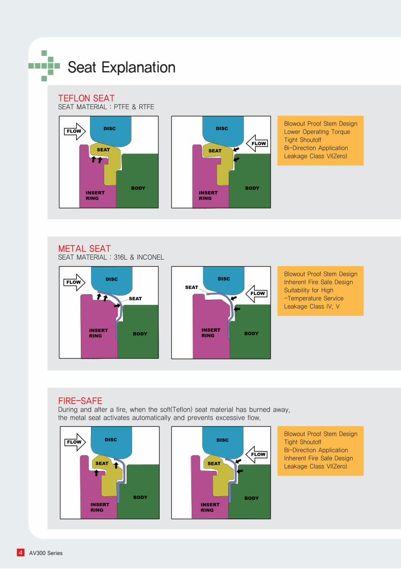
TEFLON SEATSEAT MATERIAL : PTFE & RTFE
FIRE-SAFEDuring and after a fire, when the soft(Teflon) seat material has burned away,the metal seat activates automatically and prevents excessive flow.
METAL SEATSEAT MATERIAL : 316L & INCONEL
Blowout Proof Stem Design Lower Operating TorqueTight ShoutoffBi-Direction ApplicationLeakage Class VI(Zero)
Blowout Proof Stem DesignInherent Fire Safe DesignSuitability for High -Temperature ServiceLeakage Class IV, V
Blowout Proof Stem DesignTight ShoutoffBi-Direction ApplicationInherent Fire Safe DesignLeakage Class VI(Zero)
Seat Explanation
AV.300 Series
AV300 Series 5
Class VI
Class V
Class IV
ANSI
B16.104-1976
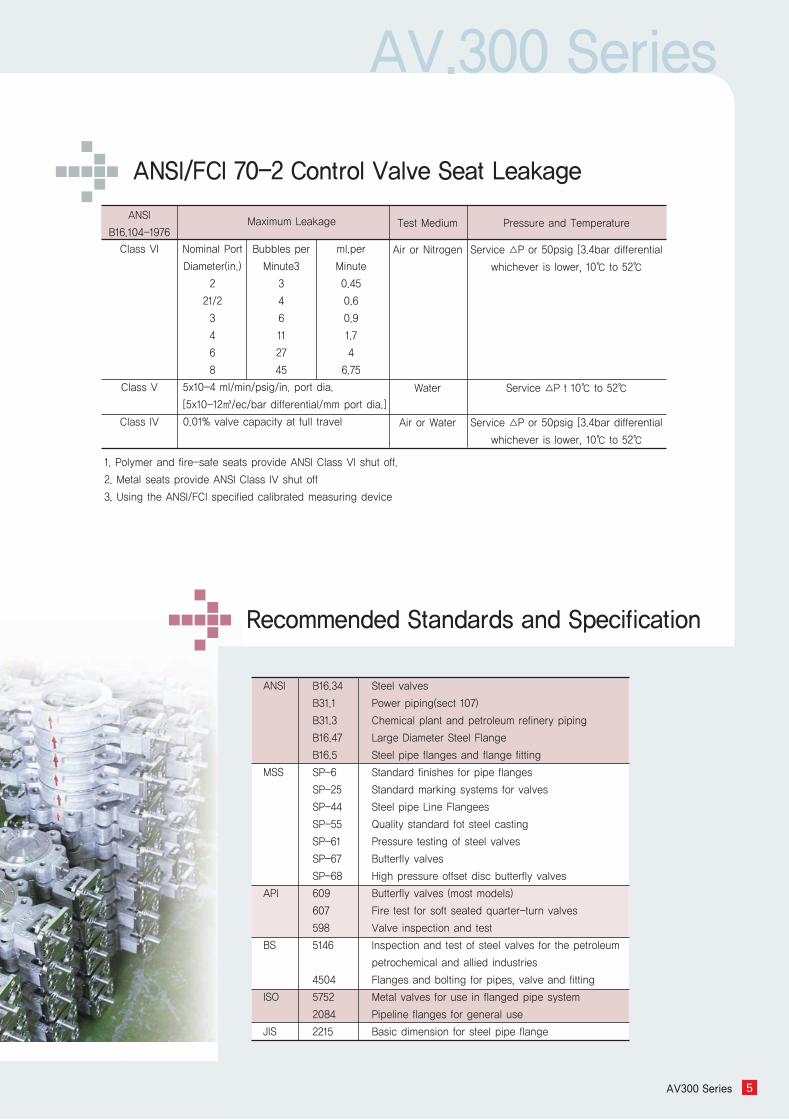
1. Polymer and fire-safe seats provide ANSI Class VI shut off.
2. Metal seats provide ANSI Class IV shut off
3. Using the ANSI/FCI specified calibrated measuring device
Maximum Leakage Test Medium
Air or Nitrogen
Water
Air or Water
Pressure and Temperature
Service △P or 50psig [3.4bar differential
whichever is lower, 10℃ to 52℃
Service △P t 10℃ to 52℃
Service △P or 50psig [3.4bar differential
whichever is lower, 10℃ to 52℃
Nominal Port
Diameter(in.)
2
21/2
3
4
6
8
Bubbles per
Minute3
3
4
6
11
27
45
ml.per
Minute
0.45
0.6
0.9
1.7
4
6.75
5x10⁻⁴ ml/min/psig/in. port dia.
[5x10-12㎥/ec/bar differential/mm port dia.]
0.01% valve capacity at full travel
ANSI
MSS
API
BS
ISO
JIS
B16.34
B31.1
B31.3
B16.47
B16.5
SP-6
SP-25
SP-44
SP-55
SP-61
SP-67
SP-68
609
607
598
5146
4504
5752
2084
2215
Steel valves
Power piping(sect 107)
Chemical plant and petroleum refinery piping
Large Diameter Steel Flange
Steel pipe flanges and flange fitting
Standard finishes for pipe flanges
Standard marking systems for valves
Steel pipe Line Flangees
Quality standard fot steel casting
Pressure testing of steel valves
Butterfly valves
High pressure offset disc butterfly valves
Butterfly valves (most models)
Fire test for soft seated quarter-turn valves
Valve inspection and test
Inspection and test of steel valves for the petroleum
petrochemical and allied industries
Flanges and bolting for pipes, valve and fitting
Metal valves for use in flanged pipe system
Pipeline flanges for general use
Basic dimension for steel pipe flange
ANSI/FCI 70-2 Control Valve Seat Leakage
Recommended Standards and Specification
6 AV300 Series
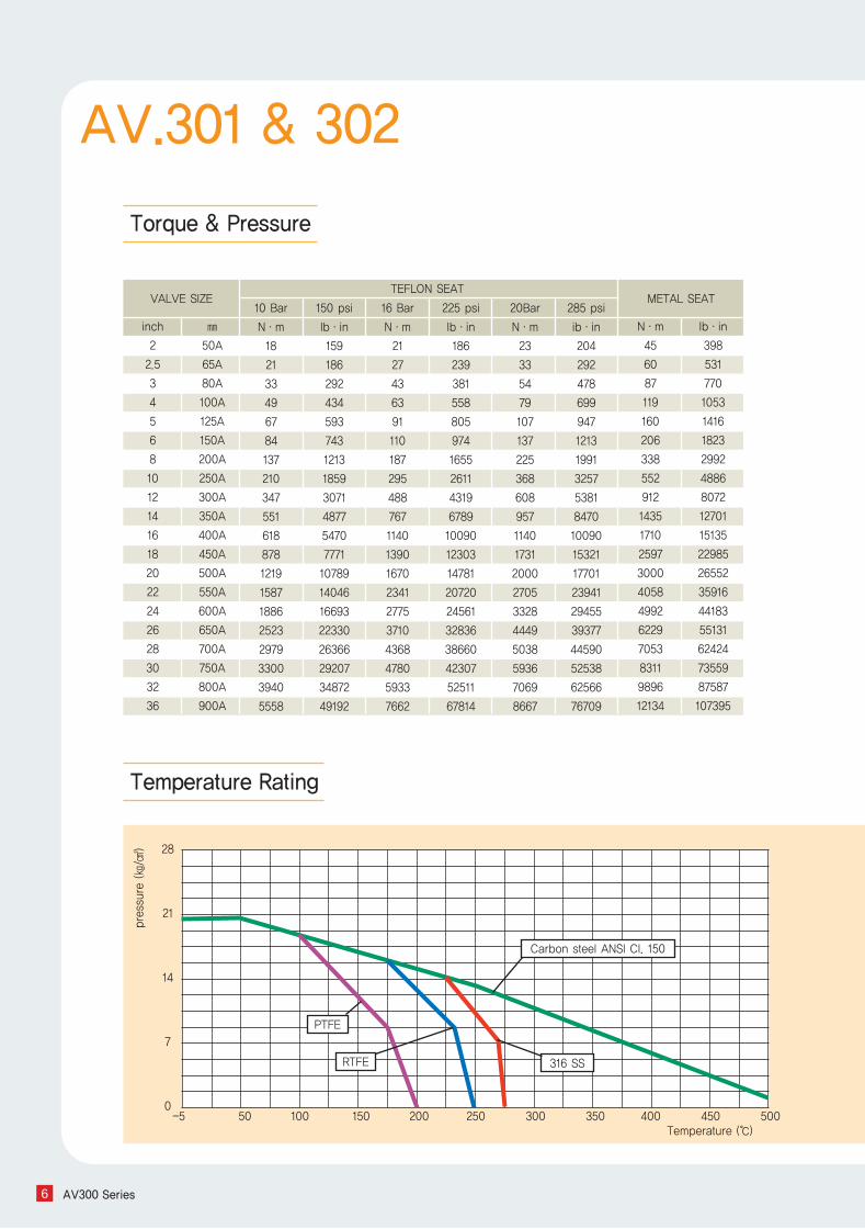
Torque& Pressure
VALVE SIZETEFLON SEAT
METAL SEAT
inch
2
2.5
3
4
5
6
8
10
12
14
16
18
20
22
24
26
28
30
32
36
㎜
50A
65A
80A
100A
125A
150A
200A
250A
300A
350A
400A
450A
500A
550A
600A
650A
700A
750A
800A
900A
N·m
45
60
87
119
160
206
338
552
912
1435
1710
2597
3000
4058
4992
6229
7053
8311
9896
12134
lb·in
398
531
770
1053
1416
1823
2992
4886
8072
12701
15135
22985
26552
35916
44183
55131
62424
73559
87587
107395
10 Bar
N·m
18
21
33
49
67
84
137
210
347
551
618
878
1219
1587
1886
2523
2979
3300
3940
5558
150 psi
lb·in
159
186
292
434
593
743
1213
1859
3071
4877
5470
7771
10789
14046
16693
22330
26366
29207
34872
49192
16 Bar
N·m
21
27
43
63
91
110
187
295
488
767
1140
1390
1670
2341
2775
3710
4368
4780
5933
7662
20Bar
N·m
23
33
54
79
107
137
225
368
608
957
1140
1731
2000
2705
3328
4449
5038
5936
7069
8667
225 psi
lb·in
186
239
381
558
805
974
1655
2611
4319
6789
10090
12303
14781
20720
24561
32836
38660
42307
52511
67814
285 psi
ib·in
204
292
478
699
947
1213
1991
3257
5381
8470
10090
15321
17701
23941
29455
39377
44590
52538
62566
76709
6
Temperature Rating
AV.301 & 302pressure (㎏/㎠) 28
21
14
7
0
Temperature (℃)-5 50 100 150 200 250 300 350 400 450 500
PTFE
RTFE 316 SS
Carbon steel ANSI Cl. 150
AV.300 Series
AV300 Series 7
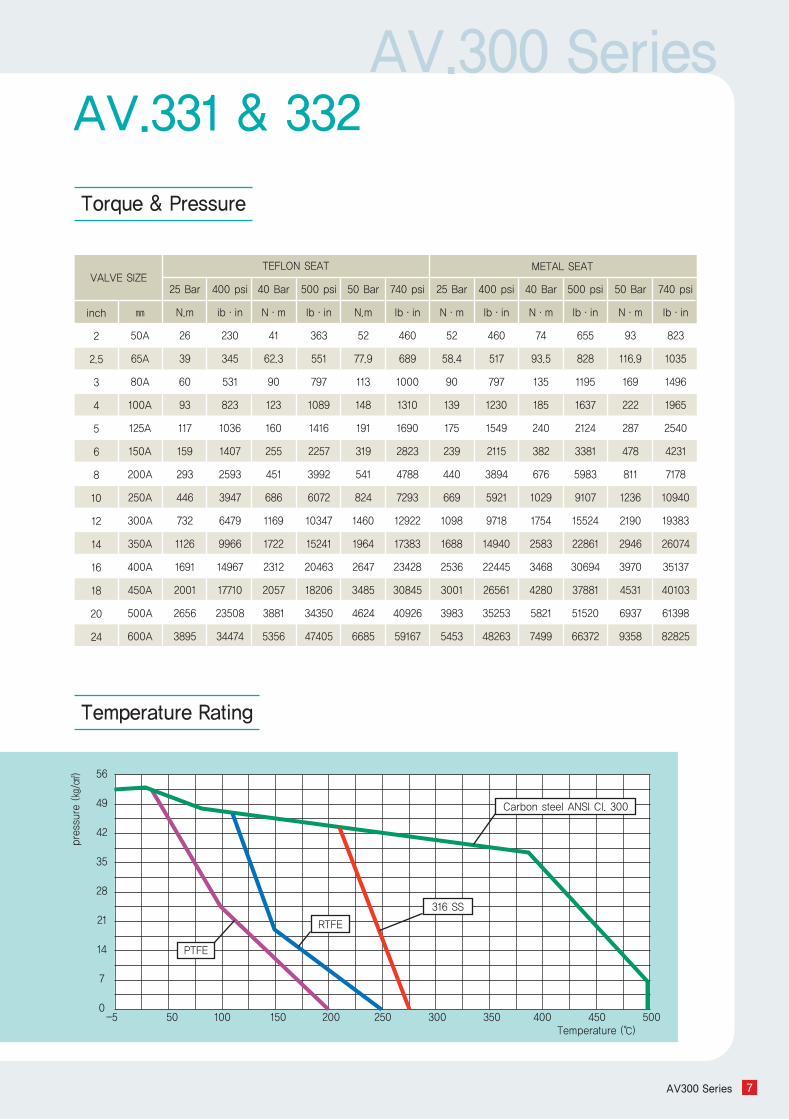
VALVE SIZETEFLON SEAT METAL SEAT
inch
2
2.5
3
4
5
6
8
10
12
14
16
18
20
24
㎜
50A
65A
80A
100A
125A
150A
200A
250A
300A
350A
400A
450A
500A
600A
25 Bar
N.m
26
39
60
93
117
159
293
446
732
1126
1691
2001
2656
3895
400 psi
ib·in
230
345
531
823
1036
1407
2593
3947
6479
9966
14967
17710
23508
34474
40 Bar
N·m
41
62.3
90
123
160
255
451
686
1169
1722
2312
2057
3881
5356
50 Bar
N.m
52
77.9
113
148
191
319
541
824
1460
1964
2647
3485
4624
6685
500 psi
lb·in
363
551
797
1089
1416
2257
3992
6072
10347
15241
20463
18206
34350
47405
740 psi
lb·in
460
689
1000
1310
1690
2823
4788
7293
12922
17383
23428
30845
40926
59167
25 Bar
N·m
52
58.4
90
139
175
239
440
669
1098
1688
2536
3001
3983
5453
400 psi
lb·in
460
517
797
1230
1549
2115
3894
5921
9718
14940
22445
26561
35253
48263
40 Bar
N·m
74
93.5
135
185
240
382
676
1029
1754
2583
3468
4280
5821
7499
500 psi
lb·in
655
828
1195
1637
2124
3381
5983
9107
15524
22861
30694
37881
51520
66372
50 Bar
N·m
93
116.9
169
222
287
478
811
1236
2190
2946
3970
4531
6937
9358
740 psi
lb·in
823
1035
1496
1965
2540
4231
7178
10940
19383
26074
35137
40103
61398
82825
Torque& Pressure
Temperature Rating
AV.331 & 332pressure (㎏/㎠) 56
49
42
35
28
21
14
7
0
Temperature (℃)-5 50 100 150 200 250 300 350 400 450 500
PTFE
RTFE
316 SS
Carbon steel ANSI CI. 300

AV300 Series8
Dimension - “Q1” “Q2” is the dimensionensuring the pipes or flanges are properlyaligned so that the valve disc does notcontact them in any setting Misalignment willresult in damage to the valve.
Applicable Flange Standard - ANSI CL. 150- ISO/DIN PN 10/ 16/ 20- JIS 10K/ 16K/ 20K
All dimensions are approximate, pls contactthe factory for more details.
AV.301 - WAFTER TYPE CL. 150AV.302 - LUG TYPE CL. 150
Dimension
AV.301 & 302
VALVE SIZE AV301 & 302 Dimension
inch
2
2.5
3
4
5
6
8
10
12
14
16
18
20
22
24
26
28
30
32
36
㎜
50A
65A
80A
100A
125A
150A
200A
250A
300A
350A
400A
450A
500A
550A
600A
650A
700A
750A
800A
900A
Q1
Φ32
Φ54
Φ65
Φ86
Φ102
Φ132
Φ181
Φ228
Φ270
Φ310
Φ355
Φ407
Φ457
Φ494
Φ537
Φ582
Φ638
Φ670
Φ740
Φ855
Q2
Φ46
Φ65
Φ76
Φ97
Φ116
Φ144
Φ192
Φ242
Φ285
Φ326
Φ370
Φ425
Φ475
Φ514
Φ558
Φ608
Φ664
Φ714
Φ764
Φ878
ΦA
Φ47
Φ64
Φ75
Φ95
Φ113
Φ140
Φ190
Φ238
Φ280
Φ321
Φ365
Φ419
Φ469
Φ509
Φ553
Φ602
Φ657
Φ710
Φ760
Φ872
ΦB
Φ104
Φ120
Φ130
Φ156
Φ186
Φ213
Φ266
Φ324
Φ372
Φ418
Φ480
Φ536
Φ590
Φ644
Φ694
Φ740
Φ804
Φ860
Φ910
Φ1012
C1
95
115
116
130
148
162
202
232
262
294
346
376
406
465
490
520
549
585
625
675
C3
245
285
291
315
356
384
467
532
592
659
770
830
885
985
1045
1105
1164
1235
1300
1415
C2
150
170
175
185
208
222
265
300
330
365
424
454
479
520
555
585
615
650
675
740
D
44
46
48
54
57
57
64
71
81
92
102
114
127
154
154
165
165
190
190
203
D
C2
C1
C3
ΦB
PreferredDirection
ΦA
Q1
Q2
AV.300 Series
AV300 Series 9
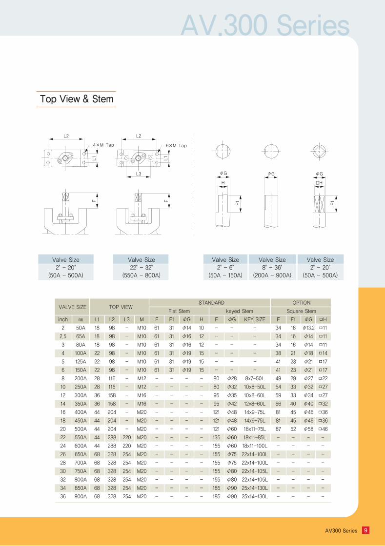
Top View & Stem
VALVE SIZE TOP VIEWSTANDARD OPTION
Flat Stem keyed Stem Square Stem
inch
2
2.5
3
4
5
6
8
10
12
14
16
18
20
22
24
26
28
30
32
34
36
㎜
50A
65A
80A
100A
125A
150A
200A
250A
300A
350A
400A
450A
500A
550A
600A
650A
700A
750A
800A
850A
900A
L1
18
18
18
22
22
22
28
28
36
36
44
44
44
44
44
68
68
68
68
68
68
L2
98
98
98
98
98
98
116
116
158
158
204
204
204
288
288
328
328
328
328
328
328
L3
-
-
-
-
-
-
-
-
-
-
-
-
-
220
220
254
254
254
254
254
254
M
M10
M10
M10
M10
M10
M10
M12
M12
M16
M16
M20
M20
M20
M20
M20
M20
M20
M20
M20
M20
M20
F
61
61
61
61
61
61
-
-
-
-
-
-
-
-
-
-
-
-
-
-
-
F1
31
31
31
31
31
31
-
-
-
-
-
-
-
-
-
-
-
-
-
-
-
ΦG
Φ14
Φ16
Φ16
Φ19
Φ19
Φ19
-
-
-
-
-
-
-
-
-
-
-
-
-
-
-
H
10
12
12
15
15
15
-
-
-
-
-
-
-
-
-
-
-
-
-
-
-
F
-
-
-
-
-
-
80
80
95
95
121
121
121
135
155
155
155
155
155
185
185
ΦG
-
-
-
-
-
-
Φ28
Φ32
Φ35
Φ42
Φ48
Φ48
Φ60
Φ60
Φ60
Φ75
Φ75
Φ80
Φ80
Φ90
Φ90
ΦG
Φ13.2
Φ14
Φ14
Φ18
Φ21
Φ21
Φ27
Φ32
Φ34
Φ40
Φ46
Φ46
Φ58
-
-
-
-
-
-
-
-
ㅁH
ㅁ11
ㅁ11
ㅁ11
ㅁ14
ㅁ17
ㅁ17
ㅁ22
ㅁ27
ㅁ27
ㅁ32
ㅁ36
ㅁ36
ㅁ46
-
-
-
-
-
-
-
-
F
34
34
34
38
41
41
49
54
59
66
81
81
87
-
-
-
-
-
-
-
-
F1
16
16
16
21
23
23
29
33
33
40
45
45
52
-
-
-
-
-
-
-
-
KEY SIZE
-
-
-
-
-
-
8x7-50L
10x8-50L
10x8-60L
12x8-60L
14x9-75L
14x9-75L
18x11-75L
18x11-85L
18x11-100L
22x14-100L
22x14-100L
22x14-105L
22x14-105L
25x14-130L
25x14-130L
4×M Tap 6×M Tap
L2
L1F F
F1 F1
L1
L2
ΦG ΦG ΦG
▫HH
L3
Valve Size 2" - 20"
(50A - 500A)
Valve Size 22" - 32"
(550A - 800A)
Valve Size 2" - 6"
(50A - 150A)
Valve Size 8" - 36"
(200A - 900A)
Valve Size 2" - 20"
(50A - 500A)
AV300 Series10
AV.331 & 332
Dimension - "Q1" "Q2" is the dimensionensuring the pipes or flanges are properlyaligned so that the valve disc does notcontact them in any setting Misalignment willresult in damage to the valve.
Applicable Flange Standard- ANSI CL. 300- ISO/DIN PN 25/40/50
All dimensions are approximate, pls contactthe factory for more details.
AV.331 - WAFER TYPE CL.300AV.332 - LUG TYPE CL.300
Dimension
VALVE SIZE AV331 & 332 Dimension
inch
2
2.5
3
4
5
6
8
10
12
14
16
18
20
24
mm
50A
65A
80A
100A
125A
150A
200A
250A
300A
350A
400A
450A
500A
600A
Q1
Φ32
Φ54
Φ65
Φ86
Φ102
Φ122
Φ178
Φ218
Φ266
Φ304
Φ345
Φ391
Φ439
Φ519
Q2
Φ46
Φ65
Φ76
Φ97
Φ115
Φ143
Φ190
Φ232
Φ280
Φ316
Φ359
Φ406
Φ448
Φ540
ΦA
Φ47
Φ64
Φ75
Φ95
Φ113
Φ140
Φ186
Φ228
Φ276
Φ315
Φ359
Φ405
Φ447
Φ549
ΦB
Φ104
Φ120
Φ130
Φ156
Φ190
Φ220
Φ280
Φ336
Φ390
Φ436
Φ502
Φ560
Φ614
Φ724
C1
95
115
116
130
155
185
217
250
292
323
386
425
455
545
C3
245
285
291
315
365
430
492
470
647
728
836
913
980
1145
C2
150
170
175
185
210
245
275
320
355
105
450
488
525
600
D
44
46
48
54
59
59
73
83
92
117
133
149
159
181
D
C2
C1
C3
ΦB
PreferredDirectionΦA
Q1
Q2
AV.300 Series
AV300 Series 11
Top View & Stem
VALVE SIZE TOP VIEWSTANDARD OPTION
Flat Stem keyed Stem Square Stem
inch
2
2.5
3
4
5
6
8
10
12
14
16
18
20
24
mm
50A
65A
80A
100A
125A
150A
200A
250A
300A
350A
400A
450A
500A
600A
L1
18
18
18
22
22
22
28
36
36
44
44
44
60
60
L2
98
98
98
98
98
98
116
158
158
204
204
204
204
328
L3
-
-
-
-
-
-
-
-
-
-
-
254
254
254
M
M10
M10
M10
M10
M10
M10
M12
M16
M16
M16
M16
M20
M20
M20
F
61
61
61
61
61
61
-
-
-
-
-
-
-
-
F1
31
31
31
31
31
31
-
-
-
-
-
-
-
-
ΦG
Φ14
Φ16
Φ16
Φ19
Φ19
Φ19
-
-
-
-
-
-
-
-
H
10
12
12
15
15
15
-
-
-
-
-
-
-
-
F
-
-
-
-
-
-
80
95
95
121
121
155
155
155
ΦG
-
-
-
-
-
-
Φ32
Φ35
Φ42
Φ48
Φ60
Φ60
Φ75
Φ80
ΦG
Φ13.2
Φ14
Φ14
Φ18
Φ21
Φ21
Φ32
Φ34
Φ40
Φ46
Φ58
-
-
-
ㅁH
ㅁ11
ㅁ11
ㅁ11
ㅁ14
ㅁ17
ㅁ17
ㅁ27
ㅁ27
ㅁ32
ㅁ36
ㅁ46
-
-
-
F
34
34
34
38
41
41
54
59
66
81
87
-
-
-
F1
16
16
16
21
23
23
33
33
40
45
52
-
-
-
KEY SIZE
-
-
-
-
-
-
10x8-50L
10x8-60L
12x8-60L
14x9-75L
18x11-75L
18x11-100L
22x14-100L
22x14-100L
4×M Tap 6×M Tap
L2
L1F F
F1 F1
L1
L2
ΦG ΦG ΦG
▫HH
L3
Valve Size 2" - 16"
(50A - 400A)
Valve Size 18" - 24"
(450A - 600A)
Valve Size 2" - 6"
(50A - 150A)
Valve Size 8" - 24"
(200A - 600A)
Valve Size 2" - 20"
(50A - 500A)
AV300 Series12
VALVE SIZE Degree of Disc Rotation(Cv)
inch
2
2.5
3
4
5
6
8
10
12
14
16
18
20
24
26
28
30
32
36
40
44
48
mm
50
65
80
100
125
150
200
250
300
350
400
450
500
600
650
700
750
800
900
1000
1100
1200
10
2
4
6
14
22
40
30
65
60
100
90
150
130
190
180
250
235
340
320
430
400
650
605
780
800
980
1150
1500
2000
2500
3050
20
7
12
20
36
60
100
76
170
155
260
230
385
335
470
445
650
615
850
800
1100
1020
1700
1580
2000
2350
2750
3300
4200
6500
6700
8200
30
13
21
36
64
105
165
125
290
265
445
390
660
575
810
770
1110
1055
1460
1375
1940
1800
2940
2730
3500
4100
4700
5700
7600
7900
12000
14500
40
21
35
60
106
175
265
200
485
440
735
645
1080
945
1335
1265
1820
1730
2265
2265
3200
2970
4830
4485
5700
6700
7800
9400
12500
6000
19800
23700
50
31
51
88
162
260
400
305
735
665
1120
980
1645
1435
1950
1850
2720
2585
3520
3320
4800
4460
7300
6780
8600
10000
11700
14000
18800
24000
29800
35800
60
46
75
132
235
390
600
460
1080
980
1680
1470
2520
2200
2850
2705
3900
3705
5300
5000
7000
6500
10700
9940
12700
14700
17000
20900
28000
35700
44300
53000
70
64
105
182
326
540
805
615
1490
1350
2270
1985
3385
2955
4060
3850
5670
5385
7400
6980
9900
9190
14900
13840
17700
20550
23700
29100
38900
49500
61300
73600
80
84
137
238
414
670
1025
785
1850
1675
2850
2495
4185
3650
5105
4840
7100
4745
9280
8750
12390
11500
18500
17180
22100
25600
29600
36200
48600
61800
76600
92000
90
92
150
260
460
760
1150
880
2100
1900
3200
2800
4700
4100
5800
5500
8000
7600
10500
9900
14000
13000
21000
19500
25000
29000
33500
41000
55000
70000
87000
104000
150~300
150~300
150~300
150~300
150~300
150
300
150
300
150
300
150
300
150
300
150
300
150
300
150
300
150
300
150
150
150
150
150
150
150
150
Class
Cv-Valve
Q : Volume rate of Flow (Liquid)
W : Volume rate of Flow (Steam kg/h)
P1 : Inlet Pressure (Liquid kgf/㎠)
P2 : Outlet Pressure (Liquid kgf/㎠)
G : Specific Gravity of Fluid (Water & Air = 1)
V1 : Specific Volume (㎤/g...P1)
V2 : Specific Volume (㎤/g...P2)
LIQUIDS
GASES
STEAM
STEAM IN GENERAL
AV.300 Series
AV300 Series 13
1. By standardizing on the external temperature as 21℃, the values over 38℃ in theabove (following) temperature range chart shall be multiplied by 2.0 in case ambienttemperature is 38℃ above.
2. All valves need to be insulated or not.
3. The standard bracket structure shall be the stem extension type.
4. The construction of the actuator shall be suitable for continuous exposure to ambienttemperatures Regardless of extension length, all valve operators & actuators shall beproperly operated.
Handle
240
265
265
265
265
265
Size RTFE/PTFEMetal & Fire-safe
Valve
2
21/2
3
4
5
6
10kg/㎠
Yes
Yes
Yes
Yes
Yes
Yes
16kg/㎠
Yes
Yes
Yes
Yes
Yes
Yes
20kg/㎠
Yes
Yes
Yes
Yes
Yes
Yes
Yes
Yes
Yes
Yes
Yes
Yes
Pipeline fluid Temperature
-38℃ to 190℃
191℃ to 238℃
239℃ to 293℃
294℃ to 343℃
344℃ to 385℃
386℃ to 440℃
441℃ to 496℃
497℃ to 538℃
Handle
None
100
150
150
150
200
250
250
Pneumatic Std. Actu.
None
None
100
100
150
200
200
250
Gear
None
None
100
100
150
200
200
250
Above (Following) information in this chart is based on the Max. Working Pressure. Itshall be usually recommended that lever operators be used for valves 6″
Handle Capacity
Extension Brackets For Various Temperature
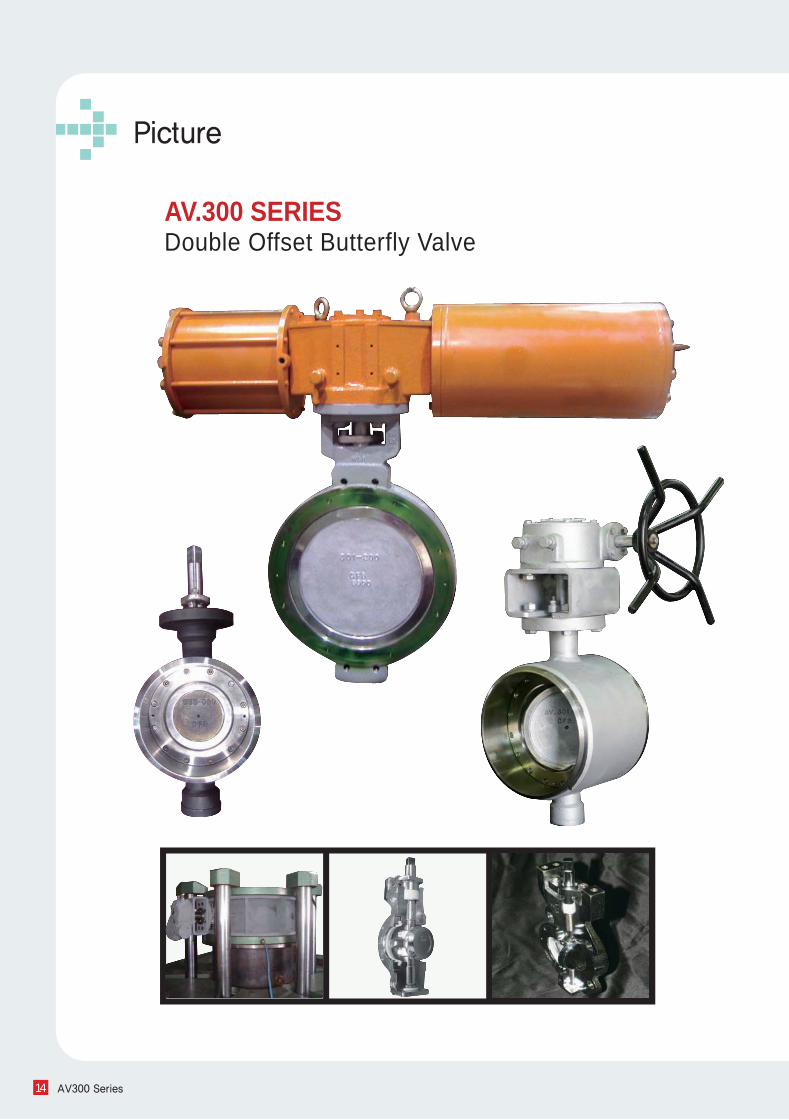
Picture
AV300 Series14
AV.300 SERIESDouble Offset Butterfly Valve
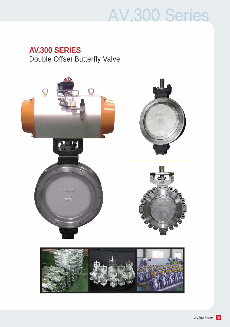
AV.300 Series
AV300 Series 15
AV.300 SERIESDouble Offset Butterfly Valve
Alohan is committed to continuous improvement. All efforts have been taken to maximize the accuracy of this information. Without notification, product specifications and design may be modified at any time. The issue of this document is for information only, and does not imply suitability, a warranty, or guarantee for a specific service.
Alohan Corporation. All Rights Reserved [email protected] www.alohan.co.kr
Our Commitment of Quality


![Untitled-2 [lintasindia.biz]lintasindia.biz/catalogue.pdf · £iïåb STAINLESS STEEL PIPE FITTINGS & VALVES Code No. LI-OIO UNION 1. Threading:- BSP/NPT Grade-CF8 (304)/CF8M (316)](https://static.fdocuments.in/doc/165x107/5ec53785c781e87490220a8b/untitled-2-ib-stainless-steel-pipe-fittings-valves-code-no-li-oio.jpg)


