FULLY AUTONOMOUS CONTROL FOR UNMANNED VEHICLES Northwest UAV

0 | P a g e
AUTONOMOUS UAV DESIGN DOCUMENT
Senior
DesignTeam
10
Faculty Advisor
Matthew Nelson
Client
Space Systems & Controls Laboratory
(SSCL)
Team Members
Anders Nelson (EE) Kshira Nadarajan (CprE)
Mathew Wymore (CprE) Mazdee Masud (EE)
Date Submitted:
December 6, 2010

1 | P a g e
Table of Contents List of Figures 2
List of Tables 2
List of Symbols 2
List of Definitions 3
1. Introductory Material 4
1.1 Executive Summary 4
1.2 Acknowledgement 5
1.3 Problem Statement 5
1.3.1 General Problem Statement 5
1.3.2 General Solution Approach 5
1.4 Operating Environment 6
1.5 Intended Users and Uses 6
1.5.1 Intended Users 6
1.5.2 Intended Uses 6
1.6 Assumptions and Limitations 7
1.6.1 Updated Assumptions List 7
1.6.2 Updated Limitations List 7
1.7 Expected End Product and Other Deliverables 8
2. Approach and Product Design Results 9
2.1 Approach Used 9
2.1.1 Design Objectives 9
2.1.2 Functional Requirements 9
2.1.3 Design Constraints 9
2.1.4 Technical Approach Considerations and Results 10
2.1.5 Testing Approach Considerations 10
2.1.6 Recommendations Regarding Project Continuation 10
2.2 Detailed Design 11
2.2.1 Software System 11
2.2.2 Control System – Controllers 12
2.2.3 Sensor System 20
2.2.4 Power System 21
3. Resources and Schedules 23
3.1 Resources Requirements 23
3.1.1 Personnel Effort Requirements 23
3.1.2 Other Resource Requirements 24
3.1.3 Financial Requirements 24
3.2 Schedules 25
3.2.1 Project Schedule 25
3.2.2 Deliverable Schedule 26
4. Closure Material 27
4.1 Project Team Information 27
4.1.1 Client Information 27
4.1.2 Faculty Advisor Information 27
4.1.3 Student Team Information 27
4.2 Closing Summary 28
4.3 References 29
4.4 Appendices 30
4.4.1 Appendix I – Competition Rules 30
4.4.2 Appendix II – IMU Part Comparison Scoring 32

2 | P a g e
List of Figures Figure 1.3.2 a) System Block Diagram
Figure 2.2.1 a) Software Flow Diagram
Figure 2.2.4 a) Main Control Board – Initial Design
Figure 2.2.4 b) Option 1: System-On-Chip
Figure 2.2.4 c) Option 2: All in one MCU
Figure 2.2.4 d) Option 3: Divide and Conquer MCUs
Figure 2.2.4 e) Draft System Design with Gumstix
Figure 2.2.4 f) Controller Design
Figure 3.2.1 a) Project Schedule
List of Tables
Table 2.2.4 a) Hardware Options Scoring
Table 3.1.1 a) Documentation Expected Labor
Table 3.1.1 b) Design Expected Labor
Table 3.1.1 c) Implementation Expected Labor
Table 3.1.1 d) Labor Totals
Table 3.1.2 a) Components Estimate
Table 3.1.3 a) Financial Summary
List of Symbols C – capacity of a battery
kg – kilograms (unit of mass)
LiPo – Lithium Polymer, a type of battery
mAh – milli-Ampere hours (unit of electric charge)
V – Volts (unit of electromotive force)

3 | P a g e
List of Definitions 466 team – a team of mechanical and aerospace engineers responsible for creating the quadrotor platform
API – Application Programming Interface
GPS – Global Positioning System
IARC – International Aerial Robotics Competition
IMU – Inertial Measurement Unit
JAUS – Joint Architecture for Unmanned Systems
MCU – Microcontroller Unit
RC – Radio Control
RF – Radio Frequency
SSCL – Space Systems and Control Laboratory at Iowa State University
TI – Texas Instruments, an electronic components manufacturer
UAV – Unmanned Aerial Vehicle

4 | P a g e
1. Introductory Material
1.1 Executive Summary
The team will be working on developing the electronics on an unmanned autonomous aerial
vehicle (UAV) for use in the International Aerial Robotics Competition. This competition involves using
the vehicle to penetrate and navigate an office environment to complete tasks outlined in the competition
rules.
Our team will be working with the Space Systems and Control Lab (SSCL) of Iowa State
University as well as a multidisciplinary senior design team from other departments. The other team will
be in charge of developing the platform on which to put the control electronics. In addition, they will be
collaborating with our team regarding the flight dynamics of the platform they deliver. The SSCL will act
as an advising element to the senior design teams and will be providing the funding for the development
of the project.
While designing the electronics of the platform, we conducted research into past competitions and
competitors, and we considered several possible solutions. In this document we will be describing the
decisions we made in choosing the optimal solution for the various problems. Our design consists of five
main modules that will be described later in this document. The general outline is that the UAV will use
sensors such as a laser range finder and an inertial measurement unit (IMU) to collect the data to be used
by the microcontroller system to implement the stability and flight control. In addition to these sensors,
we will also include a communication system to communicate sensor and control data to a base station
that will process the computation-intensive navigation and decision-making algorithms.
The expected end product of the project is a stable flying robot capable of avoiding obstacles. The
robot will be able to stabilize itself using internal inertial measurements and range sensor information.
The product will also include a basic communication module that will be able to communicate data to a
base station that will be able to request information and send control instructions. Since the competition
tasks would require the robot to navigate without a GPS, a mapping functionality will have to be
implemented, possibly by a future team. Thus, easy addition of extra modules like video streaming, object
recognition and extended communication with the remote processing unit is one of our key goals.
The robot will be able to fly for greater than or equal to 10 + 2 minutes without human
interruption or complete loss of power. It shall weigh less than or equal to 1.5 kg.
One of the major issues to be resolved is the flight dynamics itself. As computer and electrical
engineering students, the team shall work in collaboration with another team from Engineering 466
(Multidisciplinary Design) consisting of mechanical and aerospace engineering students. Communication
and co-ordination between the two groups will definitely be a major issue that will have to be carefully
5 | P a g e
worked on. There shall be a single platform delivered by the end of this semester by the 466 team and
sufficient care has to be taken to ensure that the platform does not break during testing.
1.2 Acknowledgement We would like to acknowledge our advisor, Matthew Nelson of the SSCL, for technical advice
and oversight. We would also like to acknowledge Kale Brockmann and the Engineering 466 team for
their help and patience.
1.3 Problem Statement
1.3.1 General Problem Statement The International Aerial Robotics Competition states in its mission that the main motivation
behind this competition is to promote and push the research and implementation of efficient indoor
navigation systems, flight control and autonomy in aerial robots. The problem is that the UAV must be
capable of flying autonomously, i.e., without any real time human control, within an indoor environment
without the aid of GPS navigation techniques. The robot will also be expected to complete a basic set of
tasks, such as identifying and replacing a USB drive (as in previous competitions). These tasks must be
completed within ten minutes. The robot must weigh no more than 1.5kg. Our specific challenge within
the scope of the senior design project is that we have to design and build the onboard electronics and
power systems for a platform that will fly autonomously and implement obstacle avoidance and stability
control.
1.3.2 General Solution Approach
Our solution to this problem is to build a platform that will be able to make most of the important
decisions required for stability control, communication, and power management on board. It will send
other information such as the range finder and image/video data through a wireless link to a remote base
station where the heavy computations such as localization and search algorithms will be implemented. A
control system shall first be developed by which the base station will be able to wirelessly command the
robot to move according to the instructions based on an API developed for this purpose. This API will
allow future implementation of important mapping and search algorithms to enable complete autonomy.
The robot will be tested in a controlled environment where the behavior can be observed and improved. It
is to be noted that our platform will only enable the implementation of localization algorithms and serve
as a functional platform but not implement it.
The following is the general system block diagram that indicates the components that we propose
to implement.

6 | P a g e
Figure 1.3.2 a) System Block Diagram
1.4 Operating Environment The operating environment will be based on the competition set up which imitates the interior of
an office. The environment will be completely indoors as the main objective of the competition is to
achieve efficient indoor navigation. There will not be external factors such as wind or rain since it will be
completely indoors. The robot will also have to navigate without the use of a GPS system. The missions
is intended to be a stealthy one so there shall be no human beings inside the actual office setting where the
robot has to operate.
1.5 Intended Users and Uses
1.5.1 Intended Users
The system will be used by the SSCL team for the IARC competition.
1.5.2 Intended Uses
The system will have a specific purpose of doing the mission outlined in the competition, i.e.
getting inside the secured compound and retrieving the flash drive. However, the scope for this senior
design team is to design the electronics platform to be capable of expansion, without implementation of
the systems that will make it autonomous, mainly, the object recognition and mapping systems of the base
station.

7 | P a g e
1.6 Assumptions and Limitations
1.6.1 Updated Assumptions List
1) The platform delivered to us by the 466 team will be capable of stable flight.
2) Members from the 466 group will continue to work on the chassis and the mechanical details
of the project next semester as a part of 467 or voluntary involvement.
3) No additional money apart from that provided from the SSCL will be required.
4) No major change in the competition mission will take place.
5) This project will be picked up by another team after this year to expand it to the full
autonomy required for the competition.
6) The parts and components that we have agreed upon shall integrate into the system without
any major compatibility issues.
7) The resolution of the inertial unit and other sensors will allow for adequate accuracy in
implementation of complex obstacle avoidance algorithms.
1.6.2 Updated Limitations List 1) The delivered platform will not be able to perform object recognition, but it will enable future
addition of an object recognition system.
2) The robot will not be able to bear any additional weight other than the on-board components.
3) The robot will not be able to hover or stay powered beyond a time period of 12 minutes if the
need for such a situation arises.
4) There will be a single robot platform developed and there will be no backup structure.
5) Since majority of the 466 team will be gone after the first semester, no major changes in the
platform itself will be easily possible.
6) The team has limited time for implementation due to other course studies.
1.7 Expected End Product and Other Deliverables The deliverable for this project is a quadcopter that is capable of stable flight, obstacle avoidance
and remote termination in case of emergency. The platform will also be easily expandable to enable
autonomous navigation. The steps taken to ensure ease of expansion have been indicated in our design
decisions, choice of sensors and the overall physical structure of the platform. For example, the processor
has USB host capabilities to allow for the use of devices such as laser range detectors and portable camera
and vision sensors. The chassis also has been designed to accommodate the weight and volume of the
laser range finder even our group will not be processing the information obtained from this sensor. This
platform will hold power for at least 12 minutes while operating in an indoor environment. The robot will

8 | P a g e
be able to avoid obstacles and balance itself by maintaining an optimal altitude from ground. The robot
will be able to communicate with a base station which will receive sensor data and send back navigation
commands.
A complete documentation manual along with the detailed API specifications will be provided to
the client for ease of control through the base station. The API will specify functions required for the base
station to command the robot to take necessary decisions through a wireless RF communication link.
9 | P a g e
2. Approach and Product Design Results
2.1 Approach Used
2.1.1 Design Objectives
Design the onboard electronics and power systems for an autonomous unmanned aerial vehicle
capable of competing in the IARC
Design the basic onboard software for the abovementioned UAV
Design systems that can be integrated with the vehicle platform designed by an Engineering 466
team
Design systems that can be expanded as part of a competition-worthy UAV by a separate team
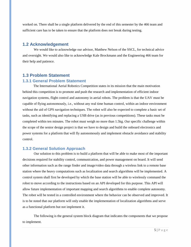
2.1.2 Functional Requirements
Lightweight
o Entire platform under 1.5kg
Low power
o Battery powered
o 10 minutes minimum flight time (12 minute goal)
Four brushless motors at 11V
Electronics systems
Operational
o Onboard stability control
Recovery time goal of three seconds or less
Entirely self-contained hover behavior
o Wireless base station communication
Wireless link capable of at least 42 meters
System capable of JAUS-compliant telemetry
Expandable
o Potential for navigation in a GPS-denied environment
Support for USB laser rangefinder
Considerations for computer vision system
o Potential for executing remote autonomous commands
o Connectivity for manual remote kill switch
o Connectivity for wire-burn USB stick drop-off system
2.1.3 Design Constraints
Compatibility
o Must integrate into 466 team’s vehicle platform
o Must potentially fulfill competition requirements
Time
o Deliverables due in May 2011
o Team has other time-consuming obligations
Experience

10 | P a g e
o Team has limited design experience
o Team has limited implementation experience
Cost
o Budget is supplied by SSCL
o Budget is not definite but definitely limited
2.1.4 Technical Approach Considerations and Results The design of the systems of the platform will be simulated and analyzed. The results of each
simulation will determine the designs and specs that will be considered. The considered design will be
approved and then it will be implemented to get the prototype. The prototype will be tested further and
follow the testing approaches. Upon passing all the testing the final platform will be delivered.
2.1.5 Testing Approach Considerations
The testing will contain 5 different approaches. They are the following:
Stability- This test is on the motors. The responsiveness of the motors will be tested with varying
degrees of external disturbances and the results will be recorded.
Communication – This test is on the communication between the platform and the remote base
station. The distance and the speed of communication will be tested.
Flight control – This test is to determine the accuracy of each command from the various
controls.
Obstacle avoidance- This is the test on the sensors. The reliability and the accuracy of obstacle
avoidance will be tested from the movements of the platform in various directions.
Endurance (Power) - this is the battery testing. The battery will be run under expected load and
voltage over time will be monitored during testing.
2.1.6 Recommendations Regarding Project Continuation The team recommends the continuation of the project as currently planned. The team believes the
proposed design satisfies the requirements and constraints and is ready to begin implementation and
integration into the 466 vehicle platform. Furthermore, the team recommends the assembling of a separate
team to focus on autonomous behavior and navigational programming of the proposed systems.
2.2 Detailed Design
2.2.1 Software System
The software system consists of modules that run of different controllers but work in unison to
provide the end user a friendly API. Currently the software system consists of the following modules:

11 | P a g e
1. Positioning System: This system serves as the part of the navigation block that will be used for
single waypoint navigation. This will be implemented on the base station controller. The
positioning module will eventually require an implemented Simultaneous Localization and
Mapping Algorithm, but our end deliverable will only issue basic commands directing the robot
to move in a given direction for a given distance or speed. The current position and the desired
final position are not determined through mapping, the platform will provide an API to such an
algorithm that will now be able call our functions as long as it provides key information
parameters like speed and direction of motion.
2. Heading: This module will be implemented on the main on- board controller on the robot. It
acquires information from the positioning system and sends commands to the motor controller.
3. Motion Controller: This is the module which controls the motors to achieve the desired
speed/motion. The feedback about the percentage thrust achieved from this module is also sent to
the heading module.
4. Dynamic Stability Control Module: This module uses the data from the internal sensor
consisting of the inertial unit to maintain stability of the robot. It is also possible to integrate
information from external sensors like range detection units such as the IR to combine the
stability control and the obstacle avoidance, but we wanted to modularize our design to minimize
interdependence.
5. Obstacle avoidance module: This module reads the current sensor data and identifies if there is
any obstacle to avoid. If there is, the system is sent back to the motion control state where the
motion parameters are re-calculated based on odometry information. If there is no obstacle, then
the system returns to positioning with a “Final Met” feedback.
Here is a graphical view of the software block diagram consisting of all the modules mentioned above.

12 | P a g e
Figure 2.2.1 a) Software Flow Diagram
2.2.2 Control System – Controllers The control system is the brains of the autonomous UAV. The control system has three main
functions:
It uses sensor data to provide flight via the motor controllers.
It provides a platform for executing autonomous actions needed for the competition.
It communicates with the base station, accepting command decisions and providing data useful in
making those decisions.
In addition, the control system supports manual flight via a hobbyist RC control system, the
implementation of a remote manual kill switch and JAUS-compliant telemetry capabilities. Figure 1.3.2a
is a block diagram of the initial high-level system designed to provide that functionality.
Note that the initial expected inputs of the on-board microcontroller were an IMU and a sensor
array, potentially including IR, sonar and a laser rangefinder. The expected output of the microcontroller

13 | P a g e
was to the four motor controllers of a quadcopter, and a wireless communications unit was expected to
provide communication with the remote processing, as well as kill switch and JAUS functionality. The
camera and vision system was expected to exist separately.
Using these I/O requirements, the following general design for a main control board was created.
Note that the camera was now being considered as a direct input into the microcontroller unit. In later
iterations, the camera system was again made a separate component, as it was considered out of the scope
of this project. Also, a camera system is expected to require dedicated communication channels due to the
high bandwidth and processing power required for transferring and working with video.
Figure 2.2.4 a) Main Control Board - Initial Design
At this point, the issue was raised that, in general, small microcontrollers do not have the USB
host capabilities that would be needed for a USB laser rangefinder.
The team was reluctant to exclude the possibility of a laser rangefinder for use in navigation and
mapping by future teams, and the project advisor agreed. While small laser rangefinders using the RS-232
communications interface do exist, the team found that such lasers are more expensive models, selling for
approximately $1000 more than the USB model the team had found. In the interest of budget and
expandability, the team decided to require the system to support a USB laser rangefinder.
This decision became crucial to the microcontroller system design. System-on-chip/computer-on-
module options were now considered, with the other option being a smaller microcontroller with USB

14 | P a g e
host capabilities, such as the TI Stellaris. At this point, the following three high-level system options were
proposed.
Figure 2.2.4 b) Option 1: System-on-chip
Option 1 featured a system-on-chip module that could run Linux connected to a smaller
microcontroller that would handle flight stability calculations and the output to the motor controllers. This
option was initially thought to be overly large and power-hungry for the project.

15 | P a g e
Figure 2.2.4 c) Option 2: All in one MCU
Option 2 consisted of a single 32-bit microcontroller with USB host capabilities, such as a TI
Stellaris, with a separate communication unit such as an XBee. Although the smallest and most power-
efficient of the three options, this option was considered too rigid, with little room to expand an already-
busy microcontroller.

16 | P a g e
Figure 2.2.4 d) Option 3: Divide and Conquer MCUs
Option 3 was considered to be more favorable with the addition of a separate, smaller
microcontroller for flight stability and a 32-bit USB-host-capable MCU for sensor input and
communications with the RF unit. This option would provide the advantage of sandboxing the flight
stability, allowing the UAV to stay aloft even if the main controller should fail. Also, the flight control

17 | P a g e
unit could be programmed and then left alone, aside from minor performance tweaks, which would be a
major usability boost for a future group implementing autonomous functionality with no knowledge of
the flight control details.
While the team was initially in favor of Option 3, the project advisor encouraged further research
into system-on-chip options. Part of the reasoning behind this decision was that a controller running
Linux would already have USB drivers, hugely simplifying I/O programming. Further research indicated
that many other elements, including wireless communications, power, programming, implementation and
general expandability and usability would be simplified with a system-on-chip device running Linux.
Additionally, the power budget indicated that the power required by the electronics, even a
system-on-chip, would be minor compared to the power used by the motors. The weight budget showed
considerable room for play as well, so those factors, while still important, were of less concern than
initially thought. Thus, the following table comparing and scoring main controller options was produced.
All options considered included USB host capability and a WiFi module.
Table 2.2.4 a) Hardware Options Scoring
Options were scored based on size and weight, power consumption, price and other features for
usability and expandability. The highest score was given to a system from a company named CompuLab.
However, upon contact, the company declined to sell single products to academia. Thus, the Gumstix
Overo Fire, in a system similar to Option 1, became the highest-scoring option.
Meanwhile, a 16-bit PIC MCU from Microchip’s PIC24 series was chosen as the flight controller.
Since many companies offer similar MCUs, a PIC was chosen because of the SSCL’s history of work
18 | P a g e
with PICs, allowing the team to tap into existing equipment resources and an experienced knowledge
base.
The selected PIC fits its purpose well. It features nanoWatt XLP low-power technology and a
wide variety of I/O options, including 25 remappable I/O pins which will allow the team to accommodate
for any sensors which may be connected to the flight controller for basic obstacle detection. Additionally,
the PIC supports the major serial I/O options for interfacing with the main controller and the IMU, as well
as five PWM channels for the motor controllers. And the PIC has five input capture lines, which can be
used for processing signals from a hobbyist RC receiver for manual flight control.
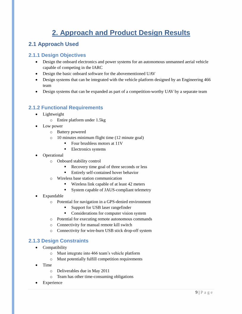
The final iteration of the control system high-level design is shown below. New additions include
the RC receiver and a heartbeat signal between the flight controller and the main controller. This
heartbeat will allow the two controllers to track each other’s presence and take appropriate measures
should either fail.
Figure 2.2.4 e) Draft System Design with Gumstix
19 | P a g e
As proof-of-concept, the team’s research has showed that previous IARC competitors have used
similar systems. The team has arrived at the proposed design independently, so the similarity with other
competitors’ systems is encouraging. Also, the project advisor, who has previous experience in this type
of design, has approved the choices made.
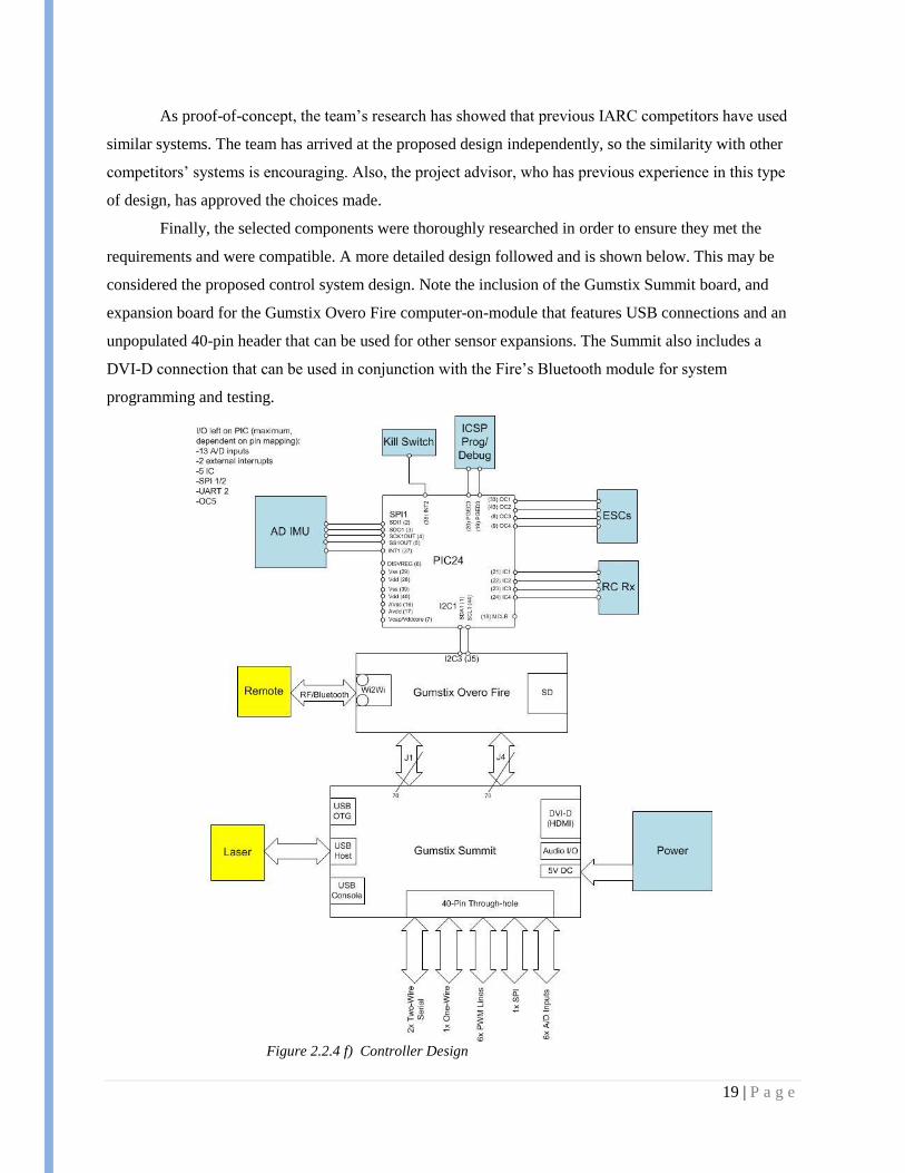
Finally, the selected components were thoroughly researched in order to ensure they met the
requirements and were compatible. A more detailed design followed and is shown below. This may be
considered the proposed control system design. Note the inclusion of the Gumstix Summit board, and
expansion board for the Gumstix Overo Fire computer-on-module that features USB connections and an
unpopulated 40-pin header that can be used for other sensor expansions. The Summit also includes a
DVI-D connection that can be used in conjunction with the Fire’s Bluetooth module for system
programming and testing.
Figure 2.2.4 f) Controller Design

20 | P a g e
2.2.3 Sensor System
The sensor system is composed of two types of sensors: internal sensors that measure the
characteristics of the platform, and external sensors that take measurements of the environment around
the platform.
The internal sensors category is composed of the inertial measurement unit (IMU). The IMUs
looked at for this project were those with a minimum of 6 degrees of freedom. This means that the IMU
allows measurement of acceleration along each of the axis and measurement of rotation about the axis in
3 dimensions. These work as feedback for stable flight control. The IMU that was selected is a 9 degree
of freedom IMU from Analog devices called ADIS16405. This IMU has temperature calibration on the
device and a very high degree of sensitivity. Normally, such a device would be well outside of the budget
for this project. However, we are able to using sampling of the device to get it for next to no cost. This
option serves the project well. A spreadsheet used in the IMU decisions can be found in the appendix.
The external sensors needed for this project would be a range finder for use in navigation, 2
cameras for navigation and object recognition, and short range sensors for basic collision avoidance. The
range finder and cameras have been eliminated from our project scope since navigation algorithms and
object recognition are to be implemented by later teams. The short range sensors will be used as a backup
safety measure in case the navigation system does not see an object it is about to hit. The items for this
will not be purchased. Instead, IR/Sonar sensors from the lab the project is being done through will be
used.
2.2.4 Power System The power system is the main source of operating all the equipment in the autonomous UAV. The
main focus is using a LiPo (Lithium Polymer Battery). This battery will be used for three reasons:
High charge/discharge efficiency
Lightweight
Adaptability to a wide variety of packaging shapes and ruggedness
The power system will be powering the On-Board Micro-controller, the motors of the quad copter, the
IMU, the Sensors and the camera. The block diagram in figure 1.3.2a shows a view of what the power
system connects to.
The LiPo battery that is considered ideal is a 3-cell pack with 11.1V voltage, 6500mAh capacity, and
20C maximum for the continuous current output. There are three main battery options for the quadcopter.
These options are:
Single Pack

21 | P a g e
In this pack the ideal battery that is considered will be in the form of one single pack. It
can be found off the shelf or it can be ordered with the required specifications. The single pack
will consist of 3 cells packed together. Since, this is a huge pack with everything together the
amount of space needed to fit it will be larger.
Series Pack
This is one form of combination pack to meet the requirement of the ideal package. Here,
three separate single cell packs, or 2 cells and 1 single-cell pack will be combined. This will be
done by combination of the different packs to make it a 3 cell pack with 11.1V combined from
each of them. The 6500mAh capacity will be same for all the separate packs with the 20 C
maximum continuous current. This form of packaging will help putting the three cells separately
by accommodating them in suitable space on the platform.
Parallel Pack
This is another form of combination pack that has the similar specifications as the serial
packaging. Also, it will have all the advantages as the serial packaging. In this form of
packaging, 3 single cells will be combined again to form a 3 cell package. Again, 3 single cell
packs, or 2 cell and 1 cell pack will be combined. Every single cell will have the same voltage
i.e. 11.1 V, but the capacity of them will be different and it will be combined to get 6500 mAh,
with a 20C maximum continuous current.

22 | P a g e
3. Resources and Schedules
3.1 Resources Requirements
3.1.1 Personnel Effort Requirements
The requirements in labor that will be used for this project can be broken into 3 main sections.
The sections of labor are in Documentation, Design, and Implementation. These sections can each be
further divided into subtasks that must be accomplished for the overall project. The updated tables below
list out how the tasks will be split between members of the senior design team as well as the totals for
each section of labor.
Documentation Expected Labor
Team Member Project Plan Plan Presentation Design Document Design Presentation Final Documentation Total
Anders Nelson 10 10 15 10 15 60
Mazdee Masud 10 10 15 10 15 60
Mathew Wymore 10 10 15 10 15 60
Kshira Nadarajan 10 10 15 10 15 60
Total 40 40 60 40 60 240
Design Expected Labor
Team Member Past Competitor Research Parts Research&Selection Sensors System Power System Control System Software System Total
Anders Nelson 10 10 15 10 5 0 50
Mazdee Masud 10 10 10 15 5 0 50
Mathew Wymore 10 10 5 0 20 5 50
Kshira Nadarajan 10 10 5 0 5 20 50
Total 40 40 35 25 35 25 200
Implementation Expected LaborTeam Member Control System On-Board Programming Sensor Integration Power System Communication System Parts&Integration Testing Final System Testing Total
Anders Nelson 20 10 15 10 5 40 60 160
Mazdee Masud 20 10 10 15 5 40 60 160
Mathew Wymore 15 30 5 0 10 40 60 160
Kshira Nadarajan 15 30 5 0 10 40 60 160
Total 70 80 35 25 30 160 240 640
Labor TotalsTeam Member Documentation Design Implementation Total
Anders Nelson 60 50 160 270
Mazdee Masud 60 50 160 270
Mathew Wymore 60 50 160 270
Kshira Nadarajan 60 50 160 270
Total 240 200 640 1080
Table 3.1.1 a) Documentation Expected Labor
Table 3.1.1 b) Design Expected Labor
Table 3.1.1 c) Implementation Expected
Labor
Table 3.1.1 d) Labor Totals

23 | P a g e
3.1.2 Other Resource Requirements This section includes the items needed for implementing our project. These are the electronic
components for the platform. This list does not include those items used for implementing the platform
that will be done by the Engr 466 Senior Design Team. This list is an estimate based on items that will be
bought within the coming weeks. Prices for some items may change from the ones listed, but not likely by
much. To note is that the costs of a range finder and cameras are not included in this list.
3.1.3 Financial Requirements
The following is the summary of the financial requirements for this project. This is based on a
labor cost estimate of $20 per hour.
Despite the total of $22,100, only the components cost will need to have funding for. Therefore,
the real financial cost without labor is estimated at around $500 without the cost of the platform designed
by the Engr 466 Senior Design Team or the future components needed for implementing navigation
algorithms and object recognition.
Components EstimatePart Name Est. Cost per Unit Number of Units Total Cost
External Sensors
IR/Sonar Sensors (from Lab) $0.00 3-4 $0.00
Internal Sensors
Analog Devices - ADIS16405 IMU $0.00 1 $0.00
Power
Battery Space 3.3Ah Lipo Battery $59.95 2 $119.90
Recharger/Balancer $49.95 1 $49.95
Microcontrollers
Gumstix Overo Fire COM $219.00 1 $219.00
Gumstix Summit Expansion Board $49.00 1 $49.00
Microchip PIC24 $2.00 1 $2.00
Miscellaneous
Misc. Items (e.g.-wiring, PCB,etc.) $60.00 1 $60.00
Parts Total without Platform: $499.85
Financial SummaryCost source Hours Cost per hour Total
Labor 1080 $20 $21,600
Components $500
Project Total $22,100
Table 3.1.2 a) Components Estimate
Table 3.1.3 a) Financial Summary
24 | P a g e
3.2 Schedules
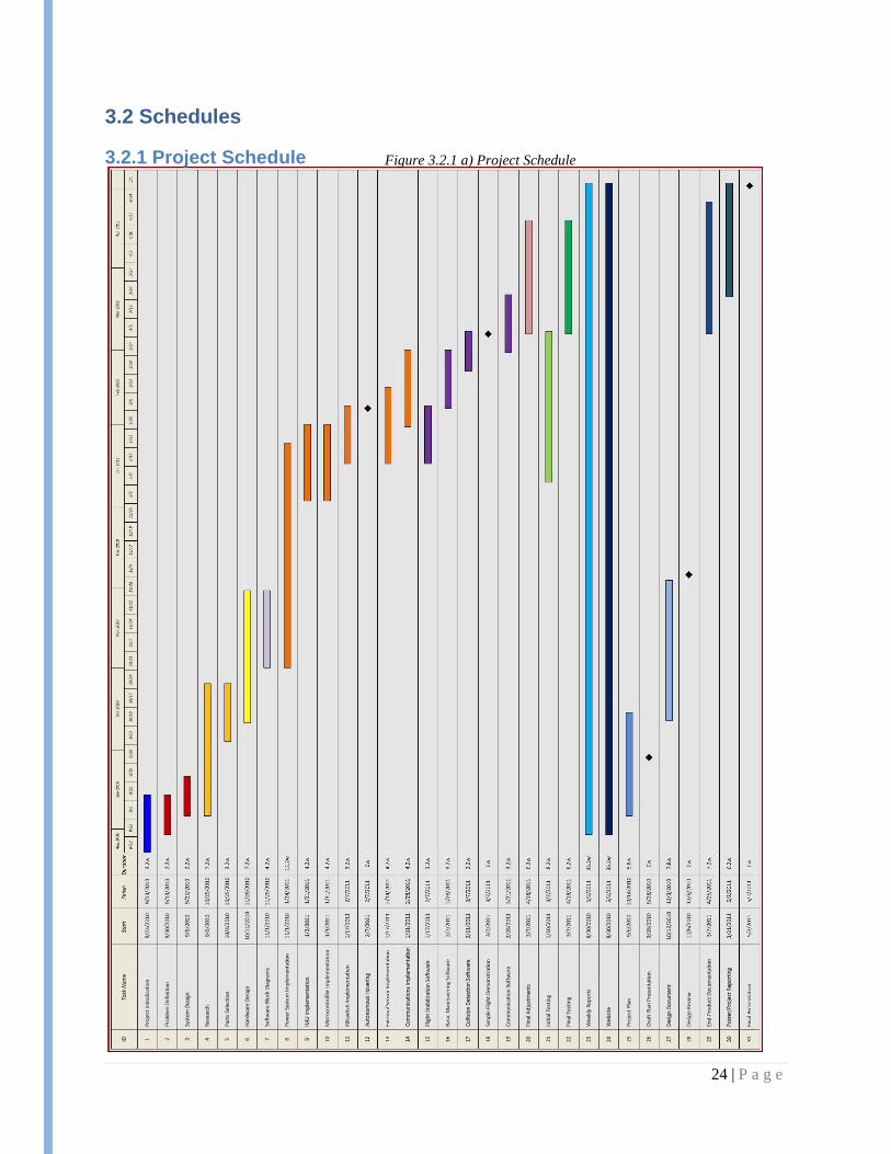
3.2.1 Project Schedule
Figure 3.2.1 a) Project Schedule

25 | P a g e
3.2.2 Deliverable Schedule The deliverables for this project are marked on the schedule by black diamonds. Outside of the
documentation, there are a couple of main checkpoints in the project. They are autonomous hovering and
a simple flight demonstration. The autonomous hovering is set to be completed in February next semester.
A simple flight demonstration will be set to be working during March with final testing, adjustments, and
further extending the capabilities until the end of the semester.
26 | P a g e
4. Closure Material
4.1 Project Team Information
4.1.1 Client Information
The client for this project is the Space systems and Controls Lab. This is a multi-disciplinary lab
in the aerospace department at Iowa State University which runs multiple projects such as High Altitude
Balloon Experiments in Technology, (CySAT) Cyclone SATellite cubesat project, and the Mars Analog
Vehicle for Robotic Inspection & Construction.
The Director of the Lab is Matthew Nelson and he is also the Advisor for our team. The contact
information for the client is:
Space Systems and Controls Lab
2362 Howe Hall
Ames, IA 50011-2271
515-294-2640
4.1.2 Faculty Advisor Information
Our faculty advisor is Matthew Nelson, the Director of the Space Systems and Controls Lab. His
contact information is:
Chief Design & Operations Engineer
Department of Aerospace Engineering
Space Systems & Controls Laboratory
2271 Howe Hall, Room 2331
Iowa State University
Ames, IA 50011-2271
Office: (515) 294-2640
Fax: (515) 294-3262
4.1.3 Student Team Information
The ECpE 491 Senior Design Team website is located at http://seniord.ece.iastate.edu/may1110/.
This site will be updated as the school year continues. The team members are:

28 | P a g e
Mazdee Masud
Iowa State University
Electrical Engineering
131 N. Hyland Avenue #14
Ames, IA-50014
319-431-5804
Anders Nelson
Iowa State University
Electrical Engineering
504 ½ Lynn Avenue
Ames, IA 50014
515-447-8359
Mathew Wymore
Iowa State University
Computer Engineering
1019 Delware Avenue #17
Ames, IA 50014
641-295-5522
Kshira Nadarajan
Iowa State University
Computer Engineering
Ames, IA
The Engr 466 component of the Autonomous UAV Team has the following contact information:
Kale Brockman (466 Team Lead)
Stockli Manuel
Andy Jordan
Karolina Soppela
4.2 Closing Summary The IARC is an exciting, challenging and educational opportunity for its participants. Prize
money aside, Iowa State University and the SSCL stand to gain good reputation if their team fields a
competition-worthy vehicle. This project is an integral part of such a vehicle. The proposed design has
been carefully crafted to meet the requirements set forth by the competition rules, as well as the
constraints imposed by the physical platform.
Furthermore, the design has been created with expandability and usability in mind. With the help
of a base station, a future team can use an implementation of this design to add autonomous navigation
and mapping functionality, as well as object identification, which are key capabilities of a competitive
platform. When combined with the quadrotor vehicle designed by the Engineering 466 team, this project
will truly take flight.

29 | P a g e
4.3 References International Aerial Robotics Competition (IARC) Site. Association for Unmanned Vehicle Systems
International (AUVSI). Web. Retrieved 10 October, 2010. <http://iarc.angel-strike.com/>
Overo Fire COM Product Page. Gumstix Corp. Web. Retrieved 2 December 2010.
<http://www.gumstix.com/store/catalog/product_info.php?products_id=227>
Summit Expansion Board Product Page. Gumstix Corp. Web. Retrieved 2 December 2010.
<http://www.gumstix.com/store/catalog/product_info.php?products_id=215>
Powerizer High Power Polymer Battery Product Page. BatterySpace.com. Web. Retrieved 2 December
2010. <http://www.batteryspace.com/Powerizer-High-Power-Polymer-Battery-11.1v-3300mAh-
36.63Wh-40A-rate.aspx>
ADIS16405: High Precision IMU Product Page. Analog Devices Inc. Web. Retrieved 2 December 2010.
<http://www.analog.com/en/mems/imu/adis16405/products/product.html#ppa_print_table>

30 | P a g e
4.4 Appendices
4.4.1 Appendix I – Competition Rules
The following is an excerpt of the rules from the International Aerial Robotics Competition (IARC)
Mission 6 outline. Mission 6 is the current mission, being held in August 2011.
“ General Rules Governing Entries 1. Vehicles must be unmanned and autonomous. They must compete based on their ability to sense the
semi-structured environment of the Competition Arena. They may be intelligent or pre-programmed, but
they must not be flown by a remote human operator. Any number of air vehicles may be deployed so long
as the gross aggregate weight of each air vehicle does not exceed 1.50 kg.
2. Computational power need not be carried by the air vehicle. Computers operating from standard
commercial power may be set up outside the Competition arena boundary and uni- or bi-directional data
may be transmitted to/from the vehicles in the arena however there shall be no human intervention with
any ground-based systems necessary for autonomous operation (computers, navigation equipment, links,
antennas, etc.).
3. Data links will be by means of radio frequencies in any legal band for the location of the arena.
4. The air vehicle(s) must be free-flying, autonomous, and have no entangling encumbrances such as
tethers. The air vehicle(s) can be of any type. During flight, the maximum dimension of the air vehicle
can not exceed one (1) meter. The maximum takeoff weight of the vehicle cannot exceed 1.50 kg. The
vehicle must be powered by means of an electric motor using a battery, capacitor, or fuel cell as a source
of energy. The vehicle must be equipped with a method of manually-activated remote override of the
primary propulsion system.
5. A maximum of two (2) non-line-of-sight (NLOS) navigation aids may be used external to the
designated flight area. It will be assumed that these navigation aids were positioned by a mother ship
around the building (but not on top) prior to a aerial robotic sub vehicle launch. The navigation aids must
be portable, and must be removed once the team leaves the competition area. GPS is not allowed as a
navigation aid.
6. The aerial robotic system is required to be able to send vehicle status and navigation solutions to the
Judge’s remote JAUS-compliant data terminal via the JAUS protocol. This will be done according to the
JAUS Standard Set which will be provided to all official teams. Imagery may be delivered to a separate
team-supplied terminal using JAUS protocols but other signal formats will also be acceptable. Similarly,
kill switch transmissions may use JAUS protocols, but can be achieved by other means without penalty. If
more than one aerial robot is deployed simultaneously, intercommunication between the aerial robots may
be by any means and any protocol desired. 7. Upon entering the arena under autonomous control, aerial robots must remain within the bounds of the
arena or the attempt will end. Vehicles leaving the arena or in the Judges’ opinion, are about the leave the
arena, will have their flight terminated by a Judge. Flight termination actuation will be controlled by a
Judge, not the team. Each team will supply the designated Judge with its manually-actuated kill device as
they enter the arena prior to their attempt(s), and must demonstrate that the kill switch is functional for the
Judge. Either separate kill switches can be provided for each vehicle in multiple vehicle swarms, or a
single kill switch that disables all vehicles in the swarm simultaneously is deemed acceptable.
8. The ground station equipment other than the optional navigation aids, manual kill switch mechanisms,
and Judges’ JAUS-compliant terminal interface must be portable such that it can be setup and removed
from the arena quickly. A suggestion would be to setup the equipment on a roll-cart similar to that shown
in Figure 1.

31 | P a g e
Figure 1. Roll-Cart.
Operations Teams will be given four (4) flight attempts. The team with the highest static judging score will be given
one (1) additional attempt. Each team will be given 15 minutes to setup their system and adjust
parameters. If the team is unable to launch an aerial robot within the 15 minute window, the attempt is
forfeited. Each team is granted one (1) pass. Once a set of attempts has been completed by a given team,
the entire team will be required to leave the arena. No hardware may be left in place.
During the static display of the vehicle(s), the vehicle(s) will be measured to verify the 1 meter maximum
dimension constraint. The vehicle(s), in takeoff configuration will be weighed to verify the 1.50 kg
maximum weight restriction. The vehicle(s) will also be examined to assure that all kill switch functions
are fully operational prior to flight.
Competition Area The competition flight area (arena) will be constructed within an area that is approximately 30 m long by
15 m wide, and 2.5 m high. This area will be divided into a number of rooms and corridors with various
obstacles of various heights. The launch location will be fixed at a distance of 3m and oriented toward a 1
x 1 meter (minimum) opening into a corridor. Navigation aids, if used, may be located anywhere in a 3
meter perimeter bounding the outside of the arena (see Figure 2). A list of typical materials and
construction notes (which may be updated from time to time) is provided at http://iarc.angel-
strike.com/IARC_Arena_Construction.pdf so that teams can construct similar practice arenas for use in
refining their aerial robotic systems prior to arrival on the Competition day.”

32 | P a g e
4.4.2 Appendix II – IMU Part Comparison Scoring
IMU Comparison Power (mW) Score Weight (g) Score Volume (cubic cm) Score Resolution Score
Name/Company
Atomic IMU 6 DoF - XBee Ready 81.6 1 2 43.475 1 .00403g/tick-Low, .977deg./tick1
IMU 6DOF Razor - Ultra-Thin IMU 36.3 2 2 5.61 2 .83-3.33mV/deg/s, 300mV/g 1
9 Degrees of Freedom - Razor IMU - 16MHz 44.0385 2 2 14 2 300deg/s 2
IMU 6 Degrees of Freedom - v4 with Bluetooth® Capability 555 -2 2 43.68 1 500deg/s 3
Memsense customized solutions High -3 0 1 3
LandMark™ 21 IMU - 1 Cubic Inch "LN Series" 1419 -3 55 0 16.4 2 3
ADIS16405: High Precision Tri-Axis Gyroscope, Accelerometer, Magnetometer75 1 0 29.0928 1 .0125degree/s/lsb 4
<50 : 2 50-100 : 1
100-200 : 0 200-400:-1
400-800 : -2 800+ : -3
Negligable: 2
>50g : 0 <25: 2 25-50:1 50+:0
Price ($) Score Score (output)
Additional Features
Past Required Source
Digital: 2
Analog: 0 TOTAL SCORE
99.95 1 2 8 http://www.sparkfun.com/commerce/product_info.php?products_id=9184
89.95 1 0 8 http://www.sparkfun.com/commerce/product_info.php?products_id=9431
124.95 0 2 1 11 http://www.sparkfun.com/commerce/product_info.php?products_id=9623
449.95 -2 2 1 5 http://www.sparkfun.com/commerce/product_info.php?products_id=8454
Contact for pricing -2 2 1 http://www.memsense.com/
?? -1 2 3 http://www.gladiatortechnologies.com/PRODUCTS/IMU/product_LandMark21_IMU_LN_Series.htm
700(0) 2 2 3 13 http://www.analog.com/en/mems/imu/adis16405/products/product.html
<50 : 2 50-100:1
100-200:0 200-300: -1
300+: -2