autonomous stable flight wong yu - Cornell University project/stephen_wong... · Autonomous Stable...
7
Abstract—This project aimed to create a stable flight system for a model airplane using a microcontroller, an accelerometer and a gyroscope. The method of stable flight is a PID controller. The hardware was designed to be light-weight and flight ready. The sensors were tested using various validation methods. The robot was then test flown to gather data to create a classifier for the PID constants. I. INTRODUCTION UAVs (unmanned aerial vehicles) are gaining traction in the use of research, transport and combat. This project aimed to develop an UAV system for CU Air, the Cornell University Autonomous flight team. We had initially planned on creating a system that could autonomously fly to set GPS coordinates, but due to time constraints, we significantly limited the scope of our project. Thus, this project focused on the stable flight aspect of autonomous flight using a PID (proportional, integral and derivative) controller. We paired this system with a 6-foot wingspan hobby airplane for testing purposes. Figure 0: Plane robot before a flight. II. HARDWARE DESIGN A large portion of our robot was based on hardware design. Because the system we used had to be light weight and sturdy, we went through several hardware designs before settling on our final design. It is worth noting that all the designs centered around the LPC2378 microcontroller [1] by NXP which was mounted to an MCB2300 [2] evaluation board from Keil (See Figure 1). In this section we will discuss our initial designs, why they were not used and the final design. A. Initial Design Basically, two designs were initially considered and partially tested before they were deemed unfit for our purposes. These two designs will be referred to as the first design and the second design. 1. First Design Our first design involved using the USB port on the evaluation board to communicate with the ground via a USB to WiFi device server [3] . This device server converts USB 2.0 signals into 802.11b or g WiFi. From there a router on the ground relays the signal to a computer. To allow the device server to be used in the air, it was modified with a high gain antenna and a 5 volt voltage was used to power it. The microcontroller would act as a serial to USB converter—thus, allowing the serial messages to be sent through WiFi, to the device server, to the ground. Issues Early on this design was dropped due to weight issues. The plane we had planned on using was not large enough to house all these components, and the engine on this plane was not powerful enough to provide lift for such a payload. From here we decided to focus on reading flight data via sensors on the plane. 2. Second Design Our second design focused on both long-range wireless communications and reading sensors. For the wireless communication portion, we would use a radio frequency serial data transfer device. One end would transmit data and the other Autonomous Stable Flight with a PID Controller Stephen Wong and Jennifer Yu
Transcript of autonomous stable flight wong yu - Cornell University project/stephen_wong... · Autonomous Stable...

Abstract—This project aimed to create a stable flight system for a model airplane using a microcontroller, an accelerometer and a gyroscope. The method of stable flight is a PID controller. The hardware was designed to be light-weight and flight ready. The sensors were tested using various validation methods. The robot was then test flown to gather data to create a classifier for the PID constants.
I. INTRODUCTION
UAVs (unmanned aerial vehicles) are gaining traction in the use of research, transport and combat. This project aimed to develop an UAV system for CU Air, the Cornell University Autonomous flight team. We had initially planned on creating a system that could autonomously fly to set GPS coordinates, but due to time constraints, we significantly limited the scope of our project.
Thus, this project focused on the stable flight aspect of autonomous flight using a PID (proportional, integral and derivative) controller. We paired this system with a 6-foot wingspan hobby airplane for testing purposes.
Figure 0: Plane robot before a flight.
II. HARDWARE DESIGN A large portion of our robot was based on
hardware design. Because the system we used had to be light weight and sturdy, we went through
several hardware designs before settling on our final design. It is worth noting that all the designs centered around the LPC2378 microcontroller[1] by NXP which was mounted to an MCB2300[2] evaluation board from Keil (See Figure 1). In this section we will discuss our initial designs, why they were not used and the final design.
A. Initial Design Basically, two designs were initially considered
and partially tested before they were deemed unfit for our purposes. These two designs will be referred to as the first design and the second design.
1. First Design Our first design involved using the USB port on
the evaluation board to communicate with the ground via a USB to WiFi device server[3]. This device server converts USB 2.0 signals into 802.11b or g WiFi. From there a router on the ground relays the signal to a computer. To allow the device server to be used in the air, it was modified with a high gain antenna and a 5 volt voltage was used to power it. The microcontroller would act as a serial to USB converter—thus, allowing the serial messages to be sent through WiFi, to the device server, to the ground.
Issues Early on this design was dropped due to weight
issues. The plane we had planned on using was not large enough to house all these components, and the engine on this plane was not powerful enough to provide lift for such a payload. From here we decided to focus on reading flight data via sensors on the plane.
2. Second Design Our second design focused on both long-range
wireless communications and reading sensors. For the wireless communication portion, we would use a radio frequency serial data transfer device. One end would transmit data and the other
Autonomous Stable Flight with a PID Controller Stephen Wong and Jennifer Yu

would receive data. These two devices would have to be switched depending on whether we were logging data or flying autonomously. These two devices were much smaller in size and weight and suitable for our plane.
On the sensor side we purchased a 2-axis accelerometer, a gyroscope and two barometric pressure sensors. The accelerometer would measure the x and y orientation of the plane, or the pitch and the roll, respectively. The gyroscope would be used to determine angular velocity in both directions. Finally the barometric sensors would be used to measure the altitude and airspeed of the aircraft.
Issues This design did not work out due to time and
skill constraints. We did not have the skill or time to integrate the two barometric sensors into our board. In terms of skill, a copper-clad board was etched for the pressure sensors, but the leads were too tiny to solder (See Figure 2). Because of this difficulty and the fact that the deadline was approaching we chose not to use them. Also, the accelerometers and gyroscope did not verify according to the outputs specified on their datasheets.
Despite the main three sensors not verifying, we decided to keep them to and look into the matter. Our second design ultimately evolved into our final design.
B. Final Design Our final design takes many elements from our
second design but focuses on validation. The three main components: sensors, RF serial transmitter/receiver and manual override, all had to be validated. This section will discuss the issues involved with validating each of these components.
1. Sensors and Voltage Source
To address the problem of sensor validation, we verified the voltages coming from each sensor, the voltages being read by the board and the reference voltage for the analog to digital converter on our microcontroller. The reference voltage was not the 3.3 V that was expected of our board. We then
checked the source voltage to the board and discovered that it was receiving 4.8 V instead of the 5 V it was rated at.
By connecting a 5 V battery to the board and sensors, we were able to keep the voltage above 5 V, but this still left us with a variable voltage source. We finally settled on a LM7805[4] voltage regulator and a 12 V battery. This way, as long as the capacity of the battery remained between 9 V and 12 V we would receive a constant supply of 5 V. The outputs of this voltage regulation were used to drive the accelerometer, gyroscope, servo motors and the RF serial transmitter (See Figure 3).
Another issue with the voltage source was the noise created by the current draw of the servo motors. To reduce this noise in the voltage source we used a decoupling capacitor of 0.1 µF in parallel with the 5 V regulator output. The schematic for this part of our final design can be seen in Figure 3.
2. RF Serial Transmitter/Receiver
The RF serial transmitter and receiver were easy to validate in one direction, but not the other. In sending data from the plane to the ground they worked as described, but we were limited in our ability to send data to the plane. The issue was that a null modem cable was required to communicate in the other direction. While we had access to a male-to-male null modem cable, a female-to-female null modem cable was not easily obtainable. Also, placing a standard 3-foot null modem cable on the plane would have added unnecessary weight. Because of time limitations, we were not able to send data back to the plane, but we were able to log data.
3. Manual Override
One part of our robot that is essential, but has not been discussed yet, is the manual override. In the case that autonomous flight is not functioning as desired we would like the pilot to be able to override the controls on the plane at any time. To implement this, we multiplexed the control for the ailerons of the plane between the microcontroller

and the pilot inputs. Hardware-wise, this setup was simple to implement and validate.
To validate, we simply switched the control bit on the multiplexor and determined which device was controlling the surfaces. Once the code was in place, the hardware was functioning in every trial of the override.
C. Figures
Figure 1: Keil MCB2300 evaluation board with voltage
regulator and RF serial transmitter.
Figure 2: Barometric pressure sensor board layout.
Figures 3: Schematic for the voltage regulator outputs.
III. SENSOR VALIDATION To validate our sensors, we did a number of
rigorous tests. These tests involved driving with the accelerometer to determine distance traveled, tilting the accelerometer to 90º to determine a value for gravity, turning the accelerometer 180º in 5º segments to test angle accuracy and turning the gyroscope to verify angular velocity.
There was a lot of noise coming from the ADC conversion on the microcontroller. The board does 10-bit conversion time >= 2.44 microseconds[1], but we decided to average 8 ADC conversions before storing a value. So the actual conversion rate became 8*2.44 microseconds. This along with the hardware methods described earlier also helped with noise.
We will now display and explain the results of our validation.
A. Distance Test This test involved driving for about 200 feet with
the accelerometer pointing in the direction of

travel. The following plots detail the results of the x-accelerometer.
Plot 0: The x-acceleration reading, negative is forward.
The results are reasonable because the driver attempted a constant acceleration.
Plot 1: The velocity was obtained after one integration.
Plot 2: The distance traveled was obtained after the
second integration. It can be seen that the accelerometer was reasonably accurate in estimating the distance
traveled.
B. Gravity Test This test involved holding the accelerometer at
90º and measuring the acceleration value, which should be about 32 ft/s2. The following plots detail the results.
Plots 3 & 4: Y-axis acceleration due to gravity. The RMS
values for these two tests were low.
Plots 5 & 6: X-axis acceleration due to gravity. The RMS values for these two tests were also low, but not as accurate
compared to the y-axis.
C. Tilt Test This test involved rotating the accelerometer
between -90º and 90º in 5º segments to validate the tilt readings of the accelerometers. The following plots detail the results.
Plot 7: X-axis accelerometer tilt test results.
Plot 8: Y-axis accelerometer tilt test results.
We also tried to see what tilt values our sensors were getting in order to test the range of our sensors. This test was subject to a lot of human error because we cannot hold the sensor perfectly at an angle. Near +/- 90 degrees range, the sensors were not very sensitive.
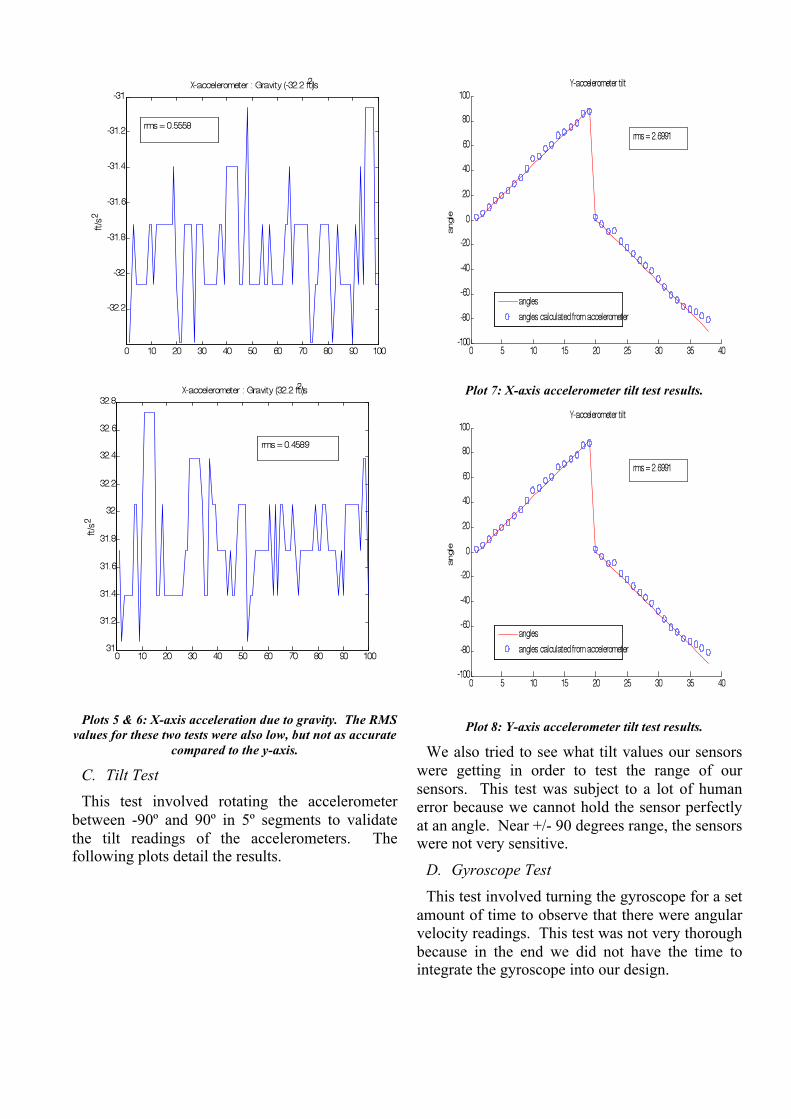
D. Gyroscope Test This test involved turning the gyroscope for a set
amount of time to observe that there were angular velocity readings. This test was not very thorough because in the end we did not have the time to integrate the gyroscope into our design.
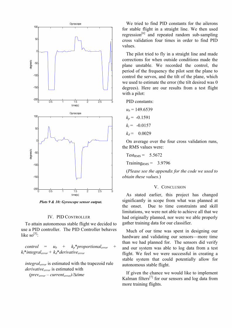
Plots 9 & 10: Gyroscope sensor output.
IV. PID CONTROLLER To attain autonomous stable flight we decided to
use a PID controller. The PID Controller behaves like so[5]:
control = ub + kp*proportionalerror +
ki*integralerror + kd*derivativeerror
integralerror is estimated with the trapezoid rule derivativeerror is estimated with
(preverror – currenterror)/∆time
We tried to find PID constants for the ailerons for stable flight in a straight line. We then used regression[6] and repeated random sub-sampling cross validation four times in order to find PID values.
The pilot tried to fly in a straight line and made corrections for when outside conditions made the plane unstable. We recorded the control, the period of the frequency the pilot sent the plane to control the servos, and the tilt of the plane, which we used to estimate the error (the tilt desired was 0 degrees). Here are our results from a test flight with a pilot:
PID constants:
ub = 149.6539
kp = -0.1591
ki = -0.0157
kd = 0.0029
On average over the four cross validation runs, the RMS values were:
TestRMS = 5.5672
TrainingRMS = 3.9796
(Please see the appendix for the code we used to obtain these values.)
V. CONCLUSION
As stated earlier, this project has changed significantly in scope from what was planned at the onset. Due to time constraints and skill limitations, we were not able to achieve all that we had originally planned, nor were we able properly gather training data for our classifier.
Much of our time was spent in designing our hardware and validating our sensors—more time than we had planned for. The sensors did verify and our system was able to log data from a test flight. We feel we were successful in creating a stable system that could potentially allow for autonomous stable flight.
If given the chance we would like to implement Kalman filters[7] for our sensors and log data from more training flights.

APPENDIX Matlab code for regression: %{ X=[prop_err int_err der_err] }% function [test_rms,train_rms,k] =
regression(y,X,testsize) %split into train and test ran = ceil(rand(testsize,1)*size(X,1)); test_y = y(ran); test_X = X(ran,:); train_y = []; train_X = []; for i =1:size(X,1) if(sum(i==ran) == 0) train_y = [train_y;y(i)]; train_X = [train_X;X(i,:)]; end end k =
(train_X'*train_X)\(train_X'*train_y); y_guess = test_X*k; %[test_y y_guess] test_rms = sqrt(sum((y_guess-
test_y).^2/(testsize))); y_guess = train_X*k; %[train_y y_guess] train_rms = sqrt(sum((y_guess-
train_y).^2/(size(X,1)))); function [test_rms,train_rms,k] =
cross_validation(y,X,testsize,times) avg_test_rms =0; avg_train_rms = 0; avg_k = []; for i=1:times [test_rms,train_rms,k] =
regression(y,X,testsize); avg_test_rms = [avg_test_rms
test_rms]; avg_train_rms = [avg_train_rms
train_rms]; avg_k = [avg_k k]; end avg_k test_rms = mean(avg_test_rms); train_rms = mean(avg_train_rms); k = mean(avg_k,2);
ACKNOWLEDGMENT We would like to acknowledge Professor
Ashutosh Saxena and Mark Verheggen, for giving us advice on the direction of our project, and Matthew Lorhal for his time in piloting the plane for our test flight. We would like to thank National Instruments for donating the Keil MCB2300 for our use. We would also like to thank the CU Air project team and Cornell University.
REFERENCES [1] "LPC2378 User Manual."
http://www.keil.com/dd/docs/datashts/philips/lpc23xx_um.pdf [2] "MCB 2300 Evaluation Board."
http://www.keil.com/mcb2300/mcb2370.asp [3] "Silex SX-2000WG Device Server."
http://www.silexamerica.com/products/usb_device_connectivity/sx-2000wg.html
[4] "LM7805 Datasheet." http://www.datasheetcatalog.org/datasheet/fairchild/LM7805.pdf
[5] Saxena, Ashutosh. "Linear Systems, PID Control." Lecture, CS 4758 Robot Learning at Cornell University, Ithaca, NY, February 16, 2010.
[6] Saxena, Ashutosh. "Projects, Supervised Learning, Linear Regression, Nearest neighbors." Lecture, CS 4758 Robot Learning at Cornell University, Ithaca, NY, February 4, 2010.
[7] Saxena, Ashutosh. "Kalman Filters." Lecture, CS 4758 Robot Learning at Cornell University, Ithaca, NY, March 30, 2010.