Geometrix Automation & Robotic Solutions, Maharashtra,Automation And Robotic Solutions

1
Autonomous Robotic Boat of ENSIETAJan SLIWKA, Pierre-Henri REILHAC, Richard LELOUP, Pierre CREPIER, Henry DE
MALET, Patrick SITTARAMANE, Fabrice LE BARS, Kostia RONCIN, Bruno AIZIER, LucJAULIN et al.
E-mail: "name's �rst 6 letters + surname's �rst 2 letters"@ensieta.frexample: [email protected]
(WRSC/IRSC-2009 Paper)
Abstract�This year, we launched MicroTransatProject in our school to prepare the next year transat-lantic race. In this article we will talk about thesolutions in mechanics, electronics, sailing strategiesand simulation that we developed for our autonomousrobotic boat. As for the mechanics, the hull is home-made using mainly glass �ber mat bound togetherwith a resin binder. As for the electronics, we triedto use off-the-shelf components as much as possibleto ensure the maintainability of the system. In orderto test the sailing algorithm we are using a simulatormade with SCILAB.
Index Terms�Autonomous, Sailing boat,WRSC/IRSC 2009.
Fig. 1. Our robotic boat
I. ABOUT OUR PARTICIPATION IN THE WRSCThis year, our school ENSIETA (French Graduate
Engineering School) has launched the project ofparticipating in the MicroTransat challenge. Manyfactors helped in the project creation. First, ENSI-ETA is located in Brest, a city on the North-Westof France on the Atlantic ocean shore. Moreover,our school is multidisciplinary since there are de-partments of informatics, electronics and mechan-ics and particularly the sub-department of navalarchitecture. Because ENSIETA take part of thechallenge for the �rst time, we will not participatethis year in the real challenge. However, we willbe participating next year for sure (if nobody hadcrossed the Atlantic of course).
Fig. 2. Brest harbour
In order to gain some experience and �nd spon-sors for the real challenge, we decided to makea smaller intermediate private challenge of au-tonomously crossing the Brest harbour (see �gure

2
2). For that purpose we are building a small boat1m20 long that will only be able to do shortdistances. As for an of�cial challenge, instead ofMicroTransat , the WRSC will be the �rst of�cialchallenge for our small boat.
II. OUR FIRST ROBOTA. Mechanical design and construction
Fig. 3. IMOCA Class
Our sailing robot design is based on the IMOCAclass design (race boats see �gure 3). We only madethe mast smaller in order to enhance its stability.The next sub-parts will talk about the mechanical
architecture.
Fig. 4. Created using Delftship (free version)
1) Hull construction: In order to build the hullwe used the following steps.
� Create a mould with a form corresponding tothe hull using plaster.
� Cover the inside of the mould with a specialresin in order to be able to remove the hullfrom it
� Put some Gel Coat and obtain the result in�gure 5-(a).
� Put 2 layers of glass �ber mat bound togetherwith a resin binder (�gure 5-(b)).
� Extract the hull (�gure 5-(c)) and add theinternal structure elements using wood andglass �ber mat bound together with a resinbinder (�gure 5-(d)).
Fig. 5. Hull construction
2) Waterproofness: The deck normally seals wellenough the inside of the boat. However, we wouldlike to be able to remove the electronics fromthe inside of the boat for maintenance and debugpurposes. This creates waterproofness problems. Wesolved this problem using a waterproof box andSwitchcraft waterproof connectors (see the �gure6). In fact, we cut a rectangular hole in the deckin which we put the box. Then we cut the box'sbottom and glued the borders of the box to the deckwith special glue. The communication between theexternal sensors and the inside electronics is made

3
through waterproof connectors.
Fig. 6. Waterproofness
3) Mast: As for the mast, we used an aluminummast ordered in Germany. It is a pro�led mast witha groove for the sail.4) Sail: The sail is not triangular but has the
form as in the �gure 7 in order to lower the windforce application point keeping the same ef�ciencybut at the same time rising the stability of the boat.
Fig. 7. Sail
5) Rudder blade: Like in the IMOCA classboats, there will be two rudder blades to allowsteering even when the boat is leaning sideways.
6) Servos: Because the boat is designed for shortdistances, we do not need resistant servomotors. Weused rc-model servos.7) Keel: The keel's lead bulb was cast using a
mould as you see the �gure 8.
Fig. 8. Bulb mould
B. Autonomous boat electronics1) Solutions:
Fig. 9. Electronic architecture
While designing our electronics (�gure 9), wehave �rst thought of the solution shown in the �gure10.Even if we didn't chose this approach, it is an
interesting one. In fact, the solution is based on twoprinciples:

4
� Use of COTS (Commercial off-the-shelf) ele-ments
� Use most integrated elements (that do most ofthe tasks as the Neo and the Labjack)
In fact, the Neo Freerunner is a mobile phonewith an LCD touch screen. Besides a GSM commu-nication module, the Neo has WIFI and Bluetooth,useful for debugging and con�guration, a GPS, 2Accelerometers and an embedded Linux Debianallowing an easy programming (In C/C++ languageusing standard libraries).
Fig. 10. Old solution
The other "universal" component is the Labjackthat makes the interface between the Neo andthe Sensors/Actuators. This component has severaldigital I/O, ADC (Analog to Digital Converter) andDAC (Digital to Analog Converter). It can alsoconnect to an I2C bus.We were able to make this solution work properly
with a robotic car. But the problem is the complex-ity of the Neo. In fact, because there is an embeddedLinux, the system has to boot when powered. Thiscauses problems since sometimes the system werenot working properly after rebooting. However, thisapproach is promising since it provides with high
quality integrated systems at a good price. Besides,the development of electronics becomes very simplesince we can add a new sensor just by connectingit to the Labjack and writing the program thatmanages the data acquisition.As for our current architecture, we used more
components that have exactly the same behaviorwhen rebooted and have lesser power consumption.In fact, we are preparing the electronics for thetransatlantic race where rebooting might be frequentdue to frequent power shortage.
Fig. 11. New solution
2) GPS: As for the GPS we used the EB-85A(FV-M8). In fact, this GPS is small and has goodprecision.3) Compass: We used the HMC6352 Compass
module since it has one degree resolution.4) Intelligence: We used a PIC18F2550 from
Microchip mounted on the 28-pin Pickit demoboard [8]. We have chosen the PIC since it is morerobust to power shortage (no booting) and use lessenergy than the Neo Freerunner.5) Energy source: As for now, the energy source
are lithium polymer batteries (�gure 12) from RC-Systems that will be suf�cient for crossing the Brest

5
harbour and might even be suf�cient to do the 48hWRSC race. Regarding the progress of the project,we will start the development of the solar energymodule.
Fig. 12. Lithium Polymere battery
6) Communication: Even if the boat is supposedto be autonomous, we need a way to communicatewith it for debug and con�guration purposes. Weuse two Adeunis ARF53 HF modems (one oneach side). This modem is long-range and can becontrolled by the PIC and the base PC throughRS232. At �rst, we wanted to use the GSM/GPRS(�gure 13-(b)) but we would have to pay for thesubscription fee for the GPRS data line both forthe boat phone and the PC modem so we gave upon this solution.As for the MicroTransat challenge we might
use IRIDIUM modem (�gure 13-(c)) or the SPOTmessenger(�gure 13-(a), found at the MicroTransatmailing list!). In fact, the SPOT messenger is alot cheaper and gives the possibility to track theposition of the robotic boat using E-mail or GSMphone.
Fig. 13. Communication modules
7) Servo control: At �rst, we wanted to controlthe servos directly from the PIC but it used toomuch of its resources so we decided to add a
separate servo controller. As for now, we will use ahomemade servo controller. In order to increase thereliability, we might use COTS IC as the POLOLUor PARALLAX (�gure 14-(a) and 14-(b) resp.).
Fig. 14. Servocontrollers
8) Anemometer: We will use the CV7 ultrasonicanemometer from LCJ Capteurs. We avoid usingmechanical anemometers since there are more likelyto break.9) Reliability: We are trying to make the boat
able to move forward using only the GPS. The othersensors would only increase the accuracy of theactions. As an example, if the anemometer stopsworking, we will have to infer the wind orientationfrom the GPS position/speed and the COMPASS.The trick is to stop the boat. A immobile boat willautomatically take a speci�c orientation from whichwe can infer the wind orientation.We are still working on that kind of aspects so
we do not have any results yet.
C. Sailing algorithmIn order to test our algorithms, we are using a
simulator written in SCILAB language. The sailingboat represented is described by the following stateequations8>>>>>>>>>>>>><>>>>>>>>>>>>>:
_x = v cos �; (i)_y = v sin � � �V; (ii)_� = !; (iii)_�s = u1; (iv)_�r = u2; (v)_v =
fs sin �s�fr sin �r��fvm ; (vi)
_! = (`�rs cos �s)fs�rr cos �rfr���!J ; (vii)
fs = �s (V cos (� + �s)� v sin �s) ; (viii)fr = �rv sin �r: (ix)

6
The inputs u1 and u2 of the systems are thederivatives of the angles �s and �r. The state vectorx = (x; y; �; �s; �r; v; !)
T 2 R7 is composed with� the coordinates x; y of the inertial center G ofthe boat
� the orientation �,� the sail angle �s� the rudder angle �r� the tangential speed of G� the angular velocity ! of the boat around G.The intermediate variables are� the thrust force fs of the wind on the sail,� the force fr of the water on the rudder.The parameters (that are assumed to be known)
are� the speed V of the wind,� the distance rr between the rudder and G,� the distance rs between the mast and G,� the rudder lift �r,� the sail lift �s,� the tangential friction �f of the boat withrespect to the water,
� the angular friction �� of the boat with respectto the water,
� the angular inertia J of the boat,� the distance ` between the mast and the thrustcenter of the sail,
� and the drift coef�cient �.These parameters will be chosen as
� = 0:05; rs = 1; rr = 2; V = 10;
m = 1000; J = 2000; �f 2 60;�� 2 500; �s = 500; �r = 300:
We simulate the behaviour of the boat using Eulerapproximation.
x(t+ dt) = dt � f(x) + x(t)
f represents the state equations.In order to be able to develop strategies, we �rst
need a regulator that regulates the boat's sail angle�s and orientation � to a speci�c target (�̂s; �̂). (seearticle [1] for more details)
u = r (x;w) = r(x;�̂s; �̂)
As for the strategies, in order to sail to a speci�cwaypoint, we can use a hybrid second stage reg-ulator. In �gure 15, we can see the four differentdirections �i to follow that will be chosen by theregulator with regards to the position of the boatwith regards to the target. Denote by �hr the currentdirection to be followed by the hybrid regulator. Forexample, if the boat is in zone q = 3 then �hr = �3.The target orientation �̂ will the �ltered response of�hr with a �rst order �lter in order to avoid brutaltransitions of �̂. The sail angle depends directly ofthe orientation �̂s = h(�̂).
Fig. 15. Four possible target orientations
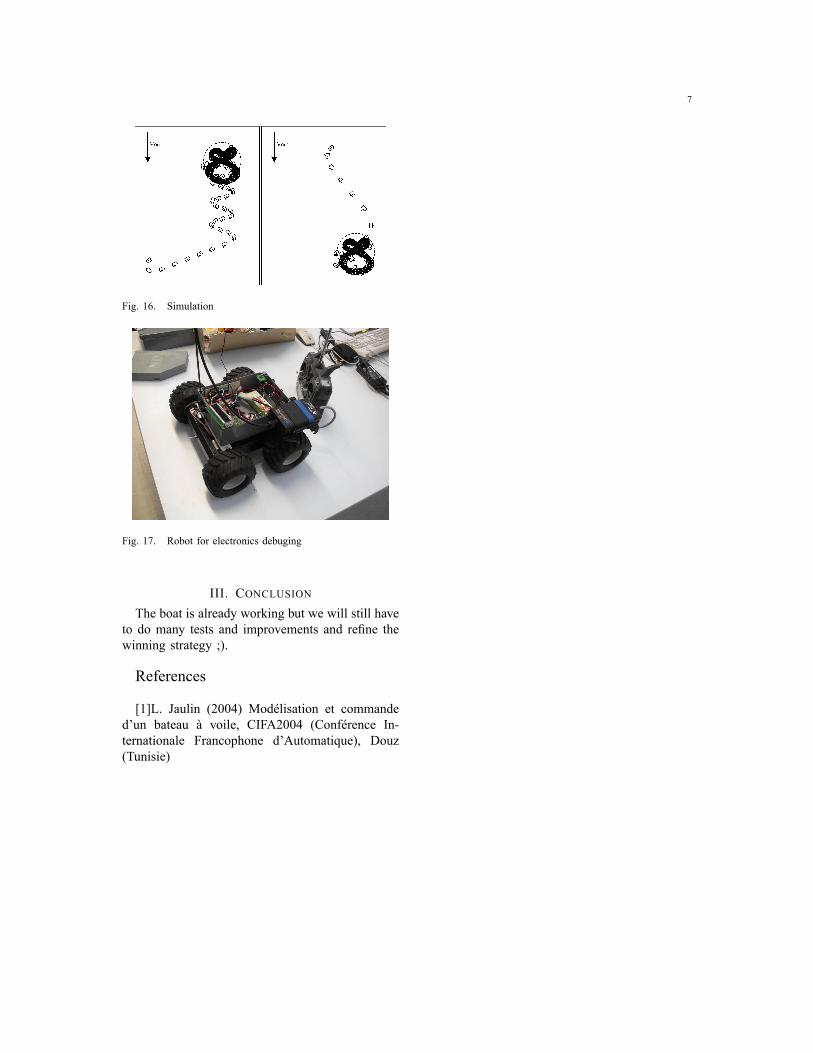
Some results of the SCILAB simulatorare displayed on �gure 16. The scilab �lecan be found on the following addresshttp://www.ensieta.fr/sliwka inthe MicroTransat section.
D. Real tests and debuggingIn order to be able to develop the electronics
at the same time as boat construction, we decidedto test the electronics and the different algorithmsusing a robotic car as shown in �gure 17.
7
Fig. 16. Simulation
Fig. 17. Robot for electronics debuging
III. CONCLUSIONThe boat is already working but we will still have
to do many tests and improvements and re�ne thewinning strategy ;).
References
[1]L. Jaulin (2004) Modélisation et commanded'un bateau à voile, CIFA2004 (Conférence In-ternationale Francophone d'Automatique), Douz(Tunisie)