Autonomous Maritime Landings for Low-cost VTOL Aerial...
8
Autonomous Maritime Landings for Low-cost VTOL Aerial Vehicles Kevin Ling, Derek Chow, Arun Das, and Steven L. Waslander Department of Mechanical and Mechatronics Engineering University of Waterloo, Waterloo, Canada {kling, d8chow, arun.das, stevenw}@uwaterloo.ca Abstract—Autonomous landing of quadrotor UAV on a maritime vessel is a challenging task, as low cost sensors, unknown movements of the landing surface, and external disturbances make it difficult to generate a relative pose estimate with sufficient accuracy for landing. In this work, we propose an architecture that avoids sensor limitations while allowing for accurate relative pose estimation, even in the presence of wind disturbances. The final landing sequence is performed entirely in the body-fixed inertial frame so that noisy measurements from the GPS and magnetometer sensors do not degrade the relative estimation accuracy. Simulation results of the entire system architecture are presented, as well as experimental results of visual landing pad tracking for representative motions, which demonstrate the validity of the approach. Keywords-Mobile robotics, autonomous landing, quadrotor, vision, target-tracking. I. I NTRODUCTION As quadrotor UAVs have become more accessible to commercial, research, and military users, many applications have been pushing the operating limits of the vehicles and using them in increasingly difficult settings. One such setting is that of maritime landings on a ship. Numerous appli- cations exist that require autonomous maritime deployment and retrieval of a UAV, such as iceberg monitoring, coastal surveillance [1], and wildlife monitoring [2]. Autonomous maritime landing of a quadrotor UAV poses many challenges [3], [4]. Low-cost GPS units found on most quadrotor UAVs have errors as high as 5 m CEP. Combined with the GPS errors on the ship, the relative position estimate could be off by as much as 10 m if calculated using GPS alone. Magnetometers on UAVs are subject to a barrage of electrical noise from the motors and computers of the vehicle, resulting in large heading errors which are further aggravated by operation in polar regions. Poor knowledge of the vehicle’s heading prohibits the generation of purposeful control commands required for accurate inertial positioning and landing. The estimation of the ship movement is difficult to predict due to waves, ocean currents, and other disturbances. Low-quality pose measure- ments and a moving landing surface makes autonomous maritime landing a difficult task to perform. Marine surveillance missions inherently require the inclu- sion of a camera on the UAV platform, which can also be used to generate accurate relative pose estimates between This work was supported by the Natural Sciences and Engineering Research Council (NSERC) through the NSERC Canadian Field Robotics Network (NCFRN) and CRDPJ-397768-2010. the UAV and the landing area. The relative positioning error can be further improved through the use of visual targets mounted on the ship deck, which are easily identified and tracked using the camera. We employ an AprilTag fiducial target [5] to provide a 25 Hz relative pose measurement in the critical final landing stage of flight. In this paper, a system architecture to solve the small quadrotor maritime landing problem is presented. The em- phasis of this work is to identify a feasible solution to automated landing using low cost sensors and computers that are already available on the vehicle. The architecture consists of three distinct phases: rendezvous, target acquisition, and landing. Rendezvous requires low relative pose accuracy and can rely on GPS and inertial measurement unit (IMU) data. Once the quadrotor is within range of the target, it will begin searching for the AprilTag fiducial marker. Once found, the position estimation will switch entirely to vision and IMU sensors. At this point, the estimation and control are redefined entirely in the body-fixed inertial (BFI) frame, which eliminates reliance on both GPS or magnetometer data when executing the final critical landing stage. The main contributions of this work are twofold. First, the novel system architecture is defined addressing limitations of low cost sensing and onboard computation. Secondly, a body-fixed inertial coordinate frame is used to define the landing controller avoiding the use of low-quality data during the landing phase. By seeding the integrator effort through the transition between control regimes, the BFI controller is still capable of rejecting wind disturbances without any requirement for state estimates in the inertial frame. Only feedforward terms remain in the inertial frame, which are augmented by BFI integral control terms to eliminate biases in the inertial state estimates. The paper proceeds as follows. Section II surveys re- lated work in autonomous ship landing. We formulate the quadrotor, ship and sensor models in Section III. The system architecture is presented in Section IV, with descriptions of the vision, estimation and control methods employed. Finally, Section V demonstrates simulation results of all stages of the landing process and experimental results of the onboard, vision-only, target tracking. II. RELATED WORK Boeing’s Unmanned Little Bird (ULB) is perhaps the best demonstration of a successful ship landing by a rotary-wing UAV. They have demonstrated over 100 landings on a mov- ing trailer platform and 16 landings on a ship in the ocean
Transcript of Autonomous Maritime Landings for Low-cost VTOL Aerial...
Autonomous Maritime Landings for Low-cost VTOL Aerial Vehicles
Kevin Ling, Derek Chow, Arun Das, and Steven L. WaslanderDepartment of Mechanical and Mechatronics Engineering
University of Waterloo, Waterloo, Canada{kling, d8chow, arun.das, stevenw}@uwaterloo.ca
Abstract—Autonomous landing of quadrotor UAV on amaritime vessel is a challenging task, as low cost sensors,unknown movements of the landing surface, and externaldisturbances make it difficult to generate a relative poseestimate with sufficient accuracy for landing. In this work, wepropose an architecture that avoids sensor limitations whileallowing for accurate relative pose estimation, even in thepresence of wind disturbances. The final landing sequence isperformed entirely in the body-fixed inertial frame so thatnoisy measurements from the GPS and magnetometer sensorsdo not degrade the relative estimation accuracy. Simulationresults of the entire system architecture are presented, as wellas experimental results of visual landing pad tracking forrepresentative motions, which demonstrate the validity of theapproach.
Keywords-Mobile robotics, autonomous landing, quadrotor,vision, target-tracking.
I. INTRODUCTION
As quadrotor UAVs have become more accessible tocommercial, research, and military users, many applicationshave been pushing the operating limits of the vehicles andusing them in increasingly difficult settings. One such settingis that of maritime landings on a ship. Numerous appli-cations exist that require autonomous maritime deploymentand retrieval of a UAV, such as iceberg monitoring, coastalsurveillance [1], and wildlife monitoring [2].
Autonomous maritime landing of a quadrotor UAV posesmany challenges [3], [4]. Low-cost GPS units found onmost quadrotor UAVs have errors as high as 5 m CEP.Combined with the GPS errors on the ship, the relativeposition estimate could be off by as much as 10 m ifcalculated using GPS alone. Magnetometers on UAVs aresubject to a barrage of electrical noise from the motorsand computers of the vehicle, resulting in large headingerrors which are further aggravated by operation in polarregions. Poor knowledge of the vehicle’s heading prohibitsthe generation of purposeful control commands required foraccurate inertial positioning and landing. The estimation ofthe ship movement is difficult to predict due to waves, oceancurrents, and other disturbances. Low-quality pose measure-ments and a moving landing surface makes autonomousmaritime landing a difficult task to perform.
Marine surveillance missions inherently require the inclu-sion of a camera on the UAV platform, which can also beused to generate accurate relative pose estimates between
This work was supported by the Natural Sciences and EngineeringResearch Council (NSERC) through the NSERC Canadian Field RoboticsNetwork (NCFRN) and CRDPJ-397768-2010.
the UAV and the landing area. The relative positioning errorcan be further improved through the use of visual targetsmounted on the ship deck, which are easily identified andtracked using the camera. We employ an AprilTag fiducialtarget [5] to provide a 25 Hz relative pose measurement inthe critical final landing stage of flight.
In this paper, a system architecture to solve the smallquadrotor maritime landing problem is presented. The em-phasis of this work is to identify a feasible solution toautomated landing using low cost sensors and computers thatare already available on the vehicle. The architecture consistsof three distinct phases: rendezvous, target acquisition, andlanding. Rendezvous requires low relative pose accuracyand can rely on GPS and inertial measurement unit (IMU)data. Once the quadrotor is within range of the target, itwill begin searching for the AprilTag fiducial marker. Oncefound, the position estimation will switch entirely to visionand IMU sensors. At this point, the estimation and controlare redefined entirely in the body-fixed inertial (BFI) frame,which eliminates reliance on both GPS or magnetometerdata when executing the final critical landing stage.
The main contributions of this work are twofold. First, thenovel system architecture is defined addressing limitationsof low cost sensing and onboard computation. Secondly,a body-fixed inertial coordinate frame is used to definethe landing controller avoiding the use of low-quality dataduring the landing phase. By seeding the integrator effortthrough the transition between control regimes, the BFIcontroller is still capable of rejecting wind disturbanceswithout any requirement for state estimates in the inertialframe. Only feedforward terms remain in the inertial frame,which are augmented by BFI integral control terms toeliminate biases in the inertial state estimates.
The paper proceeds as follows. Section II surveys re-lated work in autonomous ship landing. We formulate thequadrotor, ship and sensor models in Section III. The systemarchitecture is presented in Section IV, with descriptionsof the vision, estimation and control methods employed.Finally, Section V demonstrates simulation results of allstages of the landing process and experimental results ofthe onboard, vision-only, target tracking.
II. RELATED WORK
Boeing’s Unmanned Little Bird (ULB) is perhaps the bestdemonstration of a successful ship landing by a rotary-wingUAV. They have demonstrated over 100 landings on a mov-ing trailer platform and 16 landings on a ship in the ocean
[6]. The system relies on high accuracy relative position andinertial orientation measurements from a NovAtel RTK GPSwith an integrated IMU, a radar altimeter, and a ship fittedwith a Landing Period Designator (LPD). Additionally, agrate and anchor system was implemented to ensure that thehelicopter would latch onto the landing pad and eliminate therisk of tipover. Although effective, the solution exceeds thepayload capacity and intended cost of the small UAVs underconsideration. Furthermore, the requirement for an LPD andspecialized landing grate are constricting as it limits theships a UAV can land on.
Shakernia et al. propose a vision based approach ex-tending the ego motion problem of tracking features in anunstructured environment [7]. The authors extended existingcamera pose estimation algorithms to work with coplanarpoints located on the landing pad. Saripalli et al. demon-strated successful landings on a target helipad using visionto augment the position estimates from DGPS [8]. Theauthors also present an image processing scheme to extractthe position of the target helipad from a binary image, ahigh level state machine to drive the helicopter functions,and a behaviour based control scheme used to detect thelanding target and maintain stability. They do not, however,consider the effects of wind in the inertial frame, and rely ona precise vehicle model for nonlinear control. A more recentwork by Tribou et al. proposes a method through whicha quadrotor could follow an arbitrary relative trajectorythrough position based servoing by tracking features onan object. Again, a precise vehicle model is required forthe feedback linearizing controller, and the method was notdemonstrated experimentally [9].
Garratt et al. take a different approach and tackle the issueof estimating deck attitude on a ship. In their work, they lookat landing an autonomous helicopter on a large ship usinga narrowband light beacon on the ship and a custom madelidar which scans a circle on the ship’s deck [10]. The lightbeacon is detected by an optical camera on the helicopter andprovides a bearing to the landing platform. The lidar, whichforms their deck attitude sensing system (DASS), determinesthe relative orientation and range of the ship deck. TheDASS performed very well in their experiments, howeverthe added bulk of a custom lidar would be restricting giventhe payload constraints of common quadrotors.
Finally, Venugopalan et al. present a solution to au-tonomously land an AR Drone Parrot on a kayak [3]. Theauthors approached the problem by using the hover modeof the vehicle to stabilize the vehicle against disturbances.Images captured by a downward facing camera on the Parrotwere streamed to an offboard computer to calculate therelative position of the landing pad and send the appropriatecommands to close the gap between the quadrotor andkayak. Also presented is a novel manoeuvre where thequadrotor rolls and pitches on the spot in order to searchbeyond the camera’s field of view. Although the authors
successfully demonstrate autonomous landing using a lowcost vehicle, the approach is limited by requiring offboardcomputation and is demonstrated only in benign conditionsdue to the limited flight envelope of the vehicle employed.
III. SYSTEM MODELLING
A. Coordinate Conventions
Five main coordinate frames are required in this work.The inertial or east-north-up (ENU) frame, denoted E, isthe basis for GPS measurements and absolute positioning.East, north, and up will also be referred to as the inertial x,y, and z, respectively. The quadrotor body frame Q, with thexQ-axis between rotors 1 and 2 emanating from the centerof gravity (CG), yQ between rotors 2 and 3 and zQ upward,is used to define vehicle motion and forces when convenient.A camera frame is defined at the optic center of the camerawith zC axis perpendicular to the image plane. The body-fixed inertial (BFI) frame is defined as a coordinate framefixed to the centre of rotation of the quadrotor and rotatedto the same yaw as the quadrotor. The horizontal plane ofthe BFI frame is coplanar with the horizontal plane of theinertial frame, E. Finally, a target or model frame, M , isdefined as the body frame of the ship with xM pointing tostarboard, yM to the fore and zM up.
Let RBA ∈ SO(3) represent the rotation matrix whichrotates a point in frame A into frame B. Let PBA representthe position of the origin in frame B with respect to frame A.The generalized transformation between frame A and frameB, TBA , can be expressed as
TBA =
[RBA PBA0 1
]. (1)
The coordinate frames and the transformations between themare presented in Figure 1.
Since most of this paper focuses on translation in theinertial or BFI frame x-y plane, an overbar is used to denotethe horizontal component of a vector R3. For instance,
PE = [xE , yE , zE ]T PE = [xE , yE ]T .
Rotations in R2 about the yaw-axis alone will also bedenoted with an overbar,
Rψ =
[cosψ sinψ− sinψ cosψ
].
B. Quadrotor Dynamics
The quadrotor dynamic models used in this work are wellestablished [11], [12], and rely on mixed-frame rigid bodydynamic equations for translation and rotation. The quadro-tor inertial position is denoted PE = [xE , yE , zE ]T ∈ R3
and body rotation rate is ωQ = [p, q, r]T ∈ R3, so that theequations of motion are
mPE = FE +DE (2)JωQ + ωQ × JωQ = MQ +DQ, (3)
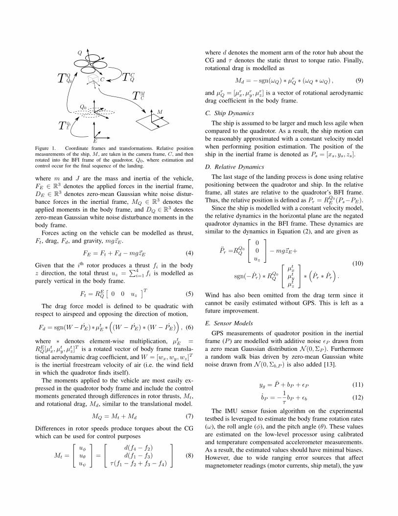
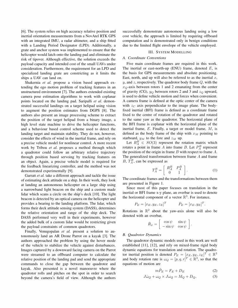
Figure 1. Coordinate frames and transformations. Relative positionmeasurements of the ship, M , are taken in the camera frame, C, and thenrotated into the BFI frame of the quadrotor, Q0, where estimation andcontrol occur for the final sequence of the landing.
where m and J are the mass and inertia of the vehicle,FE ∈ R3 denotes the applied forces in the inertial frame,DE ∈ R3 denotes zero-mean Gaussian white noise distur-bance forces in the inertial frame, MQ ∈ R3 denotes theapplied moments in the body frame, and DQ ∈ R3 denoteszero-mean Gaussian white noise disturbance moments in thebody frame.
Forces acting on the vehicle can be modelled as thrust,Ft, drag, Fd, and gravity, mg~zE .
FE = Ft + Fd −mg~zE (4)
Given that the ith rotor produces a thrust fi in the bodyz direction, the total thrust uz =
∑4i=1 fi is modelled as
purely vertical in the body frame.
Ft = REQ[
0 0 uz]T
(5)
The drag force model is defined to be quadratic withrespect to airspeed and opposing the direction of motion,
Fd = sgn(W − PE)∗µtE ∗(
(W − PE) ∗ (W − PE)), (6)
where ∗ denotes element-wise multiplication, µtE =REQ[µtx, µ
ty, µ
tz]T is a rotated vector of body frame transla-
tional aerodynamic drag coefficient, and W = [wx, wy, wz]T
is the inertial freestream velocity of air (i.e. the wind fieldin which the quadrotor finds itself).
The moments applied to the vehicle are most easily ex-pressed in the quadrotor body frame and include the controlmoments generated through differences in rotor thrusts, Mt,and rotational drag, Md, similar to the translational model.
MQ = Mt +Md (7)
Differences in rotor speeds produce torques about the CGwhich can be used for control purposes
Mt =
uφuθuψ
=
d(f4 − f2)d(f1 − f3)
τ(f1 − f2 + f3 − f4)
(8)
where d denotes the moment arm of the rotor hub about theCG and τ denotes the static thrust to torque ratio. Finally,rotational drag is modelled as
Md = − sgn(ωQ) ∗ µrQ ∗ (ωQ ∗ ωQ) , (9)
and µrQ = [µrx, µry, µ
rz] is a vector of rotational aerodynamic
drag coefficient in the body frame.
C. Ship Dynamics
The ship is assumed to be larger and much less agile whencompared to the quadrotor. As a result, the ship motion canbe reasonably approximated with a constant velocity modelwhen performing position estimation. The position of theship in the inertial frame is denoted as Ps = [xs, ys, zs].
D. Relative Dynamics
The last stage of the landing process is done using relativepositioning between the quadrotor and ship. In the relativeframe, all states are relative to the quadrotor’s BFI frame.Thus, the relative position is defined as Pr = RQ0
E (Ps−PE).Since the ship is modelled with a constant velocity model,
the relative dynamics in the horizontal plane are the negatedquadrotor dynamics in the BFI frame. These dynamics aresimilar to the dynamics in Equation (2), and are given as
Pr =RQ0
Q
00uz
−mg~zE+
sgn(−Pr) ∗RQ0
Q
µtxµtyµtz
∗ (Pr ∗ Pr) .(10)
Wind has also been omitted from the drag term since itcannot be easily estimated without GPS. This is left as afuture improvement.
E. Sensor Models
GPS measurements of quadrotor position in the inertialframe (P ) are modelled with additive noise εP drawn froma zero mean Gaussian distribution N (0,ΣP ). Furthermorea random walk bias driven by zero-mean Gaussian whitenoise drawn from N (0,Σb,P ) is also added [13].
yg = P + bP + εP (11)
bP = −1
τbP + εb (12)
The IMU sensor fusion algorithm on the experimentaltestbed is leveraged to estimate the body frame rotation rates(ω), the roll angle (φ), and the pitch angle (θ). These valuesare estimated on the low-level processor using calibratedand temperature compensated accelerometer measurements.As a result, the estimated values should have minimal biases.However, due to wide ranging error sources that affectmagnetometer readings (motor currents, ship metal), the yaw
estimate of the vehicle (ψ) may be significantly corrupted inflight. These heading bias errors are modelled by the samerandom walk used to describe GPS biases. The model forIMU sensors is then given as
yi =
ψθφωQ
+
bψ + εψεθεφεω
, (13)
where each noise source ε∗ is drawn from N (0,Σ∗). Thesimulated AprilTag detection system provides bias free rela-tive pose estimates with additive zero-mean Gaussian whitenoise, as follows,
yt =
Prψtθtφt
+
εPεψεθεφ
. (14)
F. Target Detection
The AprilTag visual fiducial system was used to measurethe relative pose of the landing area on the ship deck.This visual fiducial system was chosen over lighter-weightalternatives for several reasons: it provides a 6-DOF poseestimate, the detection range scales with the tag size, and itgenerates few false positives.
A C++ implementation of the AprilTag system was used[14] with some modifications in order to increase the speedof AprilTag detection, so that a reasonable measurement ratecould be achieved onboard the quadrotor. The quadrilateraldetection algorithm was replaced with a simpler Canny edgedetector and the approxPolyDP function from OpenCV.
Using a uEye UI-1221LE camera with an attached wideangle lens, images are captured with a field of view of about60◦ and a 752 × 480 resolution. After resizing the imagesto 376 × 240, a detection rate of 20-25 frames/second wasachieved on the Asctec Pelican Intel Atom board for the16h5 AprilTag set. At this resolution, a 15 cm x 15 cmmarker can be detected at a range of up to 5 m.
The AprilTag detection algorithm returns the relative poseof the tag in the camera frame TCM . This transformation isconverted into the body frame through the transformationTQ0
Q TQC .
IV. SYSTEM ARCHITECTURE
The proposed maritime landing process consists of threestages: rendezvous, acquiring the AprilTag, and descendingwith relative positioning. The three stages are illustrated inFigure 2. First, the quadrotor flies at a constant velocity toa rendezvous point. Then in the second stage the quadrotorsearches for the AprilTag on the ship. Once the AprilTaghas been acquired, position control and estimation changesfrom the world frame to the BFI frame and the final stagebegins. The AprilTag detections provide measurements for
A B
C
Figure 2. The three stages of flight for the maritime landing. In the firststage, the quadrotor approaches the ship on a rendezvous trajectory. In thesecond segment, the quadrotor acquires the AprilTag on the ship. Thenin the final stage, the quadrotor descends to the ship while tracking theAprilTag.
the position of the ship relative to the quadrotor. Whenthe relative position error is below a certain threshold, thequadrotor begins descend to the ship deck.
The three stages of the flight are performed with differentposition controllers, which are described in the followingsubsections. The experimental attitude control to achievethe desired roll and pitch is handled by a closed-sourcecontroller on the low-level processor of the testbed vehicle.The altitude control and simulation attitude control areimplemented as described by Hoffmann et al. [11].
In all stages of flight, the following nonlinear inversion,derived from the dynamic model, is applied to obtain thecommanded angles [12].
φd = sin−1
(muyuz
)(15)
θd = − sin−1
(mux
uz cos(φd)
), (16)
The desired horizontal accelerations in the BFI frame, uxand uy , are thereby mapped to commanded roll and pitchangles, φd and θd, respectively.
A feedforward command is also applied in all stages offlight. The feedforward term is calculated with
uf =sgn(vd) ∗ µtE ∗ (vd ∗ vd)
m(17)
where vd ∈ R2 is the desired horizontal velocity in theinertial frame and uf = [uf,x, uf,y]T is the feedforwardacceleration vector. This relation is obtained by finding theacceleration required to balance out the drag force definedin Equation (6) at the desired velocity.
A. Rendezvous
When the autonomous landing sequence is initiated, thecurrent estimated positions of both vehicles and the currentestimated velocity of the boat are used to calculate arendezvous point. Two similar triangles are constructed; onewith the positions of the quadrotor, ship, and rendezvous
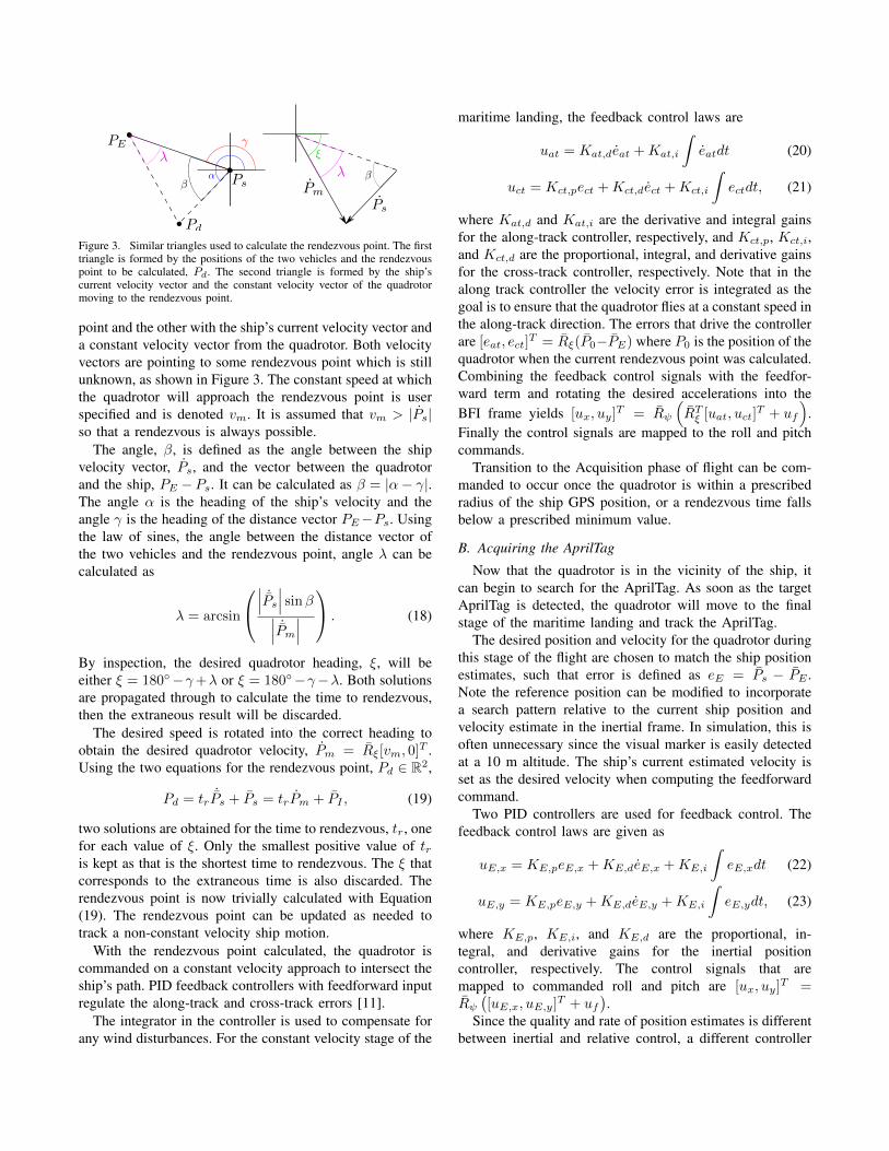
Figure 3. Similar triangles used to calculate the rendezvous point. The firsttriangle is formed by the positions of the two vehicles and the rendezvouspoint to be calculated, Pd. The second triangle is formed by the ship’scurrent velocity vector and the constant velocity vector of the quadrotormoving to the rendezvous point.
point and the other with the ship’s current velocity vector anda constant velocity vector from the quadrotor. Both velocityvectors are pointing to some rendezvous point which is stillunknown, as shown in Figure 3. The constant speed at whichthe quadrotor will approach the rendezvous point is userspecified and is denoted vm. It is assumed that vm > |Ps|so that a rendezvous is always possible.
The angle, β, is defined as the angle between the shipvelocity vector, Ps, and the vector between the quadrotorand the ship, PE −Ps. It can be calculated as β = |α− γ|.The angle α is the heading of the ship’s velocity and theangle γ is the heading of the distance vector PE−Ps. Usingthe law of sines, the angle between the distance vector ofthe two vehicles and the rendezvous point, angle λ can becalculated as
λ = arcsin
∣∣∣ ˙Ps
∣∣∣ sinβ∣∣∣ ˙Pm
∣∣∣ . (18)
By inspection, the desired quadrotor heading, ξ, will beeither ξ = 180◦−γ+λ or ξ = 180◦−γ−λ. Both solutionsare propagated through to calculate the time to rendezvous,then the extraneous result will be discarded.
The desired speed is rotated into the correct heading toobtain the desired quadrotor velocity, Pm = Rξ[vm, 0]T .Using the two equations for the rendezvous point, Pd ∈ R2,
Pd = tr˙Ps + Ps = trPm + PI , (19)
two solutions are obtained for the time to rendezvous, tr, onefor each value of ξ. Only the smallest positive value of tris kept as that is the shortest time to rendezvous. The ξ thatcorresponds to the extraneous time is also discarded. Therendezvous point is now trivially calculated with Equation(19). The rendezvous point can be updated as needed totrack a non-constant velocity ship motion.
With the rendezvous point calculated, the quadrotor iscommanded on a constant velocity approach to intersect theship’s path. PID feedback controllers with feedforward inputregulate the along-track and cross-track errors [11].
The integrator in the controller is used to compensate forany wind disturbances. For the constant velocity stage of the
maritime landing, the feedback control laws are
uat = Kat,deat +Kat,i
∫eatdt (20)
uct = Kct,pect +Kct,dect +Kct,i
∫ectdt, (21)
where Kat,d and Kat,i are the derivative and integral gainsfor the along-track controller, respectively, and Kct,p, Kct,i,and Kct,d are the proportional, integral, and derivative gainsfor the cross-track controller, respectively. Note that in thealong track controller the velocity error is integrated as thegoal is to ensure that the quadrotor flies at a constant speed inthe along-track direction. The errors that drive the controllerare [eat, ect]
T = Rξ(P0−PE) where P0 is the position of thequadrotor when the current rendezvous point was calculated.Combining the feedback control signals with the feedfor-ward term and rotating the desired accelerations into theBFI frame yields [ux, uy]T = Rψ
(RTξ [uat, uct]
T + uf
).
Finally the control signals are mapped to the roll and pitchcommands.
Transition to the Acquisition phase of flight can be com-manded to occur once the quadrotor is within a prescribedradius of the ship GPS position, or a rendezvous time fallsbelow a prescribed minimum value.
B. Acquiring the AprilTag
Now that the quadrotor is in the vicinity of the ship, itcan begin to search for the AprilTag. As soon as the targetAprilTag is detected, the quadrotor will move to the finalstage of the maritime landing and track the AprilTag.
The desired position and velocity for the quadrotor duringthis stage of the flight are chosen to match the ship positionestimates, such that error is defined as eE = Ps − PE .Note the reference position can be modified to incorporatea search pattern relative to the current ship position andvelocity estimate in the inertial frame. In simulation, this isoften unnecessary since the visual marker is easily detectedat a 10 m altitude. The ship’s current estimated velocity isset as the desired velocity when computing the feedforwardcommand.
Two PID controllers are used for feedback control. Thefeedback control laws are given as
uE,x = KE,peE,x +KE,deE,x +KE,i
∫eE,xdt (22)
uE,y = KE,peE,y +KE,deE,y +KE,i
∫eE,ydt, (23)
where KE,p, KE,i, and KE,d are the proportional, in-tegral, and derivative gains for the inertial positioncontroller, respectively. The control signals that aremapped to commanded roll and pitch are [ux, uy]T =Rψ([uE,x, uE,y]T + uf
).
Since the quality and rate of position estimates is differentbetween inertial and relative control, a different controller
gains is selected for each control mode. The relative positionestimates driven by vision will be more accurate than theinertial estimates from GPS, so higher gains will be used toimprove tracking performance in the relative case.
C. Relative Position Tracking
Relative position estimation is done entirely in the BFIframe. AprilTag detections, transformed into the BFI frame,provide the measurement updates for the estimator. Upon thefirst AprilTag detection, the relative position estimator willinitialize its position states to the new visual measurements.The velocity states in the estimator will be initialized toPr = RQ0
E (Ps − PE), using the current inertial estimates.Any large error in the velocity initialization will be correctedquickly if visual measurements continue to be received. Thequadrotor’s estimated roll, pitch, and collective thrust areused as inputs to propagate the states of the estimator.
The estimated states of the relative estimator are x =[Pr
˙Pr]T and the state prediction equation is
x =
R∆ψ˙Pr
−2(ψ × Pr
)+ ¨Pr
. (24)
At each time step, ∆ψ is obtained by integrating the z-axis gyroscope. As part of the prediction step, the states arerotated by ∆ψ. While integrating gyroscopes for a prolongedperiod will result in significant drift, the estimator relies onthe AprilTag measurements to correct any drift that mayoccur. Thus relative position tracking is abandoned whenAprilTag measurements have not been received for a shortperiod of time due to occlusion. If the quadrotor cannotregain sight of the AprilTag within the time limit, the systemreverts to the acquisition phase until the next AprilTagdetection occurs.
Similar to the acquisition phase of flight, the feedbackcontrol laws are
ur,x = Kr,per,x +Kr,der,x +Kr,i
∫er,xdt (25)
ur,y = Kr,per,y +Kr,der,y +Kr,i
∫er,ydt, (26)
where Kr,p, Kr,i, and Kr,d are the proportional, inte-gral, and derivative gains for the inertial position con-troller, respectively. However, the control signals that aremapped to commanded roll and pitch are now [ux, uy]T =[uI,x, uI,y]T + Rψuf . The major difference is that thefeedback control signals are no longer rotated. This elim-inates possible corruption from a biased yaw estimate. GPSmeasurements are only used in the feedforward term of thecontrol law. As a result, the main sources of positioningerror have been eliminated from the feedback loop.
The prediction step in the relative position estimation isdependant on wind, as the airspeed directly affects the dragterm. A wind estimation scheme is beyond the scope of
this paper, so it is expected that the estimation performancemay degrade in extreme wind conditions. Adding wind stateestimation, such as presented by Waslander and Wang [15],is left as an area of future work.
D. Controller Switching
The transition between inertial and relative control issmoothed by seeding the controller integrators with thevalues of the previous stage. While flying in either inertialcontrol or relative control mode, properly tuned integratorsshould wind up to cancel the effects of wind. Rotating thecontroller integrators from the inertial to relative frame, andvice versa, provides a good starting estimate of the controleffort required to overcome wind. This initial seeding ofthe controllers will incorporate both GPS and magnetometererrors, however the initial integrator values will be closer towhat is needed to compensate for wind than if the integratorswere reset when switching controllers. Consequently errorsdue to wind should correct more quickly.
In the rendezvous and AprilTag acquisition stages, po-sition control integrators are tracked in the inertial frame.Moving to relative control, the integrators are rotated into theBFI frame [Ir,x, Ir,y]T = Rφ[IE,x, IE,y]T . Ir,x and Ir,y arethe x and y error integrators in the BFI frame, respectively,and IE,x and IE,y are the x and y error integrators in theinertial frame, respectively.
It is also guaranteed that the controllers will not switchrapidly since the relative position estimator always attemptsto propagate the relative states and regain sight of theAprilTag before switching back to inertial control.
V. RESULTS
A. Simulation Results
All three segments of the maritime landing approachwere simulated in MATLAB. The simulations validate therendezvous trajectory planning and the performance of therelative position estimator in wind. The quadrotor begins ona constant velocity trajectory to rendezvous with the ship.With the quadrotor at an altitude of 10 m, a tag on the shipquickly falls within the quadrotor’s view. Flying a searchpattern for the AprilTag is often unnecessary. For the flightshown, the AprilTag acquisition stage lasted 4.4 seconds.
Wind was simulated by applying a fixed base wind vectorof [3,−4, 0.2]T metres/second and adding wind gusts on top.The wind gusts were generated using the Dryden wind gustmodel [15].
The controller gains used in simulation were:[Kat,i,Kat,d] = [0.04, 0.3], [Kct,p,Kct,i,Kct,d] =[0.2, 0.04, 0.4], [KE,p,KE,i,KE,d] = [0.2, 0.15, 0.85], and[KE,p,KE,i,KE,d] = [0.6, 0.3, 0.85]. GPS updates arereceived at 10 Hz, so inertial control is also performedat that rate. When visual relative position measurementsare received, the control rate switches to 20 Hz to takeadvantage of the better position information. Gaussian
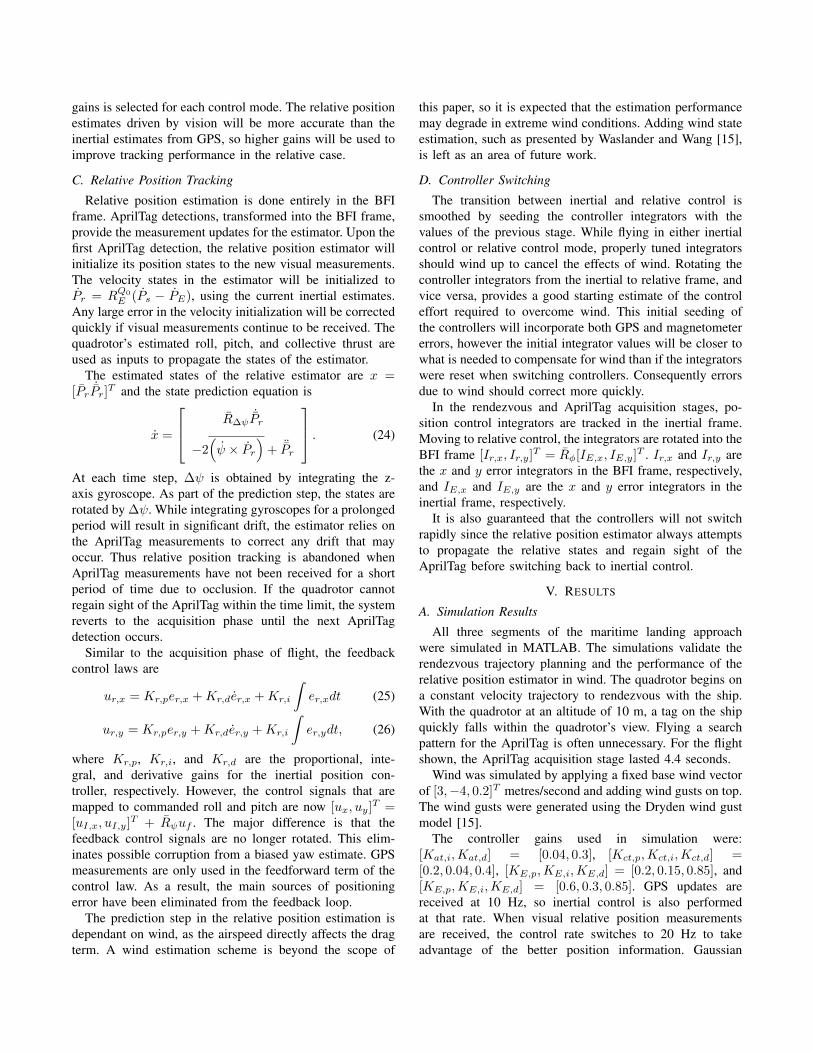
RMS Errors
Rendezvous Along Track (m/s) 1.1521Cross Track (m) 1.1845
AprilTag Acquisition X-Position (m) 1.1734Y-Position (m) 2.9955
Relative Tracking X-Position (m) 0.3382Y-Position (m) 0.7320
Quadrotor GPS X-Position (m) 2.4769Y-Position (m) 2.0442
Magnetometer Yaw (◦) 6.8675
Table IRMS ERRORS IN SIMULATION FOR THE THREE STAGES OF FLIGHT,
GPS MEASUREMENTS, AND MAGNETOMETER MEASUREMENTS.
Figure 4. Simulated quadrotor and ship positions with the quadrotororientation overlaid on top of its position.
noise with a standard deviation of 3 cm is applied torelative position measurements. Mild disturbances are alsoapplied to the translational and rotational dynamics of thequadrotor. The ship follows an arbitrary arc trajectory, tosimulate unpredictable ship motion. GPS noise is tuned tobe a gradual random walk to a maximum of about 5 merror.
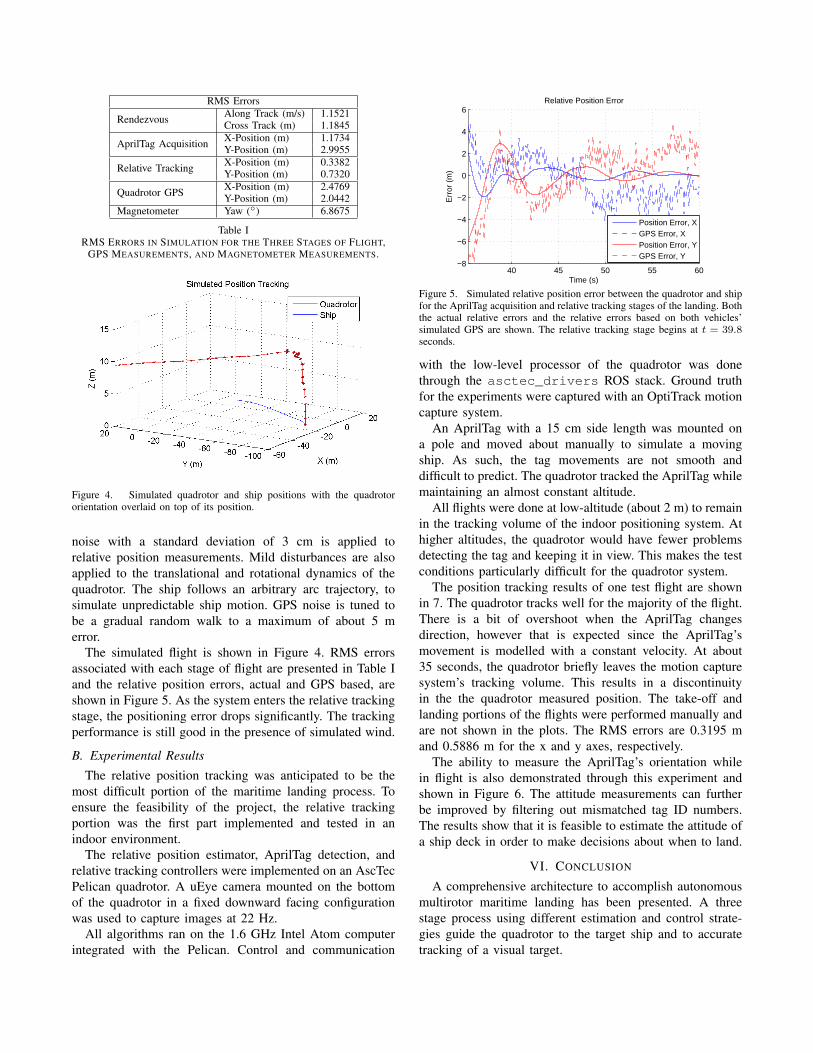
The simulated flight is shown in Figure 4. RMS errorsassociated with each stage of flight are presented in Table Iand the relative position errors, actual and GPS based, areshown in Figure 5. As the system enters the relative trackingstage, the positioning error drops significantly. The trackingperformance is still good in the presence of simulated wind.
B. Experimental Results
The relative position tracking was anticipated to be themost difficult portion of the maritime landing process. Toensure the feasibility of the project, the relative trackingportion was the first part implemented and tested in anindoor environment.
The relative position estimator, AprilTag detection, andrelative tracking controllers were implemented on an AscTecPelican quadrotor. A uEye camera mounted on the bottomof the quadrotor in a fixed downward facing configurationwas used to capture images at 22 Hz.
All algorithms ran on the 1.6 GHz Intel Atom computerintegrated with the Pelican. Control and communication
40 45 50 55 60−8
−6
−4
−2
0
2
4
6Relative Position Error
Time (s)
Err
or (
m)
Position Error, XGPS Error, XPosition Error, YGPS Error, Y
Figure 5. Simulated relative position error between the quadrotor and shipfor the AprilTag acquisition and relative tracking stages of the landing. Boththe actual relative errors and the relative errors based on both vehicles’simulated GPS are shown. The relative tracking stage begins at t = 39.8seconds.
with the low-level processor of the quadrotor was donethrough the asctec_drivers ROS stack. Ground truthfor the experiments were captured with an OptiTrack motioncapture system.
An AprilTag with a 15 cm side length was mounted ona pole and moved about manually to simulate a movingship. As such, the tag movements are not smooth anddifficult to predict. The quadrotor tracked the AprilTag whilemaintaining an almost constant altitude.
All flights were done at low-altitude (about 2 m) to remainin the tracking volume of the indoor positioning system. Athigher altitudes, the quadrotor would have fewer problemsdetecting the tag and keeping it in view. This makes the testconditions particularly difficult for the quadrotor system.
The position tracking results of one test flight are shownin 7. The quadrotor tracks well for the majority of the flight.There is a bit of overshoot when the AprilTag changesdirection, however that is expected since the AprilTag’smovement is modelled with a constant velocity. At about35 seconds, the quadrotor briefly leaves the motion capturesystem’s tracking volume. This results in a discontinuityin the the quadrotor measured position. The take-off andlanding portions of the flights were performed manually andare not shown in the plots. The RMS errors are 0.3195 mand 0.5886 m for the x and y axes, respectively.
The ability to measure the AprilTag’s orientation whilein flight is also demonstrated through this experiment andshown in Figure 6. The attitude measurements can furtherbe improved by filtering out mismatched tag ID numbers.The results show that it is feasible to estimate the attitude ofa ship deck in order to make decisions about when to land.
VI. CONCLUSION
A comprehensive architecture to accomplish autonomousmultirotor maritime landing has been presented. A threestage process using different estimation and control strate-gies guide the quadrotor to the target ship and to accuratetracking of a visual target.
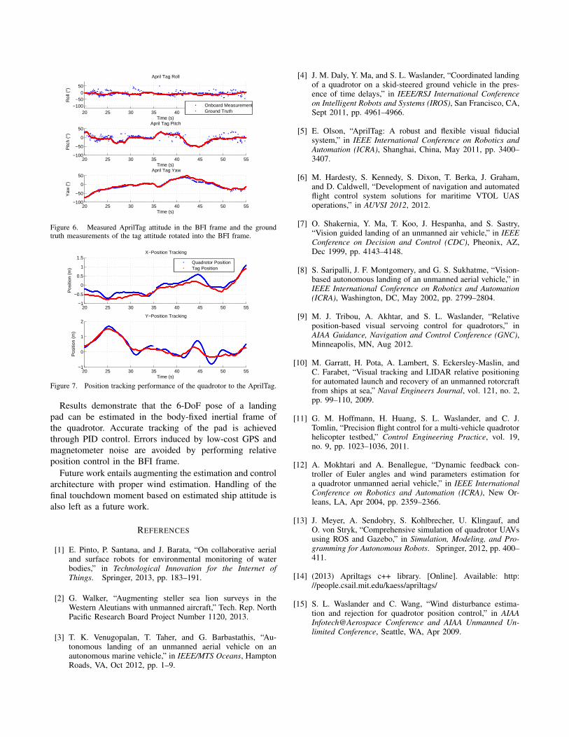
20 25 30 35 40 45 50 55−100
−500
50
Rol
l (°)
Time (s)
April Tag Roll
Onboard MeasurementGround Truth
20 25 30 35 40 45 50 55−100
−50
0
50
Pitc
h (°
)
Time (s)
April Tag Pitch
20 25 30 35 40 45 50 55−100
−50
0
50
Yaw
(°)
Time (s)
April Tag Yaw
Figure 6. Measured AprilTag attitude in the BFI frame and the groundtruth measurements of the tag attitude rotated into the BFI frame.
20 25 30 35 40 45 50 55−1
−0.5
0
0.5
1
1.5
Pos
ition
(m
)
X−Position Tracking
Quadrotor PositionTag Position
20 25 30 35 40 45 50 55−1
0
1
2Y−Position Tracking
Pos
ition
(m
)
Time (s)
Figure 7. Position tracking performance of the quadrotor to the AprilTag.
Results demonstrate that the 6-DoF pose of a landingpad can be estimated in the body-fixed inertial frame ofthe quadrotor. Accurate tracking of the pad is achievedthrough PID control. Errors induced by low-cost GPS andmagnetometer noise are avoided by performing relativeposition control in the BFI frame.
Future work entails augmenting the estimation and controlarchitecture with proper wind estimation. Handling of thefinal touchdown moment based on estimated ship attitude isalso left as a future work.
REFERENCES
[1] E. Pinto, P. Santana, and J. Barata, “On collaborative aerialand surface robots for environmental monitoring of waterbodies,” in Technological Innovation for the Internet ofThings. Springer, 2013, pp. 183–191.
[2] G. Walker, “Augmenting steller sea lion surveys in theWestern Aleutians with unmanned aircraft,” Tech. Rep. NorthPacific Research Board Project Number 1120, 2013.
[3] T. K. Venugopalan, T. Taher, and G. Barbastathis, “Au-tonomous landing of an unmanned aerial vehicle on anautonomous marine vehicle,” in IEEE/MTS Oceans, HamptonRoads, VA, Oct 2012, pp. 1–9.
[4] J. M. Daly, Y. Ma, and S. L. Waslander, “Coordinated landingof a quadrotor on a skid-steered ground vehicle in the pres-ence of time delays,” in IEEE/RSJ International Conferenceon Intelligent Robots and Systems (IROS), San Francisco, CA,Sept 2011, pp. 4961–4966.
[5] E. Olson, “AprilTag: A robust and flexible visual fiducialsystem,” in IEEE International Conference on Robotics andAutomation (ICRA), Shanghai, China, May 2011, pp. 3400–3407.
[6] M. Hardesty, S. Kennedy, S. Dixon, T. Berka, J. Graham,and D. Caldwell, “Development of navigation and automatedflight control system solutions for maritime VTOL UASoperations,” in AUVSI 2012, 2012.
[7] O. Shakernia, Y. Ma, T. Koo, J. Hespanha, and S. Sastry,“Vision guided landing of an unmanned air vehicle,” in IEEEConference on Decision and Control (CDC), Pheonix, AZ,Dec 1999, pp. 4143–4148.
[8] S. Saripalli, J. F. Montgomery, and G. S. Sukhatme, “Vision-based autonomous landing of an unmanned aerial vehicle,” inIEEE International Conference on Robotics and Automation(ICRA), Washington, DC, May 2002, pp. 2799–2804.
[9] M. J. Tribou, A. Akhtar, and S. L. Waslander, “Relativeposition-based visual servoing control for quadrotors,” inAIAA Guidance, Navigation and Control Conference (GNC),Minneapolis, MN, Aug 2012.
[10] M. Garratt, H. Pota, A. Lambert, S. Eckersley-Maslin, andC. Farabet, “Visual tracking and LIDAR relative positioningfor automated launch and recovery of an unmanned rotorcraftfrom ships at sea,” Naval Engineers Journal, vol. 121, no. 2,pp. 99–110, 2009.
[11] G. M. Hoffmann, H. Huang, S. L. Waslander, and C. J.Tomlin, “Precision flight control for a multi-vehicle quadrotorhelicopter testbed,” Control Engineering Practice, vol. 19,no. 9, pp. 1023–1036, 2011.
[12] A. Mokhtari and A. Benallegue, “Dynamic feedback con-troller of Euler angles and wind parameters estimation fora quadrotor unmanned aerial vehicle,” in IEEE InternationalConference on Robotics and Automation (ICRA), New Or-leans, LA, Apr 2004, pp. 2359–2366.
[13] J. Meyer, A. Sendobry, S. Kohlbrecher, U. Klingauf, andO. von Stryk, “Comprehensive simulation of quadrotor UAVsusing ROS and Gazebo,” in Simulation, Modeling, and Pro-gramming for Autonomous Robots. Springer, 2012, pp. 400–411.
[14] (2013) Apriltags c++ library. [Online]. Available: http://people.csail.mit.edu/kaess/apriltags/
[15] S. L. Waslander and C. Wang, “Wind disturbance estima-tion and rejection for quadrotor position control,” in AIAAInfotech@Aerospace Conference and AIAA Unmanned Un-limited Conference, Seattle, WA, Apr 2009.