Bitcoin, Blockchain, Smart Contracts and Decentralized Autonomous Organizations: The Future
Autonomous Decentralized Shape-Based Navigation forSnake Robots in Dense Environments
Guillaume Sartoretti1, Tianyu Wang2, Gabriel Chuang2, Qingyang Li2, and Howie Choset2
Abstract— In this work, we focus on the autonomous naviga-tion of snake robots in densely-cluttered environments, wherecollisions between the robot and obstacles are frequent, whichcould happen often in disaster scenarios, underground caves,or grassland/forest environments. This work takes the viewthat obstacles are not to be avoided, but rather exploited tosupport and direct the motion of the snake robot. We buildupon a decentralized state-of-the-art compliant controller forserpenoid locomotion, and develop a bi-stable dynamical systemthat relies on inertial feedback to continuously steer the robottoward a desired direction. We experimentally show that thiscontroller allows the robot to autonomously navigate denseenvironments by consistently locomoting along a given, globaldirection of travel in the world, which could be selected by ahuman operator or a higher level planner. We further equipthe robot with an onboard vision system, allowing the robotto autonomously select its own direction of travel, based onthe obstacle distribution ahead of its position (i.e., enactingfeedforward control). In those additional experiments on hard-ware, we show how such an exteroceptive sensor can allow therobot to steer before hitting obstacles and to preemptively avoidchallenging regions where proprioception-only (i.e., torque andinertial) feedback control would not suffice.
I. INTRODUCTION
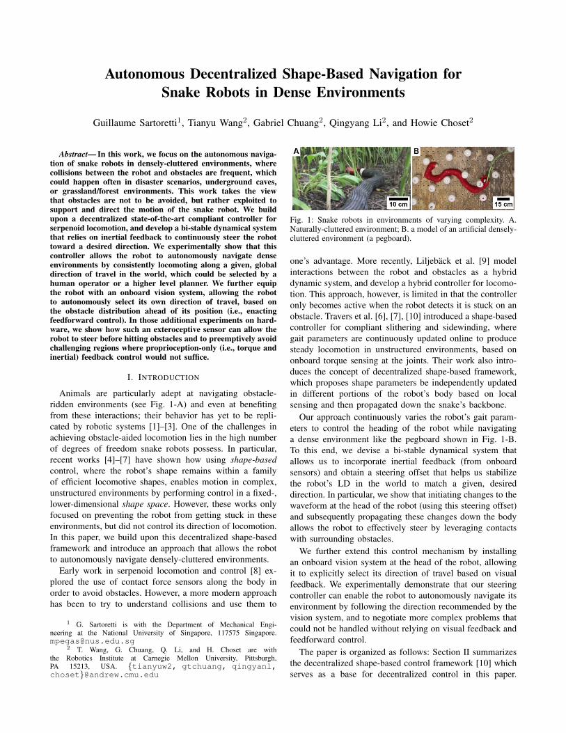
Animals are particularly adept at navigating obstacle-ridden environments (see Fig. 1-A) and even at benefitingfrom these interactions; their behavior has yet to be repli-cated by robotic systems [1]–[3]. One of the challenges inachieving obstacle-aided locomotion lies in the high numberof degrees of freedom snake robots possess. In particular,recent works [4]–[7] have shown how using shape-basedcontrol, where the robot’s shape remains within a familyof efficient locomotive shapes, enables motion in complex,unstructured environments by performing control in a fixed-,lower-dimensional shape space. However, these works onlyfocused on preventing the robot from getting stuck in theseenvironments, but did not control its direction of locomotion.In this paper, we build upon this decentralized shape-basedframework and introduce an approach that allows the robotto autonomously navigate densely-cluttered environments.
Early work in serpenoid locomotion and control [8] ex-plored the use of contact force sensors along the body inorder to avoid obstacles. However, a more modern approachhas been to try to understand collisions and use them to
1 G. Sartoretti is with the Department of Mechanical Engi-neering at the National University of Singapore, 117575 [email protected]
2 T. Wang, G. Chuang, Q. Li, and H. Choset are withthe Robotics Institute at Carnegie Mellon University, Pittsburgh,PA 15213, USA. {tianyuw2, gtchuang, qingyanl,choset}@andrew.cmu.edu
Fig. 1: Snake robots in environments of varying complexity. A.Naturally-cluttered environment; B. a model of an artificial densely-cluttered environment (a pegboard).
one’s advantage. More recently, Liljeback et al. [9] modelinteractions between the robot and obstacles as a hybriddynamic system, and develop a hybrid controller for locomo-tion. This approach, however, is limited in that the controlleronly becomes active when the robot detects it is stuck on anobstacle. Travers et al. [6], [7], [10] introduced a shape-basedcontroller for compliant slithering and sidewinding, wheregait parameters are continuously updated online to producesteady locomotion in unstructured environments, based ononboard torque sensing at the joints. Their work also intro-duces the concept of decentralized shape-based framework,which proposes shape parameters be independently updatedin different portions of the robot’s body based on localsensing and then propagated down the snake’s backbone.
Our approach continuously varies the robot’s gait param-eters to control the heading of the robot while navigatinga dense environment like the pegboard shown in Fig. 1-B.To this end, we devise a bi-stable dynamical system thatallows us to incorporate inertial feedback (from onboardsensors) and obtain a steering offset that helps us stabilizethe robot’s LD in the world to match a given, desireddirection. In particular, we show that initiating changes to thewaveform at the head of the robot (using this steering offset)and subsequently propagating these changes down the bodyallows the robot to effectively steer by leveraging contactswith surrounding obstacles.
We further extend this control mechanism by installingan onboard vision system at the head of the robot, allowingit to explicitly select its direction of travel based on visualfeedback. We experimentally demonstrate that our steeringcontroller can enable the robot to autonomously navigate itsenvironment by following the direction recommended by thevision system, and to negotiate more complex problems thatcould not be handled without relying on visual feedback andfeedforward control.
The paper is organized as follows: Section II summarizesthe decentralized shape-based control framework [10] whichserves as a base for decentralized control in this paper.

Section III introduces our continuous, feedback steeringcontroller. Section IV describes the vision-based controllerused to enable the robot to select its own LD. Section Vexplains our experimental validation of the complete close-loop autonomous navigation framework, composed of theproprioception-only (i.e., torque and inertial feedback) steer-ing controller and the vision-enabled controller. Finally,Section VII presents concluding remarks.
II. BACKGROUND ON DECENTRALIZED SHAPE-BASEDCONTROL FOR LOCOMOTION
This section presents the general framework [10] uponwhich we build to control a snake robot in a decentralizedmanner, by adapting gait parameters in different portions ofthe snake based on local sensing before propagating thesevalues down the snake’s backbone.
A. Serpenoid Curve Overview
We consider an N -jointed snake robot, with state variableθ(t) = (θ1(t), ..., θN (t)) ∈ RN expressing the joint angles1 ≤ i ≤ N at time t. Hirose et al. [8] described a family ofcurves, the serpenoid curves, that can parameterize the shapeof a snake robot during locomotion under a variety of gaits.In this work, we use a gait called planar slithering which isessentially controls the snake robot to assume the shape ofa time-varying serpenoid curve, i.e., [7], [8], [11]:
θi(t) = θ0 +A sin (ωS si − ωT t) , (1)
where θ0 is a constant curvature offset, si is the distancefrom the head of the snake to the joint i along the snake’sbody, A, ωS and ωT respectively are the amplitude, thespatial and temporal frequencies of the serpenoid curve. Thetemporal frequency ωT defines the (temporal) period of theserpenoid gait (T = 2π/ωT ), whereas the spatial frequencyωS determines the number of sinusoidal periods nS alongthe robot’s body (via ωS = 2π nS).
B. Shape Functions for Dimensionality Reduction
Throughout this paper, we consider two controllers for therobot that build upon the decentralized shape-based controlintroduced in [7], [10], which we briefly summarize in thissection. Shape-based control makes use of shape functions,as a natural way to reduce the dimensionality in systemswith high degrees-of-freedom [10]. The goal of such a shapefunction h : Σ→ RN is to determine θ(t) as a function of asmall number of control parameters. Those parameters createa shape space Σ, which is usually of a lower dimension thanRN . In our case, we consider the case where the amplitudeand spatial frequency in Eq.(1) can be dynamically set andtherefore form a two-dimensional shape space. The shapefunction h(A,ωS) of our system is simply the serpenoidcurve Eq.(1), with the two control parameters being theamplitude and spatial frequency, while the other parametersare fixed:
h : Σ = R2 7→ RN
hi(A(t), ωS(t)) = θi(t)
= θ0 +A(t) sin (ωS(t) si − ωT t) .(2)
C. Decentralized Control
More recent works on the shape-based compliant frame-work proposed the idea of decentralizing control, to endowthe robot with local reflexes and better handle situationswhere different portions of the robot would need differentmodifications of the shape parameters [7]. These sub-groupsof joints are usually created based on the current shape of therobot, and propagate down its backbone during locomotion.Specifically, let us define W windows (i.e., groups of joints),in which independent values Aj(t) and ωS,j(t) (1 ≤ j ≤W )are defined for the amplitude and the spatial frequency. Thedecentralized time- and space-dependent control parametersξ(t, s) (ξ = {A,ωS}) are now expressed in a sum-of-sigmoids form:
ξ(t, s) =
W∑j=1
ξj ·(
1
1 + e−m(s−aj(t))+
1
1 + e−m(bj(t)−s)
),
(3)with aj(t), bj(t) respectively the start and end position of thej-th window along the snake’s body, and m ∈ R the slopeof the sigmoid functions.
In this paper, following [7], we also let the windows’position and number be dynamically set based on the currentshape of the robot’s body. The first window encompassesall joints from the robot’s head to the first point of zero-curvature along its body. The following windows are definedbetween two successive points of zero-curvature along therobot’s body, and the last window between the last point ofzero curvature and the tail. We also let the windows naturallymove down the body at the same rate as the serpenoidcurve (i.e., 2π/ωT ). This process enables us to naturally passinformation along the robot’s body, as the snake locomotesthrough its environment.
III. CONTINUOUS STEERING CONTROLLER
For navigation in dense environments, we build upon thedecentralized compliant controller [7], [10] to endow a snakerobot with steady, uninterrupted locomotion in unstructuredenvironments. On top of this controller, we then presenta continuously active controller to keep the snake robot’smotion in a desired direction of travel by relying on onboardinertial sensing.
To this end, we first present a novel method to predictthe current direction of motion from the robot’s currentgait phase and head orientation in the world. Similar to thediscrete case, we show that the head joint is central whenestimating the locomotive direction of the snake, especiallyduring interactions with obstacles. Then, we describe ourdynamical system approach to autonomous steering, whichrelies on the current and desired directions of motion of therobot to continuously steer it.
A. Locomotive Direction Estimation
In dense environments, a snake robot needs to constantlybe correcting it direction of motion, since this directionmay be changed by the many collisions with obstacle therobot experiences. To this end, we first need to estimate
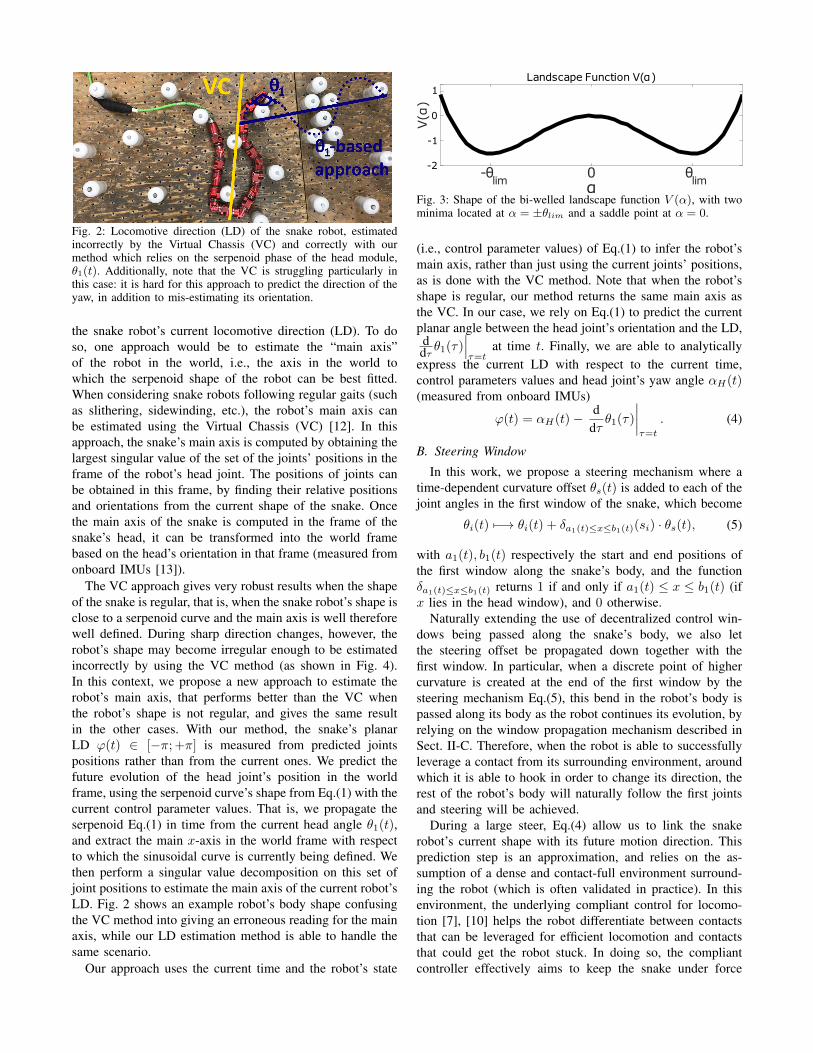
Fig. 2: Locomotive direction (LD) of the snake robot, estimatedincorrectly by the Virtual Chassis (VC) and correctly with ourmethod which relies on the serpenoid phase of the head module,θ1(t). Additionally, note that the VC is struggling particularly inthis case: it is hard for this approach to predict the direction of theyaw, in addition to mis-estimating its orientation.
the snake robot’s current locomotive direction (LD). To doso, one approach would be to estimate the “main axis”of the robot in the world, i.e., the axis in the world towhich the serpenoid shape of the robot can be best fitted.When considering snake robots following regular gaits (suchas slithering, sidewinding, etc.), the robot’s main axis canbe estimated using the Virtual Chassis (VC) [12]. In thisapproach, the snake’s main axis is computed by obtaining thelargest singular value of the set of the joints’ positions in theframe of the robot’s head joint. The positions of joints canbe obtained in this frame, by finding their relative positionsand orientations from the current shape of the snake. Oncethe main axis of the snake is computed in the frame of thesnake’s head, it can be transformed into the world framebased on the head’s orientation in that frame (measured fromonboard IMUs [13]).
The VC approach gives very robust results when the shapeof the snake is regular, that is, when the snake robot’s shape isclose to a serpenoid curve and the main axis is well thereforewell defined. During sharp direction changes, however, therobot’s shape may become irregular enough to be estimatedincorrectly by using the VC method (as shown in Fig. 4).In this context, we propose a new approach to estimate therobot’s main axis, that performs better than the VC whenthe robot’s shape is not regular, and gives the same resultin the other cases. With our method, the snake’s planarLD ϕ(t) ∈ [−π; +π] is measured from predicted jointspositions rather than from the current ones. We predict thefuture evolution of the head joint’s position in the worldframe, using the serpenoid curve’s shape from Eq.(1) with thecurrent control parameter values. That is, we propagate theserpenoid Eq.(1) in time from the current head angle θ1(t),and extract the main x-axis in the world frame with respectto which the sinusoidal curve is currently being defined. Wethen perform a singular value decomposition on this set ofjoint positions to estimate the main axis of the current robot’sLD. Fig. 2 shows an example robot’s body shape confusingthe VC method into giving an erroneous reading for the mainaxis, while our LD estimation method is able to handle thesame scenario.
Our approach uses the current time and the robot’s state
α-θ
lim0 θ
lim
V(α
)
-1012Landscape Function V(α)
-1
-2
0
1
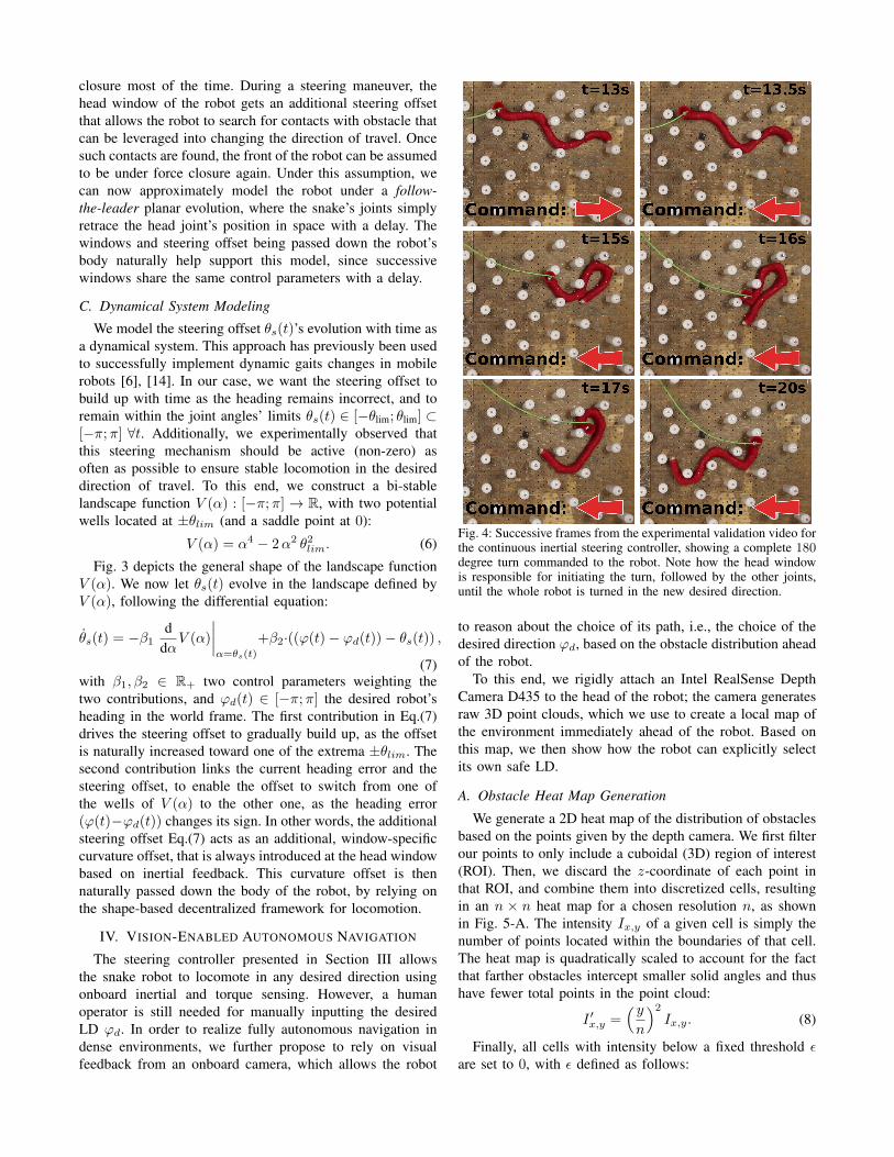
Fig. 3: Shape of the bi-welled landscape function V (α), with twominima located at α = ±θlim and a saddle point at α = 0.
(i.e., control parameter values) of Eq.(1) to infer the robot’smain axis, rather than just using the current joints’ positions,as is done with the VC method. Note that when the robot’sshape is regular, our method returns the same main axis asthe VC. In our case, we rely on Eq.(1) to predict the currentplanar angle between the head joint’s orientation and the LD,ddτ θ1(τ)
∣∣∣τ=t
at time t. Finally, we are able to analyticallyexpress the current LD with respect to the current time,control parameters values and head joint’s yaw angle αH(t)(measured from onboard IMUs)
ϕ(t) = αH(t)− ddτθ1(τ)
∣∣∣∣τ=t
. (4)
B. Steering Window
In this work, we propose a steering mechanism where atime-dependent curvature offset θs(t) is added to each of thejoint angles in the first window of the snake, which become
θi(t) 7−→ θi(t) + δa1(t)≤x≤b1(t)(si) · θs(t), (5)
with a1(t), b1(t) respectively the start and end positions ofthe first window along the snake’s body, and the functionδa1(t)≤x≤b1(t) returns 1 if and only if a1(t) ≤ x ≤ b1(t) (ifx lies in the head window), and 0 otherwise.
Naturally extending the use of decentralized control win-dows being passed along the snake’s body, we also letthe steering offset be propagated down together with thefirst window. In particular, when a discrete point of highercurvature is created at the end of the first window by thesteering mechanism Eq.(5), this bend in the robot’s body ispassed along its body as the robot continues its evolution, byrelying on the window propagation mechanism described inSect. II-C. Therefore, when the robot is able to successfullyleverage a contact from its surrounding environment, aroundwhich it is able to hook in order to change its direction, therest of the robot’s body will naturally follow the first jointsand steering will be achieved.
During a large steer, Eq.(4) allow us to link the snakerobot’s current shape with its future motion direction. Thisprediction step is an approximation, and relies on the as-sumption of a dense and contact-full environment surround-ing the robot (which is often validated in practice). In thisenvironment, the underlying compliant control for locomo-tion [7], [10] helps the robot differentiate between contactsthat can be leveraged for efficient locomotion and contactsthat could get the robot stuck. In doing so, the compliantcontroller effectively aims to keep the snake under force
closure most of the time. During a steering maneuver, thehead window of the robot gets an additional steering offsetthat allows the robot to search for contacts with obstacle thatcan be leveraged into changing the direction of travel. Oncesuch contacts are found, the front of the robot can be assumedto be under force closure again. Under this assumption, wecan now approximately model the robot under a follow-the-leader planar evolution, where the snake’s joints simplyretrace the head joint’s position in space with a delay. Thewindows and steering offset being passed down the robot’sbody naturally help support this model, since successivewindows share the same control parameters with a delay.
C. Dynamical System Modeling
We model the steering offset θs(t)’s evolution with time asa dynamical system. This approach has previously been usedto successfully implement dynamic gaits changes in mobilerobots [6], [14]. In our case, we want the steering offset tobuild up with time as the heading remains incorrect, and toremain within the joint angles’ limits θs(t) ∈ [−θlim; θlim] ⊂[−π;π] ∀t. Additionally, we experimentally observed thatthis steering mechanism should be active (non-zero) asoften as possible to ensure stable locomotion in the desireddirection of travel. To this end, we construct a bi-stablelandscape function V (α) : [−π;π] → R, with two potentialwells located at ±θlim (and a saddle point at 0):
V (α) = α4 − 2α2 θ2lim. (6)
Fig. 3 depicts the general shape of the landscape functionV (α). We now let θs(t) evolve in the landscape defined byV (α), following the differential equation:
θs(t) = −β1d
dαV (α)
∣∣∣∣α=θs(t)
+β2·((ϕ(t)− ϕd(t))− θs(t)) ,
(7)with β1, β2 ∈ R+ two control parameters weighting thetwo contributions, and ϕd(t) ∈ [−π;π] the desired robot’sheading in the world frame. The first contribution in Eq.(7)drives the steering offset to gradually build up, as the offsetis naturally increased toward one of the extrema ±θlim. Thesecond contribution links the current heading error and thesteering offset, to enable the offset to switch from one ofthe wells of V (α) to the other one, as the heading error(ϕ(t)−ϕd(t)) changes its sign. In other words, the additionalsteering offset Eq.(7) acts as an additional, window-specificcurvature offset, that is always introduced at the head windowbased on inertial feedback. This curvature offset is thennaturally passed down the body of the robot, by relying onthe shape-based decentralized framework for locomotion.
IV. VISION-ENABLED AUTONOMOUS NAVIGATION
The steering controller presented in Section III allowsthe snake robot to locomote in any desired direction usingonboard inertial and torque sensing. However, a humanoperator is still needed for manually inputting the desiredLD ϕd. In order to realize fully autonomous navigation indense environments, we further propose to rely on visualfeedback from an onboard camera, which allows the robot
Fig. 4: Successive frames from the experimental validation video forthe continuous inertial steering controller, showing a complete 180degree turn commanded to the robot. Note how the head windowis responsible for initiating the turn, followed by the other joints,until the whole robot is turned in the new desired direction.
to reason about the choice of its path, i.e., the choice of thedesired direction ϕd, based on the obstacle distribution aheadof the robot.
To this end, we rigidly attach an Intel RealSense DepthCamera D435 to the head of the robot; the camera generatesraw 3D point clouds, which we use to create a local map ofthe environment immediately ahead of the robot. Based onthis map, we then show how the robot can explicitly selectits own safe LD.
A. Obstacle Heat Map Generation
We generate a 2D heat map of the distribution of obstaclesbased on the points given by the depth camera. We first filterour points to only include a cuboidal (3D) region of interest(ROI). Then, we discard the z-coordinate of each point inthat ROI, and combine them into discretized cells, resultingin an n × n heat map for a chosen resolution n, as shownin Fig. 5-A. The intensity Ix,y of a given cell is simply thenumber of points located within the boundaries of that cell.The heat map is quadratically scaled to account for the factthat farther obstacles intercept smaller solid angles and thushave fewer total points in the point cloud:
I ′x,y =( yn
)2Ix,y. (8)
Finally, all cells with intensity below a fixed threshold εare set to 0, with ε defined as follows:
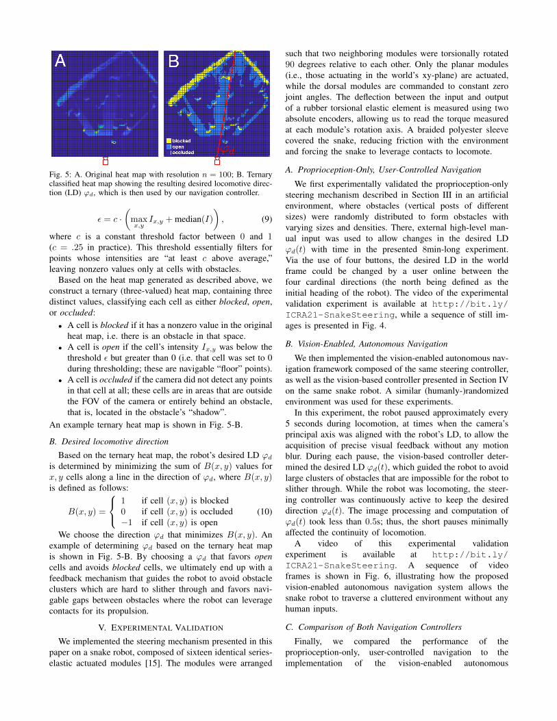
Fig. 5: A. Original heat map with resolution n = 100; B. Ternaryclassified heat map showing the resulting desired locomotive direc-tion (LD) ϕd, which is then used by our navigation controller.
ε = c ·(
maxx,y
Ix,y + median(I)
), (9)
where c is a constant threshold factor between 0 and 1(c = .25 in practice). This threshold essentially filters forpoints whose intensities are “at least c above average,”leaving nonzero values only at cells with obstacles.
Based on the heat map generated as described above, weconstruct a ternary (three-valued) heat map, containing threedistinct values, classifying each cell as either blocked, open,or occluded:• A cell is blocked if it has a nonzero value in the original
heat map, i.e. there is an obstacle in that space.• A cell is open if the cell’s intensity Ix,y was below the
threshold ε but greater than 0 (i.e. that cell was set to 0during thresholding; these are navigable “floor” points).
• A cell is occluded if the camera did not detect any pointsin that cell at all; these cells are in areas that are outsidethe FOV of the camera or entirely behind an obstacle,that is, located in the obstacle’s “shadow”.
An example ternary heat map is shown in Fig. 5-B.
B. Desired locomotive direction
Based on the ternary heat map, the robot’s desired LD ϕdis determined by minimizing the sum of B(x, y) values forx, y cells along a line in the direction of ϕd, where B(x, y)is defined as follows:
B(x, y) =
1 if cell (x, y) is blocked0 if cell (x, y) is occluded−1 if cell (x, y) is open
(10)
We choose the direction ϕd that minimizes B(x, y). Anexample of determining ϕd based on the ternary heat mapis shown in Fig. 5-B. By choosing a ϕd that favors opencells and avoids blocked cells, we ultimately end up with afeedback mechanism that guides the robot to avoid obstacleclusters which are hard to slither through and favors navi-gable gaps between obstacles where the robot can leveragecontacts for its propulsion.
V. EXPERIMENTAL VALIDATION
We implemented the steering mechanism presented in thispaper on a snake robot, composed of sixteen identical series-elastic actuated modules [15]. The modules were arranged
such that two neighboring modules were torsionally rotated90 degrees relative to each other. Only the planar modules(i.e., those actuating in the world’s xy-plane) are actuated,while the dorsal modules are commanded to constant zerojoint angles. The deflection between the input and outputof a rubber torsional elastic element is measured using twoabsolute encoders, allowing us to read the torque measuredat each module’s rotation axis. A braided polyester sleevecovered the snake, reducing friction with the environmentand forcing the snake to leverage contacts to locomote.
A. Proprioception-Only, User-Controlled Navigation
We first experimentally validated the proprioception-onlysteering mechanism described in Section III in an artificialenvironment, where obstacles (vertical posts of differentsizes) were randomly distributed to form obstacles withvarying sizes and densities. There, external high-level man-ual input was used to allow changes in the desired LDϕd(t) with time in the presented 8min-long experiment.Via the use of four buttons, the desired LD in the worldframe could be changed by a user online between thefour cardinal directions (the north being defined as theinitial heading of the robot). The video of the experimentalvalidation experiment is available at http://bit.ly/ICRA21-SnakeSteering, while a sequence of still im-ages is presented in Fig. 4.
B. Vision-Enabled, Autonomous Navigation
We then implemented the vision-enabled autonomous nav-igation framework composed of the same steering controller,as well as the vision-based controller presented in Section IVon the same snake robot. A similar (humanly-)randomizedenvironment was used for these experiments.
In this experiment, the robot paused approximately every5 seconds during locomotion, at times when the camera’sprincipal axis was aligned with the robot’s LD, to allow theacquisition of precise visual feedback without any motionblur. During each pause, the vision-based controller deter-mined the desired LD ϕd(t), which guided the robot to avoidlarge clusters of obstacles that are impossible for the robot toslither through. While the robot was locomoting, the steer-ing controller was continuously active to keep the desireddirection ϕd(t). The image processing and computation ofϕd(t) took less than 0.5s; thus, the short pauses minimallyaffected the continuity of locomotion.
A video of this experimental validationexperiment is available at http://bit.ly/ICRA21-SnakeSteering. A sequence of videoframes is shown in Fig. 6, illustrating how the proposedvision-enabled autonomous navigation system allows thesnake robot to traverse a cluttered environment without anyhuman inputs.
C. Comparison of Both Navigation Controllers
Finally, we compared the performance of theproprioception-only, user-controlled navigation to theimplementation of the vision-enabled autonomous

Fig. 6: Snapshots from the experimental validation video for the proposed vision-enabled autonomous navigation framework. The robot iscapable of autonomously traversing the densely-cluttered environment. In each frame, the obstacle heat map generated by the vision-basedcontroller is displayed in the shaded blue area; the robot’s desired propagating direction determined by the vision system is shown by thesolid red line.
navigation in locally traversing an unstructuredenvironment. A video comparison can be found athttp://bit.ly/ICRA21-SnakeSteering.
As expected, navigation with vision feedforward is asignificant improvement in environments with visually dis-tinguishable, non-navigable clusters of obstacles, since thefeedforward system can pre-emptively identify potential“problem areas” and steer ahead of time to avoid them.Conversely, proprioception-only navigation can only attemptto negotiate the obstacles once it is aware of their existence,i.e., after making contact with them, at which time the robotcould already be stuck against a row of obstacles with noclear means to get itself unstuck short of tracing back its path.
VI. DISCUSSION
In practice, the full, vision-enabled navigation frameworkdetailed in this work was very accurate in choosing anappropriate direction ϕd(t), in an environment with a rangeof obstacle shapes and sizes (small pegs, large pegs, pegboardframe, and wall, as well as clusters of the above). Ourframework also appeared robust to the presence of large non-navigable empty spaces (such as off the edge of the elevatedpegboard), even if those areas had no obstacles.
However, our current use of visual feedback still exhibitsseveral physical limitations. For instance, the camera has aminimum viable range of around 11cm, which prevents itfrom detecting obstacles that the robot is directly adjacent to.Similarly, at ranges above 1.5m, the 3D point cloud generatedby the camera becomes relatively unstable and noisy, limitingour ability to detect further-off “dead ends” if their endis outside of the field of view of the camera. Finally, wenote that the camera must be relatively steady in order togenerate usable visual feedback, thus necessitating the 0.5spauses described previously, which might limit the use ofour method in time-critical scenarios.
Importantly, since the system is inherently an local plan-ner, it does no high-level mapping or localization. In contrastto “proprioception-only” global navigation, which choosesa target direction and preserves a constant LD to thatdirection, our vision-based local navigation system currentlyonly selects a locally high-quality LD, without consideringprior information nor global targets.
This means that the robot could be caught in a cycleof short-term optima, rather than progressing towards some
global target. For instance, the vision feedforward systemmay cause the robot to get caught in a loop of successiveopen areas that cause it to periodically re-visit the samelocations, while making no progress in the long term - ascenario that the proprioception-only controller would avoiddue to its global LD. Future work includes integration oflimited vision-based localization, which can be used tocombine these two approaches (local and global planning),which due to scope and space constraints were not treatedin this work.
VII. CONCLUSION AND PERSPECTIVES
In this work, we developed a closed-loop autonomousnavigation framework for snake robot locomotion in unstruc-tured dense environments, which we experimentally vali-dated on hardware in a number of experiments. Our frame-work is built upon a novel, dynamical system based contin-uous steering controller, which builds upon the state-of-the-art shape-based decentralized compliant control framework.While this controller allows the robot to continuously steerand keep a given direction of travel in the world, we furtherproposed to allow the robot to explicit select this directionbased on visual feedback from an onboard camera, e.g., tosteer away and avoid challenging regions that could not benegotiated through feedback control only.
The continuous steering controller and the vision feed-forward system can be seen as modular pieces that wewould like to further investigate the coordination of themin the future work. That is, our steering controller enablesthe robot to navigate in a given global direction in theworld, while visual feedback can allow local, predictive pathplanning. However, integrating these long- and short-termplanning methods is nontrivial, since their individual goalsmight not agree, especially around complex scenarios, e.g.,situations where multiple routes are possible, or situationswhere the only safe course of action does not agree withthe desired global direction of travel. Future works willlook to filtering/consensus methods to dynamically combinethese two modular controllers, as well as to explicit SLAMmethods to allow the robot a higher-level of reasoning aboutglobal path planning and already visited areas, e.g., forautonomous exploration tasks.

REFERENCES
[1] F. Sanfilippo, J. Azpiazu, G. Marafioti, A. A. Transeth, Ø. Stavdahl,and P. Liljeback, “Perception-driven obstacle-aided locomotion forsnake robots: the state of the art, challenges and possibilities,” AppliedSciences, vol. 7, no. 4, p. 336, 2017.
[2] J. Whitman, N. Zevallos, M. Travers, and H. Choset, “Snake roboturban search after the 2017 mexico city earthquake,” in Proceedingsof the IEEE International Symposium on Safety, Security, and RescueRobotics, 2018.
[3] P. E. Schiebel, J. M. Rieser, A. M. Hubbard, L. Chen, and D. I.Goldman, “Collisional diffraction emerges from simple control oflimbless locomotion,” in Conference on Biomimetic and BiohybridSystems. Springer, 2017, pp. 611–618.
[4] M. Travers, J. Whitman, P. Schiebel, D. Goldman, and H. Choset,“Shape-based compliance in locomotion,” in Proceedings of Robotics:Science and Systems, AnnArbor, Michigan, June 2016.
[5] T. Wang, J. Whitman, M. Travers, and H. Choset, “Directionalcompliance in obstacle-aided navigation for snake robots,” in 2020American Control Conference (ACC), 2020, pp. 2458–2463.
[6] F. Ruscelli, G. Sartoretti, J. Nan, Z. Feng, M. Travers, andH. Choset, “Proprioceptive-inertial autonomous locomotion for artic-ulated robots,” in ICRA 2018 - IEEE International Conference onRobotics and Automation, 2018, pp. 3436–3441.
[7] J. Whitman, F. Ruscelli, M. Travers, and H. Choset, “Shape-basedcompliant control with variable coordination centralization on a snakerobot,” in CDC 2016, December 2016.
[8] S. Hirose, Biologically Inspired Robots: Serpentile Locomotors andManipulators. Oxford University Press, 1993.
[9] P. Liljeback, K. Pettersen, Ø. Stavdahl, and J. Gravdahl, Snake Robots:Modelling, Mechatronics, and Control, 01 2013.
[10] M. Travers, J. Whitman, and H. Choset, “Shape-based coordination inlocomotion control,” The International Journal of Robotics Research,p. 0278364918761569, 2018.
[11] M. Tesch, K. Lipkin, I. Brown, R. Hatton, A. Peck, J. Rembisz,and H. Choset, “Parameterized and scripted gaits for modular snakerobots,” Advanced Robotics, vol. 23, no. 9, pp. 1131–1158, 2009.
[12] D. Rollinson and H. Choset, “Virtual chassis for snake robots,” in IEEEInternational Conference on Intelligent Robots and Systems, 2011, pp.221–226.
[13] D. Rollinson, H. Choset, and S. Tully, “Robust state estimation withredundant proprioceptive sensors,” in ASME 2013 Dynamic Systemsand Control Conference, October 2013.
[14] M. Travers, A. Ansari, and H. Choset, “A dynamical systems approachto obstacle navigation for a series-elastic hexapod robot,” in 2016 IEEEConference on Decision and Control, December 2016.
[15] D. Rollinson, Y. Bilgen, B. Brown, F. Enner, S. Ford, C. Layton,J. Rembisz, M. Schwerin, A. Willig, P. Velagapudi, and H. Choset,“Design and architecture of a series elastic snake robot,” in IEEEInternational Conference on Intelligent Robots and Systems, 2014, pp.4630–4636.